В. Белотелов
«Квант» №1, 2010
В последнее время идея создания оптических компьютеров приобретает все большую популярность. Она подкрепляется, с одной стороны, неиссякающим стремлением к все большим скоростям вычислений, а с другой стороны — удивительными возможностями современных технологий. Для того чтобы обрабатывать и передавать информацию с помощью света, т. е. с помощью фотонов, надо научиться эффективно управлять ими. Хотя электрического заряда у фотонов нет, но наличие поляризации — ориентации их электромагнитного поля — дает определенную надежду на успех.
Прежде всего перенесемся в конец XIX века, в лабораторию великого английского физика Майкла Фарадея — ведь именно оттуда берет исток наша история.
«Намагнитить луч света и осветить магнитную силовую линию»
Разнообразные физические явления, связанные с магнитными и оптическими свойствами среды, в течение многих столетий изучались независимо. Свет сопровождает человечество с момента его зарождения, а магнетизм известен с древних времен. Однако только в 1845 году М. Фарадей впервые провел эксперименты, доказавшие связь между этими явлениями. Отчасти это связано с тем, что в обычных условиях магнитооптические эффекты весьма малы и для их открытия требовалась физическая интуиция гения. Удивительно, что это произошло в то время, когда не было ясного понимания ни природы магнитных свойств, ни природы оптических явлений и когда еще не были сформулированы уравнения Максвелла.
«Я уже давно придерживался мнения, что различные формы и силы материи настолько близки и родственны, что могут превращаться друг в друга. Это твердое убеждение побудило меня произвести много изысканий с целью открыть связь между светом и электричеством. Однако результаты оказались отрицательными…» — так сам Фарадей комментирует свои опыты.
«Эти безуспешные изыскания не могли поколебать моего твердого убеждения, основанного на научных соображениях. Поэтому я недавно возобновил исследование на очень тонких и строгих началах, и в конце концов мне удалось намагнитить и наэлектризовать луч света и осветить магнитную силовую линию.»
В словах «намагнитить луч света» подразумевается вызываемое магнитным полем вращение плоскости поляризации света — магнитооптический эффект Фарадея. Кроме того, обращают на себя внимание и слова «осветить магнитную силовую линию», намекающие на возможное обратное влияние света на магнетизм. В опытах Фарадея такого явления обнаружено не было, но эти слова указывают на то, что великий физик фактически предсказал и его. Влияние света на магнитные свойства вещества было теоретически доказано гораздо позже. В 1960 году советский физик Л. П. Питаевский показал, что свет, обладающий круговой поляризацией, способен намагнитить среду, которую он освещает. Эффект получил название обратного эффекта Фарадея.
Хотя обратный эффект Фарадея тоже имеет большую практическую значимость, в этой статье речь пойдет только о прямом магнитооптическом эффекте, ведь наша цель — управлять светом, используя магнитное поле.
Спин и поляризация фотонов
Напомним, что можно говорить о естественном, т. е. неполяризованном, свете, а также можно выделить три основные состояния поляризации: плоская, круговая и эллиптическая поляризации. В общем случае поляризованный свет обладает эллиптической поляризацией, т. е. траектория проекции конца вектора напряженности электрического поля волны на плоскость, перпендикулярную направлению ее распространения, является эллипсом. Наибольший практический интерес представляют два крайних случая эллиптической поляризации: линейная поляризация, когда эллипс вырождается в отрезок, и круговая поляризация, при которой эллипс превращается в окружность.
С квантово-механической точки зрения, понятие поляризации света связано с наличием у фотона спина. Фотоны, как частицы с нулевой массой покоя, могут находиться в двух состояниях со значениями момента импульса ±ћ (ћ — постоянная Планка), направленного вдоль импульса фотона. Такие фотоны обладают круговой поляризацией: левой, когда квантовое число m = +1, или правой, когда m = –1. Эллиптически поляризованные фотоны находятся в состоянии, которое складывается из состояний с m = ±1; при линейной поляризации суперпозиция этих состояний такова, что средняя проекция момента на направление импульса равна нулю.
Эффект Фарадея
У свободного фотона состояния с m = +1 и m = –1 имеют одинаковые энергии (частоты). В квантовой механике такую ситуацию называют вырождением. Снять вырождение можно при помощи внешнего магнитного поля, направленного вдоль волнового вектора (предполагается, что фотон распространяется в среде с показателем преломления n). В магнитном поле компоненты с m = ±1 будут распространяться с разными фазовыми скоростями:
Здесь c — скорость света, n — показатель преломления среды, a Q — специальный магнитооптический параметр. В немагнитных средах параметр Q пропорционален магнитному полю и в не очень больших полях (магнитная индукция не превышает 200–300 мТл) имеет типичное значение порядка 10–6–10–4. В ферромагнитных материалах этот параметр отличен от нуля даже в отсутствие поля и достигает величин 10–3–10–1. Он определяется внутренним магнитным полем, которое создается атомами и ионами кристаллической решетки магнетика.
Но с фазовой скоростью непосредственно связан показатель преломления среды:
В результате получается, что в магнитной среде волны, поляризованные по часовой стрелке и против нее, преломляются по-разному — возникает явление циркулярного двойного лучепреломления, или гиротропии среды. Явление гиротропии связано с эффектом Зеемана, т. е. с расщеплением линий поглощения света в магнитном поле. Под действием силы Лоренца резонансные частоты вращения электронов по левому и правому кругу смещаются в различные стороны относительно первоначального значения собственной частоты. Это, в свою очередь, и приводит к различию показателей преломления для волн, поляризованных по правому и по левому кругу. Экспериментально при этом наблюдается эффект Фарадея, проявляющийся в том, что плоско поляризованный свет, распространяясь вдоль направления намагниченности, испытывает поворот плоскости поляризации на некоторый угол.
Чтобы объяснить это явление, представим плоско поляризованную волну как сумму левой и правой циркулярно поляризованных волн. Если обе волны имеют одинаковые фазовые скорости, то, распространяясь вместе, они складываются и дают волну, которая плоско поляризована вдоль фиксированного направления. Но если их фазовые скорости различаются, то при распространении одна волна будет обгонять другую и плоскость поляризации суммарной волны будет постепенно поворачиваться — наблюдается эффект Фарадея (рис. 1). Угол поворота плоскости поляризации излучения на выходе из ферромагнетика пропорционален магнитооптическому параметру Q и длине пути волны в намагниченной среде.
Эффект Фарадея широко используют для наблюдения магнитной структуры в прозрачных пленках, в которых намагниченность перпендикулярна или почти перпендикулярна поверхности пленки. Этот эффект — один из наиболее действенных механизмов управления поляризацией света. Он широко применяется в лазерной технике, информатике и других областях. Можно сказать, что эффект Фарадея является основой магнитооптики — раздела оптики, в котором изучают влияние магнитного поля на оптические свойства вещества.
Наряду с эффектом Фарадея существует множество других магнитооптических явлений, среди которых стоит еще упомянуть эффект Керра. Он состоит в изменении характеристик световой волны при отражении от магнитной среды. При этом, в зависимости от геометрии падения света, будет меняться либо его поляризация, либо интенсивность, либо и то и другое вместе.
Два пути к совершенству
Магнетизм воздействует на свет, но это действие обычно весьма мало. А как же тогда магнитное поле сможет управлять светом? Ответ вроде бы очевиден: магнитооптические эффекты необходимо каким-то образом увеличить.
В 70–80-е годы прошлого века, когда экспериментальная магнитооптика переживала бурное развитие, ученые шли по пути подбора оптимального химического состава. Одним из наиболее распространенных магнитооптических материалов является ферромагнитный диэлектрик редкоземельный феррит-гранат с ионами висмута. Его химическая формула RхВi3–хFе5O12. В ней R обозначает один или несколько редкоземельных ионов, а х задает относительную концентрацию редкоземельных ионов и висмута. На основании многочисленных экспериментов были выявлены составы ферритов-гранатов, обеспечивающие в видимом и ближнем инфракрасном свете большие магнитооптические эффекты и малое оптическое поглощение. К примеру, намагниченная пленка феррита-граната состава Dy0,5Вi2,5Fе5O12 толщиной 10 мкм способна повернуть плоскость поляризации красного света на угол около 20°, что вполне подходит для возможных применений. Однако в поиске подходящего состава вещества в конце концов наступило насыщение, и прогресс затормозился.
К счастью, существует и другой альтернативный подход, связанный с так называемыми оптическими наноструктурированными материалами — средами, оптические свойства которых (например, показатель преломления) изменяются в пространстве на масштабе менее нескольких сотен нанометров. Ярким примером таких материалов являются фотонные кристаллы.
Фотонные кристаллы — это периодические диэлектрические или металло-диэлектрические материалы, которые воздействуют на распространяющиеся по ним световые волны таким же образом, как и периодический потенциал в кристаллах влияет на движение электронов, приводя к образованию разрешенных и запрещенных энергетических зон. Поскольку в основе идеи фотонного кристалла лежат явления дифракции и интерференции, то период структуры фотонного кристалла должен быть порядка длины волны электромагнитного излучения в веществе, т. е. около 300 нм для работы в диапазоне видимого света. Примером одномерных фотонных кристаллов служит многослойная структура из чередующихся слоев прозрачных веществ с двумя различными показателями преломления (рис. 2, а). Система параллельных отверстий в диэлектрическом слое формирует двумерный фотонный кристалл (рис. 2, б), а плотно упакованные наносферы кварца представляют собой трехмерный фотонный кристалл (рис. 2, в).
Чем же замечательны наноструктурированные материалы и, в частности, фотонные кристаллы? Тем, что их оптические свойства — направление, интенсивность и поляризация отраженного и прошедшего света — определяются не только и даже не столько показателями преломления веществ, из которых они сделаны, а их структурой. Специально подобранная структура вещества приводит к явлениям интерференции и дифракции, существенно меняющим условия прохождения света через материал. Так, в фотонных кристаллах возникают запрещенные зоны — области частот света, при которых свет не может проникнуть внутрь фотонного кристалла и полностью отражается от него. Появление наноструктурированных материалов фактически открывает новое направление в создании оптических сред. Необходимые оптические свойства материала достигают теперь не путем подбора оптимального химического состава (как это было в старом подходе), а путем создания геометрической или фазовой структуры с характерным размером, не превышающим нескольких сотен нанометров. Поскольку наноструктурированные материалы создают искусственно, их часто называют метама-териалами.
Намагниченные фотонные кристаллы
Если наноструктурированный материал содержит магнитные вещества, то можно ожидать, что в нем будут наблюдаться магнитооптические эффекты, аналогичные тем, что возникают в обычных однородных средах, но, возможно, несколько измененные. Идея использовать для управления света в фотонном кристалле магнитные вещества впервые была предложена в конце 90-х годов минувшего столетия японскими учеными. Они рассмотрели эффект Фарадея в одномерных фотонных кристаллах, представляющих собой многослойные пленки из хаотично чередующихся слоев висмут-замещенного иттриевого феррита-граната и кварца. Для определенных частот излучения при оптимально подобранных параметрах структуры было обнаружено увеличение эффекта Фарадея более чем в 300 раз по сравнению с аналогичной однородной средой.
На примере одномерного случая можно выделить несколько разновидностей магнитных фотонных кристаллов. Прежде всего, это стандартные системы, состоящие из чередующихся четвертьволновых (толщина равна одной четвертой длины волны света в веществе) магнитных (например, церий-замещенный иттриевый феррит-гранат) и немагнитных (например, гадолиний-галлиевый гранат) слоев. Такие фотонные кристаллы обладают запрещенной зоной с центром на проектировочной длине волны, т. е. не пропускают свет с длиной волны в некоторой области вокруг данной. Под проектировочной длиной волны подразумевают длину волны света вне кристалла, при которой в каждом из его слоев укладывается одна четвертая длины волны. На рисунке 3, а и б показаны зависимости коэффициента пропускания и угла Фарадея для одномерного фотонного кристалла, настроенного на ближний инфракрасный диапазон (проектировочная длина волны 1,55 мкм). Кристалл состоит из 30 пар магнитного и немагнитного слоев. Усиление эффекта Фарадея возникает на границе запрещенной зоны, т. е. в районе длин волн 1,49 мкм и 1,61 мкм. Оказывается, именно на этих длинах волн резко возрастает групповая скорость света. Это приводит к тому, что возрастает эффективное время взаимодействия волны с намагниченностью материала, а значит, и увеличивается эффект Фарадея.
Важной особенностью резонансов на граничных частотах является то, что максимумы прохождения и фарадеевского вращения практически совпадают. Это позволяет использовать фотонные кристаллы в качестве миниатюрных элементов, вращающих плоскость поляризации на большие углы. Оптимальный подбор магнитных материалов, их геометрических размеров и расположения позволит создать новое поколение оптических устройств, управляемых магнитными полями. При этом нужно иметь в виду не только инфракрасный, но и видимый диапазон света.
В одномерных магнитных фотонных кристаллах можно создать структурные дефекты — несколько раз инвертировать порядок следования слоев и тем самым получить один или несколько слоев с удвоенной толщиной. Наличие таких дефектов приводит к появлению в фотонной запрещенной зоне узких резонансных уровней, на частотах которых прохождение света близко к стопроцентному (рис. 3, в). Вместе с тем, групповая скорость излучения на этих резонансах вновь оказывается очень малой, и эффект Фарадея при этом резко возрастает (рис. 3, г). В результате удается получить пик пропускания нужной ширины и большой угол Фарадея. К примеру, на длинах волн ближнего инфракрасного диапазона с помощью таких фотонных материалов удается получить угол поворота поляризации света на 45° на расстоянии всего 1,5 мкм, в то время как для той же однородной среды указанный угол поворота достигается на расстоянии, в 150 раз большем.
Однако усиление эффекта Фарадея в фотонных кристаллах впервые было экспериментально продемонстрировано японскими учеными на структуре другого типа. Она представляет собой магнитный микрорезонатор — внутрь немагнитного резонатора помещают слой магнитного материала. Хотя изготовить такую систему проще, чем предыдущие разновидности магнитных фотонных кристаллов, она демонстрирует все же менее впечатляющие результаты.
В последние несколько лет начали исследовать и многомерные магнитные фотонные кристаллы. Работа с такими системами существенно расширяет круг наблюдаемых эффектов, а также приводит к новым интересным применениям. Экспериментальные и теоретические исследования двумерных и трехмерных магнитных фотонных кристаллов активно ведутся в нашей стране (в МГУ им. М. В. Ломоносова, в Физико-техническом институте им. А. Ф. Иоффе), а также в Японии, Австралии, Швеции и ряде других стран. В большинстве случаев экспериментальной реализации эти структуры представляют собой коллоидные растворы упорядоченных частиц сферической или цилиндрической формы. Например, созданы двумерные коллоидные фотонные кристаллы, состоящие из стеклянных волокон, покрытых никелем. Резкое увеличение эффекта Фарадея было зафиксировано в трехмерных коллоидных кристаллах из кварцевых сфер, промежутки между которыми заполнены магнитной жидкостью насыщенного раствора нитрата диспрозия в глицерине.
До сих пор мы говорили только про усиление в фотонных кристаллах эффекта Фарадея. Однако необходимо отметить, что и другие магнитооптические эффекты могут быть существенно усилены благодаря специально подобранной оптической структуре среды. Следовательно, имея в руках образец такого фотонного кристалла толщиной всего несколько микрометров, можно действительно эффективно управлять светом, в первую очередь меняя его поляризацию.
Магнитооптика на службе
Настало время поговорить о том, где может использоваться магнитооптика. Начнем с передачи информации. Поскольку в оптических компьютерах биты информации передаются световыми волнами, то для их реализации нужно научиться менять или, говоря иначе, модулировать с высокой частотой интенсивность света. Вот здесь и должен пригодиться усиленный эффект Фарадея.
Действительно, магнитооптический модулятор можно организовать так: расположить магнитный фотонный кристалл с большим магнитооптическим параметром между двумя поляризаторами, скрещенными под углом 45°, и менять его намагниченность внешним магнитным полем в таких пределах, чтобы угол поворота плоскости поляризации также составил 45°. Тогда при максимальной намагниченности, например, вдоль оси OX поляризация света на выходе из слоя окажется параллельной направлению пропускания анализатора, и почти вся световая энергия пройдет через модулятор. В то же время при максимальной намагниченности слоя против оси OX плоскость поляризации света повернется в противоположную сторону и будет перпендикулярна оси анализатора — свет полностью поглотится. При промежуточных значениях намагниченности угол Фарадея будет меньше 45°, и только часть излучения выйдет наружу. Получается, что, изменяя магнитное поле, удается влиять на интенсивность прошедшего света. Очень важным фактором при этом является скорость переключения. Магнитные материалы позволяют достигать частот переключения вплоть до десятков гигагерц, что соответствует времени переключения порядка долей наносекунды. (Для сравнения стоит сказать, что переключение в жидкокристаллических веществах происходит за микросекунды.)
Эффективно и быстро изменять интенсивность светового потока крайне важно не только в фотонных чипах оптических компьютеров будущего, но и в других оптических устройствах. Например, на базе магнитного фотонного кристалла можно создать миниатюрные ячейки, пропускающие свет заданного цвета — красного, синего или зеленого. Такие ячейки можно объединить в единую систему и из получившихся пикселей создать монитор или видеопроектор (рис. 4). Адресно прикладывая внешнее магнитное поле к цветным пикселям, можно управлять яркостью того или иного цвета и придавать пикселю требуемый оттенок, формируя яркое, насыщенное цветное изображение.
Сейчас все большую популярность приобретает так называемая электронная бумага — гибкий монитор, позволяющий читать электронные книги и газеты. В настоящее время уже появились такие устройства, обеспечивающие черно-белое изображение. Оказывается, магнитное поле здесь тоже может оказаться полезным. Как следует из совсем свежей работы корейских ученых, магнитные фотонные кристаллы, состоящие из магнитных наночастиц в полимерных микросферах, могут позволить сделать следующий шаг — создать цветную электронную бумагу. Принцип действия элемента такого фотонного кристалла схематически изображен на рисунке 5. Микросфера с магнитным фотонным кристаллом внутри может свободно вращаться, будучи взвешена в машинном масле. Если излучение падает в направлении магнитной цепочки (или под острым углом меньше 15°), то цвет отраженного излучения определяется в основном расстоянием между наночастицами. Если же под действием магнитного поля частица повернется так, что цепочки магнитных частиц ориентируются перпендикулярно лучу света, то микросфера станет бесцветной. Таким образом, в данном случае магнитное поле помогает управлять цветом не непосредственно через магнитооптические эффекты, а опосредованно — ориентируя фотонный кристалл нужным образом. В то же время и про эффект Фарадея тоже не стоит забывать. Не исключено, что и в такой структуре он окажется полезным для дополнительного воздействие на поляризацию света. Усиленное влияние магнитного поля на свет можно использовать не только ради изменения характеристик света, но и для мониторинга самого магнитного поля — в сверхчувствительных сенсорах. Оказывается, что в магнитных фотонных кристаллах и ряде других нано-структурированных магнитных материалах (например, в перфорированных металло-диэлектрических пленках) величина и положение резонансного пика прохождения очень чувствительны к внешнему магнитному полю. Следовательно, помещая магнитную наноструктуру во внешнее магнитное поле, можно, измеряя интенсивность прошедшего света, судить о величине и направлении поля.
Магнитофотоника
Мы обсудили лишь некоторые применения магнитооптических эффектов, которые далеко не исчерпывают все возможности и преимущества управления светом с помощью магнитного поля. В настоящее время постоянно появляются новые идеи и разрабатываются новые магнитооптические устройства. Недавно даже было введено специальное название для этого направления исследований — магнитофотоника, что дополнительно свидетельствует о его актуальности. Знаменитый французский математик А. Пуанкаре отметил, что иногда достаточно изобрести новое слово и это слово впоследствии становится творцом.
Так получилось и с фотонными кристаллами: в 1987 году появилось название, а уже через несколько лет возник настоящий шквал исследований, приведший к новым научным и технических открытиям. Что принесет термин «магнитофотоника», какие новые открытия нас ждут, чем еще полезным окажется открытая Фарадеем взаимосвязь между оптикой и магнетизмом — покажет время. Может быть, именно благодаря магнитофотонике станут явью фантазии научных художников на тему оптических наносхем (одна из таких фантазий изображена на рисунке 6).
Оказывается, можно. И ниже я расскажу, как. Этот пост родился из моего ответа на вопрос, заданный на сайте Quora.
Речь пойдёт о квантовом вакууме. Так он выглядит в представлении художника.
Сredit: lactamme.polytechnique.fr
Откуда вопрос?
Вопрос в оригинале звучит так:
Light is an electromagnetic particle. Can we deviate its path by applying electric or magnetic fields to it?
Или в переводе:
Свет — это электромагнитная частица. Можем ли мы изменить его траекторию, приложив электрическое или магнитное поле?
Вообще говоря, и на это указано в ответах на Quora, вопрос не совсем корректно сформулирован. Свет — это не частица, а волна или (корпускулярно-волновой дуализм!) поток частиц, квантов света — фотонов. Однако эта некорректность не отменяет самого вопроса. Действительно, если свет имеет электромагнитную природу, то почему бы нельзя было воздействовать на него электромагнитными полями?
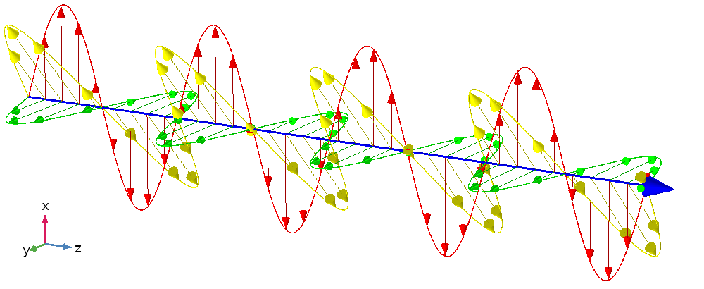
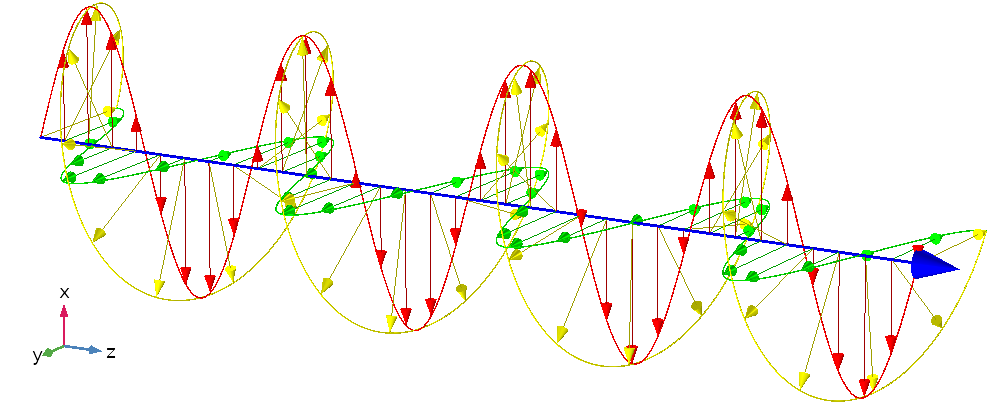
Приблизительно так обычно изображается электромагнитная волна в учебных курсах.
Почему мне захотелось ответить на этот вопрос, так это потому, что он, на самом деле, имеет двойное дно. Есть ответ очевидный и ответ, который можно дать, только обладая определёнными знаниями, выходящими за рамки школьной программы.
Но сначала договоримся, что дальше речь пойдёт только о вакууме, поскольку на распространение света в среде можно оказывать влияние электрическим или магнитным полем опосредованно через воздействие на эту среду.
Очевидный ответ
Так вот, очевидный ответ: нет, нельзя. Почему нельзя, можно объяснять по-разному в зависимости от того, как представлять свет.
Если описывать свет как электромагнитную волну, то невозможность воздействовать на него электромагнитными полями следует из линейности уравнений Максвелла, которые собственно и описывают все электромагнитные явления в классической физике. Электромагнитная волна — это одно из решений этих уравнений, а внешнее поле — это другое решение. В силу свойства линейности, их сумма также является решением уравнений Максвелла, и потому они никак друг другу «не мешают» и не оказывают друг на друга никакого воздействия.
Уравнения Максвелла в вакууме в системе СИ
Если же описывать свет как поток частиц — фотонов — то ответ объясняется тем, что фотоны не обладают электрическим зарядом, а электромагнитные поля действуют только на заряженные частицы. Интересно, что эта ситуация уникальна для электромагнитного взаимодействия. Переносчики двух других фундаментальных взаимодействий, слабого и сильного, сами также могут принимать участие в переносимом ими взаимодействии.
Кто с кем взаимодействует в Стандартной модели.
Credit: Труш Виталий // Wikimedia Commons // CC-BY-SA 3.0
Например, согласно квантовой хромодинамике, сильное взаимодействие переносится глюонами. Они осуществляют взаимодействие между частицами, обладающими так называемым цветным зарядом — аналогом электрического заряда для сильного взаимодействия. При этом глюоны и сами обладают цветным зарядом и потому взаимодействуют и между собой, и с другими частицами с цветным зарядом.
Возвратимся, однако, к нашим
баранам
фотонам.
Неочевидный ответ
Выше я уже отметил, что очевидный ответ — это лишь первый слой. Давайте снимем и второй. Так вот, неочевидный ответ — да, на свет можно воздействовать внешними полями.
Эта возможность связана с тем, что согласно квантовой электродинамике вакуум, его ещё называют квантовым вакуумом, не является абсолютной пустотой. Более того, она наполнен так называемыми виртуальными частицами, известными также как квантовые флуктуации. Их можно представлять себе как рождающиеся на короткий промежуток времени и тут же аннигилирующие пары частицы и античастицы, в первую очередь электрона и позитрона.
Картинка, поясняющая идею квантовых флуктуаций.
Credit: universe-review.ca
Если продолжить описывать квантовый вакуум в виде образов, то во внешнем электрическом (и магнитном, но остановимся только на электрическом) поле виртуальные пары начинают жить чуть дольше, поскольку электрическая сила их слегка «растаскивает». Это приводит к тому, что у вакуума появляется поляризация. А там, где есть поляризация, там есть и диэлектрическая проницаемость!
Если вы помните школьный курс оптики, то дальнейшие рассуждения для вас должны быть очевидны. Действительно, мы знаем, что изменение диэлектрической проницаемости приводит к изменению коэффициента преломления и скорости света, а это, в свою очередь, приводит к преломлению и отражению света.
Этот эффект, конечно, очень слаб, и для его наблюдения требуются совершенно фантастические по величине поля. Кроме того, наблюдать преломление света в таких полях было бы очень сложно из-за его незначительности. Несмотря на это, сейчас уже всерьёз говорят о том, чтобы лет через 10–20 наблюдать влияние поляризации вакуума на распространение света в лаборатории.
Для генерации сверхсильных полей при этом предполагается использовать лазеры сверхвысокой пиковой мощности. На данный момент построены лазеры мощностью более 1 петаватта (пета- означает множитель 1015), с их помощью было получено излучение, электрическое поле в котором достигает величины порядка 1014–1015 вольт на метр. Это всего в 1000 раз меньше так называемого швингеровского предела, при котором и становятся заметны эффекты квантовой электродинамики в вакууме.
Однако для наблюдения эффекта необязательно достигать предела, достаточно полей в десятки раз слабее. А это значит, что уже через одно-два поколения сверхмощных лазеров — при мощностях порядка 100 петаватт — в лаборатории смогут изменить направление распространения света с помощью другого света, то есть с помощью электромагнитных полей. Измерять при этом, правда, будут не направление распространения, а поляризацию света. Дело в том, что вакуум в сверхсильном поле действует как двулучепреломляющая среда. Скорости волн с разной поляризацией в такой среде различны, поэтому при распространении в ней произвольно поляризованной волны, её поляризация будет изменяться и вот это изменение измерить значительно легче.
В нашем блоге уже можно найти статьи про преломление, дисперсию и дифракцию света. Теперь пришло время поговорить о том, в чем заключается сущность поляризации света.
В самом общем смысле правильнее говорить о поляризации волн. Поляризация света, как явление, представляет собой частный случай поляризации волны. Ведь свет представляет собой электромагнитное излучение в диапазоне, воспринимаемом глазами человека.
Что такое поляризация света
Поляризация – это характеристика поперечных волн. Она описывает положение вектора колеблющейся величины в плоскости, перпендикулярной направлению распространения волны.
Если этой темы не было на лекциях в университете, то вы, вероятно, спросите: что это за колеблющаяся величина и какому направлению она перпендикулярна?
Как выглядит распространение света, если посмотреть на этот вопрос с точки зрения физики? Как, где и что колеблется, и куда при этом летит?
Свет – это электромагнитная волна, которая характеризуется векторами напряженности электрического поля E и вектором напряженности магнитного поля Н. Кстати, интересные факты о природе света можно узнать из нашей статьи.
Согласно теории Максвелла, световые волны поперечны. Это значит, что векторы E и H взаимно перпендикулярны и колеблются перпендикулярно вектору скорости распространения волны.
Поляризация наблюдается только на поперечных волнах.
Для описания поляризации света достаточно знать положение только одного из векторов. Обычно для этого рассматривается вектор E.
Если направления колебаний светового вектора каким-то образом упорядочены, свет называется поляризованным.
Возьмем свет на рисунке, который приведен выше. Он, безусловно, поляризован, так как вектор E колеблется в одной плоскости.
Если же вектор E колеблется в разных плоскостях с одинаковой вероятностью, то такой свет называется естественным.
Поляризация света по определению – это выделение из естественного света лучей с определенной ориентацией электрического вектора.
Кстати! Для наших читателей сейчас действует скидка 10% на любой вид работы
Откуда берется поляризованный свет?
Свет, который мы видим вокруг себя, чаще всего неполяризован. Свет от лампочек, солнечный свет – это свет, в котором вектор напряженности колеблется во всех возможных направлениях. Но если вам по роду деятельности приходится весь день смотреть в ЖК-монитор, знайте: вы видите поляризованный свет.
Чтобы наблюдать явление поляризации света, нужно пропустить естественный свет через анизотропную среду, которая называется поляризатором и «отсекает» ненужные направления колебаний, оставляя какое-то одно.
Анизотропная среда – среда, имеющая разные свойства в зависимости от направления внутри этой среды.
В качестве поляризаторов используются кристаллы. Один из природных кристаллов, часто и давно применяемых в опытах по изучению поляризации света — турмалин.
Еще один способ получения поляризованного света — отражение от диэлектрика. Когда свет падает на границу раздела двух сред, луч разделяется на отраженный и преломленный. При этом лучи являются частично поляризованными, а степень их поляризации зависит от угла падения.
Связь между углом падения и степенью поляризации света выражается законом Брюстера.
Когда свет падает на границу раздела под углом, тангенс которого равняется относительному показателю преломления двух сред, отраженный луч является линейно поляризованным, а преломленный луч поляризован частично с преобладанием колебаний, лежащих в плоскости падения луча.
Линейно поляризованный свет — свет, который поляризован так, что вектор E колеблется только в одной определенной плоскости.
Практическое применение явления поляризации света
Поляризация света – не просто явление, которое интересно изучать. Оно широко применяется на практике.
Пример, с которым знакомы почти все – 3D-кинематограф. Еще один пример – поляризационные очки, в которых не видно бликов солнца на воде, а свет фар встречных машин не слепит водителя. Поляризационные фильтры применяются в фототехнике, а поляризация волн используется для передачи сигналов между антеннами космических аппаратов.
Поляризация — не самое сложное для понимания природное явление. Хотя если копнуть глубоко и начать основательно разбираться с физическими законами, которым она подчиняется, могут возникнуть сложности.
Чтобы не терять время и преодолеть трудности максимально быстро, обратитесь за советом и помощью к нашим авторам. Мы поможем выполнить реферат, лабораторную работу, решить контрольные задания на тему «поляризация света».
A polarizing filter cuts down the reflections (top) and made it possible to see the photographer through the glass at roughly Brewster’s angle although reflections off the back window of the car are not cut because they are less-strongly polarized, according to the Fresnel equations.
A polarizer or polariser (see spelling differences) is an optical filter that lets light waves of a specific polarization pass through while blocking light waves of other polarizations.[1][2][3][4] It can filter a beam of light of undefined or mixed polarization into a beam of well-defined polarization, that is polarized light. The common types of polarizers are linear polarizers and circular polarizers. Polarizers are used in many optical techniques and instruments, and polarizing filters find applications in photography and LCD technology. Polarizers can also be made for other types of electromagnetic waves besides visible light, such as radio waves, microwaves, and X-rays.
Linear polarizers[edit]
Linear polarizers can be divided into two general categories: absorptive polarizers, where the unwanted polarization states are absorbed by the device, and beam-splitting polarizers, where the unpolarized beam is split into two beams with opposite polarization states. Polarizers which maintain the same axes of polarization with varying angles of incidence[clarification needed] are often called[citation needed] Cartesian polarizers, since the polarization vectors can be described with simple Cartesian coordinates (for example, horizontal vs. vertical) independent from the orientation of the polarizer surface. When the two polarization states are relative to the direction of a surface (usually found with Fresnel reflection), they are usually termed s and p. This distinction between Cartesian and s–p polarization can be negligible in many cases, but it becomes significant for achieving high contrast and with wide angular spreads of the incident light.
Absorptive polarizers[edit]
Certain crystals, due to the effects described by crystal optics, show dichroism, preferential absorption of light which is polarized in particular directions. They can therefore be used as linear polarizers. The best known crystal of this type is tourmaline. However, this crystal is seldom used as a polarizer, since the dichroic effect is strongly wavelength dependent and the crystal appears coloured. Herapathite is also dichroic, and is not strongly coloured, but is difficult to grow in large crystals.
A Polaroid polarizing filter functions similarly on an atomic scale to the wire-grid polarizer. It was originally made of microscopic herapathite crystals. Its current H-sheet form is made from polyvinyl alcohol (PVA) plastic with an iodine doping. Stretching of the sheet during manufacture causes the PVA chains to align in one particular direction. Valence electrons from the iodine dopant are able to move linearly along the polymer chains, but not transverse to them. So incident light polarized parallel to the chains is absorbed by the sheet; light polarized perpendicularly to the chains is transmitted. The durability and practicality of Polaroid makes it the most common type of polarizer in use, for example for sunglasses, photographic filters, and liquid crystal displays. It is also much cheaper than other types of polarizer.
A modern type of absorptive polarizer is made of elongated silver nano-particles embedded in thin (≤0.5 mm) glass plates. These polarizers are more durable, and can polarize light much better than plastic Polaroid film, achieving polarization ratios as high as 100,000:1 and absorption of correctly polarized light as low as 1.5%.[5] Such glass polarizers perform best for short-wavelength infrared light, and are widely used in optical fiber communications.
Beam-splitting polarizers[edit]
Beam-splitting polarizers split the incident beam into two beams of differing linear polarization. For an ideal polarizing beamsplitter these would be fully polarized, with orthogonal polarizations. For many common beam-splitting polarizers, however, only one of the two output beams is fully polarized. The other contains a mixture of polarization states.
Unlike absorptive polarizers, beam splitting polarizers do not need to absorb and dissipate the energy of the rejected polarization state, and so they are more suitable for use with high intensity beams such as laser light. True polarizing beamsplitters are also useful where the two polarization components are to be analyzed or used simultaneously.
Polarization by Fresnel reflection[edit]
A stack of plates at Brewster’s angle to a beam reflects off a fraction of the s-polarized light at each surface, leaving a p-polarized beam. Full polarization at Brewster’s angle requires many more plates than shown. The arrows indicate the direction of the electrical field, not the magnetic field, which is perpendicular to the electric field
When light reflects (by Fresnel reflection) at an angle from an interface between two transparent materials, the reflectivity is different for light polarized in the plane of incidence and light polarized perpendicular to it. Light polarized in the plane is said to be p-polarized, while that polarized perpendicular to it is s-polarized. At a special angle known as Brewster’s angle, no p-polarized light is reflected from the surface, thus all reflected light must be s-polarized, with an electric field perpendicular to the plane of incidence.
A simple linear polarizer can be made by tilting a stack of glass plates at Brewster’s angle to the beam. Some of the s-polarized light is reflected from each surface of each plate. For a stack of plates, each reflection depletes the incident beam of s-polarized light, leaving a greater fraction of p-polarized light in the transmitted beam at each stage. For visible light in air and typical glass, Brewster’s angle is about 57°, and about 16% of the s-polarized light present in the beam is reflected for each air-to-glass or glass-to-air transition. It takes many plates to achieve even mediocre polarization of the transmitted beam with this approach. For a stack of 10 plates (20 reflections), about 3% (= (1 − 0.16)20) of the s-polarized light is transmitted. The reflected beam, while fully polarized, is spread out and may not be very useful.
A more useful polarized beam can be obtained by tilting the pile of plates at a steeper angle to the incident beam. Counterintuitively, using incident angles greater than Brewster’s angle yields a higher degree of polarization of the transmitted beam, at the expense of decreased overall transmission. For angles of incidence steeper than 80° the polarization of the transmitted beam can approach 100% with as few as four plates, although the transmitted intensity is very low in this case.[6] Adding more plates and reducing the angle allows a better compromise between transmission and polarization to be achieved.
A wire-grid polarizer converts an unpolarized beam into one with a single linear polarization. Coloured arrows depict the electric field vector. The diagonally polarized waves also contribute to the transmitted polarization. Their vertical components are transmitted (shown), while the horizontal components are absorbed and reflected (not shown).
Because their polarization vectors depend on incidence angle, polarizers based on Fresnel reflection inherently tend to produce s–p polarization rather than Cartesian polarization[clarification needed], which limits their use in some applications.
Birefringent polarizers[edit]
Other linear polarizers exploit the birefringent properties of crystals such as quartz and calcite. In these crystals, a beam of unpolarized light incident on their surface is split by refraction into two rays. Snell’s law holds for both of these rays, the ordinary or o-ray, and the extraordinary or e-ray, with each ray experiencing a different index of refraction (this is called double refraction). In general the two rays will be in different polarization states, though not in linear polarization states except for certain propagation directions relative to the crystal axis.
A Nicol prism was an early type of birefringent polarizer, that consists of a crystal of calcite which has been split and rejoined with Canada balsam. The crystal is cut such that the o— and e-rays are in orthogonal linear polarization states. Total internal reflection of the o-ray occurs at the balsam interface, since it experiences a larger refractive index in calcite than in the balsam, and the ray is deflected to the side of the crystal. The e-ray, which sees a smaller refractive index in the calcite, is transmitted through the interface without deflection. Nicol prisms produce a very high purity of polarized light, and were extensively used in microscopy, though in modern use they have been mostly replaced with alternatives such as the Glan–Thompson prism, Glan–Foucault prism, and Glan–Taylor prism. These prisms are not true polarizing beamsplitters since only the transmitted beam is fully polarized.
A Wollaston prism is another birefringent polarizer consisting of two triangular calcite prisms with orthogonal crystal axes that are cemented together. At the internal interface, an unpolarized beam splits into two linearly polarized rays which leave the prism at a divergence angle of 15°–45°. The Rochon and Sénarmont prisms are similar, but use different optical axis orientations in the two prisms. The Sénarmont prism is air spaced, unlike the Wollaston and Rochon prisms. These prisms truly split the beam into two fully polarized beams with perpendicular polarizations. The Nomarski prism is a variant of the Wollaston prism, which is widely used in differential interference contrast microscopy.
Thin film polarizers[edit]
Thin-film linear polarizers (also known as TFPN) are glass substrates on which a special optical coating is applied. Either Brewster’s angle reflections or interference effects in the film cause them to act as beam-splitting polarizers. The substrate for the film can either be a plate, which is inserted into the beam at a particular angle, or a wedge of glass that is cemented to a second wedge to form a cube with the film cutting diagonally across the center (one form of this is the very common MacNeille cube[7]).
Thin-film polarizers generally do not perform as well as Glan-type polarizers, but they are inexpensive and provide two beams that are about equally well polarized. The cube-type polarizers generally perform better than the plate polarizers. The former are easily confused with Glan-type birefringent polarizers.
Wire-grid polarizers[edit]
One of the simplest linear polarizers is the wire-grid polarizer (WGP), which consists of many fine parallel metallic wires placed in a plane. WGPs mostly reflect the non-transmitted polarization and can thus be used as polarizing beam splitters. The parasitic absorption is relatively high compared to most of the dielectric polarizers though much lower than in absorptive polarizers.
Electromagnetic waves that have a component of their electric fields aligned parallel to the wires will induce the movement of electrons along the length of the wires. Since the electrons are free to move in this direction, the polarizer behaves in a similar manner to the surface of a metal when reflecting light, and the wave is reflected backwards along the incident beam (minus a small amount of energy lost to Joule heating of the wire).[8]
For waves with electric fields perpendicular to the wires, the electrons cannot move very far across the width of each wire. Therefore, little energy is reflected and the incident wave is able to pass through the grid. In this case the grid behaves like a dielectric material.
Overall, this causes the transmitted wave to be linearly polarized with an electric field completely perpendicular to the wires. The hypothesis that the waves «slip through» the gaps between the wires is incorrect.[8]
For practical purposes, the separation between wires must be less than the wavelength of the incident radiation. In addition, the width of each wire should be small compared to the spacing between wires. Therefore, it is relatively easy to construct wire-grid polarizers for microwaves, far-infrared, and mid-infrared radiation. For far-infrared optics, the polarizer can be even made as free standing mesh, entirely without transmissive optics. In addition, advanced lithographic techniques can also build very tight pitch metallic grids (typ. 50‒100 nm), allowing for the polarization of visible or infrared light to a useful degree. Since the degree of polarization depends little on wavelength and angle of incidence, they are used for broad-band applications such as projection.
Analytical solutions using rigorous coupled-wave analysis for wire grid polarizers have shown that for electric field components perpendicular to the wires, the medium behaves like a dielectric, and for electric field components parallel to the wires, the medium behaves like a metal (reflective).[9]
Malus’s law and other properties[edit]
Malus’ Law where θ1 − θ0 = θi.
Malus’ Law demonstration. No light can pass through a pair of crossed polarizing filters, but when a third filter is inserted between them with its axis not parallel to either one, some light can pass.
Malus’s law (), which is named after Étienne-Louis Malus, says that when a perfect polarizer is placed in a polarized beam of light, the irradiance, I, of the light that passes through is given by
where I0 is the initial intensity and θi is the angle between the light’s initial polarization direction and the axis of the polarizer.
A beam of unpolarized light can be thought of as containing a uniform mixture of linear polarizations at all possible angles. Since the average value of 
In practice, some light is lost in the polarizer and the actual transmission will be somewhat lower than this, around 38% for Polaroid-type polarizers but considerably higher (>49.9%) for some birefringent prism types.
If two polarizers are placed one after another (the second polarizer is generally called an analyzer), the mutual angle between their polarizing axes gives the value of θ in Malus’s law. If the two axes are orthogonal, the polarizers are crossed and in theory no light is transmitted, though again practically speaking no polarizer is perfect and the transmission is not exactly zero (for example, crossed Polaroid sheets appear slightly blue in colour because their extinction ratio is better in the red). If a transparent object is placed between the crossed polarizers, any polarization effects present in the sample (such as birefringence) will be shown as an increase in transmission. This effect is used in polarimetry to measure the optical activity of a sample.
Real polarizers are also not perfect blockers of the polarization orthogonal to their polarization axis; the ratio of the transmission of the unwanted component to the wanted component is called the extinction ratio, and varies from around 1:500 for Polaroid to about 1:106 for Glan–Taylor prism polarizers.
In X-ray the Malus’s law (relativistic form):
where 


Circular polarizers[edit]
Circular polarizers (CPL or circular polarizing filters) can be used to create circularly polarized light or alternatively to selectively absorb or pass clockwise and counter-clockwise circularly polarized light.
They are used as polarizing filters in photography to reduce oblique reflections from non-metallic surfaces, and are the lenses of the 3D glasses worn for viewing some stereoscopic movies (notably, the RealD 3D variety), where the polarization of light is used to differentiate which image should be seen by the left and right eye.
Creating circularly polarized light[edit]
Circular polarizer creating left-handed circularly polarized light. It is considered left-handed as viewed from the receiver and right-handed as viewed from the source.[11]
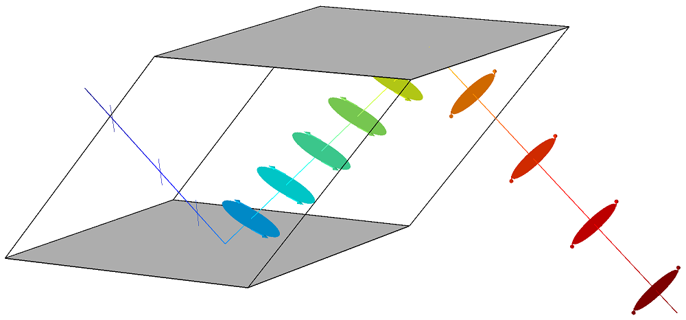
There are several ways to create circularly polarized light, the cheapest and most common involves placing a quarter-wave plate after a linear polarizer and directing unpolarized light through the linear polarizer. The linearly polarized light leaving the linear polarizer is transformed into circularly polarized light by the quarter wave plate.
The transmission axis of the linear polarizer needs to be half way (45°) between the fast and slow axes of the quarter-wave plate.
In the arrangement above, the transmission axis of the linear polarizer is at a positive 45° angle relative to the right horizontal and is represented with an orange line. The quarter-wave plate has a horizontal slow axis and a vertical fast axis and they are also represented using orange lines. In this instance the unpolarized light entering the linear polarizer is displayed as a single wave whose amplitude and angle of linear polarization are suddenly changing.
When one attempts to pass unpolarized light through the linear polarizer, only light that has its electric field at the positive 45° angle leaves the linear polarizer and enters the quarter-wave plate. In the illustration, the three wavelengths of unpolarized light represented would be transformed into the three wavelengths of linearly polarized light on the other side of the linear polarizer.
In the illustration toward the right is the electric field of the linearly polarized light just before it enters the quarter-wave plate. The red line and associated field vectors represent how the magnitude and direction of the electric field varies along the direction of travel. For this plane electromagnetic wave, each vector represents the magnitude and direction of the electric field for an entire plane that is perpendicular to the direction of travel. (Refer to these two images in the plane wave article to better appreciate this.)
Light and all other electromagnetic waves have a magnetic field which is in phase with, and perpendicular to, the electric field being displayed in these illustrations.
To understand the effect the quarter-wave plate has on the linearly polarized light it is useful to think of the light as being divided into two components which are at right angles (orthogonal) to each other. Towards this end, the blue and green lines are projections of the red line onto the vertical and horizontal planes respectively and represent how the electric field changes in the direction of those two planes. The two components have the same amplitude and are in phase.
Because the quarter-wave plate is made of a birefringent material, when in the wave plate, the light travels at different speeds depending on the direction of its electric field. This means that the horizontal component which is along the slow axis of the wave plate will travel at a slower speed than the component that is directed along the vertical fast axis. Initially the two components are in phase, but as the two components travel through the wave plate the horizontal component of the light drifts farther behind that of the vertical. By adjusting the thickness of the wave plate one can control how much the horizontal component is delayed relative to vertical component before the light leaves the wave plate and they begin again to travel at the same speed. When the light leaves the quarter-wave plate the rightward horizontal component will be exactly one quarter of a wavelength behind the vertical component making the light left-hand circularly polarized when viewed from the receiver.[11]
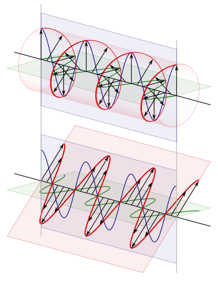
The top image is left-handed/counter-clockwise circularly polarized, as viewed from the receiver.[11] The bottom image is that of linearly polarized light. The blue and green curves are projections of the red lines on the vertical and horizontal planes respectively.
At the top of the illustration toward the right is the circularly polarized light after it leaves the wave plate. Directly below it, for comparison purposes, is the linearly polarized light that entered the quarter-wave plate. In the upper image, because this is a plane wave, each vector leading from the axis to the helix represents the magnitude and direction of the electric field for an entire plane that is perpendicular to the direction of travel. All the electric field vectors have the same magnitude indicating that the strength of the electric field does not change. The direction of the electric field however steadily rotates.
The blue and green lines are projections of the helix onto the vertical and horizontal planes respectively and represent how the electric field changes in the direction of those two planes. Notice how the rightward horizontal component is now one quarter of a wavelength behind the vertical component. It is this quarter of a wavelength phase shift that results in the rotational nature of the electric field. It is significant to note that when the magnitude of one component is at a maximum the magnitude of the other component is always zero. This is the reason that there are helix vectors which exactly correspond to the maxima of the two components.
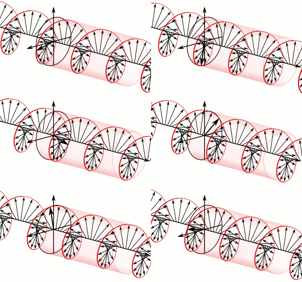
Animation of left-handed/counter-clockwise circularly polarized light. (Left-handed as viewed from the receiver.[11])
In the instance just cited, using the handedness convention used in many optics textbooks, the light is considered left-handed/counter-clockwise circularly polarized. Referring to the accompanying animation, it is considered left-handed because if one points one’s left thumb against the direction of travel, ones fingers curl in the direction the electric field rotates as the wave passes a given point in space. The helix also forms a left-handed helix in space. Similarly this light is considered counter-clockwise circularly polarized because if a stationary observer faces against the direction of travel, the person will observe its electric field rotate in the counter-clockwise direction as the wave passes a given point in space.[11]
To create right-handed, clockwise circularly polarized light one simply rotates the axis of the quarter-wave plate 90° relative to the linear polarizer. This reverses the fast and slow axes of the wave plate relative to the transmission axis of the linear polarizer reversing which component leads and which component lags.
In trying to appreciate how the quarter-wave plate transforms the linearly polarized light, it is important to realize that the two components discussed are not entities in and of themselves but are merely mental constructs one uses to help appreciate what is happening. In the case of linearly and circularly polarized light, at each point in space, there is always a single electric field with a distinct vector direction, the quarter-wave plate merely has the effect of transforming this single electric field.
Absorbing and passing circularly polarized light[edit]
Circular polarizers can also be used to selectively absorb or pass right-handed or left-handed circularly polarized light. It is this feature which is utilized by the 3D glasses in stereoscopic cinemas such as RealD Cinema. A given polarizer which creates one of the two polarizations of light will pass that same polarization of light when that light is sent through it in the other direction. In contrast it will block light of the opposite polarization.
Circular polarizer passing left-handed, counter-clockwise circularly polarized light. (Left-handed as viewed from the receiver.)[11]
The illustration above is identical to the previous similar one with the exception that the left-handed circularly polarized light is now approaching the polarizer from the opposite direction and linearly polarized light is exiting the polarizer toward the right.
First note that a quarter-wave plate always transforms circularly polarized light into linearly polarized light. It is only the resulting angle of polarization of the linearly polarized light that is determined by the orientation of the fast and slow axes of the quarter-wave plate and the handedness of the circularly polarized light. In the illustration, the left-handed circularly polarized light entering the polarizer is transformed into linearly polarized light which has its direction of polarization along the transmission axis of the linear polarizer and it therefore passes. In contrast right-handed circularly polarized light would have been transformed into linearly polarized light that had its direction of polarization along the absorbing axis of the linear polarizer, which is at right angles to the transmission axis, and it would have therefore been blocked.
Left-handed/Counter-Clockwise circularly polarized light displayed above linearly polarized light.[11] The blue and green curves are projections of the helix on the vertical and horizontal planes respectively.
To understand this process, refer to the illustration on the right. It is absolutely identical to the earlier illustration even though the circularly polarized light at the top is now considered to be approaching the polarizer from the left. One can observe from the illustration that the leftward horizontal (as observed looking along the direction of travel) component is leading the vertical component and that when the horizontal component is retarded by one quarter of a wavelength it will be transformed into the linearly polarized light illustrated at the bottom and it will pass through the linear polarizer.
There is a relatively straightforward way to appreciate why a polarizer which creates a given handedness of circularly polarized light also passes that same handedness of polarized light. First, given the dual usefulness of this image, begin by imagining the circularly polarized light displayed at the top as still leaving the quarter-wave plate and traveling toward the left. Observe that had the horizontal component of the linearly polarized light been retarded by a quarter of wavelength twice, which would amount to a full half wavelength, the result would have been linearly polarized light that was at a right angle to the light that entered. If such orthogonally polarized light were rotated on the horizontal plane and directed back through the linear polarizer section of the circular polarizer it would clearly pass through given its orientation. Now imagine the circularly polarized light which has already passed through the quarter-wave plate once, turned around and directed back toward the circular polarizer again. Let the circularly polarized light illustrated at the top now represent that light. Such light is going to travel through the quarter-wave plate a second time before reaching the linear polarizer and in the process, its horizontal component is going to be retarded a second time by one quarter of a wavelength. Whether that horizontal component is retarded by one quarter of a wavelength in two distinct steps or retarded a full half wavelength all at once, the orientation of the resulting linearly polarized light will be such that it passes through the linear polarizer.
Had it been right-handed, clockwise circularly polarized light approaching the circular polarizer from the left, its horizontal component would have also been retarded, however the resulting linearly polarized light would have been polarized along the absorbing axis of the linear polarizer and it would not have passed.
To create a circular polarizer that instead passes right-handed polarized light and absorbs left-handed light, one again rotates the wave plate and linear polarizer 90° relative to each another. It is easy to appreciate that by reversing the positions of the transmitting and absorbing axes of the linear polarizer relative to the quarter-wave plate, one changes which handedness of polarized light gets transmitted and which gets absorbed.
Homogeneous circular polarizer[edit]
Homogeneous circular polarizer passing left-handed, counter-clockwise circularly polarized light. (Left-handed as viewed from the receiver.)[11]
A homogeneous circular polarizer passes one handedness of circular polarization unaltered and blocks the other handedness. This is similar to the way that a linear polarizer would fully pass one angle of linearly polarized light unaltered, but would fully block any linearly polarized light that was orthogonal to it.
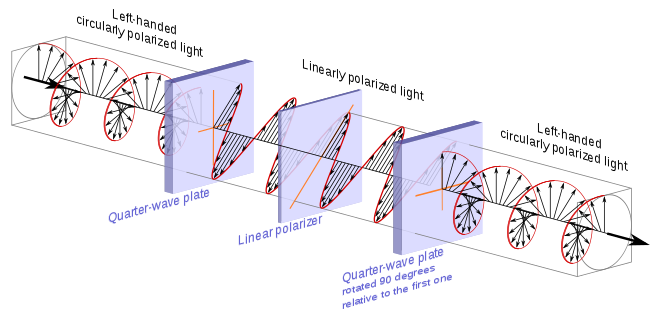
A homogeneous circular polarizer can be created by sandwiching a linear polarizer between two quarter-wave plates.[12] Specifically we take the circular polarizer described previously, which transforms circularly polarized light into linear polarized light, and add to it a second quarter-wave plate rotated 90° relative to the first one.
Generally speaking, and not making direct reference to the above illustration, when either of the two polarizations of circularly polarized light enters the first quarter-wave plate, one of a pair of orthogonal components is retarded by one quarter of a wavelength relative to the other. This creates one of two linear polarizations depending on the handedness the circularly polarized light. The linear polarizer sandwiched between the quarter wave plates is oriented so that it will pass one linear polarization and block the other. The second quarter-wave plate then takes the linearly polarized light that passes and retards the orthogonal component that was not retarded by the previous quarter-wave plate. This brings the two components back into their initial phase relationship, reestablishing the selected circular polarization.
Note that it does not matter in which direction one passes the circularly polarized light.
Circular and linear polarizing filters for photography[edit]
Linear polarizing filters were the first types to be used in photography and can still be used for non-reflex and older single-lens reflex cameras (SLRs). However, cameras with through-the-lens metering (TTL) and autofocusing systems – that is, all modern SLR and DSLR – rely on optical elements that pass linearly polarized light. If light entering the camera is already linearly polarized, it can upset the exposure or autofocus systems. Circular polarizing filters cut out linearly polarized light and so can be used to darken skies, improve saturation and remove reflections, but the circular polarized light it passes does not impair through-the-lens systems.[13]
See also[edit]
- Photoelastic modulator – a wave plate that can rapidly switch fast and slow axes, and thus produce rapidly alternating left and right circular polarization. They commonly operate in the ultrasonic range
- Fresnel rhomb – another way of producing circularly polarized light; it does not use a wave plate
- Extinction cross
- Poincaré sphere (optics)
- Edwin Land
- Polariscope
- Polarized light microscope
- Geometric Phase Lens
References[edit]
- ^ Wolf, Mark J. P. (2008). The Video Game Explosion: A History from PONG to Playstation and Beyond. ABC-CLIO. p. 315. ISBN 978-0313338687.
- ^ Johnsen, Sönke (2012). The Optics of Life: A Biologist’s Guide to Light in Nature. Princeton Univ. Press. pp. 207–208. ISBN 978-0691139913.
- ^ Basu, Dipak (2000). Dictionary of Pure and Applied Physics. CRC Press. pp. 142–143. ISBN 1420050222.
- ^ Gåsvik, Kjell J. (2003). Optical Metrology (3rd ed.). John Wiley and Sons. pp. 219–221. ISBN 0470846704.
- ^ «Polarcor glass polarizers: Product information» (PDF). Corning.com. December 2006. Archived from the original (PDF) on 2007-10-12. Retrieved 2008-08-08.
- ^ Collett, Edward. Field Guide to Polarization, SPIE Field Guides vol. FG05, SPIE (2005) ISBN 0-8194-5868-6.
- ^ US patent 2,403,731, Stephen M. MacNeille, «Beam splitter», issued 1946-June-4
- ^ a b Hecht, Eugene. Optics, 2nd ed., Addison Wesley (1990) ISBN 0-201-11609-X. Chapter 8.
- ^ Yu, X. J.; Kwok, H. S. (2003). «Optical wire-grid polarizers at oblique angles of incidence» (PDF). Journal of Applied Physics. 93 (8): 4407. Bibcode:2003JAP….93.4407Y. doi:10.1063/1.1559937. ISSN 0021-8979. S2CID 13921545. Archived from the original (PDF) on 2019-12-20.
- ^ A. N. Volobuev (2013). Interaction of the Electromagnetic Field with Substance. New York: Nova Science Publishers, Inc. ISBN 978-1-62618-348-3.
- ^ a b c d e f g h Refer to well referenced section in Circular Polarization article for a discussion of handedness. Left/Right Handedness
- ^ Bass M (1995) Handbook of Optics, Second edition, Vol. 2, Ch. 22.19, McGraw-Hill, ISBN 0-07-047974-7
- ^ Ang, Tom (2008).Fundamentals of Modern Photography. Octopus Publishing Group Limited. p168. ISBN 978-1-84533-2310.
Further reading[edit]
- Kliger, David S. Polarized Light in Optics and Spectroscopy, Academic Press (1990), ISBN 0-12-414975-8
- Mann, James. «Austine Wood Comarow: Paintings in Polarized Light», Wasabi Publishing (2005), ISBN 978-0976819806
External links[edit]
Media related to Polarization at Wikimedia Commons
A polarizing filter cuts down the reflections (top) and made it possible to see the photographer through the glass at roughly Brewster’s angle although reflections off the back window of the car are not cut because they are less-strongly polarized, according to the Fresnel equations.
A polarizer or polariser (see spelling differences) is an optical filter that lets light waves of a specific polarization pass through while blocking light waves of other polarizations.[1][2][3][4] It can filter a beam of light of undefined or mixed polarization into a beam of well-defined polarization, that is polarized light. The common types of polarizers are linear polarizers and circular polarizers. Polarizers are used in many optical techniques and instruments, and polarizing filters find applications in photography and LCD technology. Polarizers can also be made for other types of electromagnetic waves besides visible light, such as radio waves, microwaves, and X-rays.
Linear polarizers[edit]
Linear polarizers can be divided into two general categories: absorptive polarizers, where the unwanted polarization states are absorbed by the device, and beam-splitting polarizers, where the unpolarized beam is split into two beams with opposite polarization states. Polarizers which maintain the same axes of polarization with varying angles of incidence[clarification needed] are often called[citation needed] Cartesian polarizers, since the polarization vectors can be described with simple Cartesian coordinates (for example, horizontal vs. vertical) independent from the orientation of the polarizer surface. When the two polarization states are relative to the direction of a surface (usually found with Fresnel reflection), they are usually termed s and p. This distinction between Cartesian and s–p polarization can be negligible in many cases, but it becomes significant for achieving high contrast and with wide angular spreads of the incident light.
Absorptive polarizers[edit]
Certain crystals, due to the effects described by crystal optics, show dichroism, preferential absorption of light which is polarized in particular directions. They can therefore be used as linear polarizers. The best known crystal of this type is tourmaline. However, this crystal is seldom used as a polarizer, since the dichroic effect is strongly wavelength dependent and the crystal appears coloured. Herapathite is also dichroic, and is not strongly coloured, but is difficult to grow in large crystals.
A Polaroid polarizing filter functions similarly on an atomic scale to the wire-grid polarizer. It was originally made of microscopic herapathite crystals. Its current H-sheet form is made from polyvinyl alcohol (PVA) plastic with an iodine doping. Stretching of the sheet during manufacture causes the PVA chains to align in one particular direction. Valence electrons from the iodine dopant are able to move linearly along the polymer chains, but not transverse to them. So incident light polarized parallel to the chains is absorbed by the sheet; light polarized perpendicularly to the chains is transmitted. The durability and practicality of Polaroid makes it the most common type of polarizer in use, for example for sunglasses, photographic filters, and liquid crystal displays. It is also much cheaper than other types of polarizer.
A modern type of absorptive polarizer is made of elongated silver nano-particles embedded in thin (≤0.5 mm) glass plates. These polarizers are more durable, and can polarize light much better than plastic Polaroid film, achieving polarization ratios as high as 100,000:1 and absorption of correctly polarized light as low as 1.5%.[5] Such glass polarizers perform best for short-wavelength infrared light, and are widely used in optical fiber communications.
Beam-splitting polarizers[edit]
Beam-splitting polarizers split the incident beam into two beams of differing linear polarization. For an ideal polarizing beamsplitter these would be fully polarized, with orthogonal polarizations. For many common beam-splitting polarizers, however, only one of the two output beams is fully polarized. The other contains a mixture of polarization states.
Unlike absorptive polarizers, beam splitting polarizers do not need to absorb and dissipate the energy of the rejected polarization state, and so they are more suitable for use with high intensity beams such as laser light. True polarizing beamsplitters are also useful where the two polarization components are to be analyzed or used simultaneously.
Polarization by Fresnel reflection[edit]
A stack of plates at Brewster’s angle to a beam reflects off a fraction of the s-polarized light at each surface, leaving a p-polarized beam. Full polarization at Brewster’s angle requires many more plates than shown. The arrows indicate the direction of the electrical field, not the magnetic field, which is perpendicular to the electric field
When light reflects (by Fresnel reflection) at an angle from an interface between two transparent materials, the reflectivity is different for light polarized in the plane of incidence and light polarized perpendicular to it. Light polarized in the plane is said to be p-polarized, while that polarized perpendicular to it is s-polarized. At a special angle known as Brewster’s angle, no p-polarized light is reflected from the surface, thus all reflected light must be s-polarized, with an electric field perpendicular to the plane of incidence.
A simple linear polarizer can be made by tilting a stack of glass plates at Brewster’s angle to the beam. Some of the s-polarized light is reflected from each surface of each plate. For a stack of plates, each reflection depletes the incident beam of s-polarized light, leaving a greater fraction of p-polarized light in the transmitted beam at each stage. For visible light in air and typical glass, Brewster’s angle is about 57°, and about 16% of the s-polarized light present in the beam is reflected for each air-to-glass or glass-to-air transition. It takes many plates to achieve even mediocre polarization of the transmitted beam with this approach. For a stack of 10 plates (20 reflections), about 3% (= (1 − 0.16)20) of the s-polarized light is transmitted. The reflected beam, while fully polarized, is spread out and may not be very useful.
A more useful polarized beam can be obtained by tilting the pile of plates at a steeper angle to the incident beam. Counterintuitively, using incident angles greater than Brewster’s angle yields a higher degree of polarization of the transmitted beam, at the expense of decreased overall transmission. For angles of incidence steeper than 80° the polarization of the transmitted beam can approach 100% with as few as four plates, although the transmitted intensity is very low in this case.[6] Adding more plates and reducing the angle allows a better compromise between transmission and polarization to be achieved.
A wire-grid polarizer converts an unpolarized beam into one with a single linear polarization. Coloured arrows depict the electric field vector. The diagonally polarized waves also contribute to the transmitted polarization. Their vertical components are transmitted (shown), while the horizontal components are absorbed and reflected (not shown).
Because their polarization vectors depend on incidence angle, polarizers based on Fresnel reflection inherently tend to produce s–p polarization rather than Cartesian polarization[clarification needed], which limits their use in some applications.
Birefringent polarizers[edit]
Other linear polarizers exploit the birefringent properties of crystals such as quartz and calcite. In these crystals, a beam of unpolarized light incident on their surface is split by refraction into two rays. Snell’s law holds for both of these rays, the ordinary or o-ray, and the extraordinary or e-ray, with each ray experiencing a different index of refraction (this is called double refraction). In general the two rays will be in different polarization states, though not in linear polarization states except for certain propagation directions relative to the crystal axis.
A Nicol prism was an early type of birefringent polarizer, that consists of a crystal of calcite which has been split and rejoined with Canada balsam. The crystal is cut such that the o— and e-rays are in orthogonal linear polarization states. Total internal reflection of the o-ray occurs at the balsam interface, since it experiences a larger refractive index in calcite than in the balsam, and the ray is deflected to the side of the crystal. The e-ray, which sees a smaller refractive index in the calcite, is transmitted through the interface without deflection. Nicol prisms produce a very high purity of polarized light, and were extensively used in microscopy, though in modern use they have been mostly replaced with alternatives such as the Glan–Thompson prism, Glan–Foucault prism, and Glan–Taylor prism. These prisms are not true polarizing beamsplitters since only the transmitted beam is fully polarized.
A Wollaston prism is another birefringent polarizer consisting of two triangular calcite prisms with orthogonal crystal axes that are cemented together. At the internal interface, an unpolarized beam splits into two linearly polarized rays which leave the prism at a divergence angle of 15°–45°. The Rochon and Sénarmont prisms are similar, but use different optical axis orientations in the two prisms. The Sénarmont prism is air spaced, unlike the Wollaston and Rochon prisms. These prisms truly split the beam into two fully polarized beams with perpendicular polarizations. The Nomarski prism is a variant of the Wollaston prism, which is widely used in differential interference contrast microscopy.
Thin film polarizers[edit]
Thin-film linear polarizers (also known as TFPN) are glass substrates on which a special optical coating is applied. Either Brewster’s angle reflections or interference effects in the film cause them to act as beam-splitting polarizers. The substrate for the film can either be a plate, which is inserted into the beam at a particular angle, or a wedge of glass that is cemented to a second wedge to form a cube with the film cutting diagonally across the center (one form of this is the very common MacNeille cube[7]).
Thin-film polarizers generally do not perform as well as Glan-type polarizers, but they are inexpensive and provide two beams that are about equally well polarized. The cube-type polarizers generally perform better than the plate polarizers. The former are easily confused with Glan-type birefringent polarizers.
Wire-grid polarizers[edit]
One of the simplest linear polarizers is the wire-grid polarizer (WGP), which consists of many fine parallel metallic wires placed in a plane. WGPs mostly reflect the non-transmitted polarization and can thus be used as polarizing beam splitters. The parasitic absorption is relatively high compared to most of the dielectric polarizers though much lower than in absorptive polarizers.
Electromagnetic waves that have a component of their electric fields aligned parallel to the wires will induce the movement of electrons along the length of the wires. Since the electrons are free to move in this direction, the polarizer behaves in a similar manner to the surface of a metal when reflecting light, and the wave is reflected backwards along the incident beam (minus a small amount of energy lost to Joule heating of the wire).[8]
For waves with electric fields perpendicular to the wires, the electrons cannot move very far across the width of each wire. Therefore, little energy is reflected and the incident wave is able to pass through the grid. In this case the grid behaves like a dielectric material.
Overall, this causes the transmitted wave to be linearly polarized with an electric field completely perpendicular to the wires. The hypothesis that the waves «slip through» the gaps between the wires is incorrect.[8]
For practical purposes, the separation between wires must be less than the wavelength of the incident radiation. In addition, the width of each wire should be small compared to the spacing between wires. Therefore, it is relatively easy to construct wire-grid polarizers for microwaves, far-infrared, and mid-infrared radiation. For far-infrared optics, the polarizer can be even made as free standing mesh, entirely without transmissive optics. In addition, advanced lithographic techniques can also build very tight pitch metallic grids (typ. 50‒100 nm), allowing for the polarization of visible or infrared light to a useful degree. Since the degree of polarization depends little on wavelength and angle of incidence, they are used for broad-band applications such as projection.
Analytical solutions using rigorous coupled-wave analysis for wire grid polarizers have shown that for electric field components perpendicular to the wires, the medium behaves like a dielectric, and for electric field components parallel to the wires, the medium behaves like a metal (reflective).[9]
Malus’s law and other properties[edit]
Malus’ Law where θ1 − θ0 = θi.
Malus’ Law demonstration. No light can pass through a pair of crossed polarizing filters, but when a third filter is inserted between them with its axis not parallel to either one, some light can pass.
Malus’s law (), which is named after Étienne-Louis Malus, says that when a perfect polarizer is placed in a polarized beam of light, the irradiance, I, of the light that passes through is given by
where I0 is the initial intensity and θi is the angle between the light’s initial polarization direction and the axis of the polarizer.
A beam of unpolarized light can be thought of as containing a uniform mixture of linear polarizations at all possible angles. Since the average value of 
In practice, some light is lost in the polarizer and the actual transmission will be somewhat lower than this, around 38% for Polaroid-type polarizers but considerably higher (>49.9%) for some birefringent prism types.
If two polarizers are placed one after another (the second polarizer is generally called an analyzer), the mutual angle between their polarizing axes gives the value of θ in Malus’s law. If the two axes are orthogonal, the polarizers are crossed and in theory no light is transmitted, though again practically speaking no polarizer is perfect and the transmission is not exactly zero (for example, crossed Polaroid sheets appear slightly blue in colour because their extinction ratio is better in the red). If a transparent object is placed between the crossed polarizers, any polarization effects present in the sample (such as birefringence) will be shown as an increase in transmission. This effect is used in polarimetry to measure the optical activity of a sample.
Real polarizers are also not perfect blockers of the polarization orthogonal to their polarization axis; the ratio of the transmission of the unwanted component to the wanted component is called the extinction ratio, and varies from around 1:500 for Polaroid to about 1:106 for Glan–Taylor prism polarizers.
In X-ray the Malus’s law (relativistic form):
where 


Circular polarizers[edit]
Circular polarizers (CPL or circular polarizing filters) can be used to create circularly polarized light or alternatively to selectively absorb or pass clockwise and counter-clockwise circularly polarized light.
They are used as polarizing filters in photography to reduce oblique reflections from non-metallic surfaces, and are the lenses of the 3D glasses worn for viewing some stereoscopic movies (notably, the RealD 3D variety), where the polarization of light is used to differentiate which image should be seen by the left and right eye.
Creating circularly polarized light[edit]
Circular polarizer creating left-handed circularly polarized light. It is considered left-handed as viewed from the receiver and right-handed as viewed from the source.[11]
There are several ways to create circularly polarized light, the cheapest and most common involves placing a quarter-wave plate after a linear polarizer and directing unpolarized light through the linear polarizer. The linearly polarized light leaving the linear polarizer is transformed into circularly polarized light by the quarter wave plate.
The transmission axis of the linear polarizer needs to be half way (45°) between the fast and slow axes of the quarter-wave plate.
In the arrangement above, the transmission axis of the linear polarizer is at a positive 45° angle relative to the right horizontal and is represented with an orange line. The quarter-wave plate has a horizontal slow axis and a vertical fast axis and they are also represented using orange lines. In this instance the unpolarized light entering the linear polarizer is displayed as a single wave whose amplitude and angle of linear polarization are suddenly changing.
When one attempts to pass unpolarized light through the linear polarizer, only light that has its electric field at the positive 45° angle leaves the linear polarizer and enters the quarter-wave plate. In the illustration, the three wavelengths of unpolarized light represented would be transformed into the three wavelengths of linearly polarized light on the other side of the linear polarizer.
In the illustration toward the right is the electric field of the linearly polarized light just before it enters the quarter-wave plate. The red line and associated field vectors represent how the magnitude and direction of the electric field varies along the direction of travel. For this plane electromagnetic wave, each vector represents the magnitude and direction of the electric field for an entire plane that is perpendicular to the direction of travel. (Refer to these two images in the plane wave article to better appreciate this.)
Light and all other electromagnetic waves have a magnetic field which is in phase with, and perpendicular to, the electric field being displayed in these illustrations.
To understand the effect the quarter-wave plate has on the linearly polarized light it is useful to think of the light as being divided into two components which are at right angles (orthogonal) to each other. Towards this end, the blue and green lines are projections of the red line onto the vertical and horizontal planes respectively and represent how the electric field changes in the direction of those two planes. The two components have the same amplitude and are in phase.
Because the quarter-wave plate is made of a birefringent material, when in the wave plate, the light travels at different speeds depending on the direction of its electric field. This means that the horizontal component which is along the slow axis of the wave plate will travel at a slower speed than the component that is directed along the vertical fast axis. Initially the two components are in phase, but as the two components travel through the wave plate the horizontal component of the light drifts farther behind that of the vertical. By adjusting the thickness of the wave plate one can control how much the horizontal component is delayed relative to vertical component before the light leaves the wave plate and they begin again to travel at the same speed. When the light leaves the quarter-wave plate the rightward horizontal component will be exactly one quarter of a wavelength behind the vertical component making the light left-hand circularly polarized when viewed from the receiver.[11]
The top image is left-handed/counter-clockwise circularly polarized, as viewed from the receiver.[11] The bottom image is that of linearly polarized light. The blue and green curves are projections of the red lines on the vertical and horizontal planes respectively.
At the top of the illustration toward the right is the circularly polarized light after it leaves the wave plate. Directly below it, for comparison purposes, is the linearly polarized light that entered the quarter-wave plate. In the upper image, because this is a plane wave, each vector leading from the axis to the helix represents the magnitude and direction of the electric field for an entire plane that is perpendicular to the direction of travel. All the electric field vectors have the same magnitude indicating that the strength of the electric field does not change. The direction of the electric field however steadily rotates.
The blue and green lines are projections of the helix onto the vertical and horizontal planes respectively and represent how the electric field changes in the direction of those two planes. Notice how the rightward horizontal component is now one quarter of a wavelength behind the vertical component. It is this quarter of a wavelength phase shift that results in the rotational nature of the electric field. It is significant to note that when the magnitude of one component is at a maximum the magnitude of the other component is always zero. This is the reason that there are helix vectors which exactly correspond to the maxima of the two components.
Animation of left-handed/counter-clockwise circularly polarized light. (Left-handed as viewed from the receiver.[11])
In the instance just cited, using the handedness convention used in many optics textbooks, the light is considered left-handed/counter-clockwise circularly polarized. Referring to the accompanying animation, it is considered left-handed because if one points one’s left thumb against the direction of travel, ones fingers curl in the direction the electric field rotates as the wave passes a given point in space. The helix also forms a left-handed helix in space. Similarly this light is considered counter-clockwise circularly polarized because if a stationary observer faces against the direction of travel, the person will observe its electric field rotate in the counter-clockwise direction as the wave passes a given point in space.[11]
To create right-handed, clockwise circularly polarized light one simply rotates the axis of the quarter-wave plate 90° relative to the linear polarizer. This reverses the fast and slow axes of the wave plate relative to the transmission axis of the linear polarizer reversing which component leads and which component lags.
In trying to appreciate how the quarter-wave plate transforms the linearly polarized light, it is important to realize that the two components discussed are not entities in and of themselves but are merely mental constructs one uses to help appreciate what is happening. In the case of linearly and circularly polarized light, at each point in space, there is always a single electric field with a distinct vector direction, the quarter-wave plate merely has the effect of transforming this single electric field.
Absorbing and passing circularly polarized light[edit]
Circular polarizers can also be used to selectively absorb or pass right-handed or left-handed circularly polarized light. It is this feature which is utilized by the 3D glasses in stereoscopic cinemas such as RealD Cinema. A given polarizer which creates one of the two polarizations of light will pass that same polarization of light when that light is sent through it in the other direction. In contrast it will block light of the opposite polarization.
Circular polarizer passing left-handed, counter-clockwise circularly polarized light. (Left-handed as viewed from the receiver.)[11]
The illustration above is identical to the previous similar one with the exception that the left-handed circularly polarized light is now approaching the polarizer from the opposite direction and linearly polarized light is exiting the polarizer toward the right.
First note that a quarter-wave plate always transforms circularly polarized light into linearly polarized light. It is only the resulting angle of polarization of the linearly polarized light that is determined by the orientation of the fast and slow axes of the quarter-wave plate and the handedness of the circularly polarized light. In the illustration, the left-handed circularly polarized light entering the polarizer is transformed into linearly polarized light which has its direction of polarization along the transmission axis of the linear polarizer and it therefore passes. In contrast right-handed circularly polarized light would have been transformed into linearly polarized light that had its direction of polarization along the absorbing axis of the linear polarizer, which is at right angles to the transmission axis, and it would have therefore been blocked.
Left-handed/Counter-Clockwise circularly polarized light displayed above linearly polarized light.[11] The blue and green curves are projections of the helix on the vertical and horizontal planes respectively.
To understand this process, refer to the illustration on the right. It is absolutely identical to the earlier illustration even though the circularly polarized light at the top is now considered to be approaching the polarizer from the left. One can observe from the illustration that the leftward horizontal (as observed looking along the direction of travel) component is leading the vertical component and that when the horizontal component is retarded by one quarter of a wavelength it will be transformed into the linearly polarized light illustrated at the bottom and it will pass through the linear polarizer.
There is a relatively straightforward way to appreciate why a polarizer which creates a given handedness of circularly polarized light also passes that same handedness of polarized light. First, given the dual usefulness of this image, begin by imagining the circularly polarized light displayed at the top as still leaving the quarter-wave plate and traveling toward the left. Observe that had the horizontal component of the linearly polarized light been retarded by a quarter of wavelength twice, which would amount to a full half wavelength, the result would have been linearly polarized light that was at a right angle to the light that entered. If such orthogonally polarized light were rotated on the horizontal plane and directed back through the linear polarizer section of the circular polarizer it would clearly pass through given its orientation. Now imagine the circularly polarized light which has already passed through the quarter-wave plate once, turned around and directed back toward the circular polarizer again. Let the circularly polarized light illustrated at the top now represent that light. Such light is going to travel through the quarter-wave plate a second time before reaching the linear polarizer and in the process, its horizontal component is going to be retarded a second time by one quarter of a wavelength. Whether that horizontal component is retarded by one quarter of a wavelength in two distinct steps or retarded a full half wavelength all at once, the orientation of the resulting linearly polarized light will be such that it passes through the linear polarizer.
Had it been right-handed, clockwise circularly polarized light approaching the circular polarizer from the left, its horizontal component would have also been retarded, however the resulting linearly polarized light would have been polarized along the absorbing axis of the linear polarizer and it would not have passed.
To create a circular polarizer that instead passes right-handed polarized light and absorbs left-handed light, one again rotates the wave plate and linear polarizer 90° relative to each another. It is easy to appreciate that by reversing the positions of the transmitting and absorbing axes of the linear polarizer relative to the quarter-wave plate, one changes which handedness of polarized light gets transmitted and which gets absorbed.
Homogeneous circular polarizer[edit]
Homogeneous circular polarizer passing left-handed, counter-clockwise circularly polarized light. (Left-handed as viewed from the receiver.)[11]
A homogeneous circular polarizer passes one handedness of circular polarization unaltered and blocks the other handedness. This is similar to the way that a linear polarizer would fully pass one angle of linearly polarized light unaltered, but would fully block any linearly polarized light that was orthogonal to it.
A homogeneous circular polarizer can be created by sandwiching a linear polarizer between two quarter-wave plates.[12] Specifically we take the circular polarizer described previously, which transforms circularly polarized light into linear polarized light, and add to it a second quarter-wave plate rotated 90° relative to the first one.
Generally speaking, and not making direct reference to the above illustration, when either of the two polarizations of circularly polarized light enters the first quarter-wave plate, one of a pair of orthogonal components is retarded by one quarter of a wavelength relative to the other. This creates one of two linear polarizations depending on the handedness the circularly polarized light. The linear polarizer sandwiched between the quarter wave plates is oriented so that it will pass one linear polarization and block the other. The second quarter-wave plate then takes the linearly polarized light that passes and retards the orthogonal component that was not retarded by the previous quarter-wave plate. This brings the two components back into their initial phase relationship, reestablishing the selected circular polarization.
Note that it does not matter in which direction one passes the circularly polarized light.
Circular and linear polarizing filters for photography[edit]
Linear polarizing filters were the first types to be used in photography and can still be used for non-reflex and older single-lens reflex cameras (SLRs). However, cameras with through-the-lens metering (TTL) and autofocusing systems – that is, all modern SLR and DSLR – rely on optical elements that pass linearly polarized light. If light entering the camera is already linearly polarized, it can upset the exposure or autofocus systems. Circular polarizing filters cut out linearly polarized light and so can be used to darken skies, improve saturation and remove reflections, but the circular polarized light it passes does not impair through-the-lens systems.[13]
See also[edit]
- Photoelastic modulator – a wave plate that can rapidly switch fast and slow axes, and thus produce rapidly alternating left and right circular polarization. They commonly operate in the ultrasonic range
- Fresnel rhomb – another way of producing circularly polarized light; it does not use a wave plate
- Extinction cross
- Poincaré sphere (optics)
- Edwin Land
- Polariscope
- Polarized light microscope
- Geometric Phase Lens
References[edit]
- ^ Wolf, Mark J. P. (2008). The Video Game Explosion: A History from PONG to Playstation and Beyond. ABC-CLIO. p. 315. ISBN 978-0313338687.
- ^ Johnsen, Sönke (2012). The Optics of Life: A Biologist’s Guide to Light in Nature. Princeton Univ. Press. pp. 207–208. ISBN 978-0691139913.
- ^ Basu, Dipak (2000). Dictionary of Pure and Applied Physics. CRC Press. pp. 142–143. ISBN 1420050222.
- ^ Gåsvik, Kjell J. (2003). Optical Metrology (3rd ed.). John Wiley and Sons. pp. 219–221. ISBN 0470846704.
- ^ «Polarcor glass polarizers: Product information» (PDF). Corning.com. December 2006. Archived from the original (PDF) on 2007-10-12. Retrieved 2008-08-08.
- ^ Collett, Edward. Field Guide to Polarization, SPIE Field Guides vol. FG05, SPIE (2005) ISBN 0-8194-5868-6.
- ^ US patent 2,403,731, Stephen M. MacNeille, «Beam splitter», issued 1946-June-4
- ^ a b Hecht, Eugene. Optics, 2nd ed., Addison Wesley (1990) ISBN 0-201-11609-X. Chapter 8.
- ^ Yu, X. J.; Kwok, H. S. (2003). «Optical wire-grid polarizers at oblique angles of incidence» (PDF). Journal of Applied Physics. 93 (8): 4407. Bibcode:2003JAP….93.4407Y. doi:10.1063/1.1559937. ISSN 0021-8979. S2CID 13921545. Archived from the original (PDF) on 2019-12-20.
- ^ A. N. Volobuev (2013). Interaction of the Electromagnetic Field with Substance. New York: Nova Science Publishers, Inc. ISBN 978-1-62618-348-3.
- ^ a b c d e f g h Refer to well referenced section in Circular Polarization article for a discussion of handedness. Left/Right Handedness
- ^ Bass M (1995) Handbook of Optics, Second edition, Vol. 2, Ch. 22.19, McGraw-Hill, ISBN 0-07-047974-7
- ^ Ang, Tom (2008).Fundamentals of Modern Photography. Octopus Publishing Group Limited. p168. ISBN 978-1-84533-2310.
Further reading[edit]
- Kliger, David S. Polarized Light in Optics and Spectroscopy, Academic Press (1990), ISBN 0-12-414975-8
- Mann, James. «Austine Wood Comarow: Paintings in Polarized Light», Wasabi Publishing (2005), ISBN 978-0976819806
External links[edit]
Media related to Polarization at Wikimedia Commons
При анализе оптических приборов важно учитывать не только интенсивность света, но и поляризацию. Вдумчивое управление поляризацией света может значительно улучшить качество изображения за счёт фильтрации света от нежелательных источников – например, для минимизации бликов. Прекрасный способ узнать о поляризации света и о том, как ею управлять – познакомиться с принципом действия ромба Френеля. С помощью программного обеспечения COMSOL Multiphysics® инженеры могут моделировать влияние ромба Френеля и подобных оптических элементов на поляризацию света.
Управление светом с линейной и круговой поляризацией
В начале 1800-х годов Огюстен Жан Френель, известный своими исследованиями и изобретениями в области оптики, стал первым ученым, который описал, что свет может иметь линейную, круговую или эллиптическую поляризацию. В линейно поляризованной плоской электромагнитной волне две поперечные компоненты электрического поля находятся в фазе друг с другом. Мы можем думать об этих компонентах как о функциях синуса или косинуса, которые достигают своего максимума в одной и той же точке пространства, а также обращаются в ноль в другой но одной и той же точке. На следующем графике показана линейно поляризованная волна; полное электрическое поле волны показано желтым цветом, x– и y-компоненты показаны красным и зеленым соответственно.
Плоская электромагнитная волна с линейной поляризацией.
Сравните такую линейно-поляризованную волну и волну с круговой поляризацией, показанную ниже. Здесь x– и y-компоненты электрического поля равны по величине, но смещены на 90° по фазе. Таким образом, когда один компонент достигает максимального или минимального значения, другой равен нулю. Итоговый эффект заключается в том, что сумма этих двух компонентов имеет спиралевидную форму, отсюда и название «круговая поляризация».
Плоская электромагнитная волна с круговой поляризацией. x– и y-компоненты поля показаны красным и зеленым цветом, соответственно. Направление распространения отмечено синим цветом, а общая амплитуда электрического поля выделено жёлтым.
Открытие Френелем излучения с линейной и круговой поляризацией подтвердило его гипотезу о том, что свет представляет собой чистую поперечную волну (без продольной составляющей). Из этого следует, что колебания электрического и магнитного полей всегда перпендикулярны направлению распространения волны. Продолжая изучать поляризацию света, он смог объяснить, что полное внутреннее отражение (в англ. total internal reflection) света не деполяризует падающий линейно-поляризованный свет, как считалось ранее, а скорее превращает его в свет с эллиптической или круговой поляризацией. Получение света с круговой поляризацией с помощью полного внутреннего отражения можно удобно продемонстрировать на стеклянном параллелепипеде, в котором свет испытывает этот эффект дважды с двух противоположных сторон. Такая установка известна сейчас как ромб Френеля.
Ромб Френеля – это разновидность стеклянной призмы, которая позволяет управлять поляризацией света. Падающий свет линейно поляризован под углом 45° к плоскости падения. Затем свет претерпевает полное внутреннее отражение на двух разных гранях. Каждое из них вызывает фазовый сдвиг в 45° между компонентами электрического поля, поляризованными в плоскости падения и перпендикулярно ей, в итоге давай общую фазовую задержку в 90°. Таким образом, выходящий из ромба свет получает круговую поляризацию.
Используя COMSOL Multiphysics® и модуль расширения Геометрическая оптика, инженеры могут предсказывать поляризацию света при его распространении через произвольную оптическую систему. В интерфейсах модуля Геометрическая оптика регистрируется интенсивность и поляризация света с помощью исчисления Стокса–Мюллера, или просто исчисления Мюллера, на основе которого можно полностью представить любое состояние поляризации э/м волны. В следующем параграфе мы рассмотрим учебную модель, которая демонстрирует изменение поляризации света от линейной к круговой при определенном угле падения в ромбе Френеля.
Моделирование ромба Френеля с помощью COMSOL Multiphysics®
Ромб Френеля представляет собой простую стеклянную призму без дополнительного покрытия в форме параллелепипеда. Его схема приведена ниже.
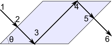
Линейно поляризованный свет (1) попадает в призму (2). Этот свет линейно поляризован под углом 45° к плоскости падения – то есть два перпендикулярных компонента электрического поля имеют равные величины и находятся в фазе. Призма описывается углом (θ), который при правильном подборе вызывает задержку по фазе на 45° между ортогональными компонентами электрического поля во время каждого полного внутреннего отражения (3 и 4). Затем свет выходит из призмы (5). Исходящий свет (6) теперь имеет круговую поляризацию. Взаимоперпендикулярные компоненты электрического поля по-прежнему имеют равные величины, но теперь они смещены по фазе на 90°.
Точное значение фазового сдвига, вызванного полным внутреннем отражением на поверхности без дополнительного покрытия, зависит от показателей преломления по обе стороны от поверхности, n1 и n2, и от угла падения, θ. Взаимосвязь между этими величинами и фазовой задержкой может быть выведена из закона Снеллиуса и уравнений Френеля. (Для получения более подробной информации о выводе уравнений вы можете ознакомиться с документацией к модели ромба Френеля.)
2 times textrm {atan} left(frac{costhetasqrt{sin^2theta – left(n_2/n_1right)^2}} {sintheta} right) = 45^ {circ}
В модели проводится два исследования. Сначала определяется значение θ, которое дает желаемую фазовую задержку в 45°. Затем этот угол используется для построения геометрии прибора и для трассировки оптических лучей в ней.
Исследование 1: Определение угла падения
На первом шаге вы можете использовать интерфейс Global ODEs and DAEs для решения приведенного выше уравнения и определения угла падения, который вызывает фазовую задержку δ = 45° между s– и p-поляризованными компонентами во время каждого полного внутреннего отражения при коэффициенте преломления n = 1/1.51. (Хотя указанное уравнение не является обыкновенным дифференциальным уравнением или дифференциально-алгебраическим уравнением, вы все равно можете использовать этот интерфейс для его решения.) Результирующее значение θ в этом примере равно 0.84855 радиана или ~48.618°.
Исследование 2: Трассировка оптического луча в системе
Затем, вы можете использовать интерфейс Geometrical Optics, чтобы проследить траекторию светового луча в ромбе Френеля, в т.ч. тогда, когда от претерпевает полное внутреннее отражение, падая под углом, вычисленным с помощью Global ODEs and DAEs. Обратите внимание, что в момент запуска луч обладает линейной поляризацией, причем направление его поляризации задано под углом 45° к плоскости падения.
Значение угла падения, полученное в первом исследовании (0.84855 радиана), может быть использовано для построения геометрии модели ромба Френеля, который представляет собой двумерный параллелограмм, экструдированный в 3D. Использование именно 3D-геометрии в расчёте предпочтительнее, поскольку это помогает проиллюстрировать состояние поляризации лучей, поскольку эллипсы поляризации могут отображаться только 3D графике Ray Trajectories. В этом случае параметры Стокса, которые вычисляются вдоль каждой траектории луча, используются для описания степени линейной или круговой поляризации луча.
Анализ полученных результатов
Теперь давайте подробнее рассмотрим полученные результаты на вышеупомянутом графике Ray Trajectories. На этом графике, показанном ниже, падающий луч входит с левой стороны призмы. Цвет иллюстрирует длину оптического пути вдоль луча, а круги и эллипсы вдоль пути луча показывают поляризацию. Стрелки по периметру каждого круга/эллипса показывают направление вращения вектора мгновенного поля.
По мере прохождения через ромб Френеля линейно поляризованный луч становится эллиптически поляризованным после первого полного внутреннего отражения. После двух отражения эллипсы поляризации сменяются кругами, что означает, что свет получает круговую поляризацию.
Распространение лучей в ромбе Френеля.
При таком ракурсе камеры может быть неочевидно, что исходящий свет имеет круглую поляризацию. Но, поворачивая 3D-график в графическом окне, вы можете увидеть, что поляризация света меняется с линейной на эллиптическую и, затем на круговую.
Анимация с поляризацией света в ромбе Френеля, падающий свет с линейной поляризацией (δ = 0), с эллиптической поляризацией после одного полного внутреннего отражения (δ = 45°) и с круговой поляризацией после двух отражений (δ = 90°).
Вы можете визуализировать поляризацию другим способом, построив график соотношения параметров Стокса, что показано ниже. В начале пути луч линейно поляризован, и соотношение равно нулю. После первого отражения отношение имеет значения с величиной от нуля до единицы, что указывает на различные степени эллиптической поляризации. Затем, после второго отражения, величина почти точно равна единице, становясь более согласованной с круговой поляризацией.
Соотношение четвертого и первого (третьего и нулевого) параметров Стокса, построенное как функция от длины оптического пути.
Дальнейшие шаги
Для самостоятельного тестирования модели ромба Френеля, представленной в данной статье нашего корпоративного блога, нажмите кнопку ниже. Вы попадете в Галерею моделей и приложений и сможете загрузить пошаговую документацию для этого примера и непосредственно MPH-файл.
Естественным развитием рассмотренной модели ромба Френеля является нанесение тонких диэлектрических покрытий на поверхности призмы. Диэлектрические покрытия влияют на коэффициенты Френеля на границе раздела; следовательно, они могут влиять на фазовую задержку между компонентами электрического поля в плоскости и вне плоскости. Примером такой модификации является тонкопленочный ахроматический фазовращатель на основе полного внутреннего отражения (TIRTF-APS). В нем используются тонкие пленки для компенсации частотной зависимости показателя преломления в стекле, так что исходящий свет сохраняет круговую поляризацию в широком диапазоне длин волн.
Дополнительные материалы
Хотите узнать больше о геометрической оптике? Обратите внимание на следующие материалы нашего блога:
- Как создавать сложные геометрии линз для задач геометрической оптики
- Моделирование интерферометра Саньяка и кольцевого лазерного гироскопа методами геометрической оптики
- Как проводить STOP-анализ оптических систем с помощью COMSOL Multiphysics®
Устройства,
служащие для преобразования естественного
света в линейно-поляризованный,
называется поляризаторами.
Устройства,
служащие для анализа степени поляризации
света называются
анализаторами.
Всякий анализатор можно условно
изобразить в виде решетки,
прутья
которой параллельны направлению
колебаний вектора
a
проходяшего сквозь неё света.
Если на анализатор падает естественный
свет,
то
его интенсивность не меняется, т.к в
естественном свете ни одно из направлений
плоскости
колебаний вектора
не является преобладающим. Очевидно:Ia=kaI0/2
, гдеka
— коэффициент прозрачности анализатора
для пропускаемого им линейно поляризованного
света.
Если падающий
свет частично поляризован, то Iaпри вращение анализатора будет меняться
в зависимости от ориентации его главной
плоскости по отношению к преимущественному
направлению колебаний векторав падающем свете.
Если на
анализатор падает линейно поляризованный
свет, полученный с помощью поляризатора,
и имеющий интенсивность Ip,то интенсивностьIa
света, прошедшего через анализатор
пропорциональнаIp
и зависит от угла между главными
плоскостями анализатора и поляризатора
и связаны законом Малюса:.
На практике
часто встречается необходимость выяснить
характер поляризации света. Рассмотрим
несколько наиболее типичных примеров.
-
Свет
плоскополяризованный. Такую поляризацию
можно обнаружить с помощью одного
поляризатора: при вращении его плоскости
пропускания вокруг направления пучка
интенсивность проходящего света будет
меняться, и при некотором положении
свет полностью гасится. -
Свет
естественный и поляризованный по кругу.
Чтобы их различить, одного поляризатора
недостаточно: в обоих случаях при
вращении его плоскости пропускания
вокруг направления пучка интенсивность
проходящего света не меняется. Если же
предварительно ввести пластинку
,
то поляризованный по кругу свет
превращается в плоскополяризованный,
поскольку эта пластинка вносит
дополнительную разность фаз.
Результирующая разность фаз окажется
равной нулю или,
и свет станет плоскополяризованным.
Его можно погасить поляризатором. Если
же свет естественный, то он останется
таковым и после прохождения пластинки.
Погасить этот свет не удастся, так как
при любом положении плоскости пропускания
поляризатора интенсивность прошедшего
света будет одинаковой. -
Свет
эллиптически- поляризованный и частично
–поляризованный. Для их различия
следует поместить в световом потоке
пластинку
,
а за ней поляризатор. Если вращением
пластинки вокруг направления пучка
найдется такое положение, при котором
свет, прошедший через нее, можно погасить,
вращая поляризатор, то свет эллиптически
поляризованный. Если это сделать не
удается, свет частично – поляризованный.
3.4.6. Интерференция поляризованных волн
Обыкновенная
и необыкновенная волны в основном
порождаются разными цугами, входящими
в состав естественного света. Поэтому
обыкновенная и необыкновенная волны ,
распространяющиеся в одноосном кристалле
и выходящие их него при падении
естественного света, некогерентны.
Однако обе волны можно сделать
когерентными, если на пути естественного
света установить поляризатор Рперед кристаллической пластинкой. При
этом плоскость пропускания должна
составлять с оптической осью кристалла
угол(обычно
).
В этом случае колебания каждого цуга
р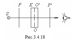
между обыкновеннойои необыкновеннойеволнами, и волныоиеоказываются когерентными.
Интерференция
не наблюдается, если складываемые волны
поляризованы во взаимно перпендикулярных
плоскостях. Чтобы изменить направление
поляризации, необходимо на пути вышедшего
из пластинки света поставить еще один
поляризатор. Он сведет два взаимно
ортогональных когерентных колебания
в одну плоскость и интерференция будет
обеспечена.
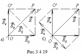
представлена схема наблюдения
интерференции поляризованных волн: S– обычный источник света,Р –
поляризатор,К– кристаллическая
одноосная пластинка,Р— второй поляризатор. Если в качестве
источника света взять лазер, то его
излучение является плоскополяризованным,
и необходимость поляризатораРотпадает. Картина интерференции будет
наиболее отчетливой, когда амплитуды
складываемых волн одинаковы. В этом
случае угол между плоскостью пропускания
поляризатораРи оптической осьюООдолжен
быть равен.
Рассмотрим
частные случаи: когда плоскости
пропускания обоих поляризаторов
параллельны друг другу ()
и взаимно перпендикулярны (),
в этом случае говорят, что поляризаторы
скрещены.
-
(рис.3.4.19,а).
Плоскополяризованная волна с амплитудойЕпосле поляризатораР разделяется
пластинкой на обыкновенную и необыкновенную
взаимно ортогональные волны с амплитудамии
.
Далее колебания этих волн приводятся
поляризаторомР
к одной плоскости с одинаковыми
амплитудамии
:
Результат
интерференции этих волн зависит от
разности фаз ,
которую они приобретут в пластинке. На
рис.3.4.20 показана фазовая (векторная)
диаграмма в предположении, что при
прохождении пластинки обыкновенная
волна отстает по фазе на.
По теореме косинусов имеем:
Интенсивность
прошедшего света
-
(рис.3.4.19,б). В
этом случае векторыи
направлены взаимно противоположно.
Поэтому кроме разности фаз,
вносимой пластинкой, необходимо добавить
еще, которая
обусловлена скрещенным расположением
поляризаторов. Разность фаз равна
+, и интенсивность
Таким образом,
интенсивности
и
оказываются «дополнительными»: в сумме
они дают интенсивность света, прошедшего
через поляризаторР.
Интенсивность
выходящего из поляризатора Р΄
света можно изменять, меняя разность
фаз. Этого можно
достичь, меняя либоλ(это приводит
к эффективному изменению окраски, т.е.
максимумы пропускания будут соответствовать
различным длинам волн), либо меняя
толщину пластинки. Последнее можно
сделать, поставив вместо пластинки
компенсатор. В таблице приведены условия,
при которых интенсивностии
достигают максимальных и минимальных
значений.
|
Разность хода Δ
Разность фаз
|
Соседние файлы в предмете [НЕСОРТИРОВАННОЕ]
- #
- #
- #
- #
- #
- #
- #
- #
- #
- #
- #


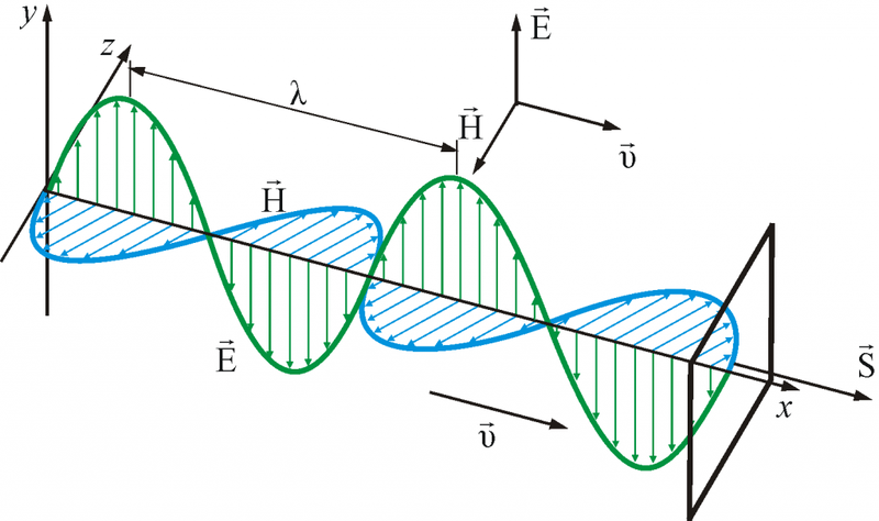
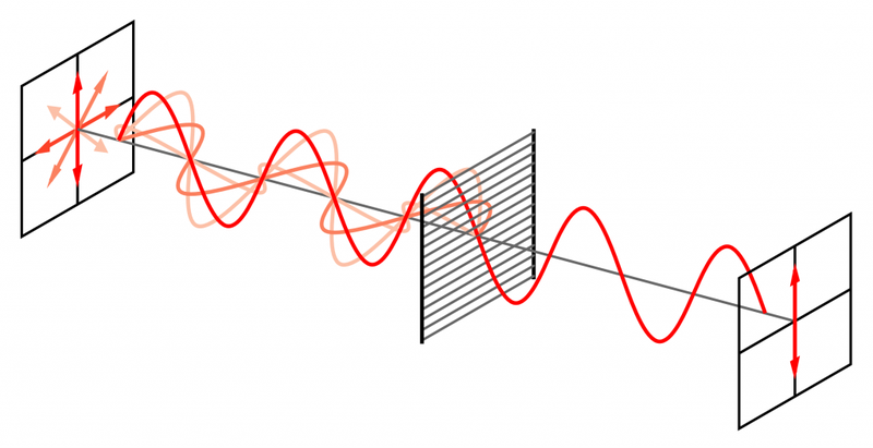
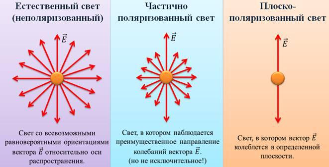
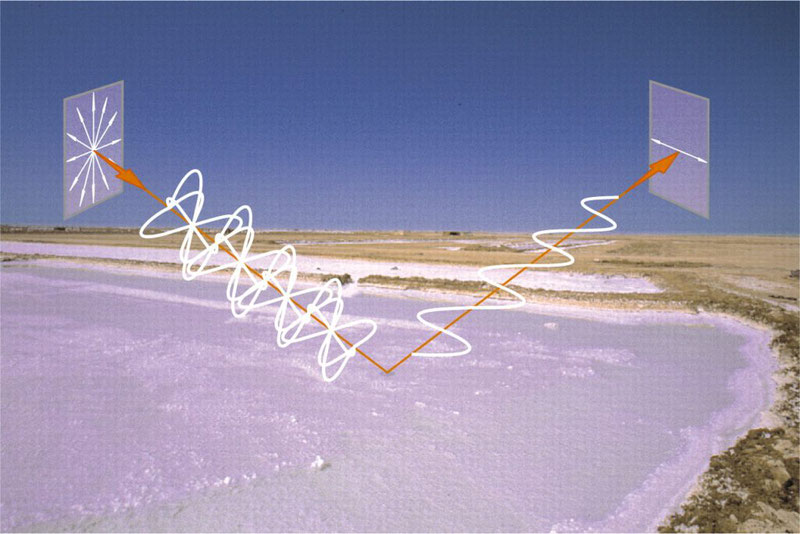
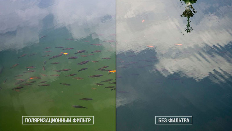

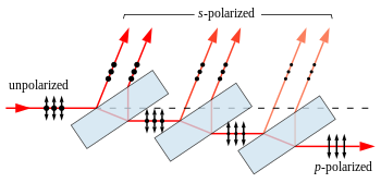


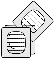


![I=I_{0}{frac {f}{f}}_{0}left[1+{frac {lambda (f_{0}-f)}{2c}}right]cos ^{2}theta _{i}](https://wikimedia.org/api/rest_v1/media/math/render/svg/086b8045ee17ec014ec0406a796dab2cb732f7fd)


