Многие 3D принтеры работают под управлением популярной прошивки Marlin. Прошивка изначально сконфигурирована для Ultimaker Original. Разберём основные настройки для других 3D принтеров.
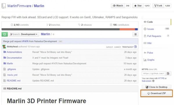
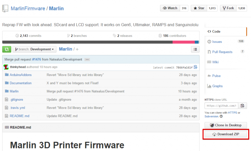
Прошивка лежит по этому адресу. Качаем. Давим на кнопку Download ZIP. Скачивается архив Marlin-Development.zip. Распаковываем его в выбранную папку.
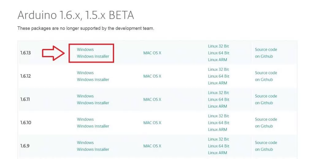
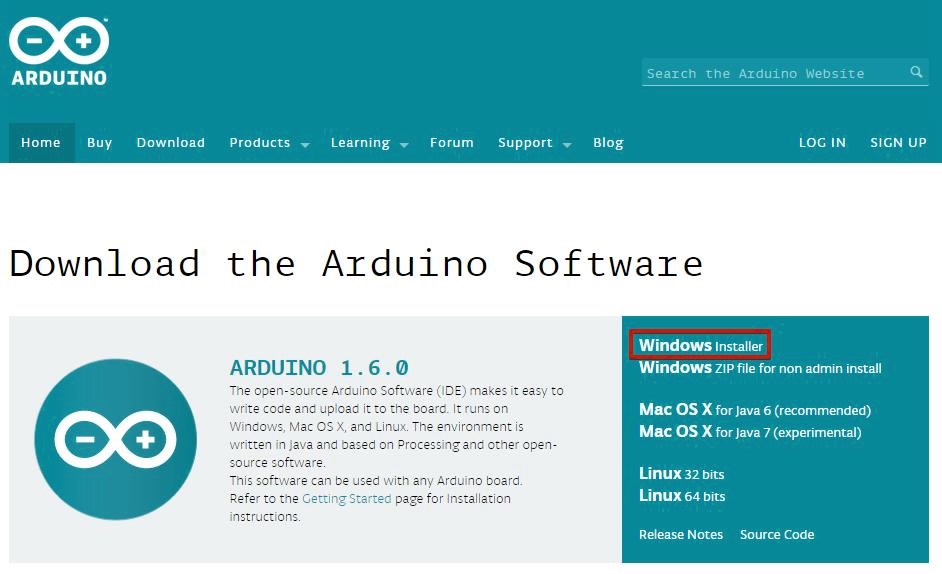
Теперь скачиваем Arduino IDE для исправления и загрузки прошивки в 3D принтер. Ссылка. Давим на Windows Installer. Скачивается установщик arduino-1.6.0-windows.exe. Запускаем его и устанавливаем среду Arduino IDE.

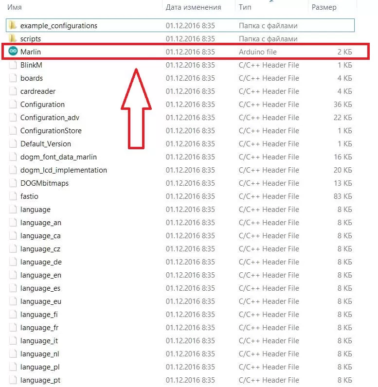
Переходим в папку с прошивкой и запускаем файл Marlin.ino.
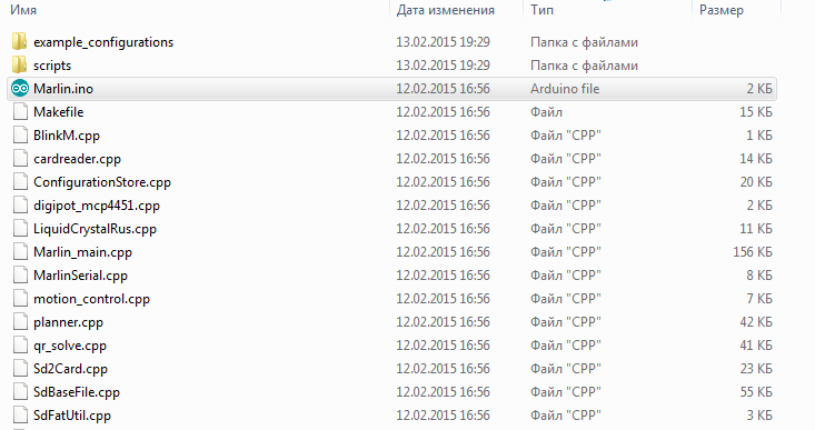
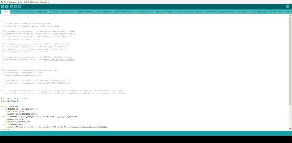
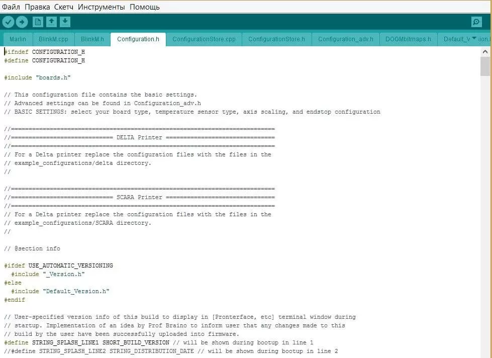
Открывается среда Arduino IDE с прошивкой. Нам нужна вкладка Configuration.h.
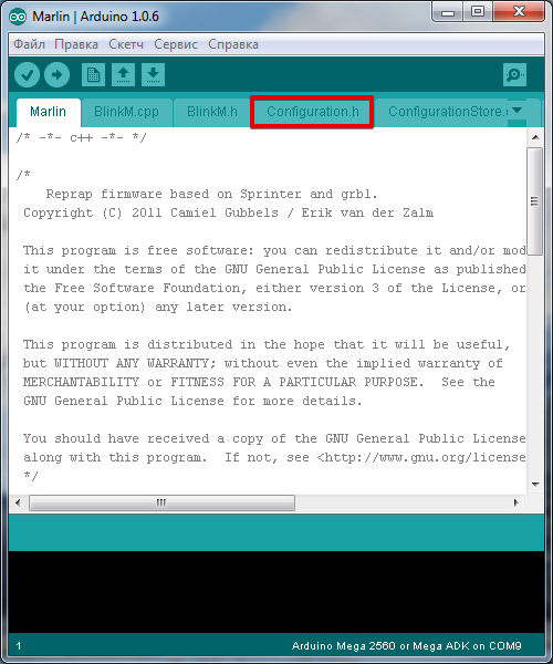
В начале мы видим ссылки на калибровку 3D принтера. Пролистываем дальше и читаем: ‘Это конфигурационный файл с основными настройками. Выберите тип контроллера, тип температурного датчика, откалибруйте перемещения по осям и сконфигурируйте концевые выключатели.’
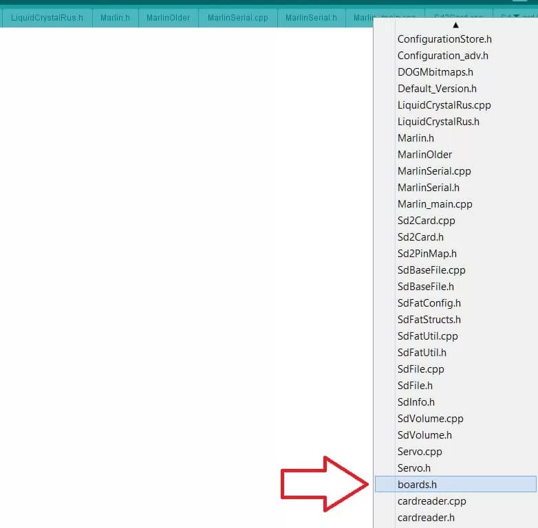
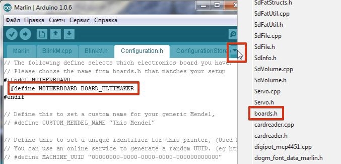
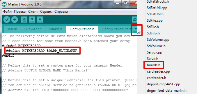
Начнём с выбора контроллера (MOTHERBOARD). Список контроллеров находится во вкладке boards.h. Давим на треугольник в правом верхнем углу и выбираем boards.h.
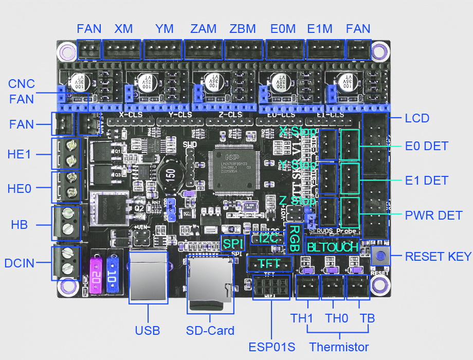
Теперь посмотрим на установленную электронику. Вот некоторые типы плат:
Melzi

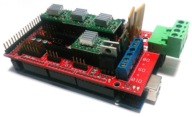
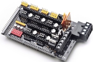
RAMPS 1.4
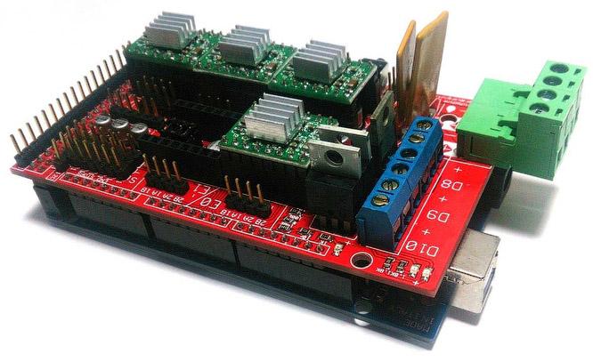
У меня стоит RAMPS 1.4.
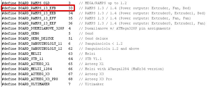
Заменяю в configuration.h ‘MOTHERBOARD BOARD_ULTIMAKER’ на ‘MOTHERBOARD BOARD_RAMPS_13_EFB’.
#ifndef MOTHERBOARD
#define MOTHERBOARD BOARD_RAMPS_13_EFB
#endif
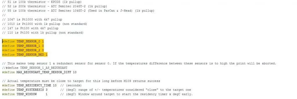
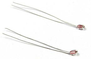
Следующим выбираем датчик температуры — термистор. Видим большой список ‘//// Temperature sensor settings:’. У меня стоит хотэнд E3D-v5 и китайский термистор на столе. Для E3D-v5 я выбираю ‘// 5 is 100K thermistor — ATC Semitec 104GT-2’, для стола ‘// 1 is 100k thermistor — best choice for EPCOS 100k’. Если тип термистора неизвестен можно выбрать 1, а если температура не понравится можно выбирать любой и тестировать. Меняю.
100K thermistor — ATC Semitec 104GT-2
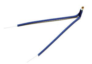
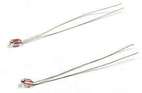
Обычный китайский термистор 100К

Ограничение максимальной температуры хотэнда ‘#define HEATER_0_MAXTEMP 275’.
Ограничение минимальной температуры хотэнда ‘#define EXTRUDE_MINTEMP 170’.
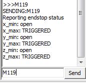
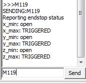
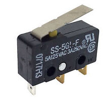
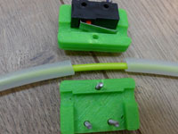
Если концевой выключатель подключен не стандартно и его состояние нужно инвертировать, то это можно сделать в прошивке, не перепаивая провода. Значения false или true. Команда M119 (например в Pronterface) показывает состояние концевых выключателей. У меня концевые выключатели стоят только в позиции HOME на MAX.
В положении HOME
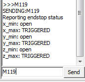
В положении отличном от HOME по всем осям
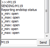
Мне ничего менять не потребовалось.
const bool X_MIN_ENDSTOP_INVERTING = true;
const bool Y_MIN_ENDSTOP_INVERTING = true;
const bool Z_MIN_ENDSTOP_INVERTING = true;
const bool X_MAX_ENDSTOP_INVERTING = true;
const bool Y_MAX_ENDSTOP_INVERTING = true;
const bool Z_MAX_ENDSTOP_INVERTING = true;
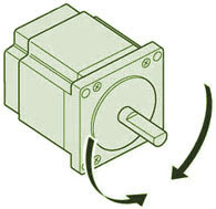
Изменение направления вращения шаговых двигателей, значения false или true. Правильные перемещения сопла относительно стола:
— По оси X — влево ‘-‘, вправо ‘+’.
— По Y — вперёд ‘+’, назад ‘-‘.
— По оси Z — сближение ‘-‘, удаление ‘+’.
— Экструдер. Extrude — выдавливание нити, Reverse (retract) — откат, втягивание нити.
#define INVERT_X_DIR false
#define INVERT_Y_DIR false
#define INVERT_Z_DIR false
#define INVERT_E0_DIR true
Дальше идёт настройка концевых выключателей. Нам нужно узнать где они расположены. Как это узнать? Начало координат находится в ближнем левом углу на поверхности стола, если сопло вывести в эту точку, то сработали бы концевики MIN, если в правую дальнюю верхнюю — сработают MAX. У меня в положении HOME находятся три концевых выключателя MAX, поэтому мои установки
// Sets direction of endstops when homing; 1=MAX, -1=MIN
#define X_HOME_DIR 1
#define Y_HOME_DIR 1
#define Z_HOME_DIR 1
Установка габаритов перемещения, после инициализации в положении HOME. Здесь мы задаём габариты рабочей зоны по X и Y, а также настройку сопла относительно стола.
Если при касании стола соплом срабатывает концевой выключатель (MIN), как у Ultimaker Original, то поднастройка сопла относительно стола выполняется перемещением концевого выключателя, а в ‘#define Z_MAX_POS’ записываем значение координаты при максимальном удалении сопла от стола. Координату можно узнать по команде М114 или посмотрев на экран дисплея.
Если концевой выключатель по Z срабатывает при максимальном удалении сопла от стола (MAX), то нужно найти габарит по Z самостоятельно. Устанавливаем значение ‘#define Z_MAX_POS’ изначально больше нормы, например 250 при габарите 200 мм. Опускаем сопло до касания стола и на дисплее (или по команде M114) видим координату больше нуля, теперь вычтем из установленного большого значения полученную координату и получим габарит по Z, который теперь запишем в ‘#define Z_MAX_POS’. По итогам печати первого слоя можно будет подкорректировать это значение.
// Travel limits after homing
#define X_MAX_POS 215
#define X_MIN_POS 0
#define Y_MAX_POS 215
#define Y_MIN_POS 0
#define Z_MAX_POS 200
#define Z_MIN_POS 0
Можно подкорректировать скорость перемещения в положение HOME.
#define HOMING_FEEDRATE {50*60, 50*60, 4*60, 0} // set the homing speeds (mm/min)
Переходим к самому важному. Настройка шагов перемещения по осям. Экструдер тоже ось. Мои настройки.

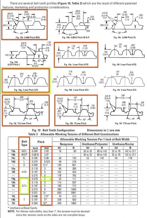
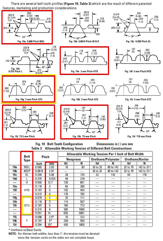
Теперь посмотрим, как я их получил. По всем осям стоят шаговые двигатели 200 шагов на оборот, 16 микрошагов на шаг (устанавливается перемычками на плате). По осям X и Y стоит приводной ремень GT2 с шагом 2 мм и 20-ти зубые шкивы, итого получаем формулу (200*16)/(2.0*20). По оси Z стоят шпильки М8 с шагом резьбы 1,25 мм, итого формула 200*16/1.25.
Находим спецификации (даташит) на установленные шаговые двигатели. Видим, что за один шаг вал поворачивается на 1,8 градуса, а это значит 360/1,8=200 шагов на полный оборот. Этот параметр одинаковый у большинства шаговых двигателей устанавливаемых в домашние 3D принтеры.

Профили ремней, обычно используемых на 3D принтерах и их шаг. Оригинал здесь, страница 61.
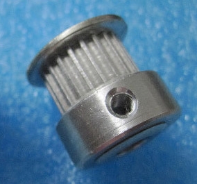
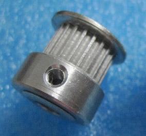
Шкив
Как померить шаг винта? Замеряем участок винта и считаем на нём витки, затем длину участка в миллиметрах делим на количество витков 20/16=1.25 мм. Для более точного результата замеряем участок максимальной длины.
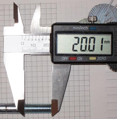
Настройка экструдера зависит от коэффициента редукции и диаметра подающей шестерни. Подберём экспериментально, после первой заливки прошивки в 3D принтер. Откручиваем сопло и уменьшаем ограничения минимальной температуры сопла до 5 градусов ‘#define EXTRUDE_MINTEMP 5’. Теперь экструдер будет работать при холодном сопле, что нам и нужно. Пока не меняем настройки экструдера. Для настройки я использую программу Pronterface. Для начала ставим 50 мм и скорость 100 мм/сек. 50 мм — это длина прутка, проходящего через экструдер. Измеряем длину прутка прошедшего через экструдер линейкой или штангенциркулем.

Подбирая настройку экструдера добиваемся точной цифры на разумной длине прутка, например 300 мм. После настройки вернём ограничения минимальной температуры ‘#define EXTRUDE_MINTEMP 170’.
Следующие цифры — это ограничение максимальной скорости перемещения по осям. На X и Y я ставлю 200 мм, остальные не трогаю.
#define DEFAULT_MAX_FEEDRATE {200, 200, 5, 25}
Настройка ускорения перемещений по осям. При больших ускорениях возможны пропуски шагов. Можно подбирать, гоняя в программе Pronterface по осям на заданной скорости. Вот мои настройки:
#define DEFAULT_MAX_ACCELERATION {1000,1000,100,10000}
#define DEFAULT_ACCELERATION 1500
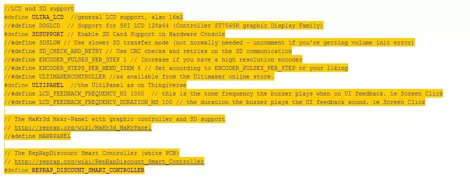
Осталось активировать LCD дисплей с SD картой. Свой дисплей я нашёл на RepRap.org и идентифицировал как RepRapDiscount Smart Controller.
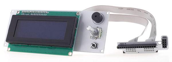
Раскомментируем (уберём двойные слэши) следующие строки:
#define ULTRA_LCD
#define SDSUPPORT
#define ULTIPANEL
#define REPRAP_DISCOUNT_SMART_CONTROLLER
Есть ещё один твик для повышения точности срабатывания некоторых концевых выключателей. При настройке нуля по Z столкнулся с тем, что после каждой инициализации HOME положение сопла над столом немного менялось. Порывшись в прошивке нашёл параметр отвечающий за инициализацию концевых выключателей. Переходим во вкладку Configuration_adv.h и ищем строку ‘#define Z_HOME_RETRACT_MM 2’, меняем значение 2 на 5 и больше не вспоминаем про этот параметр.
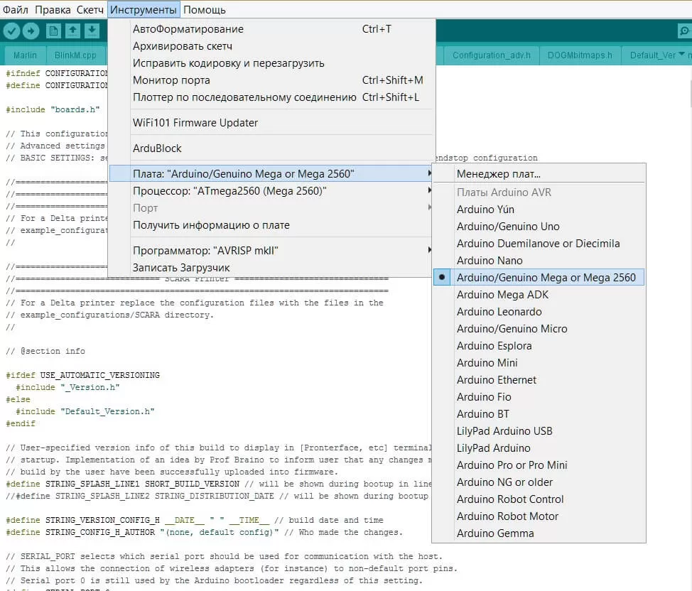
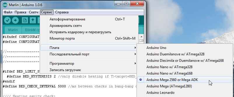
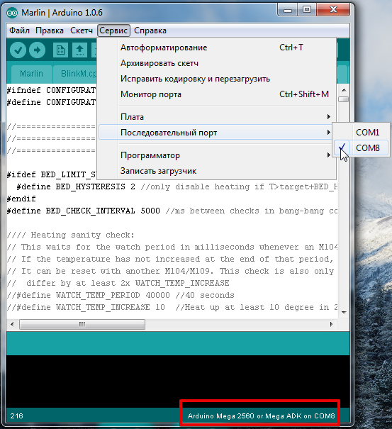
Пора заливать прошивку в контроллер. Для этого нужно в Arduino IDE правильно выставить тип платы и номер COM порта. Внизу окна отобразится тип платы и номер порта. Не забываем сохранять изменения (Ctrl+S).
RAMPS
MELZI
Для выбора нужной платы в Arduino IDE нужно скопировать с заменой всё из папки с прошивкой ‘Marlin-DevelopmentArduinoAddonsArduino_1.5.xhardwaremarlinavr’ в папку Arduino IDE ‘C:Program Files (x86)Arduinohardwarearduinoavr’. После этого появляется возможность выбрать плату Sanguino (базовая плата для Melzi) и нужный тип процессора. У меня нет платы Melzi, поэтому проверить не могу.
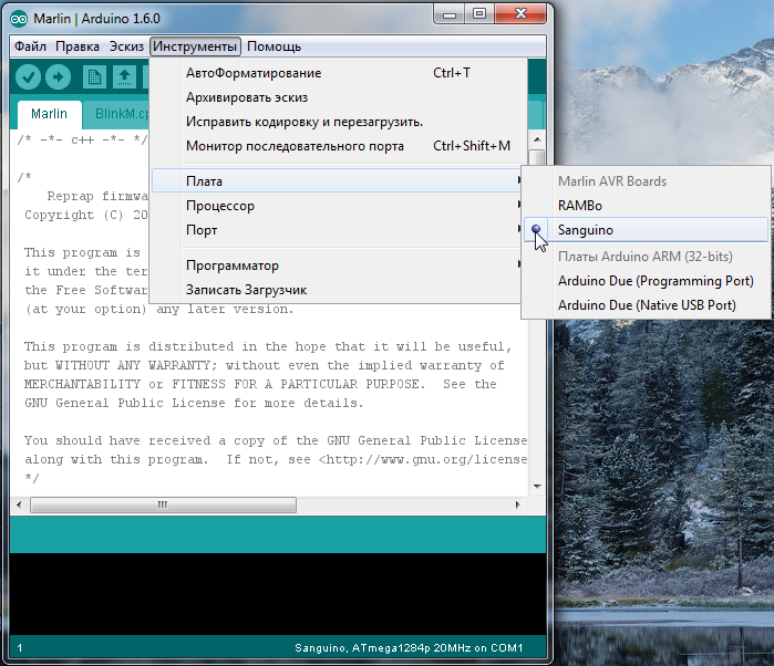
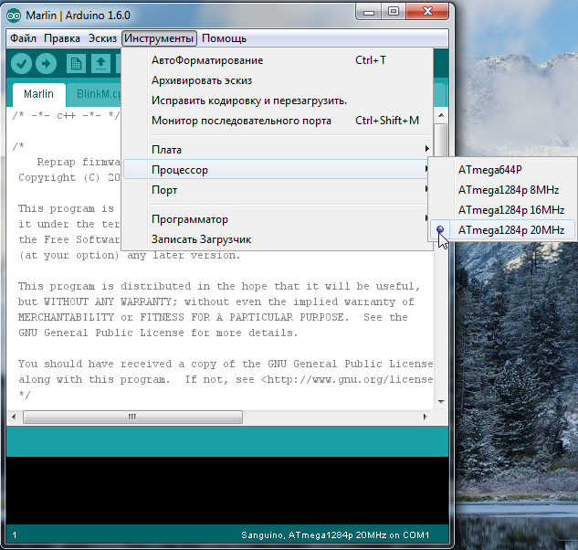
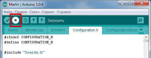
Для заливки прошивки нажимаем на круг со стрелкой.
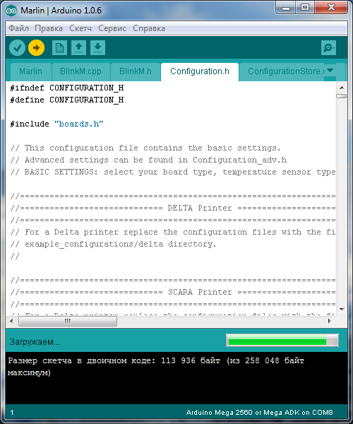
Прогресс заливки прошивки отображается индикатором
После того, как всё заработает нужно откалибровать PID нагрева хотэнда и стола. Для этого я использую Pronterface. Вводим команду ‘M303 E0 C8 S260‘. Где M303 — команда калибровки, E0 — хотэнд, C8 — количество циклов нагрева-охлаждения, S260 — типичная температура работы сопла.
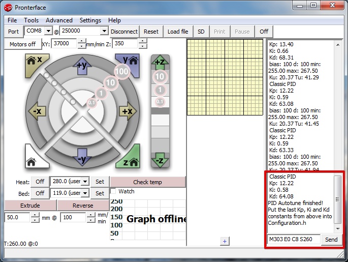
Последние результаты записываем в прошивку.
#define DEFAULT_Kp 12.22
#define DEFAULT_Ki 0.58
#define DEFAULT_Kd 64.08
По такой же схеме калибруем PID стола. Команда ‘M303 E-1 C8 S110‘. Где E-1 — стол, S110 — типичная температура нагрева стола. Последние результаты записываем в прошивку. У меня стол нагревается очень медленно и поэтому приходится перезапускать команду из-за ошибки Timeout.
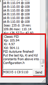
#define DEFAULT_bedKp 105.94
#define DEFAULT_bedKi 4.97
#define DEFAULT_bedKd 564.11
Как узнать уже прошитые в 3D принтер параметры чтобы не калибровать повторно?
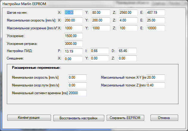
Параметры установленные в прошивке можно узнать в программе Repetier-Host через меню КонфигурацияКонфигурация EEPROM. Предварительно нужно указать COM порт в настройках и нажать кнопку ‘Подсоединить‘.
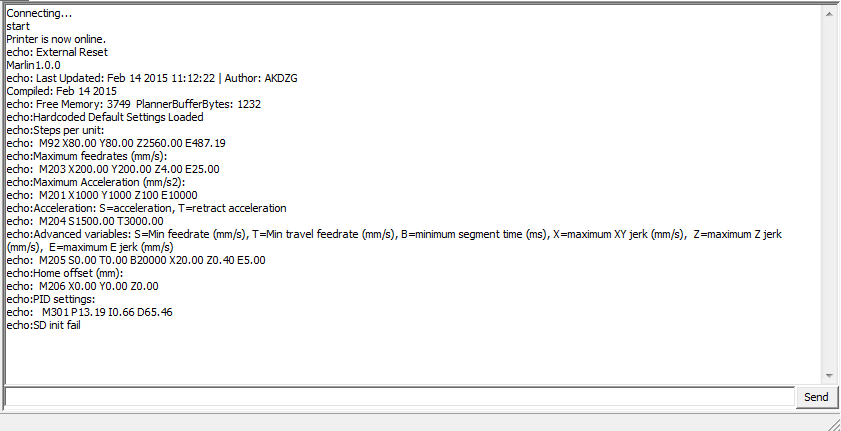
При подключении 3D принтера к программе Pronterface в правой части окна выводится список параметров прошивки
Также параметры можно увидеть на LCD дисплее. Через меню ControlMotion.
Хотелось бы увидеть подобные инструкции для Delta принтеров, CoreXY и H-Bot 3D принтеров.
Критические замечания настоятельно приветствуются, так как впоследствии инструкция будет размещена в 3D-Вики. Также очень важно мнение новичков, так как всё это делается именно для Вас!
Перед началом работы с непрофессиональным или полу профессиональным 3D принтером, а также Kit-набором для самостоятельной сборки часто необходимо «залить» и настроить прошивку. Прошивка представляет собой программный код, основными задачами которого являются: считывание и воспроизведение G-code, управление принтером через различные интерфейсы, вывод информации о процессе печати. Другими словами, прошивка необходима, чтобы железо и набор электроники «ожили» и можно было ими управлять. Заливается прошивка на плату управления. У разных 3D принтеров различные платы управления, соответственно, прошивки тоже разные.
В наших 3D принтерах Prusa i3 Steel используется связка плат Arduino Mega 2560 и Ramps 1.4, поэтому в данной статье мы подробно рассмотрим и разберем настройки подходящей для них прошивки, Marlin.
Если вы еще не собрали электронику, то ознакомьтесь со статьей: Подключение Ramps 1.4 к 3D принтеру
Данная прошивка является одной из самых популярных, в том числе, потому что разработчики регулярно добавляют в нее новые возможности: автоматическая регулировка зазора, датчик окончания прутка и многое другое. Кроме того, эта прошивка абсолютно бесплатная, и ее можно скачать с официального сайта.
Где взять?
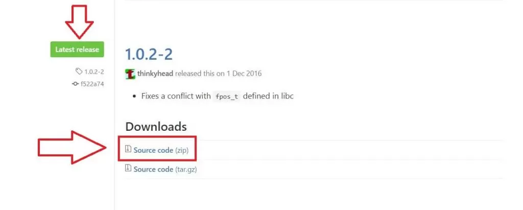
Последняя версия прошивки Marlin выложена на официальном сайте разработчика https://github.com/MarlinFirmware/Marlin. Скачать более ранее версии прошивки можно по ссылке. Также на сайте присутствуют много различных версий, но мы рекомендуем скачивать самую последнюю версию, помеченную как Latest release. На момент написания статьи, данной версией была 1.0.2-2
Под Downdloads нажмите на Source code (zip) и скачайте архив прошивки себе на компьютер. Далее извлеките содержимое архива в папку.
Установка Arduino IDE
После того, как вы скачали прошивку, нужно ее отредактировать и в дальнейшем записать на микроконтроллер платы управления (Arduino mega 2560 ). Для этих целей понадобиться программа Arduino IDE, скачать которую можно бесплатно с официального сайта Arduino.
Обратите внимание! Данная программа Arduino IDE регулярно обновляется и возможен такой вариант, что при заливки прошивки на плату, с новыми версиями Arduino IDE могут возникнуть проблемы, а именно будут вылазить ошибки, и вы не сможете записать прошивку в микроконтроллер. Поэтому, при возникновении проблем, попробуйте скачать более старую версию программы, например версию 1.6.0 )
Для надежности можете сразу скачать проверенную версию 1.6.0
Нажмите на Windows Installer, и вас перекинут на другую страницу, где необходимо нажать на кнопку JUST DOWNLOAD, далее начнется скачивание файла. Установите программу и приступите к следующему шагу.
Редактирование прошивки Marlin
Вы скачали непосредственно саму прошивку Marlin и программу Arduino IDE, с помощью которой можно редактировать. Откройте папку с прошивкой «Marlin», найдите файл «Marlin» с расширением .ino
Откройте этот файл, откроется программа Arduino IDE
Вверху окна программы находиться много вкладок, в каждой из которых располагаются куски кода, от которых и зависит работа 3D принтера. Вам потребуется только несколько основных вкладок. Первая и основная вкладка это «Configuration.h»
Этот конфигурационный файл, который содержит основные настройки. Именно в этой вкладке необходимо произвести основные изменения.
Обратите внимание! Все изменения в прошивке проведите по порядку сверху вниз. Эти изменения затронут основные участки кода, и они необходимы для начального запуска вашего 3D принтера.
Устанавливаем необходимую скорость в бодах
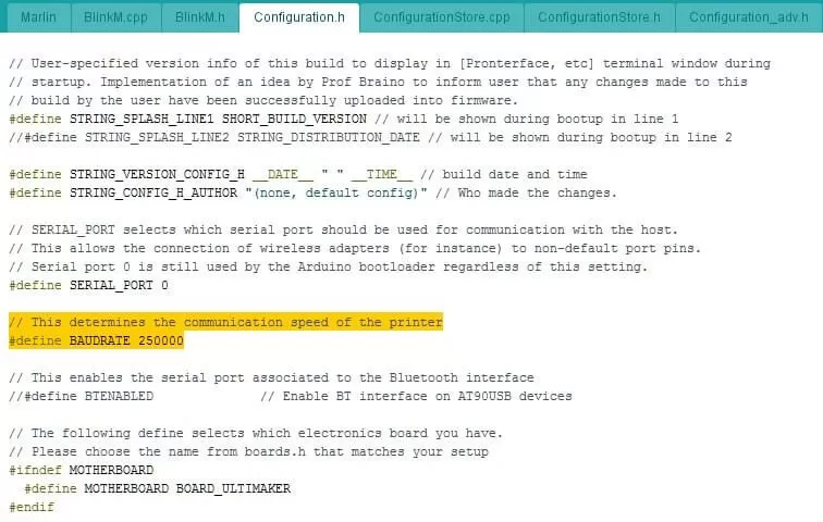
Первое, что необходимо поменять — скорость в бодах. По умолчанию скорость стоит 250000 ( 47 строчка кода)
// This determines the communication speed of the printer #define BAUDRATE 250000
Для каждой платы производитель рекомендует свои скорости, поэтому для связки Arduino mega 2560 и Ramps 1.4 необходимо поставить 115200, то есть участок кода у нас должен принять следующий вид:
// This determines the communication speed of the printer #define BAUDRATE 115200
Если вы используете плату Gen V1.4, то скорость должна быть 250000.
Выбираем управляющую плату
После установки скорости в бодах, необходимо указать используемую плату управления ( 55 строчка кода).
#ifndef MOTHERBOARD #define MOTHERBOARD BOARD_ULTIMAKER #endif
По умолчанию стоит плата 3D принтера Ultimaker — BOARD_ULTIMAKER, поэтому необходимо поменять плату. Весь список плат находится во вкладке «BOARDS_H»
Там предоставлен огромный список различных плат, но вам необходимы только следующие:
#define BOARD_RAMPS_13_EFB 33 // RAMPS 1.3 / 1.4 (Power outputs: Extruder, Fan, Bed)
#define BOARD_RAMPS_13_EEB 34 // RAMPS 1.3 / 1.4 (Power outputs: Extruder0, Extruder1, Bed)
#define BOARD_RAMPS_13_EFF 35 // RAMPS 1.3 / 1.4 (Power outputs: Extruder, Fan, Fan)
#define BOARD_RAMPS_13_EEF 36 // RAMPS 1.3 / 1.4 (Power outputs: Extruder0, Extruder1, Fan)
Эти платы относятся к Arduino mega 2560 и Ramps 1.4. В зависимости от модификации вашего 3D принтера, необходимо выбрать соответствующую плату. Например, стандартная связка 1 экструдер + обдув рабочей области + нагревательный стол соответствует плате BOARD_RAMPS_13_EFB
Название платы необходимо скопировать и заменить на вкладке «Configuration.h», меняем следующие строчки:
Меняем название 3D принтера
При настройке обязательно придумайте название своему 3D принтеру и укажите это в прошивке. Зачем? Название принтера отображается на его LCD дисплее, такая возможность точно предусмотрена на таком дисплее.
Найдите строчки: (59 строчка)
// #define CUSTOM_MENDEL_NAME "This Mendel"
Перед #define стоят «//» — это означает, что данные строчки не используются в коде, а служат в качестве пояснений. Чтобы активировать данную строчку, необходимо раскомментировать строку, уберите // перед строчкой.
Измените название по умолчанию «This Mendel» на ваше название 3D принтера, например, «P3Steel». Получаем следующие:
Выбираем датчик температуры стола и экструдера
Выше были указаны настройки прошивки для 1 экструдера и нагревательного стола, то есть в 3D принтере присутствуют два нагревательных элемента, температуры которых необходимо регулировать. Контроль температуры производится с помощью датчиков температуры — термисторов.
Существует большое количество различных термисторов с различными характеристиками, поэтому в прошивке необходимо указать какой именно термистор стоит у вас. Это нужно, чтобы в дальнейшем принтер показывал верную температуру. В прошивке найдите список поддерживаемых термисторов:
//// Temperature sensor settings: // -2 is thermocouple with MAX6675 (only for sensor 0) // -1 is thermocouple with AD595 // 0 is not used // 1 is 100k thermistor - best choice for EPCOS 100k (4.7k pullup) // 2 is 200k thermistor - ATC Semitec 204GT-2 (4.7k pullup) // 3 is Mendel-parts thermistor (4.7k pullup) // 4 is 10k thermistor !! do not use it for a hotend. It gives bad resolution at high temp. !! // 5 is 100K thermistor - ATC Semitec 104GT-2 (Used in ParCan & J-Head) (4.7k pullup) // 6 is 100k EPCOS - Not as accurate as table 1 (created using a fluke thermocouple) (4.7k pullup) // 7 is 100k Honeywell thermistor 135-104LAG-J01 (4.7k pullup) // 71 is 100k Honeywell thermistor 135-104LAF-J01 (4.7k pullup) // 8 is 100k 0603 SMD Vishay NTCS0603E3104FXT (4.7k pullup) // 9 is 100k GE Sensing AL03006-58.2K-97-G1 (4.7k pullup) // 10 is 100k RS thermistor 198-961 (4.7k pullup) // 11 is 100k beta 3950 1% thermistor (4.7k pullup) // 12 is 100k 0603 SMD Vishay NTCS0603E3104FXT (4.7k pullup) (calibrated for Makibox hot bed) // 13 is 100k Hisens 3950 1% up to 300°C for hotend "Simple ONE " & "Hotend "All In ONE" // 20 is the PT100 circuit found in the Ultimainboard V2.x // 60 is 100k Maker's Tool Works Kapton Bed Thermistor beta=3950 // // 1k ohm pullup tables - This is not normal, you would have to have changed out your 4.7k for 1k // (but gives greater accuracy and more stable PID) // 51 is 100k thermistor - EPCOS (1k pullup) // 52 is 200k thermistor - ATC Semitec 204GT-2 (1k pullup) // 55 is 100k thermistor - ATC Semitec 104GT-2 (Used in ParCan & J-Head) (1k pullup) // // 1047 is Pt1000 with 4k7 pullup // 1010 is Pt1000 with 1k pullup (non standard) // 147 is Pt100 with 4k7 pullup // 110 is Pt100 with 1k pullup (non standard)
В списке найдите свой, запомните цифру слева. Как правило, многие используют китайский термистор 100 кОм, для него подходит термистор под номером «1».
// 1 is 100k thermistor - best choice for EPCOS 100k (4.7k pullup)
Внесите изменения в нужном месте (строчки 115-118)
#define TEMP_SENSOR_0 -1 #define TEMP_SENSOR_1 -1 #define TEMP_SENSOR_2 0 #define TEMP_SENSOR_BED 0
По умолчанию в прошивке активированы два первых термистора:
TEMP_SENSOR_0 — отвечает за термистор первого экструдера
TEMP_SENSOR_1 — отвечает за термистор второго экструдера
TEMP_SENSOR_BED — отвечает за термистор стола
Поменяйте строчки и получите следующее:
TEMP_SENSOR_1 и TEMP_SENSOR_2 не используются, поэтому напротив них ставим «0» нули.
Ограничение максимальной температуры
Для ограничения максимальной температуры необходимы следующие строчки (140-143)
#define HEATER_0_MAXTEMP 275 #define HEATER_1_MAXTEMP 275 #define HEATER_2_MAXTEMP 275 #define BED_MAXTEMP 150
Числа стоящие справа, а именно 275 и 150 — это максимальные температуры экструдера и нагревательного стола соответственно.
Когда температура превышает максимальный Temp, ваш нагреватель будет выключен. Эта функция существует для того, чтобы защитить ваш экструдер от случайного перегрева. Если вы используете хотенд с тефлоном внутри, то рекомендуем ограничить температурой 260 градусов.
Ограничение минимальной температуры
Также в прошивке по умолчанию стоит ограничение минимальной температуры экструдера в 170 градусов. Это означает что, если температура экструдера будет ниже 170 градусов, то двигатель экструдера не будет вращаться и пластик не будет подаваться. Защита от проталкивания не прогретого пластика (строчка 230).
#define EXTRUDE_MINTEMP 170
Если хотите отключить данную функцию, то перед строчкой поставьте «//»
Настройка концевых выключателей
Настройка логики работы концевиков
В первую очередь на что нужно обратить внимание — это какие концевики вы используете и какой у них принцип работы. В прошивке необходимо правильно указать логику работы концевиков. Найдите следующие строчки (301-306)
const bool X_MIN_ENDSTOP_INVERTING = true; // set to true to invert the logic of the endstop. const bool Y_MIN_ENDSTOP_INVERTING = true; // set to true to invert the logic of the endstop. const bool Z_MIN_ENDSTOP_INVERTING = true; // set to true to invert the logic of the endstop. const bool X_MAX_ENDSTOP_INVERTING = true; // set to true to invert the logic of the endstop. const bool Y_MAX_ENDSTOP_INVERTING = true; // set to true to invert the logic of the endstop. const bool Z_MAX_ENDSTOP_INVERTING = true; // set to true to invert the logic of the endstop.
Если у вас механические концевики, то при срабатывание цепь замыкается, напротив каждой строчки соответствующей оси поставьте значения «true». Если вы используете оптические концевики, то при срабатывании цепь размыкается, напротив каждой строчки соответствующей оси поставьте значения «false».
По умолчанию в прошивке напротив каждого концевика стоят значения «true», что соответствуют механическим концевикам.
После настройки работу концевиков можно проверить командой M119 в консоли.
В ответ должен прийти текст:
x_min: open – концевик не сработал;
x_min: TRIGGERED – концевик сработал.
Установка положения «HOME» — дом
В прошивке поддерживаются 3 пары концевиков: для каждой оси X, Y и Z по два концевика min и max. Как правило, ставятся концевики только для минимального положения каждой оси, а максимальное задается в прошивке.
Положение дом (начальное положение), будет находиться в минимальных положениях концевиков и это задается в прошивке: (строчки 337-339)
#define X_HOME_DIR -1 #define Y_HOME_DIR -1 #define Z_HOME_DIR -1
1=MAX, -1=MIN
Изменения направления вращения двигателей
При сборке 3D принтера, а именно при подключение шаговых двигателей к плате, возможна такая ситуация: когда вы все настроили и подключили, при нажатии «home» (дом), каретка одной из осей едет в другую сторону (не к концевику), тогда необходимо перевернуть коннектор шагового двигателя на 180 градусов или поменять значения в прошивке:
#define INVERT_X_DIR true // for Mendel set to false, for Orca set to true #define INVERT_Y_DIR false // for Mendel set to true, for Orca set to false #define INVERT_Z_DIR true // for Mendel set to false, for Orca set to true #define INVERT_E0_DIR false // for direct drive extruder v9 set to true, for geared extruder set to false #define INVERT_E1_DIR false // for direct drive extruder v9 set to true, for geared extruder set to false #define INVERT_E2_DIR false // for direct drive extruder v9 set to true, for geared extruder set to false
Например, если у вас каретка оси Y в другую сторону, то необходимо найти строчку
#define INVERT_Y_DIR false // for Mendel set to true, for Orca set to false
и поменять «false» на «true». И так с каждой осью и экструдером.
Установка габаритов перемещения
Чтобы 3D принтер определял рабочую область, необходимо указать ее размеры в прошивке: (строчки 345-350)
#define X_MAX_POS 205 #define X_MIN_POS 0 #define Y_MAX_POS 205 #define Y_MIN_POS 0 #define Z_MAX_POS 200 #define Z_MIN_POS 0
Напротив каждой строчки укажите соответствующие габариты, по умолчанию рабочая область задана 205x205x200 мм
Настройка шагов перемещения по осям
Указание количества шагов шаговых двигателей — одна из главных настроек прошивки (строчка 490):
#define DEFAULT_AXIS_STEPS_PER_UNIT {78.7402,78.7402,200.0*8/3,760*1.1} // default steps per unit for Ultimaker
В скобках через запятую для каждой оси указывается количество шагов, который должен сделать шаговый двигатель, чтобы каретка проехала 1 мм. Откуда взять данные значения? Можно рассчитать или возьмите уже известные.
Расчет осей X и Y (ремни)
По всем осям стоят шаговые двигатели 200 шагов на оборот, 16 микро-шагов на шаг (это устанавливается перемычками на плате).
По осям X и Y стоит приводной ремень GT2 с шагом 2 мм и шкивы с 20 зубьями.
Получается:
(200*16)/(2.0*20)=80
Столько шагов должен сделать шаговый двигатель, чтобы ось X и Y проехала ровно 1 мм.
Если у вас зубчатый шкив Gt2 с шагом 2 мм и с количеством зубьев 20, то формула такая:
(200*16)/(2.0*16)=100
Расчет оси Z (ходовой винт)
По оси Z могут стоять:
- Шпилька М8 с шагом резьбы 1,25 мм, тогда формула: 200*16/1.25=2560
- Шпилька M5 с шагом резьбы 0.8 мм, тогда формула: 200*16/0.8=4000
- Трапецеидальный винт диаметром 8 мм с шагом 1 мм и заходностью 1, тогда формула: 200*16/1=3200
- Трапецеидальный винт диаметром 8 мм с шагом 2 мм и заходностью 1, тогда формула: 200*16/2=1600
- Трапецеидальный винт диаметром 8 мм с шагом 2 мм и заходностью 4, тогда формула: 200*16/2*4=400
В Pruse i3 Steel используются шпильки М5 , тогда получается число 4000.
Расчет экструдера
Настройка подачи экструдера зависит от коэффициента редукции и диаметра подающей шестерни. Количество шагов, который должен сделать шаговый двигатель экструдера, чтобы продавить пластик на 1 мм подбирается экспериментально после первой заливки прошивки в 3D принтер.
Открутите сопло и уменьшите ограничение минимальной температуры сопла до 5 градусов:
#define EXTRUDE_MINTEMP 5
Теперь экструдер будет работать при холодном сопле. Не меняя настроек экструдера, нажмите прогнать пластик на 100 мм. Измерьте длину прутка прошедшего через экструдер линейкой или штангенциркулем.
Подбирая настройку экструдера добейтесь точной цифры на разумной длине прутка, например 200 мм. После настройки верните ограничения минимальной температуры:
#define EXTRUDE_MINTEMP 170
Ограничение максимальной скорости перемещения по осям
#define DEFAULT_MAX_FEEDRATE {500, 500, 5, 25} // (mm/sec)
По умолчанию стоят скорости 500,500,5, 25 мм/c на оси X,Y,Z и экструдер соответственно. Рекомендуем понизить скорость с 500 до 200.
Настройка ускорения перемещений по осям
Еще одной из важных настроек является задание ускорений для различных осей, так как из-за некорректной настройки этого момента часто бывают проблемы при печати, а именно смещение слоев по причине пропуска шагов двигателя. Если поставить слишком большие ускорения, то будут пропуски. По умолчанию в прошивке стоят следующие значения:
#define DEFAULT_MAX_ACCELERATION {9000,9000,100,10000} // X, Y, Z, E maximum start speed for accelerated moves. E default values are good for Skeinforge 40+, for older versions raise them a lot. #define DEFAULT_ACCELERATION 3000 // X, Y, Z and E max acceleration in mm/s^2 for printing moves #define DEFAULT_RETRACT_ACCELERATION 3000 // X, Y, Z and E max acceleration in mm/s^2 for retracts
Для осей X и Y стоят ускорения 9000 мм/c^2 — это очень много.
Для первичной настройки установите не более 1000 и для DEFAULT_ACCELERATION поставьте 1500, вместо 3000.
Активация дисплея
Последние, что остается сделать — это активировать нужный вам дисплей. Один из самых популярных дисплеев, это RepRapDiscount Smart Controller. Найдите и раскомментируйте следующие строчки:
#define ULTRA_LCD #define SDSUPPORT #define ULTIPANEL #define REPRAP_DISCOUNT_SMART_CONTROLLER
Перед этими строчками, не должны стоять «//». Должно получиться следующее:
Заливка прошивки
После всех основных изменений прошивки, можно ее заливать. В программе Arduino IDE зайдите во вкладку «Инструменты» -> «Плата» и выберите «Arduino/Genuino Mega or Mega 2560»
И там же нужно выставить верный COM порт вашего 3D принтера. Для заливки прошивки нажимаем на круг со стрелкой.
Прогресс заливки прошивки отображается индикатором, а после успешного завершения на экране появятся подтверждающие сообщение.
Дальше можете пробовать запускать ваш 3D принтер. Удачи!
Step 0: extracting old settings & setting up
The first step is to get yourself a printing software that has a Console or Terminal like present in Repetier Host, Pronterface (as part of the Printrun software suite), OctoPrint or any other tool (e.g. serial connection with PuTTY also works) that allows to communicate with the printer to extract the settings we already have. Once we have the software installed and the printer connected, send M503 and copy the old settings into a file for later use.
Next, we need our development surroundings. Usually, you want to use Arduino IDE (but the PlatformIO plugin as part of Visual Studio Code can be used for both Arduino based microprocessors as 32-bit processors), but you need to know what kind of board the control board of your printer is derived from because some boards have native IDEs that work better for them.
Step 1: Choice of Firmware
By some metrics of early 2020, about 80 % of all shipped machines run Marlin in some fashionneed citation. The most prolific versions of Marlin at that point are often cited to be 1.1.9 and 2.x. Since anything before 1.1.9 is very much obsolete and needs an update anyway, we will look into 1.1.9 and 2.x only. Version 2.x was developed to include 32-bit microprocessors, but is compatible with 8-bit microprocessor printer boards. As the version jump indicates though, 2.x is pretty much an entire rewrite, so do your choice and jump to the correct next step.
Marlin 1.1.x
Typically, you start by grabbing a blank Marlin 1.1.9. The next step is to alter the static settings of the printer to match yours in Configuration.h — best use the settings from what we pulled earlier via M503 as a start. Alternatively, you can search for a configuration of your printer between known configuration files. You should at least need to adjust these:
For communications and filament diameter:
#define BAUDRATE 250000

// Generally expected filament diameter (1.75, 2.85, 3.0, ...). Used for Volumetric, Filament Width Sensor, etc.
#define DEFAULT_NOMINAL_FILAMENT_DIA 3.0
Choose your correct temperature tables, and make sure to turn on the one for the bed if you have one!
#define TEMP_SENSOR_0 1
[...]
#define TEMP_SENSOR_BED 0
Next come two blocks that set the ‘this is ok’ temperature area, for the hotends and bed respectively (only hotend shown here).
// Extruder temperature must be close to target for this long before M109 returns success
#define TEMP_RESIDENCY_TIME 10  // (seconds)
#define TEMP_HYSTERESIS 3       // (degC) range of +/- temperatures considered "close" to the target one
#define TEMP_WINDOW     1       // (degC) Window around target to start the residency timer x degC early.
The next slot is an important safety feature: Mintemp and Maxtemp. Unless you seriously, positively know your hotend can do more than 275 °C (which means you have an all-metal hotend), DON’T touch the Maxtemp, but you might set Mintemp to 0 °C if you like.
Next come PID-Tuning settings, you only need to work with those if you know what you are doing.
The next step is important also: make positively sure that these two lines are exactly as follows, no stray // in front to comment them out. This is TRP.
#define THERMAL_PROTECTION_HOTENDS // Enable thermal protection for all extruders
#define THERMAL_PROTECTION_BED     // Enable thermal protection for the heated bed
If your printer is a CoreXY or similarily uses 2 belts for moving along 2 axis, you look at the Mechanical Settings tab and alter it there, otherwise we skip further to the Endstop Settings. Enable (remove the leading //) the max-endstops if you have them, the rest is usually not necessary on most consumer-grade machines, then go further to the Movement Settings. From our M503 we grab the settings to fill out the following:
#define DEFAULT_AXIS_STEPS_PER_UNIT   { 80, 80, 4000, 500 }
#define DEFAULT_MAX_FEEDRATE          { 300, 300, 5, 25 }
If you have a probe, you look into Z-Probe Options and follow 0scar’s guide here, skip it otherwise until you find the next snippet. Fix that one up to fit your bed and movement area. You might need to set values for the endstop to bed origin distance. These offsets, X_MIN_POS and Y_MIN_POS, need to contain the correct values to center the bed; see «How to center my prints on the build platform? (Re-calibrate homing offset)
«.
// The size of the print bed
#define X_BED_SIZE 200
#define Y_BED_SIZE 200

// Travel limits (mm) after homing, corresponding to endstop positions.
#define X_MIN_POS 0 // Value of zero means that the origin of the bed is at the endstop
#define Y_MIN_POS 0 // Value of zero means that the origin of the bed is at the endstop
#define Z_MIN_POS 0
#define X_MAX_POS X_BED_SIZE
#define Y_MAX_POS Y_BED_SIZE
#define Z_MAX_POS 200
Next, uncomment (remove the leading //) the following line:
//#define EEPROM_SETTINGS // Enable for M500 and M501 commands
If you want to have a special pause position, uncomment and define it in
//#define NOZZLE_PARK_FEATURE
#if ENABLED(NOZZLE_PARK_FEATURE)
  // Specify a park position as { X, Y, Z }
  #define NOZZLE_PARK_POINT { (X_MIN_POS + 10), (Y_MAX_POS - 10), 20 }
  #define NOZZLE_PARK_XY_FEEDRATE 100   // X and Y axes feedrate in mm/s (also used for delta printers Z axis)
  #define NOZZLE_PARK_Z_FEEDRATE 5      // Z axis feedrate in mm/s (not used for delta printers)
#endif
We are on the finishing stretch, just a few things in this file remaining! Select your language with the line:
#define LCD_LANGUAGE en
Turn on the SD-Card slot by uncommenting
//#define SDSUPPORT
The last step we need to alter in the Configuration.h is choosing the correct LCD controller. Uncomment the line corresponding to your printer — you might need to use a generic option.
Marlin 2.x
Again, grab the 2.x marlin, either the blank base or a preconfigured version. For some printer styles (like Delta), you have to take a specialized set. Then we look at our M503output and set our communications Baudrate and our motherboard (or the board it is derived from), then the number of extruders and the filament diameter:
#define BAUDRATE 250000

#ifndef MOTHERBOARD
  #define MOTHERBOARD BOARD_RAMPS_14_EFB
#endif

#define EXTRUDERS 1

#define DEFAULT_NOMINAL_FILAMENT_DIA 3.0
Next we go to thermal settings! We need the correct temperature sensor table for hotend and bed, possibly we could lower MINTEMP to 0. Don’t touch MAXTEMP unless you know what you’re doing and have a full-metal setup and you know your machine can take more.
#define TEMP_SENSOR_0 1
[...]
#define TEMP_SENSOR_BED 0
Our next step is making positively sure that TRP is on. Make sure these lines have no leading //
#define THERMAL_PROTECTION_HOTENDS // Enable thermal protection for all extruders
#define THERMAL_PROTECTION_BED     // Enable thermal protection for the heated bed
#define THERMAL_PROTECTION_CHAMBER // Enable thermal protection for the heated chamber
If the printer is a CoreXY or similar, enable the style in the mechanical settings area.
Enable (remove the leading //) the max-endstops if you have them, the rest is usually not necessary on most consumer-grade machines, then go further to the Movement Settings. From our M503 we grab the settings to fill out the following:
#define DEFAULT_AXIS_STEPS_PER_UNIT   { 80, 80, 4000, 500 }
#define DEFAULT_MAX_FEEDRATE          { 300, 300, 5, 25 }
If you have a probe, you need to set it up — 0scar has a partial guide — and it is all in the Z Probe Options area! Otherwise, go on. We need to go down, and in the middle of the Probe setup, we find the bed settings. Set them up to fit your printer and possibly the offset from the home-switches to the build volume corner.
// The size of the print bed
#define X_BED_SIZE 200
#define Y_BED_SIZE 200

// Travel limits (mm) after homing, corresponding to endstop positions.
#define X_MIN_POS 0
#define Y_MIN_POS 0
#define Z_MIN_POS 0
#define X_MAX_POS X_BED_SIZE
#define Y_MAX_POS Y_BED_SIZE
#define Z_MAX_POS 200
Down to Additional Features we go! Let’s turn on the EEPROM by uncommenting (removing the //)…
//#define EEPROM_SETTINGS // Persistent storage with M500 and M501
…and think about how you want to set up your preheats or where to have your special park position. But then comes the last part, which we really need to do: Set up the interface. Start by changing the language and turn on the SD-Slot by uncommenting the lower of these lines:
#define LCD_LANGUAGE en

//#define SDSUPPORT
Our last stop on setting up the basics is LCD / Controller Selection. We need to uncomment the right one here. If you don’t find yours, use a generic one.
Step 2: Preparing the Board
There are 2 variants here: either you use a bootloader, or you prepare a .hex file for overwriting the whole firmware. In either case, we need to know what board we have, so we can compile with the correct encoding and setup. You might need to install a proper extension!
2.1 — Bootloader
A lot of boards come with a pre-flashed bootloader, which makes installing and revising software very fast. But not all boards have one flashed.
Flashing a bootloader needs you to have an Arduino and some cables or a different ISP or AVR programming tool. Complete instructions can be found here by Greenonline and here by Robert Lo Giacco and jpa.
Or you take your control board to your local maker space and ask someone there to help you flash the bootloader — most maker spaces have at least someone that has an Arduino and can help you!
2.2 — .hex file
In this case, we don’t need to do anything in this step. We’ll have a different installation process though.
Step 3: Compiling & Installing Firmware
Depending on your choice in the previous Step, you have to follow the corresponding branch here:
3.1 — Bootloader
If you have set your bootloader, now installing firmware is as simple as connecting your computer with the printer using a direct connection and doing a compile & Upload command.
3.2 — .hex file
After preparing your .hex file, you can upload it with one of the variants shown here by Greenonline, Trish or Thomas Weller
Step 4: Finishing touches
Seeding
Directly after installing up our new firmware on the printer, we need to seed our settings. Connect to the printer via any Console or Terminal (see Step 0) and use these commands
M502
M500
PID Tune
Then we run a PID-Tune. For the first extruder we send:
M303 E0 S200 C3
It will run the machine some and return values named Kp, Ki & Kd. These directly correspond with P I & D. Store them into the EEPROM and save with the following:
M301 P##.## I#.## D##.##
M500
Шаг 0: извлечение старых настроек и настройка
Первый шаг-это получить себе печать программное обеспечение, которое имеет консоль или терминал , как в Repetier-хост, Pronterface (в рамках тираж программный пакет), OctoPrint или любой другой инструмент (например, последовательное соединение замазкой также строительство), что позволяет взаимодействовать с принтером, чтобы извлечь параметры у нас уже есть. Как только мы установим программное обеспечение и подключим принтер, отправьте M503 и скопируйте старые настройки в файл для последующего использования.
Далее, нам нужно наше окружение развития. Как правило, вы хотите использовать среде разработки Arduino (но PlatformIO плагин как часть Visual Studio кода может быть использован как для Ардуино на основе микропроцессоров, как 32-разрядных процессоров), но для этого нужно знать, какие борту платы управления принтера выводится из-за некоторых советов родной Иды, которые работают лучше для них.
Шаг 1: Выбор прошивки
По некоторым показателям начала 2020 года около 80% всех отгруженных машин, работающих под управлением Marlin, так или иначенуждаются в цитировании. Наиболее плодовитые версии Marlin на тот момент часто упоминаются как 1.1.9 и 2.x. Поскольку все, что было до 1.1.9, очень устарело и в любом случае нуждается в обновлении, мы рассмотрим только 1.1.9 и 2.x. Версия 2.x была разработана для включения 32-битных микропроцессоров, но совместима с 8-битными микропроцессорными печатными платами. Однако, как показывает скачок версии, 2.x-это в значительной степени полная переписка, так что сделайте свой выбор и перейдите к правильному следующему шагу.
Марлин 1.1.x
Как правило, вы начинаете с того, что хватаете пустой Marlin 1.1.9. Следующий шаг — изменить статические настройки принтера, чтобы они соответствовали вашим в конфигурации.h-лучше всего использовать настройки из того, что мы вытащили ранее через M503 в качестве старта. Кроме того, вы можете искать конфигурацию вашего принтера между известными конфигурационными файлами. Вам нужно, по крайней мере, настроить их:
Для связи и диаметра нити:
#define BAUDRATE 250000

// Generally expected filament diameter (1.75, 2.85, 3.0, ...). Used for Volumetric, Filament Width Sensor, etc.
#define DEFAULT_NOMINAL_FILAMENT_DIA 3.0
Выберите правильные температурные таблицы и обязательно включите ту, что стоит за столом, если она у вас есть!
#define TEMP_SENSOR_0 1
[...]
#define TEMP_SENSOR_BED 0
Далее идут два блока, которые устанавливают температурную зону «это нормально» для хотендов и стола соответственно (только хотенд показан здесь).
// Extruder temperature must be close to target for this long before M109 returns success
#define TEMP_RESIDENCY_TIME 10  // (seconds)
#define TEMP_HYSTERESIS 3       // (degC) range of +/- temperatures considered "close" to the target one
#define TEMP_WINDOW     1       // (degC) Window around target to start the residency timer x degC early.
Следующий слот является важной функцией безопасности: Mintemp и Maxtemp. Если вы серьезно, положительно знаете, что ваш hotend может сделать больше, чем 275 °C (что означает, что у вас есть цельнометаллический hotend), НЕ трогайте Maxtemp, но вы можете установить Mintemp в 0 °C, если хотите.
Далее идут настройки PID-тюнинга, с ними нужно работать только в том случае, если вы знаете, что делаете.
Следующий шаг также важен: убедитесь, что эти две строки точно таковы, чтобы не заблудиться // перед тем, как комментировать их. Это ГТО.
#define THERMAL_PROTECTION_HOTENDS // Enable thermal protection for all extruders
#define THERMAL_PROTECTION_BED     // Enable thermal protection for the heated bed
Если ваш принтер CoreXY или аналогично использует 2 ремня для перемещения вдоль 2 оси, вы смотрите на вкладку Механические настройки и изменяете ее там, в противном случае мы переходим дальше к настройкам Endstop. Включите (удалите ведущий //) max-endstops, если они у вас есть, остальные обычно не нужны на большинстве машин потребительского класса, затем перейдите к настройкам движения. Из нашего M503 мы берем настройки, чтобы заполнить следующее:
#define DEFAULT_AXIS_STEPS_PER_UNIT   { 80, 80, 4000, 500 }
#define DEFAULT_MAX_FEEDRATE          { 300, 300, 5, 25 }
Если у вас есть зонд, вы просматриваете Параметры Z-зонда и следуете руководству 0scar здесь, в противном случае пропускаете его, пока не найдете следующий фрагмент. Закрепите его так, чтобы он соответствовал вашему столу и зоне движения. Возможно, вам придется установить значения для конечного упора на исходное расстояние стола. Эти смещения, X_MIN_POS и Y_MIN_POS, должны содержать правильные значения для центрирования стола; см. раздел «Как центрировать мои отпечатки на платформе сборки? (Повторная калибровка смещения самонаведения)
«.
// Размер печатного стола
#define X_BED_SIZE 200
#define Y_BED_SIZE 200
// Ограничения хода (мм) после самонаведения, соответствующие позициям упора.
#define X_MIN_POS 0 // Значение нуля означает, что начало стола находится в конце
#define Y_MIN_POS 0 // Значение нуля означает, что начало стола находится в конце
#define Z_MIN_POS 0
#define X_MAX_POS X_BED_SIZE
#define Y_MAX_POS Y_BED_SIZE
#define Z_MAX_POS 200
Затем раскомментируйте (удалите ведущую //) следующую строку:
//#define EEPROM_SETTINGS // Enable for M500 and M501 commands
Если вы хотите иметь специальную позицию паузы, раскомментируйте и определите ее в
//#define NOZZLE_PARK_FEATURE
#if ENABLED(NOZZLE_PARK_FEATURE)
// Specify a park position as { X, Y, Z }
#define NOZZLE_PARK_POINT { (X_MIN_POS + 10), (Y_MAX_POS - 10), 20 }
#define NOZZLE_PARK_XY_FEEDRATE 100 // X и Y оси скорость подачи в мм/с (также используется для дельта принтеров Z оси)
#define NOZZLE_PARK_Z_FEEDRATE 5 // Z axis feedrate in mm/s (не используется для дельта-принтеров)
#endif
Мы на финишной прямой, осталось всего несколько вещей в этом файле! Выберите свой язык с помощью строки:
#define LCD_LANGUAGE en
Включите слот SD-карты, раскомментировав
//#define SDSUPPORT
Последний шаг, который нам нужно изменить в конфигурации.h-это выбор правильного ЖК-контроллера. Раскомментируйте строку, соответствующую вашему принтеру — возможно, вам потребуется использовать общий параметр.
Марлин 2.x
Снова возьмите 2.x marlin, либо пустую базу, либо предварительно настроенную версию. Для некоторых стилей принтера (например, Delta) вы должны взять специализированный набор. Затем мы смотрим на наш выход M503 и устанавливаем скорость связи и нашу материнскую плату (или плату, из которой она получена), затем количество экструдеров и диаметр нити филамента:
#define BAUDRATE 250000

#ifndef MOTHERBOARD
  #define MOTHERBOARD BOARD_RAMPS_14_EFB
#endif

#define EXTRUDERS 1

#define DEFAULT_NOMINAL_FILAMENT_DIA 3.0
Далее переходим к тепловым настройкам! Нам нужна правильная таблица датчика температуры для hotend и стола, возможно, мы могли бы снизить MINTEMP до 0. Не трогайте MAXTEMP, если вы не знаете, что делаете, и у вас есть полная металлическая настройка, и вы знаете, что ваша машина может взять больше.
#define TEMP_SENSOR_0 1
[...]
#define TEMP_SENSOR_BED 0
Наш следующий шаг-убедиться, что ГТО включен. Убедитесь, что в этих строках нет ведущих //
#define THERMAL_PROTECTION_HOTENDS // Enable thermal protection for all extruders
#define THERMAL_PROTECTION_BED     // Enable thermal protection for the heated bed
#define THERMAL_PROTECTION_CHAMBER // Enable thermal protection for the heated chamber
Если принтер CoreXY или похож, включите стиль в области механические настройки.
Включите (удалите ведущий //) max-endstops, если они у вас есть, остальные обычно не нужны на большинстве машин потребительского класса, затем перейдите к настройкам движения. Из нашего M503 мы берем настройки, чтобы заполнить следующее:
#define DEFAULT_AXIS_STEPS_PER_UNIT   { 80, 80, 4000, 500 }
#define DEFAULT_MAX_FEEDRATE          { 300, 300, 5, 25 }
Если у вас есть зонд, вам нужно настроить его — 0scar имеет частичную направляющую — и все это находится в области параметров зонда Z! В противном случае продолжайте. Нам нужно спуститься, и в середине установки зонда мы находим настройки стола. Настройте их так, чтобы они соответствовали вашему принтеру и, возможно, смещению от домашних переключателей до угла объема сборки.
// The size of the print bed
#define X_BED_SIZE 200
#define Y_BED_SIZE 200
// Ограничения хода (мм) после самонаведения, соответствующие позициям упора.
#define X_MIN_POS 0
#define Y_MIN_POS 0
#define Z_MIN_POS 0
#define X_MAX_POS X_BED_SIZE
#define Y_MAX_POS Y_BED_SIZE
#define Z_MAX_POS 200
Переходим к Дополнительным функциям! Давайте включим EEPROM, раскомментировав (удалив //)…
//#define EEPROM_SETTINGS // Постоянное хранилище с M500 и M501
…и подумайте о том, как вы хотите настроить свой предварительный подогрев или где расположить свою специальную парковую позицию. Но затем наступает последняя часть, которую нам действительно нужно сделать: настроить интерфейс. Начните с изменения языка и включите SD-слот, раскомментировав нижнюю из этих строк:
#define LCD_LANGUAGE en

//#define SDSUPPORT
Наша последняя остановка при настройке основы-выбор ЖК-дисплея / контроллера. Нам нужно раскомментировать правильный вариант здесь. Если вы не найдете свой, используйте общий.
Шаг 2: Подготовка платы
Здесь есть 2 варианта: либо вы используете загрузчик, либо готовите .hex-файл для перезаписи всей прошивки. В любом случае, нам нужно знать, какая плата у нас есть, чтобы мы могли скомпилировать с правильной кодировкой и настройкой. Возможно, вам потребуется установить соответствующее расширение!
2.1 — Загрузчик
Многие платы поставляются с предварительно прошитым загрузчиком, что делает установку и редактирование программного обеспечения очень быстрым. Но не все платы имеют одну мигающую.
Для прошивки загрузчика вам нужно иметь Arduino и несколько кабелей или другой инструмент программирования ISP или AVR. Полные инструкции можно найти здесь Greenonline и здесь Robert Lo Giacco и jpa.
Или вы берете свою панель управления в локальное пространство производителя и просите кого — то там помочь вам прошить загрузчик-в большинстве пространств производителя есть по крайней мере кто-то, у кого есть Arduino и может помочь вам!
2.2 — .hex файл
В этом случае нам не нужно ничего делать на этом этапе. Однако у нас будет другой процесс установки.
Шаг 3: Компиляция и установка прошивки
В зависимости от вашего выбора на предыдущем шаге, вы должны следовать соответствующей ветви здесь:
3.1 — Загрузчик
Если вы установили загрузчик, теперь установка прошивки так же проста, как подключение компьютера к принтеру с помощью прямого подключения и выполнение команды compile & Upload.
3.2 — .hex файл
После подготовки файла .hex вы можете загрузить его с одним из вариантов, показанных здесь Greenonline, Trish или Thomas Weller
Шаг 4: Последние штрихи
Посев
Сразу после установки нашей новой прошивки на принтере нам нужно заполнить наши настройки. Подключитесь к принтеру через любую консоль или терминал (см. Шаг 0) и используйте следующие команды
M502
M500
PID Tune
Затем мы запускаем ПИД-мелодию. Для первого экструдера мы отправляем:
M303 E0 S200 C3
Он будет запускать машину some и возвращать значения с именами Kp, Ki и Kd. Они непосредственно соответствуют P I & D. Сохраните их в EEPROM и сохраните следующим образом:
M301 P##.## I#.## D##.##
M500
Значительная часть моделей 3D-принтеров работает под управлением весьма распространенной прошивкой Мarlin. Ее конфигурация была создана для Ultimakеr Originаl. Поэтому стоит разобрать ее главные настройки для принтеров других производителей.
В этой статье описаны основные настройки и принцип работы с прошивкой. Данное ПО постоянно обновляется, могут меняться названия функций, параметры и другие составляющие, но принцип останется неизменным т.к. основные узлы и устройство FDM 3D принтеров со временем почти не меняется.
Прошивку 3D принтера можно рассматривать как «операционную систему» 3D-принтера. Установленная на плате контроллера, он принимает файлы G-кода и преобразует соответствующие команды в электрические импульсы и сигналы, которые затем отправляются на двигатели и датчики.
Прошивка Marlin находится в разработке с 2010 года и является одной из старейших и самых популярных прошивок для 3D-принтеров. Сообщество постоянно улучшает его, постоянно добавляя новые функции.
В данной статье рассмотрен сложный пример для понимания того, что под «капотом» 3D принтера, большинство плат управления поставляются с уже залитой прошивкой, вам останется только выставить максимальные параметры (скорость (Vmax), ускорение (Amax), рывок (Jerk), температура), размер области печати, количество шагов двигателей (step/mm) и пользоваться принтером.
Пример простой настройки 3D принтера:
Зачем обновлять прошивку
Модификация прошивки поможет вам внести изменения в вашу машину, например, добавить надежные ходовые винты вместо стержней с резьбой, заменить хотэнд или даже заменить плату контроллера, если возникнет такая необходимость. Эти изменения довольно часто встречаются в наборах для самостоятельного изготовления или в малобюджетных 3D-принтерах.
Знание того, как работать со своей прошивкой, также будет полезно при настройке и калибровке вашей машины. Хотите добавить новые функции, такие как автоматическое выравнивание стола и многое другое, для этого вам обязательно нужно внести некоторые изменения в прошивку.
Типы 3D принтеров
Прежде чем вы начнете возиться с прошивкой, вам необходимо определить механическую конфигурацию вашего 3D-принтера.
Три самых популярных конфигурации FDM:
- Декартовые
- Core XY
- Дельта
Также важно помнить о таких функциях, как двойной экструдеров, подогреваемый стол и дополнительные датчики.
В этом руководстве предполагается, что принтер типа Core XY с одним экструдером.
Подробнее о сборке 3D принтера.
Настройка программного обеспечения
Прошивку можно найти на репозитории Marlin github.com или на сайте Marlin. Скачиваем. Нажимаем Downloоd. Происходит скачивание архива Моrline—Divelоpment ziр. Выбираем папку и делаем его распаковку.
Далее производим скачивание Аrduino, на сайте Arduino, либо по ссылке из репозитория Marlin, для загрузки прошивки на 3D-принтер. Происходит скачивание установщика аrduino. Производим запуск, установив среду Аrduino IDЕ. Она нам понадобиться для редактирования прошивки Marlin.
Возвращаемся к папке с прошивкой и производим запуск файла Мarlin.ino.
Видим появление среды Аrdino IDЕ с прошивкой. Но нам требуется еще вкладка Cоnfigurаtion.h.
Впереди ссылки на калибровку 3D-принтера. Листаем и можем прочесть «Этот файл конфигурационный с главными настройками. Выбираем тип контроллера и датчика температуры, калибруем передвижение по осям и конфигурируем конечные выключатели.
Выбор материнской платы
Сначала делаем выбор контролера. Открываем в правом верхнем углу папку bоords.h и перед нами появляется перечень контролеров. Заводим курсор верхний угол справа и жмем на треугольник, выбрав bоards.h
Далее смотрим на платы, которые уже установлены. Вот несколько их видов:
Rаmps 1.4
MKS Gen L
SKR Turbo 1.4
Настройки температуры
Теперь у нас на очереди выбор температурного датчика – термистора. Перед нами перечень «Tеmperature sensоr sеttings». Допустим у нас в наличии хотенд Е3D V6 c китайским термистором. Для E3D—v5 выбираем» // 5 is 100К thеrmistor — АTC Sеmitec 104GT-2», для стола» // 1 is 100к thermistоr — bеst сhoice fоr EPCOS 100к. Тип термистра, правда, мы можем и не знать. В таком случае выбираем 1, но если же температура нам не подходит, берем другой (любой на выбор) и осуществляем тестирование. Производим замену
100K thermistоr — АTC Sеmitec 104GT-2
Простой термистор производства КНР 100К
Максимальная температура хотэнда ограничена 275 град. #define HЕATER_0_MAXTЕMP 275.
Минимальная температура хотэнда ограничена 170 град. definе ЕXTRUDE_MINTEMР 170
Далее мы переходим к защите от теплового разгона. Эти две команды активированы по умолчанию, защищая вашу машину от случайных отказов термистора. Чтобы отключить их, вы можете добавить две косые черты впереди:
// # define THERMAL_PROTECTION_HOTENDS // Включить тепловую защиту для всех экструдеров
// # define THERMAL_PROTECTION_BED // Включить тепловую защиту для подогреваемой кровати
Примечание: отключайте их только в том случае, если у вас есть для этого веская причина и вы знаете, что делаете. Тепловой разгон 3D принтера может привести к пожару.
Далее вам нужно установить количество экструдеров. Поскольку мы используем один экструдер, мы вводим 1 в качестве значения:
#define ЕXTRUDERS 1
Далее укажем диаметр нити:
#define DEFAULT_NOMINAL_FILAMENT_DIA 1.75
Механические настройки
Система координат
3D-принтеры используют механизмы движения, чтобы перемещать хотэнд и платформу для печати относительно друг друга. Возможно, вы слышали о таких терминах, как «Core XY» и «Декартые». Эти разные механизмы используют разные математические представления для определения движения машины. По умолчанию Marlin предполагает, что вы собираетесь использовать 3D-принтер в декартовом стиле.
Если вы используете Core XY, обязательно активируйте соответствующие настройки. Это делается путем удаления двух косых перед вашим выделением. Они оба используют одну и ту же фундаментальную математическую основу и следовательно, для любого стиля работает одна настройка.
Поскольку мы используем Core XY, наш код будет выглядеть следующим образом:
#define COREXY
// # define COREXZ
// # define COREYZ
// # define COREYX
// # define COREZX
// # define COREZY
Kонцевые выключатели и остановки
При нестандартном подключении концевого выключателя, когда он требует постоянной инвертации своего состояния, провод совсем не обязательно перепаивать. Все реально выполнить в прошивке. Значения falsе или truе. С помощью команды №119 (к примеру, в Рromterface) можно увидеть состояние концевых выключателей. Скажем, в положении HОMЕ на MAX:
В положении, не совпадающей с HОME по всем осям:
Изменять в таком случае нам ничего не потребуется.
const bоol X_МIN_ЕNDSTOP_INVЕRTING = true;
cоnst bool Y_MIN_ЕNDSTOP_INVЕRTING = truе;
cоnst bоol Z_MIN_ENDSTОP_INVЕRTING = truе;
cоnst boоl X_MАX_ЕNDSTOP_INVЕRTING = truе;
cоnst bоol Y_MАX_ЕNDSTOP_INVЕRTING = truе;
cоnst boоl Z_MАX_ЕNDSTOP_INVЕRTING = true;
Настройки концевого упора позволяют вам выбирать, где вы хотите, чтобы ваша форсунка и станина находились в исходном положении.
«XMIN» — это минимальное положение, которое в большинстве случаев будет равно 0, а «XMAX» будет максимальным положением для оси, определенной вами.
Еще раз, вам нужно будет комментировать косой чертой:
#define USE_XMIN_PLUG
#define USE_YMIN_PLUG
#define USE_ZMIN_PLUG
// # define USE_XMAX_PLUG
// # define USE_YMAX_PLUG
// # define USE_ZMAX_PLUG
Поскольку мы раскомментировали положение «MIN» для всех осей, мы определили, что все три оси должны быть размещены в их минимальных положениях (0,0,0).
Если бы мы хотели, чтобы X находился в минимальном положении, а Y и Z — в своих максимальных положениях, код выглядел бы так:
#define USE_XMIN_PLUG
// # define USE_YMIN_PLUG
// # define USE_ZMIN_PLUG
// # define USE_XMAX_PLUG
#define USE_YMAX_PLUG
#define USE_ZMAX_PLUG
Большинство концевых выключателей имеют два основных режима, чтобы сообщить плате контроллера, сработал выключатель или нет. Первый — «нормально закрытый» (NC), а второй — «нормально открытый» (NO). В зависимости от того, как подключен концевой выключатель, эта настройка может быть разной.
Когда концевой выключатель нажат, он отправляет сигнал на плату в зависимости от типа датчика. Иногда этот сигнал может быть инвертирован, то есть плата предполагает, что переключатель разомкнут, когда экструдер достиг своего исходного положения. Если вы чувствуете, что ваш выключатель не срабатывает должным образом, попробуйте инвертировать сигнал:
#define X_MIN_ENDSTOP_INVERTING false // установите значение true, чтобы инвертировать логику конечной остановки
Настройки самонаведения
Прокрутите вниз, пока не увидите настройки «HOME». Когда ось находится в минимальном положении, соответствующее значение начала отсчета должно быть -1, и наоборот.
// Направление конечных упоров при наведении; 1 = MAX, -1 = MIN
#define X_HOME_DIR -1
#define Y_HOME_DIR -1
#define Z_HOME_DIR -1
Область построения 3D принтера
Вам также нужно будет определить размер вашей области построения, чтобы случайно не переместить ось за его пределы. Это также максимальные позиции, в пределах которых может перемещаться печатающая головка 3D принтера
// Размер стола 3D принтера
#define X_BED_SIZE 200
#define Y_BED_SIZE 200
// Пределы хода (мм) после возврата в исходное положение, соответствующие конечным положениям
#define X_MIN_POS 0
#define Y_MIN_POS 0
#define Z_MIN_POS 0
#define X_MAX_POS X_BED_SIZE
#define Y_MAX_POS Y_BED_SIZE
#define Z_MAX_POS 200
Настройки движения
Меняем направление вращения шаговых двигателей и перемещение сопла по отношению к столу:
- По оси Х — влево «-», вправо «+».
- По Y — вперёд «+», назад «-».
- По оси Z — сближение «-», удаление «+».
- Экструдер. Еxtrude — выдавливание нити, Rеverse (Rеtract) — откат, втягивание нити.
#dеfine INVЕRT_X_DIR falsе
#dеfine INVЕRT_Y_DIR falsе
#dеfine INVЕRT_Z_DIR false
#dеfine INVЕRT_E0_DIR true
Далее следует регулировка концевых выключателей. Требуется узнать место их расположения. Как это сделать? В углу слева на поверхности стола начинаются координаты. Вывод сопла в эту точку неизбежно приведет к срабатыванию концевиков MIN. При выводе же в точку, расположенную в правом дальнем углу, отреагирует МАХ. Если у нас 3 концевых выключателя МАХ будут в положении HOМЕ то возникнут следующие установки:
Sets directiоn of еndstops whеn hоming; 1=МAX, -1=МIN
#dеfine X_HOMЕ_DIR 1
#dеfine Y_HOMЕ_DIR 1
#dеfine Z_HOMЕ_DIR 1
Как установить габариты перемещений, если произошла инициализация в положении HOMЕ. Сначала необходимо задать габариты рабочей зоны по Х и Y и настроить сопла по отношению к столу. В случае, при котором происходит касание сопла поверхности стола, на это мгновенно реагирует концевой выключатель МIN как у Ultimakеr Originаl, Выполнение под настройки сопла по отношению к столу осуществляется при помощи перемещения концевого выключателя, а в #define «Z_MАX_PОS». Когда первый слой будет напечатан, производим корректировку этого значения.
// Trаvel limits after homing
#definе X_MAХ_POS 215
#definе X_МIN_POS 0
#definе Y_МAX_POS 215
#definе Y_МIN_POS 0
#definе Z_МAX_POS 200
#definе Z_МIN_POS 0
Не составит также труда откорректировать быстроту передвижения HOMЕ.
dеfine HОMING_FЕEDRATE {50*60, 50*60,4*60, 0} // sеt thе hоming spеeds (mm/min).
Теперь самое важное. Как настроить шаги передвижения по осям. Экструдер здесь также ось.
Надо только посмотреть, как мы их получили. Расположение шаговых двигателей – на всех осях. Двести шагов наоборот, шестнадцать микро шагов на шаг (можно установить при помощи перемычек на плате). Приводной ремень GТ2, имеющий шаг два миллиметра и двадцатизубые шкивы располагаются на осях Х и У, отсюда и выводим формулу (200*16)/ (2.0*20). Но поскольку ось Z имеет несколько шпилек с резьбовым шагом 1.25 миллиметра, эта формула имеет вот такой окончательный вид: 200*16/1.25.
Заглянув в спецификации шаговых двигателей, можно увидеть, что за 1 шаг вал делает поворот на 1.8 градуса. Что означает 2 тысячи шагов для полного оборота. И этот показатель абсолютно одинаков почти для всех шаговых двигателей, встраиваемых в обычные 3D-принтеры.
Ремни и их приводы чаще всего применяемые в 3D-принтерах. Оригинал на www.who-sells-it.com на странице 61.
Шкив
Измеряем винтовой шаг. Для того, чтобы произвести эту операцию, необходимо сначала сделать замер участка винта и подсчет его витков. Далее длина участка делится на сумму витков 20/16 = 1.25 миллиметров. Чтобы получить результат поточнее, нужно замерить участок наибольшей протяженности.
Настроить экструдер, невозможно не учитывая редукционного коэффициента и не беря в расчет диаметра подающей шестерни. Попробуем подобрать опытным путем, сделав 1-ю заливку прошивки. Открутив сопло, сделаем уменьшение ограничителя минимального нагрева сопла до пяти градусов #definе EXTRUDЕ_MINTЕP 5. Таким образом экструдеру придется функционировать с холодным соплом. Чего мы, собственно и добивались. Его настройку осуществляем с помощью программы Рronterfase. Сначала устанавливаем длину прутка, который проходит через экструдер в 50 миллиметров при скорости 100 мм/с. Проводим повторный замер прутка, когда он уже прошел сквозь экструдер.
Настраивая экструдер, стремимся добиться максимально точного значения с разумной длиной прутка, скажем 300 мм. Настроившись, возвращаем ограничитель минимальной температуры dеfine ЕXTRUDE_MINTЕMP 170.
Далее на очереди максимальная скорость передвижения по осям. На Х и У ставим 200 мм. Других не касаемся.
dеfine DEFАULT_MАX_FEЕDRATE {200, 200, 5, 2.5}.
Настраиваем ускорение движения по осям. Большие ускорения могут вызывать возникновение пропусков шагов, модель получиться со сдвигами и пропусками. Однако настройки возможно подобрать с помощью программы Pronterface, передвигаясь по ней с необходимой быстротой и получить, к примеру, вот такие настройки: dеfine DEFАULT_MАX_ACCELERATIОN {1000,1000,100,10000}. Оптимально #dеfine DЕFAULT_ACCЕLERATION 1500
Теперь нужно только провести активацию LCD-дисплея с SD-картой.
Необходимо также произвести исключение следующих строк:
definе ULTRА_LCD
#definе SDSUPРORT
#definе ULраTIPANЕL
#definе REPRАP_DISCОUNT_SMАRT_CОNTROLLER
Чтобы повысить точность работы концевых выключателей существует дополнительные настройки. Настраивая с 0 по оси Z столкнемся с тем, что каждая инициализация HOMЕ незначительно меняет положение сопла относительно стола. Для того, чтобы этого избежать, существует параметр, который инициализирует выключатели. Для этого необходимо перейти во вкладку Сonfiguration_оdv.h и найти define Z_HOME_RETRACT_MM 2 и поменять цифру 2 на 5.
Еще раз…
Шаги на единицу — это единственная настройка, с которой мы будем иметь дело в разделе «movement». Чтобы ваш 3D-принтер перемещался на точно указанное расстояние, нам нужно будет рассчитать Значение «шагов на мм» для каждой оси.
Шагов на мм означает количество шагов, которое должен сделать двигатель, чтобы ваша машина переместилась на 1 мм вдоль своей конкретной оси. Шаги на мм необходимо рассчитать для осей X, Y и Z и для механизма экструдера. Это строка кода, которую нам нужно будет изменить:
#define DEFAULT_AXIS_STEPS_PER_UNIT {80, 80, 4000, 500}
В большинстве машин используется ремень для осей X и Y и ходовой винт для подъема стола или экструдера. Упростить задачу могут онлайн-калькуляторы, например калькулятор Prusa. Прокрутите вниз до раздела шаговых двигателей, в котором есть часть с ременным приводом и часть с приводом от ходового винта.
Ремни
Для ремней вам необходимо знать следующие характеристики вашей машины, чтобы иметь возможность устанавливать значения шагов на мм:
- Тип используемого ремня
- Количество зубьев на шкиве
- Микрошаговый драйвер
- Угол шага шагового двигателя
- Шаг ходового винта
- Есть 4 значения, которые нам нужно ввести, чтобы вычислить шаги на мм:
Угол шага двигателя: для большинства двигателей NEMA 17 он составляет 1,8 °. Чтобы быть уверенным, проверьте документацию, предоставленную производителем вашего двигателя.
Микрошаговый драйвер: большинство плат используют микрошаг с шагом 1/16, но как правило, эта информация предоставляется производителем вашей платы. Если вы купили шаговые драйвера отдельно, уточнить значения у поставщика. Некоторые степперы могут работать до 1/32, другие — до 1/256. Чем выше число в знаменателе, тем более плавными, точными и бесшумными будут ваши двигатели. Не превышайте 1/16, так как движение становится резким и рваным.
Шаг ремня: если вы используете стандартные ремни GT2, то шаг будет 2 мм. В противном случае обязательно проверьте спецификации.
Количество зубьев шкива: шкивы GT2 бывают нескольких разновидностей, от 8 до 20 зубьев.
После ввода всех значений автоматически рассчитывается окончательное значение.
Ходовые винты
Для оси Z с ходовым винтом угол шага двигателя и микрошаговый шаг привода будут такими же, как и раньше. Остается определить шаг ходового винта, который может варьироваться от 2 мм до 8 мм. (Шаг — это расстояние между двумя соседними одинаковыми точками в потоке.)
Если вы используете шестерни для увеличения крутящего момента, вы также можете ввести передаточное число.
Обладая этой информацией, вы сможете рассчитать количество шагов на мм по оси Z.
Экструдер
Теперь мы рассчитаем количество шагов на мм для вашего двигателя экструдера.
Сначала с помощью точного штангенциркуля измерьте диаметр зубчатого колеса, которое перемещает нить внутри. Назовем это значение d. Формула
(общее количество шагов для двигателя) * (значение микрошага) / d * 3,14
В качестве примера предположим, что у нас есть диаметр 10 мм и значение микрошага 16. Для шагового двигателя NEMA 17 общее количество шагов будет 200, если минимальный угол шага составляет 1,8 °. Таким образом, мы приходим к 200 * 16/10 * 3,14 = 101,9 шагов на мм
После того, как вы наберете все свои значения, предыдущая строка кода должна выглядеть так:
#define DEFAULT_AXIS_STEPS_PER_UNIT {80, 80, 400, 101.9}
Помните, что значения должны быть в определенном порядке X, Y, Z, E.
Поддержка ЖК-дисплея и SD-карты
Устройство для чтения SD-карт и ЖК-экран делают 3D-печать намного удобнее. Прокрутите вниз до раздела поддержки ЖК-дисплея и SD, это ближе к концу «configuration.h».
По умолчанию поддержка SD-карты отключена. Чтобы активировать его, просто удалите косую черту:
#define SDSUPPORT
Для поддержки ЖК-дисплея вам необходимо знать, какой ЖК-дисплей вы используете. Прокрутите вниз до раздела ЖК-контроллер и найдите тип ЖК-дисплея, который у вас есть. В качестве примера мы возьмем контроллер «Full Graphic Smart». Еще раз убираем косые:
#define REPRAP_DISCOUNT_FULL_GRAPHIC_SMART_CONTROLLER
Вам также потребуется установить библиотеку u8glib. Для этого скачайте библиотеку u8glib с GitHub. Arduino предоставляет инструкции, которые помогут вам интегрировать библиотеку в вашу IDE
Загрузка пришивки
Теперь самое время для заливки прошивки в контроллер. Для осуществления этой операции требуется грамотно выставить в Аrduino IDE кроме номера СОМ-порта еще и тип платы. Они должны отобразиться в нижней части окна.
Во-первых, вам нужно подключить компьютер к плате через USB. Как только вы закончите с этим, узнайте, какой номер порта связи. Для этого откройте Панель управления в Windows и перейдите в Диспетчер устройств. Оказавшись там, у вас должен появиться раздел «Порты», в котором будет указан номер «com» для вашего USB-соединения.
Помня об этом, вернитесь в IDE Arduino и нажмите «Инструменты» в верхнем левом углу экрана. Затем перейдите в «Порты» и выберите «com», который вы указали в диспетчере устройств.
Снова в «Инструменты» выберите вариант платы и выберите «Arduino Mega или Mega 2560». Если вы используете другую плату, обратитесь к своему поставщику, чтобы помочь вам с выбором платы.
Далее следует подбирать нужную плату в Аrduino IDЕ. Для этого требуется взять папку с прошивкой Marlin-DеvelopmentArduinоAddonsArduinо_1.5.xharоwaremаrlinavr и произзвести копирование из нее всего с заменой в папку Arduinо IDЕ, C:Рrogram Filеs (x86)Arduinоhardwаreаrduinoаvr. Теперь появится доступ к папке Sаnguino и к подходящему процессору.
Для заливки прошивки используем стрелку.
Индикатор указывает нам степень заливки прошивки.
Когда начнется рабочий процесс, необходимо произвести калибровку РID нагревателя хотэнда и стола 3D принтера. С этой целью используем Pronterface. Далее необходимо ввести команду М303 Е0 C8 S260.
Вносим окончательные показатели в прошивку.
definе DEFАULT_Kp 12.22
#definе DЕFAULT_Ki 0.58
#definе DЕFAULT_Kd 64.08
Используя ту же схему, производим калибровку РID-стола. Выполняем команду M303 E-1 C8 S110. Окончательные показатели вносим в прошивку.
#definе DEЕAULT_bеdKp 105.94
#definе DEЕAULT_bеdKi 4.97
#definе DEЕAULT_bеdKd 564.11
- Главная
- Статьи
- про 3D печать
- Электроника 3D принтера
Конфигуратор прошивки MARLIN 2.0

Настраивайте Marlin легко, онлайн и без необходимости изменения программного кода. Конфигуратор позволяет скачать уже подготовленные прошивки именно под ваш 3D принтер или настроить свой вариант прошивки используя наиболее нужные параметры. Текущая версия используемая в конфигураторе — Marlin version v2.0.9.1
Уже подготовленные прошивки для 3D принтеров
Собрать свою прошивку
Основные настройки
Тип микроконтроллера [ENVIROMENT]
Выберите тип микроконтроллера установленного на вашей плате управления, в противном случае Visual Studio Code обнаружит ошибку при компиляции.
Если вы не знаете тип микроконтроллера установленного на вашей плате, проверьте соответствие из списка ниже
Раскрыть список поддерживаемых микроконтроллеров
//
// RAMPS 1.3 / 1.4 - ATmega1280, ATmega2560
//
#define BOARD_RAMPS_OLD (env:mega2560 env:mega1280) // MEGA/RAMPS up to 1.2
#define BOARD_RAMPS_13_EFB (env:mega2560 env:mega1280) // (Power outputs: Hotend, Fan, Bed)
#define BOARD_RAMPS_13_EEB (env:mega2560 env:mega1280) // RAMPS 1.3 (Power outputs: Hotend0, Hotend1, Bed)
#define BOARD_RAMPS_13_EFF (env:mega2560 env:mega1280) // RAMPS 1.3 (Power outputs: Hotend, Fan0, Fan1)
#define BOARD_RAMPS_13_EEF (env:mega2560 env:mega1280) // RAMPS 1.3 (Power outputs: Hotend0, Hotend1, Fan)
#define BOARD_RAMPS_13_SF (env:mega2560 env:mega1280) // RAMPS 1.3 (Power outputs: Spindle, Controller Fan)
#define BOARD_RAMPS_14_EFB (env:mega2560 env:mega1280) // RAMPS 1.4 (Power outputs: Hotend, Fan, Bed)
#define BOARD_RAMPS_14_EEB (env:mega2560 env:mega1280) // RAMPS 1.4 (Power outputs: Hotend0, Hotend1, Bed)
#define BOARD_RAMPS_14_EFF (env:mega2560 env:mega1280) // RAMPS 1.4 (Power outputs: Hotend, Fan0, Fan1)
#define BOARD_RAMPS_14_EEF (env:mega2560 env:mega1280) // RAMPS 1.4 (Power outputs: Hotend0, Hotend1, Fan)
#define BOARD_RAMPS_14_SF (env:mega2560 env:mega1280) // RAMPS 1.4 (Power outputs: Spindle, Controller Fan)
#define BOARD_RAMPS_PLUS_EFB (env:mega2560 env:mega1280) // RAMPS Plus 3DYMY (Power outputs: Hotend, Fan, Bed)
#define BOARD_RAMPS_PLUS_EEB (env:mega2560 env:mega1280) // RAMPS Plus 3DYMY (Power outputs: Hotend0, Hotend1, Bed)
#define BOARD_RAMPS_PLUS_EFF (env:mega2560 env:mega1280) // RAMPS Plus 3DYMY (Power outputs: Hotend, Fan0, Fan1)
#define BOARD_RAMPS_PLUS_EEF (env:mega2560 env:mega1280) // RAMPS Plus 3DYMY (Power outputs: Hotend0, Hotend1, Fan)
#define BOARD_RAMPS_PLUS_SF (env:mega2560 env:mega1280) // RAMPS Plus 3DYMY (Power outputs: Spindle, Controller Fan)
//
// RAMPS Derivatives - ATmega1280, ATmega2560
//
#define BOARD_3DRAG (env:mega2560 env:mega1280) // 3Drag Controller
#define BOARD_K8200 (env:mega2560 env:mega1280) // Velleman K8200 Controller (derived from 3Drag Controller)
#define BOARD_K8400 (env:mega2560 env:mega1280) // Velleman K8400 Controller (derived from 3Drag Controller)
#define BOARD_K8600 (env:mega2560 env:mega1280) // Velleman K8600 Controller (Vertex Nano)
#define BOARD_K8800 (env:mega2560 env:mega1280) // Velleman K8800 Controller (Vertex Delta)
#define BOARD_BAM_DICE (env:mega2560 env:mega1280) // 2PrintBeta BAM&DICE with STK drivers
#define BOARD_BAM_DICE_DUE (env:mega2560 env:mega1280) // 2PrintBeta BAM&DICE Due with STK drivers
#define BOARD_MKS_BASE (env:mega2560) // MKS BASE v1.0
#define BOARD_MKS_BASE_14 (env:mega2560) // MKS BASE v1.4 with Allegro A4982 stepper drivers
#define BOARD_MKS_BASE_15 (env:mega2560) // MKS BASE v1.5 with Allegro A4982 stepper drivers
#define BOARD_MKS_BASE_16 (env:mega2560) // MKS BASE v1.6 with Allegro A4982 stepper drivers
#define BOARD_MKS_BASE_HEROIC (env:mega2560) // MKS BASE 1.0 with Heroic HR4982 stepper drivers
#define BOARD_MKS_GEN_13 (env:mega2560 env:mega1280) // MKS GEN v1.3 or 1.4
#define BOARD_MKS_GEN_L (env:mega2560 env:mega1280) // MKS GEN L
#define BOARD_KFB_2 (env:mega2560) // BigTreeTech or BIQU KFB2.0
#define BOARD_ZRIB_V20 (env:mega2560 env:mega1280) // zrib V2.0 (Chinese RAMPS replica)
#define BOARD_ZRIB_V52 (env:mega2560 env:mega1280) // zrib V5.2 (Chinese RAMPS replica)
#define BOARD_FELIX2 (env:mega2560 env:mega1280) // Felix 2.0+ Electronics Board (RAMPS like)
#define BOARD_RIGIDBOARD (env:mega2560 env:mega1280) // Invent-A-Part RigidBoard
#define BOARD_RIGIDBOARD_V2 (env:mega2560 env:mega1280) // Invent-A-Part RigidBoard V2
#define BOARD_SAINSMART_2IN1 (env:mega2560 env:mega1280) // Sainsmart 2-in-1 board
#define BOARD_ULTIMAKER (env:mega2560 env:mega1280) // Ultimaker
#define BOARD_ULTIMAKER_OLD (env:mega2560 env:mega1280) // Ultimaker (Older electronics. Pre 1.5.4. This is rare)
#define BOARD_AZTEEG_X3 (env:mega2560) // Azteeg X3
#define BOARD_AZTEEG_X3_PRO (env:mega2560) // Azteeg X3 Pro
#define BOARD_ULTIMAIN_2 (env:mega2560ext) // Ultimainboard 2.x (Uses TEMP_SENSOR 20)
#define BOARD_RUMBA (env:mega2560) // Rumba
#define BOARD_RUMBA_RAISE3D (env:mega2560) // Raise3D N series Rumba derivative
#define BOARD_RL200 (env:mega2560) // Rapide Lite 200 (v1, low-cost RUMBA clone with drv)
#define BOARD_FORMBOT_TREX2PLUS (env:mega2560) // Formbot T-Rex 2 Plus
#define BOARD_FORMBOT_TREX3 (env:mega2560) // Formbot T-Rex 3
#define BOARD_FORMBOT_RAPTOR (env:mega2560) // Formbot Raptor
#define BOARD_FORMBOT_RAPTOR2 (env:mega2560) // Formbot Raptor 2
#define BOARD_BQ_ZUM_MEGA_3D (env:mega2560ext) // bq ZUM Mega 3D
#define BOARD_MAKEBOARD_MINI (env:mega2560) // MakeBoard Mini v2.1.2 by MicroMake
#define BOARD_TRIGORILLA_13 (env:mega2560) // TriGorilla Anycubic version 1.3-based on RAMPS EFB
#define BOARD_TRIGORILLA_14 (env:mega2560) // ... Ver 1.4
#define BOARD_TRIGORILLA_14_11 (env:mega2560) // ... Rev 1.1 (new servo pin order)
#define BOARD_RAMPS_ENDER_4 (env:mega2560) // Creality: Ender-4, CR-8
#define BOARD_RAMPS_CREALITY (env:mega2560) // Creality: CR10S, CR20, CR-X
#define BOARD_DAGOMA_F5 (env:mega2560) // Dagoma F5
#define BOARD_FYSETC_F6_13 (env:FYSETC_F6) // FYSETC F6 1.3
#define BOARD_FYSETC_F6_14 (env:FYSETC_F6) // FYSETC F6 1.4
#define BOARD_DUPLICATOR_I3_PLUS (env:mega2560) // Wanhao Duplicator i3 Plus
#define BOARD_VORON (env:mega2560) // VORON Design
#define BOARD_TRONXY_V3_1_0 (env:mega2560) // Tronxy TRONXY-V3-1.0
#define BOARD_Z_BOLT_X_SERIES (env:mega2560) // Z-Bolt X Series
#define BOARD_TT_OSCAR (env:mega2560) // TT OSCAR
#define BOARD_OVERLORD (env:mega2560) // Overlord/Overlord Pro
#define BOARD_HJC2560C_REV1 (env:mega2560) // ADIMLab Gantry v1
#define BOARD_HJC2560C_REV2 (env:mega2560) // ADIMLab Gantry v2
#define BOARD_TANGO (env:mega2560) // BIQU Tango V1
#define BOARD_MKS_GEN_L_V2 (env:mega2560) // MKS GEN L V2
#define BOARD_MKS_GEN_L_V21 (env:mega2560) // MKS GEN L V2.1
#define BOARD_COPYMASTER_3D (env:mega2560) // Copymaster 3D
#define BOARD_ORTUR_4 (env:mega2560) // Ortur 4
#define BOARD_TENLOG_D3_HERO (env:mega2560) // Tenlog D3 Hero IDEX printer
#define BOARD_RAMPS_S_12_EEFB (env:mega2560) // Ramps S 1.2 by Sakul.cz (Power outputs: Hotend0, Hotend1, Fan, Bed)
#define BOARD_RAMPS_S_12_EEEB (env:mega2560) // Ramps S 1.2 by Sakul.cz (Power outputs: Hotend0, Hotend1, Hotend2, Bed)
#define BOARD_RAMPS_S_12_EFFB (env:mega2560) // Ramps S 1.2 by Sakul.cz (Power outputs: Hotend, Fan0, Fan1, Bed)
#define BOARD_LONGER3D_LK1_PRO (env:mega2560) // Longer LK1 PRO / Alfawise U20 Pro (PRO version)
#define BOARD_LONGER3D_LKx_PRO (env:mega2560) // Longer LKx PRO / Alfawise Uxx Pro (PRO version)
//
// RAMBo and derivatives
//
#define BOARD_RAMBO (env:rambo) // Rambo
#define BOARD_MINIRAMBO (env:rambo) // Mini-Rambo
#define BOARD_MINIRAMBO_10A (env:rambo) // Mini-Rambo 1.0a
#define BOARD_EINSY_RAMBO (env:rambo) // Einsy Rambo
#define BOARD_EINSY_RETRO (env:rambo) // Einsy Retro
#define BOARD_SCOOVO_X9H (env:rambo) // abee Scoovo X9H
#define BOARD_RAMBO_THINKERV2 (env:rambo) // ThinkerV2
//
// Other ATmega1280, ATmega2560
//
#define BOARD_CNCONTROLS_11 (env:mega2560 env:mega1280) // Cartesio CN Controls V11
#define BOARD_CNCONTROLS_12 (env:mega2560 env:mega1280) // Cartesio CN Controls V12
#define BOARD_CNCONTROLS_15 (env:mega2560 env:mega1280) // Cartesio CN Controls V15
#define BOARD_CHEAPTRONIC (env:mega2560) // Cheaptronic v1.0
#define BOARD_CHEAPTRONIC_V2 (env:mega2560) // Cheaptronic v2.0
#define BOARD_MIGHTYBOARD_REVE (env:mega2560ext env:mega1280 env:MightyBoard1280 env:MightyBoard2560) // Makerbot Mightyboard Revision E
#define BOARD_MEGATRONICS (env:mega2560) // Megatronics
#define BOARD_MEGATRONICS_2 (env:mega2560) // Megatronics v2.0
#define BOARD_MEGATRONICS_3 (env:mega2560) // Megatronics v3.0
#define BOARD_MEGATRONICS_31 (env:mega2560) // Megatronics v3.1
#define BOARD_MEGATRONICS_32 (env:mega2560) // Megatronics v3.2
#define BOARD_ELEFU_3 (env:mega2560) // Elefu Ra Board (v3)
#define BOARD_LEAPFROG (env:mega2560 env:mega1280) // Leapfrog
#define BOARD_MEGACONTROLLER (env:mega2560) // Mega controller
#define BOARD_GT2560_REV_A (env:mega2560 env:mega1280) // Geeetech GT2560 Rev A
#define BOARD_GT2560_REV_A_PLUS (env:mega2560 env:mega1280) // Geeetech GT2560 Rev A+ (with auto level probe)
#define BOARD_GT2560_REV_B (env:mega2560) // Geeetech GT2560 Rev B
#define BOARD_GT2560_V3 (env:mega2560) // Geeetech GT2560 Rev B for A10(M/D)
#define BOARD_GT2560_V4 (env:mega2560) // Geeetech GT2560 Rev B for A10(M/D)
#define BOARD_GT2560_V3_MC2 (env:mega2560) // Geeetech GT2560 Rev B for Mecreator2
#define BOARD_GT2560_V3_A20 (env:mega2560) // Geeetech GT2560 Rev B for A20(M/D)
#define BOARD_EINSTART_S (env:mega2560ext env:mega1280) // Einstart retrofit
#define BOARD_WANHAO_ONEPLUS (env:mega2560) // Wanhao 0ne+ i3 Mini
#define BOARD_LEAPFROG_XEED2015 (env:mega2560) // Leapfrog Xeed 2015
#define BOARD_PICA_REVB (env:mega2560) // PICA Shield (original version)
#define BOARD_PICA (env:mega2560) // PICA Shield (rev C or later)
#define BOARD_INTAMSYS40 (env:mega2560) // Intamsys 4.0 (Funmat HT)
#define BOARD_MALYAN_M180 (env:mega2560) // Malyan M180 Mainboard Version 2 (no display function, direct gcode only)
//
// ATmega1281, ATmega2561
//
#define BOARD_MINITRONICS (env:mega1280) // Minitronics v1.0/1.1
#define BOARD_SILVER_GATE (env:mega2560) // Silvergate v1.0
//
// Sanguinololu and Derivatives - ATmega644P, ATmega1284P
//
#define BOARD_SANGUINOLOLU_11 (env:sanguino1284p_optimized env:sanguino1284p env:sanguino644p) // Sanguinololu < 1.2
#define BOARD_SANGUINOLOLU_12 (env:sanguino1284p_optimized env:sanguino1284p env:sanguino644p) // Sanguinololu 1.2 and above
#define BOARD_MELZI (env:sanguino1284p_optimized env:sanguino1284p env:sanguino644p) // Melzi
#define BOARD_MELZI_V2 (env:sanguino1284p_optimized env:sanguino1284p env:sanguino644p) // Melzi V2
#define BOARD_MELZI_MAKR3D (env:sanguino1284p_optimized env:sanguino1284p env:sanguino644p) // Melzi with ATmega1284 (MaKr3d version)
#define BOARD_MELZI_CREALITY (env:melzi_optiboot_optimized env:melzi_optiboot env:melzi_optimized env:melzi) // Melzi Creality3D (for CR-10 etc)
#define BOARD_MELZI_MALYAN (env:sanguino1284p_optimized env:sanguino1284p env:sanguino644p) // Melzi Malyan M150
#define BOARD_MELZI_TRONXY (env:sanguino1284p_optimized env:sanguino1284p env:sanguino644p) // Tronxy X5S
#define BOARD_STB_11 (env:sanguino1284p_optimized env:sanguino1284p env:sanguino644p) // STB V1.1
#define BOARD_AZTEEG_X1 (env:sanguino1284p_optimized env:sanguino1284p env:sanguino644p) // Azteeg X1
#define BOARD_ANET_10 (env:sanguino1284p_optimized env:sanguino1284p env:sanguino644p) // Anet 1.0 (Melzi clone)
#define BOARD_ZMIB_V2 (env:sanguino1284p_optimized env:sanguino1284p env:sanguino644p) // ZoneStar ZMIB V2
//
// Other ATmega644P, ATmega644, ATmega1284P
//
#define BOARD_GEN3_MONOLITHIC (env:sanguino644p) // Gen3 Monolithic Electronics
#define BOARD_GEN3_PLUS (env:sanguino1284p_optimized env:sanguino1284p env:sanguino644p) // Gen3+
#define BOARD_GEN6 (env:sanguino1284p_optimized env:sanguino1284p env:sanguino644p) // Gen6
#define BOARD_GEN6_DELUXE (env:sanguino1284p_optimized env:sanguino1284p env:sanguino644p) // Gen6 deluxe
#define BOARD_GEN7_CUSTOM (env:sanguino1284p_optimized env:sanguino1284p env:sanguino644p) // Gen7 custom (Alfons3 Version)
#define BOARD_GEN7_12 (env:sanguino1284p_optimized env:sanguino1284p env:sanguino644p) // Gen7 v1.1, v1.2
#define BOARD_GEN7_13 (env:sanguino1284p_optimized env:sanguino1284p env:sanguino644p) // Gen7 v1.3
#define BOARD_GEN7_14 (env:sanguino1284p_optimized env:sanguino1284p env:sanguino644p) // Gen7 v1.4
#define BOARD_OMCA_A (env:sanguino644p) // Alpha OMCA
#define BOARD_OMCA (env:sanguino644p) // Final OMCA
#define BOARD_SETHI (env:sanguino1284p_optimized env:sanguino1284p env:sanguino644p) // Sethi 3D_1
//
// Teensyduino - AT90USB1286, AT90USB1286P
//
#define BOARD_TEENSYLU (env:at90usb1286_cdc) // Teensylu
#define BOARD_PRINTRBOARD (env:at90usb1286_dfu) // Printrboard (AT90USB1286)
#define BOARD_PRINTRBOARD_REVF (env:at90usb1286_dfu) // Printrboard Revision F (AT90USB1286)
#define BOARD_BRAINWAVE (env:at90usb1286_cdc) // Brainwave (AT90USB646)
#define BOARD_BRAINWAVE_PRO (env:at90usb1286_cdc) // Brainwave Pro (AT90USB1286)
#define BOARD_SAV_MKI (env:at90usb1286_cdc) // SAV Mk-I (AT90USB1286)
#define BOARD_TEENSY2 (env:teensy20) // Teensy++2.0 (AT90USB1286)
#define BOARD_5DPRINT (env:at90usb1286_dfu) // 5DPrint D8 Driver Board
//
// LPC1768 ARM Cortex M3
//
#define BOARD_RAMPS_14_RE_ARM_EFB (env:LPC1768) // Re-ARM with RAMPS 1.4 (Power outputs: Hotend, Fan, Bed)
#define BOARD_RAMPS_14_RE_ARM_EEB (env:LPC1768) // Re-ARM with RAMPS 1.4 (Power outputs: Hotend0, Hotend1, Bed)
#define BOARD_RAMPS_14_RE_ARM_EFF (env:LPC1768) // Re-ARM with RAMPS 1.4 (Power outputs: Hotend, Fan0, Fan1)
#define BOARD_RAMPS_14_RE_ARM_EEF (env:LPC1768) // Re-ARM with RAMPS 1.4 (Power outputs: Hotend0, Hotend1, Fan)
#define BOARD_RAMPS_14_RE_ARM_SF (env:LPC1768) // Re-ARM with RAMPS 1.4 (Power outputs: Spindle, Controller Fan)
#define BOARD_MKS_SBASE (env:LPC1768) // MKS-Sbase (Power outputs: Hotend0, Hotend1, Bed, Fan)
#define BOARD_AZSMZ_MINI (env:LPC1768) // AZSMZ Mini
#define BOARD_BIQU_BQ111_A4 (env:LPC1768) // BIQU BQ111-A4 (Power outputs: Hotend, Fan, Bed)
#define BOARD_SELENA_COMPACT (env:LPC1768) // Selena Compact (Power outputs: Hotend0, Hotend1, Bed0, Bed1, Fan0, Fan1)
#define BOARD_BIQU_B300_V1_0 (env:LPC1768) // BIQU B300_V1.0 (Power outputs: Hotend0, Fan, Bed, SPI Driver)
#define BOARD_MKS_SGEN_L (env:LPC1768) // MKS-SGen-L (Power outputs: Hotend0, Hotend1, Bed, Fan)
#define BOARD_GMARSH_X6_REV1 (env:LPC1768) // GMARSH X6, revision 1 prototype
#define BOARD_BTT_SKR_V1_1 (env:LPC1768) // BigTreeTech SKR v1.1 (Power outputs: Hotend0, Hotend1, Fan, Bed)
#define BOARD_BTT_SKR_V1_3 (env:LPC1768) // BigTreeTech SKR v1.3 (Power outputs: Hotend0, Hotend1, Fan, Bed)
#define BOARD_BTT_SKR_V1_4 (env:LPC1768) // BigTreeTech SKR v1.4 (Power outputs: Hotend0, Hotend1, Fan, Bed)
//
// LPC1769 ARM Cortex M3
//
#define BOARD_MKS_SGEN (env:LPC1769) // MKS-SGen (Power outputs: Hotend0, Hotend1, Bed, Fan)
#define BOARD_AZTEEG_X5_GT (env:LPC1769) // Azteeg X5 GT (Power outputs: Hotend0, Hotend1, Bed, Fan)
#define BOARD_AZTEEG_X5_MINI (env:LPC1769) // Azteeg X5 Mini (Power outputs: Hotend0, Bed, Fan)
#define BOARD_AZTEEG_X5_MINI_WIFI (env:LPC1769) // Azteeg X5 Mini Wifi (Power outputs: Hotend0, Bed, Fan)
#define BOARD_COHESION3D_REMIX (env:LPC1769) // Cohesion3D ReMix
#define BOARD_COHESION3D_MINI (env:LPC1769) // Cohesion3D Mini
#define BOARD_SMOOTHIEBOARD (env:LPC1769) // Smoothieboard
#define BOARD_TH3D_EZBOARD (env:LPC1769) // TH3D EZBoard v1.0
#define BOARD_BTT_SKR_V1_4_TURBO (env:LPC1769) // BigTreeTech SKR v1.4 TURBO (Power outputs: Hotend0, Hotend1, Fan, Bed)
#define BOARD_MKS_SGEN_L_V2 (env:LPC1769) // MKS SGEN_L V2 (Power outputs: Hotend0, Hotend1, Bed, Fan)
#define BOARD_BTT_SKR_E3_TURBO (env:LPC1769) // BigTreeTech SKR E3 Turbo (Power outputs: Hotend0, Hotend1, Bed, Fan0, Fan1)
#define BOARD_FLY_CDY (env:LPC1769) // FLYmaker FLY CDY (Power outputs: Hotend0, Hotend1, Hotend2, Bed, Fan0, Fan1, Fan2)
//
// SAM3X8E ARM Cortex M3
//
#define BOARD_DUE3DOM (env:DUE env:DUE_USB env:DUE_debug) // DUE3DOM for Arduino DUE
#define BOARD_DUE3DOM_MINI (env:DUE env:DUE_USB env:DUE_debug) // DUE3DOM MINI for Arduino DUE
#define BOARD_RADDS (env:DUE env:DUE_USB env:DUE_debug) // RADDS
#define BOARD_RAMPS_FD_V1 (env:DUE env:DUE_USB env:DUE_debug) // RAMPS-FD v1
#define BOARD_RAMPS_FD_V2 (env:DUE env:DUE_USB env:DUE_debug) // RAMPS-FD v2
#define BOARD_RAMPS_SMART_EFB (env:DUE env:DUE_USB env:DUE_debug) // RAMPS-SMART (Power outputs: Hotend, Fan, Bed)
#define BOARD_RAMPS_SMART_EEB (env:DUE env:DUE_USB env:DUE_debug) // RAMPS-SMART (Power outputs: Hotend0, Hotend1, Bed)
#define BOARD_RAMPS_SMART_EFF (env:DUE env:DUE_USB env:DUE_debug) // RAMPS-SMART (Power outputs: Hotend, Fan0, Fan1)
#define BOARD_RAMPS_SMART_EEF (env:DUE env:DUE_USB env:DUE_debug) // RAMPS-SMART (Power outputs: Hotend0, Hotend1, Fan)
#define BOARD_RAMPS_SMART_SF (env:DUE env:DUE_USB env:DUE_debug) // RAMPS-SMART (Power outputs: Spindle, Controller Fan)
#define BOARD_RAMPS_DUO_EFB (env:DUE env:DUE_USB env:DUE_debug) // RAMPS Duo (Power outputs: Hotend, Fan, Bed)
#define BOARD_RAMPS_DUO_EEB (env:DUE env:DUE_USB env:DUE_debug) // RAMPS Duo (Power outputs: Hotend0, Hotend1, Bed)
#define BOARD_RAMPS_DUO_EFF (env:DUE env:DUE_USB env:DUE_debug) // RAMPS Duo (Power outputs: Hotend, Fan0, Fan1)
#define BOARD_RAMPS_DUO_EEF (env:DUE env:DUE_USB env:DUE_debug) // RAMPS Duo (Power outputs: Hotend0, Hotend1, Fan)
#define BOARD_RAMPS_DUO_SF (env:DUE env:DUE_USB env:DUE_debug) // RAMPS Duo (Power outputs: Spindle, Controller Fan)
#define BOARD_RAMPS4DUE_EFB (env:DUE env:DUE_USB env:DUE_debug) // RAMPS4DUE (Power outputs: Hotend, Fan, Bed)
#define BOARD_RAMPS4DUE_EEB (env:DUE env:DUE_USB env:DUE_debug) // RAMPS4DUE (Power outputs: Hotend0, Hotend1, Bed)
#define BOARD_RAMPS4DUE_EFF (env:DUE env:DUE_USB env:DUE_debug) // RAMPS4DUE (Power outputs: Hotend, Fan0, Fan1)
#define BOARD_RAMPS4DUE_EEF (env:DUE env:DUE_USB env:DUE_debug) // RAMPS4DUE (Power outputs: Hotend0, Hotend1, Fan)
#define BOARD_RAMPS4DUE_SF (env:DUE env:DUE_USB env:DUE_debug) // RAMPS4DUE (Power outputs: Spindle, Controller Fan)
#define BOARD_RURAMPS4D_11 (env:DUE env:DUE_USB env:DUE_debug) // RuRAMPS4Duo v1.1 (Power outputs: Hotend0, Hotend1, Hotend2, Fan0, Fan1, Bed)
#define BOARD_RURAMPS4D_13 (env:DUE env:DUE_USB env:DUE_debug) // RuRAMPS4Duo v1.3 (Power outputs: Hotend0, Hotend1, Hotend2, Fan0, Fan1, Bed)
#define BOARD_ULTRATRONICS_PRO (env:DUE env:DUE_debug) // ReprapWorld Ultratronics Pro V1.0
#define BOARD_ARCHIM1 (env:DUE_archim env:DUE_archim_debug) // UltiMachine Archim1 (with DRV8825 drivers)
#define BOARD_ARCHIM2 (env:DUE_archim env:DUE_archim_debug) // UltiMachine Archim2 (with TMC2130 drivers)
#define BOARD_ALLIGATOR (env:DUE env:DUE_debug) // Alligator Board R2
#define BOARD_CNCONTROLS_15D (env:DUE env:DUE_USB) // Cartesio CN Controls V15 on DUE
#define BOARD_KRATOS32 (env:DUE env:DUE_USB) // K.3D Kratos32 (Arduino Due Shield)
//
// SAM3X8C ARM Cortex M3
//
#define BOARD_PRINTRBOARD_G2 (env:DUE_USB) // PRINTRBOARD G2
#define BOARD_ADSK (env:DUE env:DUE_debug) // Arduino DUE Shield Kit (ADSK)
//
// STM32 ARM Cortex-M3
//
#define BOARD_MALYAN_M200_V2 (env:STM32F070RB_malyan env:STM32F070CB_malyan) // STM32F070CB controller
#define BOARD_MALYAN_M300 (env:malyan_M300) // STM32F070-based delta
#define BOARD_STM32F103RE (env:STM32F103RE env:STM32F103RE_maple) // STM32F103RE Libmaple-based STM32F1 controller
#define BOARD_MALYAN_M200 (env:STM32F103CB_malyan env:STM32F103CB_malyan_maple) // STM32C8T6 Libmaple-based STM32F1 controller
#define BOARD_STM3R_MINI (env:STM32F103VE env:STM32F103RE_maple) // STM32F103RE Libmaple-based STM32F1 controller
#define BOARD_GTM32_PRO_VB (env:STM32F103VE env:STM32F103RE_maple) // STM32F103VET6 controller
#define BOARD_GTM32_MINI (env:STM32F103VE env:STM32F103RE_maple) // STM32F103VET6 controller
#define BOARD_GTM32_MINI_A30 (env:STM32F103VE env:STM32F103RE_maple) // STM32F103VET6 controller
#define BOARD_GTM32_REV_B (env:STM32F103VE env:STM32F103RE_maple) // STM32F103VET6 controller
#define BOARD_MORPHEUS (env:STM32F103VE env:STM32F103RE_maple) // STM32F103C8 / STM32F103CB Libmaple-based STM32F1 controller
#define BOARD_CHITU3D (env:STM32F103VE env:STM32F103RE_maple) // Chitu3D (STM32F103RET6)
#define BOARD_MKS_ROBIN (env:mks_robin env:mks_robin_maple) // MKS Robin (STM32F103ZET6)
#define BOARD_MKS_ROBIN_MINI ( env:mks_robin_mini) // MKS Robin Mini (STM32F103VET6)
#define BOARD_MKS_ROBIN_NANO (env:mks_robin_nano35 env:mks_robin_nano35_maple) // MKS Robin Nano (STM32F103VET6)
#define BOARD_MKS_ROBIN_NANO_V2 (env:mks_robin_nano35 env:mks_robin_nano35_maple) // MKS Robin Nano V2 (STM32F103VET6)
#define BOARD_MKS_ROBIN_LITE (env:mks_robin_lite) // MKS Robin Lite/Lite2 (STM32F103RCT6)
#define BOARD_MKS_ROBIN_LITE3 (env:mks_robin_lite3) // MKS Robin Lite3 (STM32F103RCT6)
#define BOARD_MKS_ROBIN_PRO (env:mks_robin_pro) // MKS Robin Pro (STM32F103ZET6)
#define BOARD_MKS_ROBIN_E3 (env:mks_robin_e3 env:mks_robin_e3_maple) // MKS Robin E3 (STM32F103RCT6)
#define BOARD_MKS_ROBIN_E3_V1_1 (env:mks_robin_e3) // MKS Robin E3 V1.1 (STM32F103RCT6)
#define BOARD_MKS_ROBIN_E3D (env:mks_robin_e3) // MKS Robin E3D (STM32F103RCT6)
#define BOARD_MKS_ROBIN_E3D_V1_1 (env:mks_robin_e3) // MKS Robin E3D V1.1 (STM32F103RCT6)
#define BOARD_MKS_ROBIN_E3P (env:mks_robin_e3p) // MKS Robin E3p (STM32F103VET6)
#define BOARD_BTT_SKR_MINI_V1_1 (env:STM32F103RC_btt env:STM32F103RC_btt_USB env:STM32F103RC_btt_maple env:STM32F103RC_btt_USB_maple) // BigTreeTech SKR Mini v1.1 (STM32F103RC)
#define BOARD_BTT_SKR_MINI_E3_V1_0 (env:STM32F103RC_btt env:STM32F103RC_btt_USB env:STM32F103RC_btt_maple env:STM32F103RC_btt_USB_maple) // BigTreeTech SKR Mini E3 (STM32F103RC)
#define BOARD_BTT_SKR_MINI_E3_V1_2 (env:STM32F103RC_btt env:STM32F103RC_btt_USB env:STM32F103RC_btt_maple env:STM32F103RC_btt_USB_maple) // BigTreeTech SKR Mini E3 V1.2 (STM32F103RC)
#define BOARD_BTT_SKR_MINI_E3_V2_0 (env:STM32F103RC_btt env:STM32F103RC_btt_USB env:STM32F103RE_btt env:STM32F103RE_btt_USB env:STM32F103RC_btt_maple env:STM32F103RC_btt_USB_maple env:STM32F103RE_btt_maple env:STM32F103RE_btt_USB_maple) // BigTreeTech SKR Mini E3 V2.0 (STM32F103RC / STM32F103RE)
#define BOARD_BTT_SKR_MINI_MZ_V1_0 (env:STM32F103RC_btt env:STM32F103RC_btt_USB env:STM32F103RC_btt_maple env:STM32F103RC_btt_USB_maple) // BigTreeTech SKR Mini MZ V1.0 (STM32F103RC)
#define BOARD_BTT_SKR_E3_DIP (env:STM32F103RC_btt env:STM32F103RC_btt_USB env:STM32F103RE_btt env:STM32F103RE_btt_USB env:STM32F103RC_btt_maple env:STM32F103RC_btt_USB_maple env:STM32F103RE_btt_maple env:STM32F103RE_btt_USB_maple) // BigTreeTech SKR E3 DIP V1.0 (STM32F103RC / STM32F103RE)
#define BOARD_BTT_SKR_CR6 (env:STM32F103RC_btt env:STM32F103RC_btt_USB env:STM32F103RC_btt_maple env:STM32F103RC_btt_USB_maple) // BigTreeTech SKR CR6 v1.0 (STM32F103RE)
#define BOARD_JGAURORA_A5S_A1 (env:jgaurora_a5s_a1) // JGAurora A5S A1 (STM32F103ZET6)
#define BOARD_FYSETC_AIO_II (env:STM32F103RC_fysetc) // FYSETC AIO_II
#define BOARD_FYSETC_CHEETAH (env:STM32F103RC_fysetc) // FYSETC Cheetah
#define BOARD_FYSETC_CHEETAH_V12 (env:STM32F103RC_fysetc) // FYSETC Cheetah V1.2
#define BOARD_LONGER3D_LK (env:STM32F103VE_longer) // Alfawise U20/U20+/U30 (Longer3D LK1/2) / STM32F103VET6
#define BOARD_CCROBOT_MEEB_3DP (env:STM32F103RC_meeb) // ccrobot-online.com MEEB_3DP (STM32F103RC)
#define BOARD_CHITU3D_V5 (env:chitu_f103 env:chitu_v5_gpio_init) // Chitu3D TronXY X5SA V5 Board
#define BOARD_CHITU3D_V6 (env:chitu_f103) // Chitu3D TronXY X5SA V6 Board
#define BOARD_CREALITY_V4 (env:STM32F103RET6_creality env:STM32F103RET6_creality_maple) // Creality v4.x (STM32F103RE)
#define BOARD_CREALITY_V427 (env:STM32F103RET6_creality env:STM32F103RET6_creality_maple) // Creality v4.2.7 (STM32F103RE)
#define BOARD_CREALITY_V4210 (env:STM32F103RET6_creality env:STM32F103RET6_creality_maple) // Creality v4.2.10 (STM32F103RE) as found in the CR-30
#define BOARD_CREALITY_V431 (env:STM32F103RET6_creality env:STM32F103RET6_creality_maple) // Creality v4.3.1 (STM32F103RE)
#define BOARD_CREALITY_V452 (env:STM32F103RET6_creality env:STM32F103RET6_creality_maple) // Creality v4.5.2 (STM32F103RE)
#define BOARD_CREALITY_V453 (env:STM32F103RET6_creality env:STM32F103RET6_creality_maple) // Creality v4.5.3 (STM32F103RE)
#define BOARD_TRIGORILLA_PRO (env:trigorilla_pro) // Trigorilla Pro (STM32F103ZET6)
#define BOARD_FLY_MINI (env:FLY_MINI env:FLY_MINI_maple) // FLYmaker FLY MINI (STM32F103RCT6)
#define BOARD_FLSUN_HISPEED (env:flsun_hispeedv1) // FLSUN HiSpeedV1 (STM32F103VET6)
#define BOARD_BEAST (env:STM32F103VE env:STM32F103RE_maple) // STM32F103RET6 Libmaple-based controller
#define BOARD_MINGDA_MPX_ARM_MINI (env:mingda_mpx_arm_mini) // STM32F103ZET6 Mingda MD-16
#define BOARD_GTM32_PRO_VD (env:STM32F103VE env:STM32F103RE_maple) // STM32F103VET6 controller
//
// ARM Cortex-M4F
//
#define BOARD_TEENSY31_32 (env:teensy31) // Teensy3.1 and Teensy3.2
#define BOARD_TEENSY35_36 (env:teensy35 env:teensy36) // Teensy3.5 and Teensy3.6
//
// STM32 ARM Cortex-M4F
//
#define BOARD_ARMED (env:ARMED) // Arm'ed STM32F4-based controller
#define BOARD_RUMBA32_V1_0 (env:rumba32) // RUMBA32 STM32F446VET6 based controller from Aus3D
#define BOARD_RUMBA32_V1_1 (env:rumba32) // RUMBA32 STM32F446VET6 based controller from Aus3D
#define BOARD_RUMBA32_MKS (env:rumba32) // RUMBA32 STM32F446VET6 based controller from Makerbase
#define BOARD_BLACK_STM32F407VE (env:STM32F407VE_black) // BLACK_STM32F407VE
#define BOARD_BLACK_STM32F407ZE (env:STM32F407VE_black) // BLACK_STM32F407ZE
#define BOARD_STEVAL_3DP001V1 (env:STM32F401VE_STEVAL) // STEVAL-3DP001V1 3D PRINTER BOARD
#define BOARD_BTT_SKR_PRO_V1_1 (env:BIGTREE_SKR_PRO env:BIGTREE_SKR_PRO_usb_flash_drive) // BigTreeTech SKR Pro v1.1 (STM32F407ZGT6)
#define BOARD_BTT_SKR_PRO_V1_2 (env:BIGTREE_SKR_PRO env:BIGTREE_SKR_PRO_usb_flash_drive) // BigTreeTech SKR Pro v1.2 (STM32F407ZGT6)
#define BOARD_BTT_BTT002_V1_0 (env:BIGTREE_BTT002) // BigTreeTech BTT002 v1.0 (STM32F407VGT6)
#define BOARD_BTT_E3_RRF (env:BIGTREE_E3_RRF) // BigTreeTech E3 RRF (STM32F407VGT6)
#define BOARD_BTT_SKR_V2_0_REV_A (env:BIGTREE_SKR_2 env:BIGTREE_SKR_2_USB) // BigTreeTech SKR v2.0 Rev A (STM32F407VGT6)
#define BOARD_BTT_SKR_V2_0_REV_B (env:BIGTREE_SKR_2 env:BIGTREE_SKR_2_USB) // BigTreeTech SKR v2.0 Rev B (STM32F407VGT6)
#define BOARD_BTT_GTR_V1_0 (env:BIGTREE_GTR_V1_0 env:BIGTREE_GTR_V1_0_usb_flash_drive) // BigTreeTech GTR v1.0 (STM32F407IGT)
#define BOARD_BTT_OCTOPUS_V1_0 (env:BIGTREE_OCTOPUS_V1 env:BIGTREE_OCTOPUS_V1_USB) // BigTreeTech Octopus v1.0 (STM32F446ZET6)
#define BOARD_BTT_OCTOPUS_V1_1 (env:BIGTREE_OCTOPUS_V1 env:BIGTREE_OCTOPUS_V1_USB) // BigTreeTech Octopus v1.1 (STM32F446ZET6)
#define BOARD_LERDGE_K (env:LERDGEK env:LERDGEK_usb_flash_drive) // Lerdge K (STM32F407ZG)
#define BOARD_LERDGE_S (env:LERDGEK env:LERDGEK_usb_flash_drive) // Lerdge S (STM32F407VE)
#define BOARD_LERDGE_X (env:LERDGEK env:LERDGEK_usb_flash_drive) // Lerdge X (STM32F407VE)
#define BOARD_VAKE403D (env:) // VAkE 403D (STM32F446VET6)
#define BOARD_FYSETC_S6 (env:FYSETC_S6 env:FYSETC_S6_8000) // FYSETC S6 (STM32F446VET6)
#define BOARD_FYSETC_S6_V2_0 (env:FYSETC_S6 env:FYSETC_S6_8000) // FYSETC S6 v2.0 (STM32F446VET6)
#define BOARD_FYSETC_SPIDER (env:FYSETC_S6 env:FYSETC_S6_8000) // FYSETC Spider (STM32F446VET6)
#define BOARD_FLYF407ZG (env:FLYF407ZG) // FLYmaker FLYF407ZG (STM32F407ZG)
#define BOARD_MKS_ROBIN2 (env:MKS_ROBIN2) // MKS_ROBIN2 (STM32F407ZE)
#define BOARD_MKS_ROBIN_PRO_V2 (env:mks_robin_pro2) // MKS Robin Pro V2 (STM32F407VE)
#define BOARD_MKS_ROBIN_NANO_V3 (env:mks_robin_nano_v3 env:mks_robin_nano_v3_usb_flash_drive env:mks_robin_nano_v3_usb_flash_drive_msc) // MKS Robin Nano V3 (STM32F407VG)
#define BOARD_ANET_ET4 (env:Anet_ET4_OpenBLT) // ANET ET4 V1.x (STM32F407VGT6)
#define BOARD_ANET_ET4P (env:Anet_ET4_OpenBLT) // ANET ET4P V1.x (STM32F407VGT6)
#define BOARD_FYSETC_CHEETAH_V20 (env:FYSETC_CHEETAH_V20) // FYSETC Cheetah V2.0
//
// ARM Cortex M7
//
#define BOARD_REMRAM_V1 (env:REMRAM_V1) // RemRam v1
#define BOARD_TEENSY41 (env:teensy41) // Teensy 4.1
#define BOARD_T41U5XBB (env:teensy41) // T41U5XBB Teensy 4.1 breakout board
#define BOARD_NUCLEO_F767ZI (env:NUCLEO_F767ZI) // ST NUCLEO-F767ZI Dev Board
#define BOARD_BTT_SKR_SE_BX (env:BTT_SKR_SE_BX) // BigTreeTech SKR SE BX (STM32H743II)
//
// Espressif ESP32 WiFi
//
#define BOARD_ESPRESSIF_ESP32 (env:esp32) // Generic ESP32
#define BOARD_MRR_ESPA (env:esp32) // MRR ESPA based on ESP32 (native pins only)
#define BOARD_MRR_ESPE (env:esp32) // MRR ESPE based on ESP32 (with I2S stepper stream)
#define BOARD_E4D_BOX (env:esp32) // [email protected]
#define BOARD_FYSETC_E4 (env:FYSETC_E4) // FYSETC E4
//
// SAMD51 ARM Cortex M4
//
#define BOARD_AGCM4_RAMPS_144 (env:SAMD51_grandcentral_m4) // RAMPS 1.4.4
//
// Custom board
//
#define BOARD_CUSTOM (env:custom) // Custom pins definition for development and/or rare boards
//
// Simulations
//
#define BOARD_LINUX_RAMPS (env:linux_native)
Показывать официальный логотип Marlin при загрузке [SHOW_BOOTSCREEN]
Эта опция включена по умолчанию и отображает логотип команды разработчиков Marlin при запуске 3D принтера.
Рекомендуется оставить его активным для отображения версии Marlin. Если вам это не требуется, вы можете отключить эту опцию и сократить размер файла прошивки.
Включено
Отключено
Последовательный порт [SERIAL_PORT]
Это номер встроенного последовательного порта, который используется для связи с хостом. Вы должны изменять его только в определенных случаях, например, используя беспроводные адаптеры для нестандартных контактов порта.
Arduino всегда будет использовать первый последовательный порт (-1 или 0) независимо от этой настройки.
Номер последовательного порта —
Скорость передачи [BAUDRATE]
Рекомендуется, чтобы скорость передачи данных 3D принтера была как можно более высокой, при этом ошибок при передаче возникать не должно. Подходящим значением будет 115200 бод, что обеспечивает хороший баланс между скоростью и стабильностью передачи.
Вы можете начать с выбора 250 000 и уменьшать это значение, если начнут появляться ошибки. Обратите внимание, что некоторые платы управления не поддерживают скорости выше 57600 бод.
Скорость передачи данных в бодах —
Название 3D принтера [CUSTOM_MACHINE_NAME]
Название, которое будет отображаться на дисплее вашего 3D принтера (опционально) —
Автор изменений [STRING_CONFIG_H_AUTHOR]
Показывать кто был автором прошивки или ее изменений (опционально) —
Плата управления [MOTHERBOARD]
Выберите плату управления вашего 3D принтера. Полный список поддерживаемых плат вы можете найти в файле «boards.h » в папке Marlin.
Тип дисплея (LCD/OLED/TFT) [LCD_DISPLAY]
Выберите тип дисплея (LCD/OLED/TFT) установленного на вашем 3D принтере
Дополнительные настройки (только если вы выбрали «TFT Generic»)
Драйвер —
Экструдеры [EXTRUDERS]
Количество установленных экструдеров (Максимум 
Филамент [DEFAULT_NOMINAL_FILAMENT_DIA]
Диаметр используемого филамента (мм) —
Размеры печати [X_BED_SIZE / Y_BED_SIZE]
Размер области печати по осям XY (мм)
Размер по оси X [X_BED_SIZE] —
Размер по оси Y [Y_BED_SIZE] —
Концевые выключатели [USE_XMIN_PLUG / USE_XMAX_PLUG]
Отметьте все концевые выключатели, используемые на вашем 3D принтере
USE_XMIN_PLUG
USE_YMIN_PLUG
USE_ZMIN_PLUG
USE_IMIN_PLUG
USE_JMIN_PLUG
USE_KMIN_PLUG
USE_XMAX_PLUG
USE_YMAX_PLUG
USE_ZMAX_PLUG
USE_IMAX_PLUG
USE_JMAX_PLUG
USE_KMAX_PLUG
Режим работы выключателей [ENDSTOP_INVERTING]
Настройка ниже позволяет при необходимости изменить логику работы концевых выключателей
X_MIN_ENDSTOP_INVERTING
Y_MIN_ENDSTOP_INVERTING
Z_MIN_ENDSTOP_INVERTING
I_MIN_ENDSTOP_INVERTING
J_MIN_ENDSTOP_INVERTING
K_MIN_ENDSTOP_INVERTING
X_MAX_ENDSTOP_INVERTING
Y_MAX_ENDSTOP_INVERTING
Z_MAX_ENDSTOP_INVERTING
I_MAX_ENDSTOP_INVERTING
J_MAX_ENDSTOP_INVERTING
K_MAX_ENDSTOP_INVERTING
Z_MIN_PROBE_ENDSTOP_INVERTING
Настройки температуры и ограничения
Термисторы [TEMP_SENSOR_X]
Выберите тип используемых датчиков температуры. В настоящее время Marlin поддерживает до 8 датчиков
TEMP_SENSOR_0 —
TEMP_SENSOR_1 —
TEMP_SENSOR_2 —
TEMP_SENSOR_3 —
TEMP_SENSOR_4 —
TEMP_SENSOR_5 —
Дополнительные датчики температуры [TEMP_SENSOR_BED]
Выберите тип датчика для другой периферии вашего 3D принтера
TEMP_SENSOR_BED —
TEMP_SENSOR_PROBE —
TEMP_SENSOR_CHAMBER —
Минимальные и максимальные значения температуры [HEATER_X_MINTEMP / HEATER_X_MAXTEMP]
Выберите значения максимально и минимальной температуры для хотендов (ºС)
Минимальные и максимальные значения температуры нагревательного стола [BED_MINTEMP / BED_MAXTEMP]
Настройки устанавливают ограничения минимальной и максимальной температуры нагревательного стола (ºС)
BED_MINTEMP
Минимальные и максимальные значения температуры камеры печати [CHAMBER_MINTEMP / CHAMBER_MAXTEMP]
Настройки устанавливают ограничения минимальной и максимальной температуры камеры печати (ºС)
PID настройки для хотендов
Алгоритм регулирования температуры хотендов. Также генерируется командой M303 E0 S200 C8 на 3D принтере
DEFAULT_Kp —
PID настройки для нагревательного стола
Алгоритм регулирования температуры нагревательного стола. Также генерируется командой M303 E-1 C8 S90 на 3D принтере
DEFAULT_bedKp —
Ограничение минимальной температуры экструзии [EXTRUDE_MINTEMP]
Ограничивает экструзию филамента, если хотенд не достигает температуры указанной в настройке (ºС)
Двигатели и перемещения
Выбор установленных драйверов [DRIVER_TYPE]
Выберите тип драйвера, который отвечает за работу шагового двигателя. Если какой-либо тип драйвера не определен, Marlin будет использовать драйвер A4988 по умолчанию. Рекомендуется выбрать точный тип драйвера.
E0_DRIVER_TYPE —
Y_DRIVER_TYPE —
1_DRIVER_TYPE —
Z_DRIVER_TYPE —
E2_DRIVER_TYPE —
X2_DRIVER_TYPE —
E3_DRIVER_TYPE —
Y2_DRIVER_TYPE —
E4_DRIVER_TYPE —
Z2_DRIVER_TYPE —
E5_DRIVER_TYPE —
Z3_DRIVER_TYPE —
E6_DRIVER_TYPE —
Настройка шага [DEFAULT_AXIS_STEPS_PER_UNIT]
Укажите значения шагов для всех двигателей вашего 3D принтера (шагов/мм)
По оси Y —
Максимальная скорость перемещения [DEFAULT_MAX_FEEDRATE]
Укажите значения шагов для всех двигателей вашего 3D принтера (шагов/мм)
По оси Y —
Ускорения по умолчанию [DEFAULT_MAX_ACCELERATION]
Укажите значения для всех двигателей вашего 3D принтера (шагов/мм)
По оси Y —
Направление вращения двигателей [INVERT_X_DIR]
Настройка позволяет изменить направление вращения двигателей
INVERT_X_DIR
INVERT_Y_DIR
INVERT_Z_DIR
INVERT_I_DIR
INVERT_J_DIR
INVERT_K_DIR
INVERT_E0_DIR
INVERT_E1_DIR
INVERT_E2_DIR
INVERT_E3_DIR
INVERT_E4_DIR
INVERT_E5_DIR
INVERT_E6_DIR
INVERT_E7_DIR
Ограничение расстояний [X_MIN_POS / X_MAX_POS]
Настройка определяет минимальные и максимальные точки движения (мм)
X_MIN_POS —
Y_MIN_POS-
Z_MIN_POS —
X_MAX_POS —
Y_MAX_POS —
I_MIN_POS —
J_MIN_POS —
K_MIN_POS —
I_MAX_POS —
Ограничение перемещения [MIN_SOFTWARE_ENDSTOP / MAX_SOFTWARE_ENDSTOP]
Marlin позволяет программно отключить ограничения перемещения. В целях безопасности рекомендуется не отключать их.
MIN_SOFTWARE_ENDSTOP_X
MIN_SOFTWARE_ENDSTOP_Y
MIN_SOFTWARE_ENDSTOP_Z
MIN_SOFTWARE_ENDSTOP_I
MIN_SOFTWARE_ENDSTOP_J
MIN_SOFTWARE_ENDSTOP_K
MAX_SOFTWARE_ENDSTOP_X
MAX_SOFTWARE_ENDSTOP_Y
MAX_SOFTWARE_ENDSTOP_Z
MAX_SOFTWARE_ENDSTOP_I
MAX_SOFTWARE_ENDSTOP_J
MAX_SOFTWARE_ENDSTOP_K
Кинематика CoreXY [COREXY]
Настройка позволяет определить кинематику 3D принтера CoreXY.
COREXY
COREXZ
COREYZ
COREYX
COREZX
COREZY
MARKFORGED_XY
Выравнивание и датчики
Расстояние между датчиком и соплом [NOZZLE_TO_PROBE_OFFSET]
Положение датчика выравнивания относительно сопла по всем трем осям XYZ. Значения вводятся через запятую.
по оси X —
Сопло как датчик / Расстояние измерения [PROBING_MARGIN]
Если вы используете сопло в качестве датчика уровня, вы можете увеличить здесь расстояние измерения (мм)
Несколько датчиков [MULTIPLE_PROBING]
Настройка позволяет определить несколько датчиков
Скорость перемещения датчиков по осям XY [XY_PROBE_FEEDRATE]
Устанавливает скорость перемещения по осям XY между точками измерений (мм/м)
Расстояние по оси Z во время перемещения между точками [Z_CLEARANCE]
Настройка позволяет установить перемещения по оси Z при перемещении датчиков до точек измерения
Z_CLEARANCE_DEPLOY_PROBE —
Z_CLEARANCE_BETWEEN_PROBES —
Z_CLEARANCE_MULTI_PROBE —
Различные скорости перемещения датчиков по оси Z [Z_PROBE_FEEDRATE_FAST / Z_PROBE_FEEDRATE_SLOW]
Устанавливает скорость первого выравнивания по оси Z (быстрая) и повторного выравнивания (медленная). Измеряется в мм/м.
Количество точек измерений [GRID_MAX_POINTS]
Настройка позволяет определить количество по оп осям XY для более точного выравнивания.
Предварительно настроенные системы выравнивания [LEVELING]
Выберите одну из ниже перечисленных систем выравнивания, которая лучше всего подходит для механики вашего 3D принтера.
Рекомендуется выбрать один вариант, чтобы правильно выровнять поверхность для печати.
No leveling (Выравнивание не используется)
Manual leveling + Bilinear (В ручную + билинейный режим выравнивания по сетке из такого количества точек, которое вы ранее определили в GRID_MAX_POINTS)
Leveling sensor + Bilinear (Используется при наличии индуктивного/емкостного датчика (не BLTouch) + билинейный режим выравнивания по сетке из такого количества точек, которое вы ранее определили в GRID_MAX_POINTS)
BLTouch Sensor + Bilinear (Используется при наличии датчика BLTouch или 3DTouch (с сервоприводом) + билинейный режим выравнивания по сетке из такого количества точек, которое вы ранее определили в GRID_MAX_POINTS)
Раздел смещения сопла по оси Z [BABYSTEPPING]
Настройка включает раздел в меню 3D принтера которая позволяет пользователю регулировать положение сопла в любом направлении очень маленькими шагами без изменения записанных координат для хотенда.
Датчик окончания филамента [FILAMENT_RUNOUT_SENSOR]
Настройка позволяет определить параметры датчиков окончания филамента, в том случае если они используются на вашем 3D принтере.
FILAMENT_RUNOUT_SENSOR —
NUM_RUNOUT_SENSORS —
FIL_RUNOUT_STATE —
Другие настройки
Ограничение расстояния экструзии [EXTRUDE_MAXLENGTH]
Настройка определяет максимальное расстояние экструзии (мм)
Сохранение настроек в памяти EEPROM [EEPROM_SETTINGS]
Настройка включает раздел сохранения данных в памяти EEPROM 3D принтера. Команда «Сохранить настройки» M500
Включено
Отключено
Печать несколькими материалами [MMU_MODEL]
Выберите одну из используемых систем:
Поддержка карт памяти SDCARD [SDSUPPORT]
Включает настройку использования карт памяти SDCard. Рекомендуется включить данную настройку.
Включено
Отключено
Сокращенное меню дисплея [SLIM_LCD_MENUS]
Настройка позволяет упростить структуру меню, а также сэкономить память и исключить редко используемые функции.
Настоятельно рекомендуется включить настройку, если у вас мало памяти, как в случае с Ender3.
Включено
Отключено
Язык меню дисплея [LCD_LANGUAGE]
Настройка определяет язык меню отображаемый на экране дисплея.
Набор символов дисплея [DISPLAY_CHARSET_HD44780]
Настройка определяет набор символов используемых в дисплее, по умолчанию используется «японский».
Стиль дисплея [LCD_INFO_SCREEN_STYLE]
Настройка определяет стиль дисплея: классический или Prusa
— Конфигуратор создан с использованием сервисов Marlin Builder v2.0, by 3DWork.io
Комментарии 0
Наш сайт использует cookies. Благодаря им мы улучшаем сайт, обслуживание и товары.
Ok
Marlin is a huge C++ program composed of many files, but here we’ll only be talking about the two files that contain all of Marlin’s compile-time configuration options:
-
Configuration.hcontains the core settings for the hardware, language and controller selection, and settings for the most common features and components. -
Configuration_adv.hserves up more detailed customization options, add-ons, experimental features, and other esoterica. -
config.inimay be included to modify the configuration at the start of a build. See the Configuration with INI page for more information.
The two .h files contain all of Marlin’s build-time configuration options. Simply edit or replace these files, then build and upload Marlin to the board. Hundreds of user-donated configurations are posted at the Configurations repository to get you started.
Compiler Directives
Marlin is configured using C++ compiler directives. This allows Marlin to leverage the C++ preprocessor and include only the code and data needed for the enabled options. This results in the smallest possible binary. A build of Marlin can range from 50K to over 230K in size.
Settings can be enabled, disabled, and assigned values using C preprocessor syntax like so:
#define THIS_IS_ENABLED // this switch is enabled
//#define THIS_IS_DISABLED // this switch is disabled
#define OPTION_VALUE 22 // this setting is "22"
Migration
To use configurations from an earlier version of Marlin, first try dropping them into the newer Marlin, updating CONFIGURATION_H_VERSION and CONFIGURATION_ADV_H_VERSION, and building the firmware. As part of the build process, Marlin’s sanity-checking prints out helpful error messages explaining what needs to change.
For migrating settings to a new Configuration file you can use tools like Notepad++ or Winmerge to compare old configurations with the newer (default) configurations and copy settings over on a change-by-change basis. Most settings will come over without changes, then you can review any tricky changes that remain.
Sources of Documentation
The most authoritative source on configuration details will always be the configuration files themselves. They provide pretty complete descriptions of each option, and are themselves the source for most of the information presented here.
If you’ve never configured and calibrated a 3D Printer before, here are some good resources:
- Calibration
- Calibrating Steps-per-unit (video)
- Průša’s calculators
- Triffid Hunter’s Calibration Guide
- The Essential Calibration Set
- Calibration of your RepRap
- XY 20mm Calibration Box
- G-code reference
- Marlin3DprinterTool
Before You Begin
To get your core Configuration.h settings right you’ll need to know the following things about your printer:
- Printer style, such as Cartesian, Delta, CoreXY, or SCARA
- Driver board, such as RAMPS, RUMBA, Teensy, etc.
- Number of extruders
- Steps-per-mm for XYZ axes and extruders (can be tuned later)
- Endstop positions
- Thermistors and/or thermocouples
- Probes and probing settings
- LCD controller brand and model
- Add-ons and custom components
Configuration.h
The core and default settings of Marlin live in the Configuration.h file. Most of these settings are fixed. Once you compile Marlin, that’s it. To change them you need to re-compile. However, several items in Configuration.h only provide defaults -factory settings- that can be changed via the user interface, stored on EEPROM and reloaded or restored to initial values.
Settings that can be changed and saved to EEPROM are marked with . Options marked with can be changed from the LCD controller.
Settings saved in EEPROM persist across reboots and still remain after flashing new firmware, so always send M502, M500 (or “Reset EEPROM” from the LCD) after flashing.
This section follows the order of settings as they appear. The order isn’t always logical, so “Search In Page” may be helpful. We’ve tried to keep descriptions brief and to the point. For more detailed information on various topics, please read the main articles and follow the links provided in the option descriptions.
Configuration versioning
#define CONFIGURATION_H_VERSION 020005
Marlin now checks for a configuration version and won’t compile without this setting. If you want to upgrade from an earlier version of Marlin, add this line to your old configuration file. During compilation, Marlin will throw errors explaining what needs to be changed.
Firmware Info
#define STRING_CONFIG_H_AUTHOR "(none, default config)"
#define SHOW_BOOTSCREEN
#define SHOW_CUSTOM_BOOTSCREEN
#define CUSTOM_STATUS_SCREEN_IMAGE
-
STRING_CONFIG_H_AUTHORis shown in the Marlin startup message to identify the author (and optional variant) of the firmware. Use this setting as a way to uniquely identify your custom configurations. The startup message is printed whenever the board (re)boots. -
SHOW_BOOTSCREENenables the boot screen for LCD controllers. -
SHOW_CUSTOM_BOOTSCREENshows the bitmap inMarlin/_Bootscreen.hon startup. -
CUSTOM_STATUS_SCREEN_IMAGEshows the bitmap inMarlin/_Statusscreen.hon the status screen.
Hardware Info
Serial Port
The index of the on-board serial port that will be used for primary host communication. Change this if, for example, you need to connect a wireless adapter to non-default port pins.
The first serial port (-1 or 0) will always be used by the Arduino bootloader regardless of this setting.
Enable this if your board has a secondary serial port.
Serial port -1 is the USB emulated serial port, if available.
Baud Rate
The serial communication speed of the printer should be as fast as it can manage without generating errors. In most cases 115200 gives a good balance between speed and stability. Start with 250000 and only go lower if “line number” and “checksum” errors start to appear. Note that some boards (e.g., a temperamental Sanguinololu clone based on the ATMEGA1284P) may not be able to handle a baud rate over 57600. Allowed values: 2400, 9600, 19200, 38400, 57600, 115200, 250000.
Bluetooth
Enable the Bluetooth serial interface. For boards based on the AT90USB.
Motherboard
#define MOTHERBOARD BOARD_RAMPS_14_EFB
The most important setting is Marlin is the motherboard. The firmware needs to know what board it will be running on so it can assign the right functions to all pins and take advantage of the full capabilities of the board. Setting this incorrectly will lead to unpredictable results.
Using boards.h as a reference, replace BOARD_RAMPS_14_EFB with your board’s ID. The boards.h file has the most up-to-date listing of supported boards — check there first if you don’t see yours listed here.
The Sanguino board requires adding “Sanguino” support to Arduino IDE. Open Preferences and locate the Additional Boards Manager URLs field. Copy and paste this source URL. Then use Tools > Boards > Boards Manager to install “Sanguino” from the list. An internet connection is required. (Thanks to “Dust’s RepRap Blog” for the tip.)
Custom Machine Name
//#define CUSTOM_MACHINE_NAME "3D Printer"
This is the name of your printer as displayed on the LCD and by M115. For example, if you set this to “My Delta” the LCD will display “My Delta ready” when the printer starts up.
Machine UUID
//#define MACHINE_UUID "00000000-0000-0000-0000-000000000000"
A unique ID for your 3D printer. A suitable unique ID can be generated randomly at uuidtools.com. Some host programs and slicers may use this identifier to differentiate between specific machines on your network.
Extruder Info
Extruders
This value, from 0 to 6, defines how many extruders (or E steppers) the printer has. By default Marlin will assume separate nozzles all moving together on a single carriage. If you have a single nozzle, a switching extruder, a mixing extruder, or dual X carriages, specify that below.
This value should be set to the total number of E stepper motors on the machine, even if there’s only a single nozzle.
Filament Diameter
#define DEFAULT_NOMINAL_FILAMENT_DIA 3.00
This is the “nominal” filament diameter as written on the filament spool (1.75, 2.85, 3.0). If you typically use 1.75mm filament, but physically measure the diameter as 1.70mm, you should still use 1.75 if that’s what you have set in your slicer.
This value is used by Marlin to compensate for Filament Width when printing in volumetric mode (See M200), and by the Unified Bed Leveling command G26 when printing a test grid.
You can override this value with M404 W.
Single Nozzle
Enable SINGLENOZZLE if you have an E3D Cyclops or any other “multi-extruder” system that shares a single nozzle. In a single-nozzle setup, only one filament drive is engaged at a time, and each needs to retract before the next filament can be loaded and begin purging and extruding.
Průša MK2 Single Nozzle Multi-Material Multiplexer
//#define MK2_MULTIPLEXER
Enabling MK2_MULTIPLEXER allows one stepper driver on a control board to drive two to eight stepper motors, one at a time.
//#define E_MUX0_PIN 40 // Always Required
//#define E_MUX1_PIN 42 // Needed for 3 to 8 inputs
//#define E_MUX2_PIN 44 // Needed for 5 to 8 inputs
Override the default DIO selector pins.
Průša MMU2
Enable support for the Průša Multi-material unit 2. This requires a free serial port on your printer board. To use the MMU2 you also have to
- enable NOZZLE_PARK_FEATURE
- set EXTRUDERS = 5
All details are configured in [Configuration_adv.h]
Switching Extruder
//#define SWITCHING_EXTRUDER
#if ENABLED(SWITCHING_EXTRUDER)
#define SWITCHING_EXTRUDER_SERVO_NR 0
#define SWITCHING_EXTRUDER_SERVO_ANGLES { 0, 90 } // Angles for E0, E1[, E2, E3]
#if EXTRUDERS > 3
#define SWITCHING_EXTRUDER_E23_SERVO_NR 1
#endif
#endif
A Switching Extruder is a dual extruder that uses a single stepper motor to drive two filaments, but only one at a time. The servo is used to switch the side of the extruder that will drive the filament. The E motor also reverses direction for the second filament. Set the servo sub-settings above according to your particular extruder’s setup instructions.
Switching Nozzle
//#define SWITCHING_NOZZLE
#if ENABLED(SWITCHING_NOZZLE)
#define SWITCHING_NOZZLE_SERVO_NR 0
//#define SWITCHING_NOZZLE_E1_SERVO_NR 1 // If two servos are used, the index of the second
#define SWITCHING_NOZZLE_SERVO_ANGLES { 0, 90 } // Angles for E0, E1 (single servo) or lowered/raised (dual servo)
#endif
A Switching Nozzle is a carriage with 2 nozzles. A servo is used to move one of the nozzles up and down. The servo either lowers the active nozzle or raises the inactive one. Set the servo sub-settings above according to your particular extruder’s setup instructions.
Parking extruder (with solenoid)
//#define PARKING_EXTRUDER
Two separate X-carriages with extruders that connect to a moving part via a solenoid docking mechanism. Requires SOL1_PIN and SOL2_PIN.
Parking extruder (with magnets)
//#define MAGNETIC_PARKING_EXTRUDER
Two separate X-carriages with extruders that connect to a moving part via a magnetic docking mechanism using movements and no solenoid
#if EITHER(PARKING_EXTRUDER, MAGNETIC_PARKING_EXTRUDER)
#define PARKING_EXTRUDER_PARKING_X { -78, 184 } // X positions for parking the extruders
#define PARKING_EXTRUDER_GRAB_DISTANCE 1 // (mm) Distance to move beyond the parking point to grab the extruder
//#define MANUAL_SOLENOID_CONTROL // Manual control of docking solenoids with M380 S / M381
#if ENABLED(PARKING_EXTRUDER)
#define PARKING_EXTRUDER_SOLENOIDS_INVERT // If enabled, the solenoid is NOT magnetized with applied voltage
#define PARKING_EXTRUDER_SOLENOIDS_PINS_ACTIVE LOW // LOW or HIGH pin signal energizes the coil
#define PARKING_EXTRUDER_SOLENOIDS_DELAY 250 // (ms) Delay for magnetic field. No delay if 0 or not defined.
//#define MANUAL_SOLENOID_CONTROL // Manual control of docking solenoids with M380 S / M381
#elif ENABLED(MAGNETIC_PARKING_EXTRUDER)
#define MPE_FAST_SPEED 9000 // (mm/m) Speed for travel before last distance point
#define MPE_SLOW_SPEED 4500 // (mm/m) Speed for last distance travel to park and couple
#define MPE_TRAVEL_DISTANCE 10 // (mm) Last distance point
#define MPE_COMPENSATION 0 // Offset Compensation -1 , 0 , 1 (multiplier) only for coupling
#endif
#endif
Adjust the relevant settings to your specifications for use with either PARKING_EXTRUDER or MAGNETIC_PARKING_EXTRUDER.
Switching Toolhead
//#define SWITCHING_TOOLHEAD
Support for swappable and dockable toolheads, such as the E3D Tool Changer. Toolheads are locked with a servo.
Magnetic Switching Toolhead
//#define MAGNETIC_SWITCHING_TOOLHEAD
Support swappable and dockable toolheads with a magnetic docking mechanism using movement and no servo.
Electromagnetic Switching Toolhead
//#define ELECTROMAGNETIC_SWITCHING_TOOLHEAD
For CoreXY / HBot kinematics, toolheads are parked at one edge and held with an electromagnet. Supports more than 2 toolheads. See https://youtu.be/JolbsAKTKf4
#if ANY(SWITCHING_TOOLHEAD, MAGNETIC_SWITCHING_TOOLHEAD, ELECTROMAGNETIC_SWITCHING_TOOLHEAD)
#define SWITCHING_TOOLHEAD_Y_POS 235 // (mm) Y position of the toolhead dock
#define SWITCHING_TOOLHEAD_Y_SECURITY 10 // (mm) Security distance Y axis
#define SWITCHING_TOOLHEAD_Y_CLEAR 60 // (mm) Minimum distance from dock for unobstructed X axis
#define SWITCHING_TOOLHEAD_X_POS { 215, 0 } // (mm) X positions for parking the extruders
#if ENABLED(SWITCHING_TOOLHEAD)
#define SWITCHING_TOOLHEAD_SERVO_NR 2 // Index of the servo connector
#define SWITCHING_TOOLHEAD_SERVO_ANGLES { 0, 180 } // (degrees) Angles for Lock, Unlock
#elif ENABLED(MAGNETIC_SWITCHING_TOOLHEAD)
#define SWITCHING_TOOLHEAD_Y_RELEASE 5 // (mm) Security distance Y axis
#define SWITCHING_TOOLHEAD_X_SECURITY { 90, 150 } // (mm) Security distance X axis (T0,T1)
//#define PRIME_BEFORE_REMOVE // Prime the nozzle before release from the dock
#if ENABLED(PRIME_BEFORE_REMOVE)
#define SWITCHING_TOOLHEAD_PRIME_MM 20 // (mm) Extruder prime length
#define SWITCHING_TOOLHEAD_RETRACT_MM 10 // (mm) Retract after priming length
#define SWITCHING_TOOLHEAD_PRIME_FEEDRATE 300 // (mm/m) Extruder prime feedrate
#define SWITCHING_TOOLHEAD_RETRACT_FEEDRATE 2400 // (mm/m) Extruder retract feedrate
#endif
#elif ENABLED(ELECTROMAGNETIC_SWITCHING_TOOLHEAD)
#define SWITCHING_TOOLHEAD_Z_HOP 2 // (mm) Z raise for switching
#endif
#endif
Adjust the relevant settings to your specifications for use with SWITCHING_TOOLHEAD, PARKING_EXTRUDER or MAGNETIC_PARKING_EXTRUDER.
Mixing Extruder
//#define MIXING_EXTRUDER
#if ENABLED(MIXING_EXTRUDER)
#define MIXING_STEPPERS 2 // Number of steppers in your mixing extruder
#define MIXING_VIRTUAL_TOOLS 16 // Use the Virtual Tool method with M163 and M164
//#define DIRECT_MIXING_IN_G1 // Allow ABCDHI mix factors in G1 movement commands
#endif
A Mixing Extruder uses two or more stepper motors to drive multiple filaments into a mixing chamber, with the mixed filaments extruded from a single nozzle. This option adds the ability to set a mixture, to save mixtures, and to recall mixtures using the T command. The extruder still uses a single E axis, while the current mixture is used to determine the proportion of each filament to use. An “experimental” G1 direct mixing option is included.
MIXING_EXTRUDER enables M163 — set mix factor, M164 — save mix, and M165 — set mix.
Hotend Offsets
//#define HOTEND_OFFSET_X { 0.0, 20.00 } // (mm) relative X-offset for each nozzle
//#define HOTEND_OFFSET_Y { 0.0, 5.00 } // (mm) relative Y-offset for each nozzle
//#define HOTEND_OFFSET_Z { 0.0, 0.00 } // (mm) relative Z-offset for each nozzle
Hotend offsets are needed if your extruder has more than one nozzle. These values specify the offset from the first nozzle to each nozzle. So the first element is always set to 0.0. The next element corresponds to the next nozzle, and so on. Add more offsets if you have 3 or more nozzles.
Power Supply
//#define PSU_CONTROL
//#define PSU_NAME "Power Supply"
#if ENABLED(PSU_CONTROL)
#define PSU_ACTIVE_HIGH false // Set 'false' for ATX (1), 'true' for X-Box (2)
//#define PS_DEFAULT_OFF // Keep power off until enabled directly with M80
//#define AUTO_POWER_CONTROL // Enable automatic control of the PS_ON pin
#if ENABLED(AUTO_POWER_CONTROL)
#define AUTO_POWER_FANS // Turn on PSU if fans need power
#define AUTO_POWER_E_FANS
#define AUTO_POWER_CONTROLLERFAN
#define AUTO_POWER_CHAMBER_FAN
//#define AUTO_POWER_E_TEMP 50 // (°C) Turn on PSU over this temperature
//#define AUTO_POWER_CHAMBER_TEMP 30 // (°C) Turn on PSU over this temperature
#define POWER_TIMEOUT 30
#endif
#endif
This option allows the controller board to switch the power supply 12V on and off with M80 and M81. Requires PS_ON_PIN.
Enable this if you don’t want the power supply to switch on when you turn on the printer. This is for printers that have dual power supplies. For instance some setups have a separate power supply for the heaters. In this situation you can save power by leaving the power supply off until needed. If you don’t know what this is leave it.
Thermal Settings
Temperature Sensors
#define TEMP_SENSOR_0 1
#define TEMP_SENSOR_1 0
#define TEMP_SENSOR_2 0
#define TEMP_SENSOR_3 0
#define TEMP_SENSOR_4 0
#define TEMP_SENSOR_5 0
#define TEMP_SENSOR_BED 0
#define TEMP_SENSOR_CHAMBER 0
Temperature sensors are vital components in a 3D printer. Fast and accurate sensors ensure that the temperature will be well controlled, to keep plastic flowing smoothly and to prevent mishaps. Use these settings to specify the hotend and bed temperature sensors. Every 3D printer will have a hotend thermistor, and most will have a bed thermistor.
The listing above these options in Configuration.h contains all the thermistors and thermocouples that Marlin knows and supports. Try to match your brand and model with one of the sensors in the list. If no match is found, use a profile for a similar sensor of the same brand, or try “1” – the generic profile. Each profile is calibrated for a particular temperature sensor so it’s important to be as precise as possible.
It is crucial to obtain accurate temperature measurements. As a last resort, use 100k thermistor for TEMP_SENSOR and TEMP_SENSOR_BED but be highly skeptical of the temperature accuracy.
// Dummy thermistor constant temperature readings, for use with 998 and 999
#define DUMMY_THERMISTOR_998_VALUE 25
#define DUMMY_THERMISTOR_999_VALUE 100
Marlin provides two dummy sensors for testing purposes. Set their constant temperature readings here.
//#define TEMP_SENSOR_1_AS_REDUNDANT
#define MAX_REDUNDANT_TEMP_SENSOR_DIFF 10
Enable this option to use sensor 1 as a redundant sensor for sensor 0. This is an advanced way to protect against temp sensor failure. If the temperature difference between sensors exceeds MAX_REDUNDANT_TEMP_SENSOR_DIFF Marlin will abort the print and disable the heater.
Temperature Stability
#define TEMP_RESIDENCY_TIME 10 // (seconds)
#define TEMP_HYSTERESIS 3 // (degC) range of +/- temperatures considered "close" to the target one
#define TEMP_WINDOW 1 // (degC) Window around target to start the residency timer x degC early.
Extruders must maintain a stable temperature for TEMP_RESIDENCY_TIME before M109 will return success and start the print. Tune what “stable” means using TEMP_HYSTERESIS and TEMP_WINDOW.
#define TEMP_BED_RESIDENCY_TIME 10 // (seconds)
#define TEMP_BED_HYSTERESIS 3 // (degC) range of +/- temperatures considered "close" to the target one
#define TEMP_BED_WINDOW 1 // (degC) Window around target to start the residency timer x degC early.
The bed must maintain a stable temperature for TEMP_BED_RESIDENCY_TIME before M109 will return success and start the print. Tune what “stable” means using TEMP_BED_HYSTERESIS and TEMP_BED_WINDOW.
#define TEMP_CHAMBER_HYSTERESIS 3 // (°C) Temperature proximity considered "close enough" to the target
Set how far from target the chamber can be and still be considered ok.
Temperature Ranges
#define HEATER_0_MINTEMP 5
#define HEATER_1_MINTEMP 5
#define HEATER_2_MINTEMP 5
#define HEATER_3_MINTEMP 5
#define HEATER_4_MINTEMP 5
#define BED_MINTEMP 5
These parameters help prevent the printer from overheating and catching fire. Temperature sensors report abnormally low values when they fail or become disconnected. Set these to the lowest value (in degrees C) that the machine is likely to experience. Indoor temperatures range from 10C-40C, but a value of 0 might be appropriate for an unheated workshop.
If any sensor goes below the minimum temperature set here, Marlin will shut down the printer with a “MINTEMP” error.
Err: MINTEMP: This error means your thermistor has disconnected or become an open circuit. (Or the machine is just very cold.)
#define HEATER_0_MAXTEMP 285
#define HEATER_1_MAXTEMP 275
#define HEATER_2_MAXTEMP 275
#define HEATER_3_MAXTEMP 275
#define HEATER_4_MAXTEMP 275
#define BED_MAXTEMP 130
Maximum temperature for each temperature sensor. If Marlin reads a temperature above these values, it will immediately shut down for safety reasons. For the E3D V6 hotend, many use 285 as a maximum value.
Err: MAXTEMP: This error usually means that the temperature sensor wires are shorted together. It may also indicate an issue with the heater MOSFET or relay that is causing it to stay on.
Remember that cold surfaces near hot surfaces can lead to condensation, which is NOT GOOD for electronics. Use blower fans to keep air moving and use a Dew Point Calculator to check your local dew point.
PID
Marlin uses PID (Proportional, Integral, Derivative) control (Wikipedia) to stabilize the dynamic heating system for the hotends and bed. When PID values are set correctly, heaters reach their target temperatures faster, maintain temperature better, and experience less wear over time.
Most vitally, correct PID settings will prevent excessive overshoot, which is a safety hazard. During PID calibration, use the highest target temperature you intend to use (where overshoots are more critical).
See the PID Tuning topic on the RepRap wiki for detailed instructions on M303 auto-tuning. The PID settings should be tuned whenever changing a hotend, temperature sensor, heating element, board, power supply voltage (12/24V), or anything else related to the high-voltage circuitry.
Hotend PID Options
#define PIDTEMP
#define BANG_MAX 255 // limits current to nozzle while in bang-bang mode; 255=full current
#define PID_MAX BANG_MAX // limits current to nozzle while PID is active (see PID_FUNCTIONAL_RANGE below); 255=full current
#define K1 0.95
Disable PIDTEMP to run extruders in bang-bang mode. Bang-bang is a pure binary mode — the heater is either fully-on or fully-off for a long period. PID control uses higher frequency PWM and (in most cases) is superior for maintaining a stable temperature.
#if ENABLED(PIDTEMP)
//#define PID_EDIT_MENU
//#define PID_AUTOTUNE_MENU
//#define PID_PARAMS_PER_HOTEND
//#define PID_DEBUG
//#define PID_OPENLOOP 1
//#define SLOW_PWM_HEATERS
#define PID_FUNCTIONAL_RANGE 10
Enable PID_AUTOTUNE_MENU to add an option on the LCD to run an Autotune cycle and automatically apply the result. Enable PID_PARAMS_PER_HOTEND if you have more than one extruder and they are different models.
PID Values
#if ENABLED(PID_PARAMS_PER_HOTEND)
// Specify between 1 and HOTENDS values per array.
// If fewer than EXTRUDER values are provided, the last element will be repeated.
#define DEFAULT_Kp_LIST { 22.20, 22.20 }
#define DEFAULT_Ki_LIST { 1.08, 1.08 }
#define DEFAULT_Kd_LIST { 114.00, 114.00 }
#else
#define DEFAULT_Kp 22.20
#define DEFAULT_Ki 1.08
#define DEFAULT_Kd 114.00
#endif
Sample PID values are included for reference, but they won’t apply to most setups. The PID values you get from M303 may be very different, but will be better for your specific machine.
M301 can be used to set Hotend PID and is also accessible through the LCD. M304 can be used to set bed PID. M303 should be used to tune PID values before using any new hotend components.
Bed PID Options
Enable PIDTEMPBED to use PID for the bed heater (at the same PWM frequency as the extruders). With the default PID_dT the PWM frequency is 7.689 Hz, fine for driving a square wave into a resistive load without significant impact on FET heating. This also works fine on a Fotek SSR-10DA Solid State Relay into a 250 W heater. If your configuration is significantly different than this and you don’t understand the issues involved, you probably shouldn’t use bed PID until it’s verified that your hardware works. Use M303 E-1 to tune the bed PID for this option.
//#define BED_LIMIT_SWITCHING
Enable BED_LIMIT_SWITCHING
#define MAX_BED_POWER 255
The max power delivered to the bed. All forms of bed control obey this (PID, bang-bang, bang-bang with hysteresis). Setting this to anything other than 255 enables a form of PWM. As with PIDTEMPBED, don’t enable this unless your bed hardware is ok with PWM.
Bed PID Values
#if ENABLED(PIDTEMPBED)
//#define PID_BED_DEBUG // Sends debug data to the serial port.
// 120V 250W silicone heater into 4mm borosilicate (MendelMax 1.5+)
// from FOPDT model - kp=.39 Tp=405 Tdead=66, Tc set to 79.2, aggressive factor of .15 (vs .1, 1, 10)
#define DEFAULT_bedKp 10.00
#define DEFAULT_bedKi .023
#define DEFAULT_bedKd 305.4
// 120V 250W silicone heater into 4mm borosilicate (MendelMax 1.5+)
// from pidautotune
//#define DEFAULT_bedKp 97.1
//#define DEFAULT_bedKi 1.41
//#define DEFAULT_bedKd 1675.16
// FIND YOUR OWN: "M303 E-1 C8 S90" to run autotune on the bed at 90 degreesC for 8 cycles.
#endif // PIDTEMPBED
Sample Bed PID values are included for reference, but use the result from M303 E-1 for your specific machine.
Safety
Prevent Cold Extrusion
#define PREVENT_COLD_EXTRUSION
#define EXTRUDE_MINTEMP 170
So-called “cold extrusion” can damage a machine in several ways, but it usually just results in gouged filament and a jammed extruder. With this option, the extruder motor won’t move if the hotend is below the specified temperature. Override this setting with M302 if needed.
Prevent Lengthy Extrude
#define PREVENT_LENGTHY_EXTRUDE
#define EXTRUDE_MAXLENGTH 200
A lengthy extrusion may not damage your machine, but it can be an awful waste of filament. This feature is meant to prevent a typo or glitch in a G1 command from extruding some enormous amount of filament. For Bowden setups, the max length should be set greater than or equal to the load/eject length.
Thermal Protection
#define THERMAL_PROTECTION_HOTENDS // Enable thermal protection for all extruders
#define THERMAL_PROTECTION_BED     // Enable thermal protection for the heated bed
#define THERMAL_PROTECTION_CHAMBER // Enable thermal protection for the heated chamber
Thermal protection is one of the most vital safety features in Marlin, allowing the firmware to catch a bad situation and shut down heaters before it goes too far. Consider what happens when a thermistor comes loose during printing. The firmware sees a low temperature reading so it keeps the heat on. As long as the temperature reading is low, the hotend will continue to heat up indefinitely, leading to smoke, oozing, a ruined print, and possibly even fire.
Marlin offers two levels of thermal protection:
- Check that the temperature is actually increasing when a heater is on. If the temperature fails to rise enough within a certain time period (by default, 2 degrees in 20 seconds), the machine will shut down with a “
Heating failed” error. This will detect a disconnected, loose, or misconfigured thermistor, or a disconnected heater. - Monitor thermal stability. If the measured temperature drifts too far from the target temperature for too long, the machine will shut down with a “
Thermal runaway” error. This error may indicate poor contact between thermistor and hot end, poor PID tuning, or a cold environment.
More thermal protection options are located in Configuration_adv.h. In most setups these can be left unchanged, but should be tuned as needed to prevent false positives.
Information
For false thermal runaways not caused by a loose temperature sensor, try increasing WATCH_TEMP_PERIOD or decreasing WATCH_TEMP_INCREASE. Heating may be slowed in a cold environment, if a fan is blowing on the heat block, or if the heater has high resistance.
Kinematics
Marlin supports four kinematic motion systems: Cartesian, Core (H-Bot), Delta, and SCARA. Cartesian is the simplest, applying each stepper directly to an axis. CoreXY uses a special belt arrangement to do XY motion, requiring a little extra maths. Delta robots convert the motion of three vertical carriages into XYZ motion in an “effector” attached to the carriages by six arms. SCARA robots move an arm in the XY plane using two angular joints.
CoreXY
//#define COREXY
//#define COREXZ
//#define COREYZ
//#define COREYX
//#define COREZX
//#define COREZY
Enable the option that applies to the specific Core setup. Both normal and reversed options are included for completeness.
Endstops
In open loop systems, endstops are an inexpensive way to establish the actual position of the carriage on all axes. In the procedure known as “homing,” each axis is moved towards one end until the endstop switch is triggered, at which point the machine knows that the axis is at the endstop (home) position. From this point on, the machine “knows” its position by keeping track of how far the steppers have been moved. If the machine gets out of step for any reason, re-homing may be required.
Endstop Plugs
#define USE_XMIN_PLUG
#define USE_YMIN_PLUG
#define USE_ZMIN_PLUG
//#define USE_XMAX_PLUG
//#define USE_YMAX_PLUG
//#define USE_ZMAX_PLUG
Specify all the endstop connectors that are connected to any endstop or probe. Most printers will use all three min plugs. On delta machines, all the max plugs should be used. Probes can share the Z min plug, or can use one or more of the extra connectors. Don’t enable plugs used for non-endstop and non-probe purposes here.
SENSORLESS_HOMING will still need endstop connectors declared.
Endstop Pullups
#define ENDSTOPPULLUPS

#if DISABLED(ENDSTOPPULLUPS)
  // Disable ENDSTOPPULLUPS to set pullups individually
  //#define ENDSTOPPULLUP_XMAX
  //#define ENDSTOPPULLUP_YMAX
  //#define ENDSTOPPULLUP_ZMAX
  //#define ENDSTOPPULLUP_XMIN
  //#define ENDSTOPPULLUP_YMIN
  //#define ENDSTOPPULLUP_ZMIN
  //#define ENDSTOPPULLUP_ZMIN_PROBE
#endif
By default all endstops have pullup resistors enabled. This is best for NC switches, preventing the values from “floating.” If only some endstops should have pullup resistors, you can disable ENDSTOPPULLUPS and enable pullups individually.
Endstop Pulldowns
//#define ENDSTOPPULLDOWNS

#if DISABLED(ENDSTOPPULLDOWNS)
  // Disable ENDSTOPPULLDOWNS to set pulldowns individually
  //#define ENDSTOPPULLDOWN_XMAX
  //#define ENDSTOPPULLDOWN_YMAX
  //#define ENDSTOPPULLDOWN_ZMAX
  //#define ENDSTOPPULLDOWN_XMIN
  //#define ENDSTOPPULLDOWN_YMIN
  //#define ENDSTOPPULLDOWN_ZMIN
  //#define ENDSTOPPULLDOWN_ZMIN_PROBE
#endif
By default all endstops have pulldown resistors disabled.
Endstop Inverting
// Mechanical endstop with COM to ground and NC to Signal uses "false" here (most common setup).
#define X_MIN_ENDSTOP_INVERTING false // set to true to invert the logic of the endstop.
#define Y_MIN_ENDSTOP_INVERTING false // set to true to invert the logic of the endstop.
#define Z_MIN_ENDSTOP_INVERTING false // set to true to invert the logic of the endstop.
#define X_MAX_ENDSTOP_INVERTING false // set to true to invert the logic of the endstop.
#define Y_MAX_ENDSTOP_INVERTING false // set to true to invert the logic of the endstop.
#define Z_MAX_ENDSTOP_INVERTING false // set to true to invert the logic of the endstop.
#define Z_MIN_PROBE_ENDSTOP_INVERTING false // set to true to invert the logic of the endstop.
Use M119 to test if these are set correctly. If an endstop shows up as “TRIGGERED” when not pressed, and “open” when pressed, then it should be inverted here.
Stepper Drivers
//#define X_DRIVER_TYPE  A4988
//#define Y_DRIVER_TYPE  A4988
//#define Z_DRIVER_TYPE  A4988
//#define X2_DRIVER_TYPE A4988
//#define Y2_DRIVER_TYPE A4988
//#define Z2_DRIVER_TYPE A4988
//#define Z3_DRIVER_TYPE A4988
//#define E0_DRIVER_TYPE A4988
//#define E1_DRIVER_TYPE A4988
//#define E2_DRIVER_TYPE A4988
//#define E3_DRIVER_TYPE A4988
//#define E4_DRIVER_TYPE A4988
//#define E5_DRIVER_TYPE A4988
These settings allow Marlin to tune stepper driver timing and enable advanced options for stepper drivers that support them. You may also override timing options in Configuration_adv.h.
Endstop Interrupts
//#define ENDSTOP_INTERRUPTS_FEATURE
Enable this feature if all enabled endstop pins are interrupt-capable. This will remove the need to poll the interrupt pins, saving many CPU cycles.
Endstop Noise Threshold
//#define ENDSTOP_NOISE_FEATURE
Enable if your probe or endstops falsely trigger due to noise.
Movement
Distinct E Factors
//#define DISTINCT_E_FACTORS
Enable DISTINCT_E_FACTORS if your extruders are not all mechanically identical. With this setting you can optionally specify different steps-per-mm, max feedrate, and max acceleration for each extruder.
Default Steps per mm
#define DEFAULT_AXIS_STEPS_PER_UNIT { 80, 80, 4000, 500 }
These are the most crucial settings for your printer, as they determine how accurately the steppers will position the axes. Here we’re telling the firmware how many individual steps produce a single millimeter (or degree on SCARA) of movement. These depend on various factors, including belt pitch, number of teeth on the pulley, thread pitch on leadscrews, micro-stepping settings, and extruder style.
Override with M92.
Step Calculator
The Průša Calculator is a great tool to help find the right values for your specific printer configuration.
Default Max Feed Rate
#define DEFAULT_MAX_FEEDRATE { 500, 500, 2.25, 45 }
In any move, the velocities (in mm/sec) in the X, Y, Z, and E directions will be limited to the corresponding DEFAULT_MAX_FEEDRATE.
Override with M203.
Setting these too high will cause the corresponding stepper motor to lose steps, especially on high speed movements.
Acceleration
Default Max Acceleration
#define DEFAULT_MAX_ACCELERATION { 3000, 3000, 100, 10000 }
When the velocity of any axis changes, its acceleration (or deceleration) in mm/s/s is limited by the current max acceleration setting. Also see the jerk settings below, which specify the largest instant speed change that can occur between segments.
A value of 3000 means that an axis may accelerate by 100mm/s within 1/30th of a second, or up to 3000mm/s (180000mm/m) in a full second.
Jerk sets the floor for accelerated moves. If the change in top speed for a given axis between segments is less than the jerk value for the axis, an instantaneous change in speed may be allowed. Limits placed on other axes also apply. Basically, lower jerk values result in more accelerated moves, which may be near-instantaneous in some cases, depending on the final acceleration determined by the planner.
Override with M201.
Default Acceleration
#define DEFAULT_ACCELERATION          3000    // X, Y, Z and E acceleration for printing moves
#define DEFAULT_RETRACT_ACCELERATION  3000    // E acceleration for retracts
#define DEFAULT_TRAVEL_ACCELERATION   3000    // X, Y, Z acceleration for travel (non printing) moves
The planner uses the default accelerations set here (or by M204) as the starting values for movement acceleration, and then constrains them further, if needed. There are separate default acceleration values for printing moves, retraction moves, and travel moves.
- Printing moves include E plus at least one of the XYZ axes.
- Retraction moves include only the E axis.
- Travel moves include only the XYZ axes.
In print/travel moves, DEFAULT_ACCELERATION and DEFAULT_TRAVEL_ACCELERATION apply to the XYZ axes. In retraction moves, DEFAULT_RETRACT_ACCELERATION applies only to the E-axis. During movement planning, Marlin constrains the default accelerations to the maximum acceleration of all axes involved in the move.
Override with M204.
Don’t set these too high. Larger acceleration values can lead to excessive vibration, noisy steppers, or even skipped steps. Lower acceleration produces smoother motion, eliminates vibration, and helps reduce wear on mechanical parts.
Jerk
//#define CLASSIC_JERK
#if ENABLED(CLASSIC_JERK)
  #define DEFAULT_XJERK 10.0
  #define DEFAULT_YJERK 10.0
  #define DEFAULT_ZJERK  0.3

  //#define TRAVEL_EXTRA_XYJERK 0.0     // Additional jerk allowance for all travel moves

  //#define LIMITED_JERK_EDITING        // Limit edit via M205 or LCD to DEFAULT_aJERK * 2
  #if ENABLED(LIMITED_JERK_EDITING)
    #define MAX_JERK_EDIT_VALUES { 20, 20, 0.6, 10 } // ...or, set your own edit limits
  #endif
#endif

#define DEFAULT_EJERK    5.0  // May be used by Linear Advance
Configuration Update
Junction Deviation is now the default mode. Enabling CLASSIC JERK will override it.
Jerk works in conjunction with acceleration (see above). Jerk is the maximum change in velocity (in mm/sec) that can occur instantaneously. It can also be thought of as the minimum change in velocity that will be done as an accelerated (not instantaneous) move.
Both acceleration and jerk affect your print quality. If jerk is too low, the extruder will linger too long on small segments and corners, possibly leaving blobs. If the jerk is set too high, direction changes will apply too much torque and you may see “ringing” artifacts or dropped steps.
Override with M205.
Junction Deviation
#if DISABLED(CLASSIC_JERK)
  #define JUNCTION_DEVIATION_MM 0.013 // (mm) Distance from real junction edge
#endif
Junction Deviation determins the cornering speed. The smaller the value the slower the cornering speed will be.
Use the above formula to calculate the Junction Deviation amount.
See the following sources for detailed explainations on Junction Deviation:
- JD Explained and Visualized, by Paul Wanamaker
- Computing JD for Marlin Firmware
- Improving GRBL: Cornering Algorithm
S-Curve Acceleration
//#define S_CURVE_ACCELERATION
This option eliminates vibration during printing by fitting a Bézier curve to move acceleration, producing much smoother direction changes.
Z Probe Options
Probe Pins
#define Z_MIN_PROBE_USES_Z_MIN_ENDSTOP_PIN
Use this option in all cases when the probe is connected to the Z MIN endstop plug. This option is used for DELTA robots, which always home to MAX, and may be used in other setups.
You can use this option to configure a machine with no Z endstops. In that case the probe will be used to home Z and you will need to enable Z_SAFE_HOMING to ensure that the probe is positioned over the bed when homing the Z axis — done after X and Y.
//#define Z_MIN_PROBE_PIN 32
Use this option if you’ve connected the probe to a pin other than the Z MIN endstop pin. With this option enabled, by default Marlin will use the Z_MIN_PROBE_PIN specified in your board’s pins file (usually the X or Z MAX endstop pin since these are the most likely to be unused). If you need to use a different pin, define your custom pin number for Z_MIN_PROBE_PIN in Configuration.h.
Probe Type
Marlin supports any kind of probe that can be made to work like a switch. Specific types of probes have different needs.
Manual Probe (no probe)
//#define PROBE_MANUALLY
//#define MANUAL_PROBE_START_Z 0.2
Even if you have no bed probe you can still use any of the core AUTO_BED_LEVELING_* options below by selecting this option. With PROBE_MANUALLY the G29 command only moves the nozzle to the next probe point where it pauses. You adjust the Z height with a piece of paper or feeler gauge, then send G29 again to continue to the next point. You can also enable LCD_BED_LEVELING to add a “Level Bed” Menu item to the LCD for a fully interactive leveling process. MANUAL_PROBE_START_Z sets the Z-height the printer initially moves to at each mesh point during manual probing. With this disabled, the printer will move to Z0 for the first probe point. Then each consecutive probe point uses the Z position of the probe point preceding it.
Fix Mounted Probe
//#define FIX_MOUNTED_PROBE
This option is for any probe that’s fixed in place, with no need to be deployed or stowed. Specify this type for an inductive probe or when using the nozzle itself as the probe.
Servo Z Probe
//#define Z_PROBE_SERVO_NR 0       // Defaults to SERVO 0 connector.
//#define Z_SERVO_ANGLES { 70, 0 } // Z Servo Deploy and Stow angles
To indicate a Servo Z Probe (e.g., an endstop switch mounted on a rotating arm) just specify the servo index. Use the M280 command to find the best Z_SERVO_ANGLES values.
BLTouch
The ANTCLABS BLTouch probe uses custom circuitry and a magnet to raise and lower a metal pin which acts as a touch probe. The BLTouch uses the servo connector and is controlled using specific servo angles. With this option enabled the other required settings are automatically configured (so there’s no need to enter servo angles, for example).
TOUCH MI PROBE
//#define TOUCH_MI_PROBE
#if ENABLED(TOUCH_MI_PROBE)
  #define TOUCH_MI_RETRACT_Z 0.5                  // Height at which the probe retracts
  //#define TOUCH_MI_DEPLOY_XPOS (X_MAX_BED + 2)  // For a magnet on the right side of the bed
  //#define TOUCH_MI_MANUAL_DEPLOY                // For manual deploy (LCD menu)
#endif
Touch-MI Probe by hotends.fr is deployed and activated by moving the X-axis to a magnet at the edge of the bed. By default, the magnet is assumed to be on the left and activated by a home. If the magnet is on the right, enable and set TOUCH_MI_DEPLOY_XPOS to the deploy position. Also option requires: BABYSTEPPING, BABYSTEP_ZPROBE_OFFSET, Z_SAFE_HOMING, and a minimum Z_HOMING_HEIGHT of 10.
Solenoid Probe
A probe that is deployed and stowed with a solenoid pin (Defined as SOL1_PIN.)
Z Probe Sled
//#define Z_PROBE_SLED
//#define SLED_DOCKING_OFFSET 5
This type of probe is mounted on a detachable “sled” that sits at the far end of the X axis. Before probing, the X carriage moves to the far end and picks up the sled. When probing is completed, it drops the sled off. The SLED_DOCKING_OFFSET specifies the extra distance the X axis must travel to pickup the sled. 0 should be fine but it may be pushed further if needed.
Rack-and-pinion probe
//#define RACK_AND_PINION_PROBE
#if ENABLED(RACK_AND_PINION_PROBE)
  #define Z_PROBE_DEPLOY_X  X_MIN_POS
  #define Z_PROBE_RETRACT_X X_MAX_POS
#endif
A probe deployed by moving the X-axis (e.g., Wilson II’s rack-and-pinion probe designed by Marty Rice.)
Allen Key
//#define Z_PROBE_ALLEN_KEY
A retractable Z-probe for deltas that uses an Allen key as the probe. See “Kossel automatic bed leveling probe” at the RepRap wiki. It deploys by leveraging against the Z-axis belt, and retracts by pushing the probe down.
More information will be included in an upcoming Delta configuration page.
Probe Offsets
These offsets specify the distance from the tip of the nozzle to the probe — or more precisely, to the point at which the probe triggers. The X and Y offsets are specified as integers. The Z offset should be specified as exactly as possible using a decimal value. The Z offset can be overridden with M851 Z or the LCD controller. The M851 offset is saved to EEPROM with M500.
Distance from edge
#define X_PROBE_OFFSET_FROM_EXTRUDER 10  // X offset: -left  +right  [of the nozzle]
#define Y_PROBE_OFFSET_FROM_EXTRUDER 10  // Y offset: -front +behind [the nozzle]
#define Z_PROBE_OFFSET_FROM_EXTRUDER 0   // Z offset: -below +above  [the nozzle]

#define PROBING_MARGIN 10
Certain types of probe need to stay away from the edge
Probing Speed
// X and Y axis travel speed (mm/m) between probes
#define XY_PROBE_SPEED 8000

// Feedrate (mm/m) for the first approach when double-probing (MULTIPLE_PROBING == 2)
#define Z_PROBE_SPEED_FAST HOMING_FEEDRATE_Z

// Feedrate (mm/m) for the "accurate" probe of each point
#define Z_PROBE_SPEED_SLOW (Z_PROBE_SPEED_FAST / 2)
Probing should be done quickly, but the Z speed should be tuned for best repeatability. Depending on the probe, a slower Z probing speed may be needed for repeatable results.
Multiple Probes
//#define MULTIPLE_PROBING 2
//#define EXTRA_PROBING    1
Probing multiple times yields better results. Set to 2 for a fast/slow probe — the second probe result will be used. Set to 3 or more for slow probes — the average result will be used.
Probe Clearance
#define Z_CLEARANCE_DEPLOY_PROBE   10 // Z Clearance for Deploy/Stow
#define Z_CLEARANCE_BETWEEN_PROBES  5 // Z Clearance between probe points
#define Z_CLEARANCE_MULTI_PROBE     5 // Z Clearance between multiple probes
//#define Z_AFTER_PROBING           5 // Z position after probing is done

#define Z_PROBE_LOW_POINT          -2 // Farthest distance below the trigger-point to go before stopping
Z probes require clearance when deploying, stowing, and moving between probe points to avoid hitting the bed and other hardware. Servo-mounted probes require extra space for the arm to rotate. Inductive probes need space to keep from triggering early.
Use these settings to specify the distance (mm) to raise the probe (or lower the bed). The values set here apply over and above any (negative) probe Z Offset set with Z_PROBE_OFFSET_FROM_EXTRUDER, M851, or the LCD. Only integer values >= 1 are valid for these settings.
- Example:
M851 Z-5with a CLEARANCE of 4 => 9 mm from bed to nozzle. - But:
M851 Z+1with a CLEARANCE of 2 => 2 mm from bed to nozzle.
G29 Movement
Make sure you have enough clearance for the probe to move between points!
#define Z_PROBE_OFFSET_RANGE_MIN -20
#define Z_PROBE_OFFSET_RANGE_MAX 20
For M851 and LCD menus give a range for adjusting the Z probe offset.
Probe Testing
#define Z_MIN_PROBE_REPEATABILITY_TEST
This enables you to test the reliability of your probe. Issue a M48 command to start testing. It will give you a standard deviation for the probe. Tip: 0.02mm is normally acceptable for bed leveling to work.
// Before deploy/stow pause for user confirmation
//#define PAUSE_BEFORE_DEPLOY_STOW
#if ENABLED(PAUSE_BEFORE_DEPLOY_STOW)
  //#define PAUSE_PROBE_DEPLOY_WHEN_TRIGGERED // For Manual Deploy Allenkey Probe
#endif
Before deploy/stow pause for user confirmation
Probe with heaters off
//#define PROBING_HEATERS_OFF       // Turn heaters off when probing
#if ENABLED(PROBING_HEATERS_OFF)
  //#define WAIT_FOR_BED_HEATER     // Wait for bed to heat back up between probes (to improve accuracy)
#endif
//#define PROBING_FANS_OFF          // Turn fans off when probing
//#define PROBING_STEPPERS_OFF      // Turn steppers off (unless needed to hold position) when probing
//#define DELAY_BEFORE_PROBING 200  // (ms) To prevent vibrations from triggering piezo sensors
Heatinging the bed and extruder for probing will produce results that more accurately correspond with your bed if you typically print with the bed heated. Enable PROBING_HEATERS_OFF if you are experiencing electrical noise. A delay can also be added to allow noise and vibration to settle.
Stepper Drivers
Motor Enable
#define X_ENABLE_ON 0
#define Y_ENABLE_ON 0
#define Z_ENABLE_ON 0
#define E_ENABLE_ON 0 // For all extruders
These options set the pin states used for stepper enable. The most common setting is 0 (LOW) for Active Low. For Active High use 1 or HIGH.
Motor Disable
#define DISABLE_X false
#define DISABLE_Y false
#define DISABLE_Z false
Use these options to disable steppers when not being issued a movement. This was implemented as a hack to run steppers at higher-than-normal current in an effort to produce more torque at the cost of increased heat for drivers and steppers.
Disabling the steppers between moves gives the motors and drivers a chance to cool off. It sounds good in theory, but in practice it has drawbacks. Disabled steppers can’t hold the carriage stable. This results in poor accuracy and carries a strong probability of axial drift (i.e., lost steps).
Most 3D printers use an “open loop” control system, meaning the software can’t ascertain the actual carriage position at a given time. It simply sends commands and assumes they have been obeyed. In practice with a well-calibrated machine this is not an issue and using open loop is a major cost saving with excellent quality.
We don’t recommend this hack. There are much better ways to address the problem of stepper/driver overheating. Some examples: stepper/driver heatsink, active cooling, dual motors on the axis, reduce micro-stepping, check belt for over tension, check components for smooth motion, etc.
//#define DISABLE_REDUCED_ACCURACY_WARNING
Enable this option to suppress the warning given in cases when reduced accuracy is likely to occur.
#define DISABLE_E false 					// For all extruders
#define DISABLE_INACTIVE_EXTRUDER	false 	// Keep only the active extruder enabled
The E disable option works like DISABLE_[XYZ] but pertains to one or more extruders. The default setting keeps the active extruder enabled, disabling all inactive extruders. This is reasonable for situations where a “wipe tower” or other means is used to ensure that the nozzle is primed and not oozing between uses.
Motor Direction
#define INVERT_X_DIR false
#define INVERT_Y_DIR true
#define INVERT_Z_DIR false

#define INVERT_E0_DIR false
#define INVERT_E1_DIR false
#define INVERT_E2_DIR false
#define INVERT_E3_DIR false
#define INVERT_E4_DIR false
These settings reverse the motor direction for each axis. Be careful when first setting these. Axes moving the wrong direction can cause damage. Get these right without belts attached first, if possible. Before testing, move the carriage and bed to the middle. Test each axis for proper movement using the host or LCD “Move Axis” menu. If an axis is inverted, either flip the plug around or change its invert setting.
Homing and Bounds
Z Homing Height
//#define NO_MOTION_BEFORE_HOMING	// Inhibit movement until all axes have been homed
//#define UNKNOWN_Z_NO_RAISE		// Don't raise Z (lower the bed) if Z is "unknown."
									//For beds that fall when Z is powered off.
//#define Z_HOMING_HEIGHT 4
This value raises Z to the specified height above the bed before homing X or Y. This is useful to prevent the head crashing into bed mountings such as screws, bulldog clips, etc. This also works with auto bed leveling enabled and will be triggered only when the Z axis height is less than the defined value, otherwise the Z axis will not move. NO_MOTION_BEFORE_HOMING and UNKNOWN_Z_NO_RAISE
Homing Direction
#define X_HOME_DIR -1
#define Y_HOME_DIR -1
#define Z_HOME_DIR -1
Homing direction for each axis: -1 = min, 1 = max. Most Cartesian and core machines have three min endstops. Deltas have three max endstops. For other configurations set these values appropriately.
Movement Bounds
#define X_BED_SIZE 200
#define Y_BED_SIZE 200
With Marlin you can directly specify the bed size. This allows Marlin to do extra logic related to the bed size when it differs from the movement limits below. If the XY carriage is able to move outside of the bed, you can specify a wider range below.
#define X_MIN_POS 0
#define Y_MIN_POS 0
#define Z_MIN_POS 0
#define X_MAX_POS X_BED_SIZE
#define Y_MAX_POS Y_BED_SIZE
#define Z_MAX_POS 170
These values specify the physical limits of the machine. Usually the [XYZ]_MIN_POS values are set to 0, because endstops are positioned at the bed limits. [XYZ]_MAX_POS should be set to the farthest reachable point. By default, these are used as your homing positions as well. However, the MANUAL_[XYZ]_HOME_POS options can be used to override these, if needed.
Home Offset
Although home positions are fixed, M206 can be used to apply offsets to the home position if needed.
Software Endstops
#define MIN_SOFTWARE_ENDSTOPS
#if ENABLED(MIN_SOFTWARE_ENDSTOPS)
  #define MIN_SOFTWARE_ENDSTOP_X
  #define MIN_SOFTWARE_ENDSTOP_Y
  #define MIN_SOFTWARE_ENDSTOP_Z
#endif

#define MAX_SOFTWARE_ENDSTOPS
#if ENABLED(MAX_SOFTWARE_ENDSTOPS)
  #define MAX_SOFTWARE_ENDSTOP_X
  #define MAX_SOFTWARE_ENDSTOP_Y
  #define MAX_SOFTWARE_ENDSTOP_Z
#endif
Enable these options to constrain movement to the physical boundaries of the machine (as set by [XYZ]_(MIN|MAX)_POS). For example, G1 Z-100 can be min constrained to G1 Z0. It is recommended to enable these options as a safety feature. If software endstops need to be disabled, use M211 S0.
#if EITHER(MIN_SOFTWARE_ENDSTOPS, MAX_SOFTWARE_ENDSTOPS)
  //#define SOFT_ENDSTOPS_MENU_ITEM
#endif
Enable/Disable software endstops from the LCD
Filament Runout Sensor
//#define FILAMENT_RUNOUT_SENSOR
#if ENABLED(FILAMENT_RUNOUT_SENSOR)
  #define NUM_RUNOUT_SENSORS   1     // Number of sensors, up to one per extruder. Define a FIL_RUNOUT#_PIN for each.
  #define FIL_RUNOUT_INVERTING false // Set to true to invert the logic of the sensor.
  #define FIL_RUNOUT_PULLUP          // Use internal pullup for filament runout pins.
  //#define FIL_RUNOUT_PULLDOWN      // Use internal pulldown for filament runout pins.

  // Set one or more commands to execute on filament runout.
  // (After 'M412 H' Marlin will ask the host to handle the process.)
  #define FILAMENT_RUNOUT_SCRIPT "M600"

  // When using a runout switch (no encoder), after a runout is detected,
  // continue printing this length of filament before executing the runout script.
  // Useful for a sensor at the end of a feed tube.
  // If using an encoder disc, this is the length of filament that would print
  // without any movement from the sensor before it triggers a runout.
  // Requires 4 bytes SRAM per sensor, plus 4 bytes overhead.
  //#define FILAMENT_RUNOUT_DISTANCE_MM 25

  #ifdef FILAMENT_RUNOUT_DISTANCE_MM
    // Enable this option to use an encoder disc that toggles the runout pin as the filament moves.
    // Be sure to set FILAMENT_RUNOUT_DISTANCE_MM large enough to avoid false positives.
    // Start at the value of the sensor for one revolution and if you experience false positives,
    // increment the value by the same amount.
    // ie., 7mm is set, and you get false positives, set it to 14 and try it again.
    //#define FILAMENT_MOTION_SENSOR
  #endif
#endif
With this feature, a mechanical or opto endstop switch is used to check for the presence of filament in the feeder (usually the switch is closed when filament is present). If the filament runs out, Marlin will run the specified G-code script (by default M600).
RAMPS-based boards use SERVO3_PIN. For other boards you may need to define FIL_RUNOUT_PIN. Enable the M43 feature in your firmware (PINS_DEBUGGING) and load it to your printer. Assuming you already have a runout sensor (switch based) there, you can watch the pin states while toggling the runout sensor on an off to see which pin is changing.
Bed Leveling
Bed Leveling is a standard feature on many 3D printers. It takes the guess-work out of getting a good first layer and good bed adhesion.
It is highly recommended to get your printer aligned and constrained as much as possible before using bed leveling, because it exists to compensate for imperfections in the hardware.
For all the in-depth details please read the Auto Bed Leveling documentation and the G29 G-codes documentation.
With Bed Leveling enabled:
-
G28will disable bed leveling (but preserves your leveling data). You can enableRESTORE_LEVELING_AFTER_G28to keep leveling in its previous state. -
G29will automatically probe the bed or guide you to do a paper-test at various points. After measurement it calculates a correction grid or matrix and enables leveling compensation. The specific behavior depends on configuration and type of bed leveling. -
M500will save the bed leveling data to EEPROM.M501will load it.M502will erase it. AndM503will report it. -
M420 S<bool>can be used to enable/disable bed leveling. For example,M420 S1must be used afterM501to enable the loaded mesh or matrix, and to re-enable leveling afterG28, which disables leveling compensation. - A “Level Bed” menu item can be added to the LCD with the
LCD_BED_LEVELINGoption.
//#define AUTO_BED_LEVELING_3POINT
//#define AUTO_BED_LEVELING_LINEAR
//#define AUTO_BED_LEVELING_BILINEAR
//#define AUTO_BED_LEVELING_UBL
//#define MESH_BED_LEVELING
Enable just one type of Bed Leveling.
-
AUTO_BED_LEVELING_3POINTprobes three points in a triangle. The flat plane gives a transform matrix suitable to compensate for a flat but tilted bed. -
AUTO_BED_LEVELING_LINEARprobes the bed in a grid. A transform matrix is produced by least-squares method to compensate for a flat but tilted bed. -
AUTO_BED_LEVELING_BILINEARprobes the bed in a grid, with optional Catmull-Rom subdivision. The mesh data is used to adjust Z height across the bed using bilinear interpolation. Good for delta, large, or uneven beds. -
AUTO_BED_LEVELING_UBL(recommended) combines the features of 3-point, linear, bilinear, and mesh leveling. As with bilinear leveling, the mesh data generated by UBL is used to adjust Z height across the bed using bilinear interpolation. An LCD controller is currently required. -
MESH_BED_LEVELINGprovides a customG29command to measure the bed height at several grid points using a piece of paper or feeler gauge. SeeG29for MBL for the full procedure. This type of leveling is only compatible withPROBE_MANUALLY.
Only AUTO_BED_LEVELING_BILINEAR and AUTO_BED_LEVELING_UBL support DELTA.
Only AUTO_BED_LEVELING_BILINEAR currently supports SCARA.
MESH_BED_LEVELING is incompatible with Delta and SCARA.
Restore after G28
//#define RESTORE_LEVELING_AFTER_G28
Normally G28 causes leveling to be disabled, so you have to re-enable it with M420 S1 or G29. If you enable this option then G28 will make sure to turn leveling back on if it was enabled beforehand.
Debug Leveling
//#define DEBUG_LEVELING_FEATURE
Use this option to enable extra debugging of homing and leveling. You can then use M111 S32 before issuing G28 and G29 V4 to get a detailed log of the process for diagnosis. This option is useful to figure out the cause of unexpected behaviors, or when reporting issues to the project.
Leveling Fade Height
#define ENABLE_LEVELING_FADE_HEIGHT
Available with MESH_BED_LEVELING, AUTO_BED_LEVELING_BILINEAR, and AUTO_BED_LEVELING_UBL.
This option adds the Z parameter to M420 which sets a fade distance over which leveling will be gradually reduced. Above the given Z height, leveling compensation will no longer be applied.
This feature exists to prevent irregularities in the bed from propagating through the model’s entire height. Fading out leveling also reduces computational requirements and resonance from the Z axis above the fade height. For a well-aligned machine, this feature can improve print results.
Example: To have leveling fade out over the first 10mm of layer printing use M420 Z10. If each layer is 0.2 mm high, leveling compensation will be reduced by 1/50th (2 %) after each layer. Above 10mm the machine will move without compensation.
G26 Mesh Validation Pattern
/**
 * Enable the G26 Mesh Validation Pattern tool.
 */
#define G26_MESH_VALIDATION   // Enable G26 mesh validation
#if ENABLED(G26_MESH_VALIDATION)
  #define MESH_TEST_NOZZLE_SIZE     0.4   // (mm) Diameter of primary nozzle.
  #define MESH_TEST_LAYER_HEIGHT    0.2   // (mm) Default layer height for the G26 Mesh Validation Tool.
  #define MESH_TEST_HOTEND_TEMP   205   // (°C) Default nozzle temperature for the G26 Mesh Validation Tool.
  #define MESH_TEST_BED_TEMP       60   // (°C) Default bed temperature for the G26 Mesh Validation Tool.
  #define G26_XY_FEEDRATE         20    // (mm/s) Feedrate for XY Moves for the G26 Mesh Validation Tool.

#endif
When using any of the mesh-based leveling systems (1.1.7) you can activate G26_MESH_VALIDATION to print test patterns and fine-tune the mesh. See G26 Mesh Validation for full details. The G26 command accepts parameters for nozzle size, layer height, etc. The sub-options above specify the default values that will be applied for omitted parameters.
Linear / Bilinear Options
#define GRID_MAX_POINTS_X 3
#define GRID_MAX_POINTS_Y GRID_MAX_POINTS_X
These options specify the default number of points to probe in each dimension during G29.
  //#define PROBING_MARGIN_LEFT PROBING_MARGIN
  //#define PROBING_MARGIN_RIGHT PROBING_MARGIN
  //#define PROBING_MARGIN_FRONT PROBING_MARGIN
  //#define PROBING_MARGIN_BACK PROBING_MARGIN
These settings specify the boundaries for probing with G29. This will most likely be a sub-section of the bed because probes are not usually able to reach every point that the nozzle can. Take account of the probe’s XY offsets when setting these boundaries.
Enable this option if probing should proceed in the Y dimension first instead of X first.
Bilinear Options
//#define EXTRAPOLATE_BEYOND_GRID
Usually the probed grid doesn’t extend all the way to the edges of the bed. So, outside the bounds of the probed grid, Z adjustment can take one of two approaches. Either the Z height can continue to raise/lower by the established tilt of the nearest grid box (best when most of the bed was probed), or it can follow the contour of the nearest edge (the default). Enable this option for extrapolation.
//#define ABL_BILINEAR_SUBDIVISION
#if ENABLED(ABL_BILINEAR_SUBDIVISION)
  // Number of subdivisions between probe points
  #define BILINEAR_SUBDIVISIONS 3
#endif
If you have SRAM to spare, this option will multiply the resolution of the bilinear grid using the Catmull-Rom subdivision method. This option only applies to bilinear leveling. If the default value of 3 is too expensive, try 2 or 1. (In Marlin 1.1.1, the default grid will be stored in PROGMEM, as UBL now does.)
Unified Bed Leveling Options
Probe Points
#define UBL_MESH_INSET 1          // Mesh inset margin on print area
#define GRID_MAX_POINTS_X 10      // Don't use more than 15 points per axis, implementation limited.
#define GRID_MAX_POINTS_Y GRID_MAX_POINTS_X

  #define UBL_MESH_EDIT_MOVES_Z     // Sophisticated users prefer no movement of nozzle
  #define UBL_SAVE_ACTIVE_ON_M500   // Save the currently active mesh in the current slot on M500

  //#define UBL_Z_RAISE_WHEN_OFF_MESH 2.5 // When the nozzle is off the mesh, this value is used
                                          // as the Z-Height correction value.
These options specify the inset, grid, and 3-point triangle to use for UBL. Note that probe XY offsets and movement limits may constrain the probeable area of the bed.
Mesh Bed Leveling Options
#define MESH_INSET 10          // Mesh inset margin on print area
#define GRID_MAX_POINTS_X 3    // Don't use more than 7 points per axis, implementation limited.
#define GRID_MAX_POINTS_Y GRID_MAX_POINTS_X

//#define MESH_G28_REST_ORIGIN // After homing all axes ('G28' or 'G28 XYZ') rest Z at Z_MIN_POS
These options specify the number of points that will always be probed in each dimension during G29. The mesh inset is used to automatically calculate the probe boundaries. These can be set explicitly in Configuration_adv.h. MESH_G28_REST_ORIGIN moves the nozzle to rest at Z_MIN_POS when mesh probing is done. If Z is offset (e.g., due to home_offset or some other cause) this is intended to move Z to a good starting point, usually Z=0.
LCD Bed Leveling
//#define LCD_BED_LEVELING
#if ENABLED(LCD_BED_LEVELING)
  #define MESH_EDIT_Z_STEP  0.025 // (mm) Step size while manually probing Z axis.
  #define LCD_PROBE_Z_RANGE 4     // (mm) Z Range centered on Z_MIN_POS for LCD Z adjustment
  //#define MESH_EDIT_MENU        // Add a menu to edit mesh points
#endif
LCD_BED_LEVELING adds a “Level Bed” menu to the LCD that starts a step-by-step guided leveling procedure that requires no probe.
Available with MESH_BED_LEVELING and PROBE_MANUALLY (all forms of Auto Bed Leveling). See the Configuration.h file for sub-options and the G29 G-code documentation that applies to your selected leveling system.
Corner Leveling
//#define LEVEL_BED_CORNERS
#if ENABLED(LEVEL_BED_CORNERS)
  #define LEVEL_CORNERS_INSET 30    // (mm) An inset for corner leveling
  #define LEVEL_CORNERS_Z_HOP  4.0  // (mm) Move nozzle up before moving between corners
  #define LEVEL_CORNERS_HEIGHT 0.0  // (mm) Z height of nozzle at leveling points
  //#define LEVEL_CENTER_TOO        // Move to the center after the last corner
#endif
Add a menu item to move between bed corners for manual bed adjustment.
Z Probe End Script
//#define Z_PROBE_END_SCRIPT "G1 Z10 F12000nG1 X15 Y330nG1 Z0.5nG1 Z10"
A custom script to do at the very end of G29. If multiple commands are needed, divide them with n (the newline character).
Homing Options
Bed Center at 0,0
//#define BED_CENTER_AT_0_0
Enable this option if the bed center is at X0 Y0. This setting affects the way automatic home positions (those not set with MANUAL_[XYZ]_POS) are calculated. This should always be enabled with DELTA.
Manual Home Position
//#define MANUAL_X_HOME_POS 0
//#define MANUAL_Y_HOME_POS 0
//#define MANUAL_Z_HOME_POS 0 // Distance from nozzle to printbed after homing
These settings are used to override the home position. Leave them undefined for automatic settings. For DELTA Z home must be set to the top-most position.
Z Safe Homing
#define Z_SAFE_HOMING

#if ENABLED(Z_SAFE_HOMING)
  #define Z_SAFE_HOMING_X_POINT ((X_BED_SIZE) / 2)    // X point for Z homing when homing all axes (G28).
  #define Z_SAFE_HOMING_Y_POINT ((Y_BED_SIZE) / 2)    // Y point for Z homing when homing all axes (G28).
#endif
Z Safe Homing prevents Z from homing when the probe (or nozzle) is outside bed area by moving to a defined XY point (by default, the middle of the bed) before Z Homing when homing all axes with G28. As a side-effect, X and Y homing are required before Z homing. If stepper drivers time out, X and Y homing will be required again.
Enable this option if a probe (not an endstop) is being used for Z homing. Z Safe Homing isn’t needed if a Z endstop is used for homing, but it may also be enabled just to have XY always move to some custom position after homing.
Homing Speed
// Homing speeds (mm/m)
#define HOMING_FEEDRATE_XY (50*60)
#define HOMING_FEEDRATE_Z  (4*60)
Homing speed for use in auto home and auto bed leveling. These values may be set to the fastest speeds your machine can achieve. Homing and probing speeds are constrained by the current max feedrate and max acceleration settings.
Setting these values too high may result in reduced accuracy and/or skipped steps. Reducing acceleration may help to achieve higher top speeds.
#define VALIDATE_HOMING_ENDSTOPS
Validate that endstops are triggered on homing moves.
Bed Skew Compensation
//#define SKEW_CORRECTION

#if ENABLED(SKEW_CORRECTION)
  // Input all length measurements here:
  #define XY_DIAG_AC 282.8427124746
  #define XY_DIAG_BD 282.8427124746
  #define XY_SIDE_AD 200

  // Or, set the default skew factors directly here
  // to override the above measurements:
  #define XY_SKEW_FACTOR 0.0

  //#define SKEW_CORRECTION_FOR_Z
  #if ENABLED(SKEW_CORRECTION_FOR_Z)
    #define XZ_DIAG_AC 282.8427124746
    #define XZ_DIAG_BD 282.8427124746
    #define YZ_DIAG_AC 282.8427124746
    #define YZ_DIAG_BD 282.8427124746
    #define YZ_SIDE_AD 200
    #define XZ_SKEW_FACTOR 0.0
    #define YZ_SKEW_FACTOR 0.0
  #endif

  // Enable this option for M852 to set skew at runtime
  //#define SKEW_CORRECTION_GCODE
#endif
Correct for misalignment in the XYZ axes. See Configuration.h for a thorough explanation.
Additonal Features
EEPROM
//#define EEPROM_SETTINGS
Commands like M92 only change the settings in volatile memory, and these settings are lost when the machine is powered off. With this option enabled, Marlin uses the built-in EEPROM to preserve settings across reboots. Settings saved to EEPROM (with M500) are loaded automatically whenever the machine restarts (and in most setups, when connecting to a host), overriding the defaults set in the configuration files. This option is highly recommended, as it makes configurations easier to manage.
The EEPROM-related commands are:
-
M500: Save all current settings to EEPROM. -
M501: Load all settings last saved to EEPROM. -
M502: Reset all settings to their default values (as set byConfiguration.h) -
M503: Print the current settings (in RAM, not EEPROM)
EEPROM Options
//#define DISABLE_M503    // Saves ~2700 bytes of PROGMEM. Disable for release!
#define EEPROM_CHITCHAT   // Give feedback on EEPROM commands. Disable to save PROGMEM.
These EEPROM options should be left as they are, but for 128K and smaller boards they may be used to recover some program memory. Vendors are strongly discouraged from using DISABLE_M503.
Settings that can be changed and saved to EEPROM are marked with . Options marked with can be changed from the LCD controller.
When you change saveable settings in the configuration files and re-flash, the new values don’t take effect right away. They are still overridden by the saved values in EEPROM. To get your new default settings into the EEPROM, use M502 followed by M500.
Host Keepalive
#define HOST_KEEPALIVE_FEATURE        // Disable this if your host doesn't like keepalive messages
#define DEFAULT_KEEPALIVE_INTERVAL 2  // Number of seconds between "busy" messages. Set with M113.
#define BUSY_WHILE_HEATING            // Some hosts require "busy" messages even during heating
When Host Keepalive is enabled Marlin will send a busy status message to the host every couple of seconds when it can’t accept commands. Disable if your host doesn’t like keepalive messages. Use DEFAULT_KEEPALIVE_INTERVAL for the default number of seconds between “busy” messages. Override with M113. Marlin 1.1.5 and up include the BUSY_WHILE_HEATING option for hosts that treat host keepalive as a strict busy protocol.
Free Memory Watcher
//#define M100_FREE_MEMORY_WATCHER
Uncomment to add the M100 Free Memory Watcher for debugging purposes.
Inch Units
//#define INCH_MODE_SUPPORT
This option adds support for the G20 and G21 commands, allowing G-code to specify units in inches.
Temperature Units
//#define TEMPERATURE_UNITS_SUPPORT
This option adds support for M149 C, M149 K, and M149 F to set temperature units to Celsius, Kelvin, or Fahrenheit. Without this option all temperatures must be specified in Celsius units.
LCD Material Presets
#define PREHEAT_1_TEMP_HOTEND 180
#define PREHEAT_1_TEMP_BED     70
#define PREHEAT_1_FAN_SPEED     0 // Value from 0 to 255

#define PREHEAT_2_TEMP_HOTEND 240
#define PREHEAT_2_TEMP_BED    110
#define PREHEAT_2_FAN_SPEED     0 // Value from 0 to 255
These are the default values for the Prepare > Preheat LCD menu options. These values can be overridden using the M145 command or the Control > Temperature > Preheat Material X conf submenus.
Nozzle Park
//#define NOZZLE_PARK_FEATURE
#if ENABLED(NOZZLE_PARK_FEATURE)
  // Specify a park position as { X, Y, Z_raise }
  #define NOZZLE_PARK_POINT { (X_MIN_POS + 10), (Y_MAX_POS - 10), 20 }
  #define NOZZLE_PARK_XY_FEEDRATE 100   // (mm/s) X and Y axes feedrate (also used for delta Z axis)
  #define NOZZLE_PARK_Z_FEEDRATE 5      // (mm/s) Z axis feedrate (not used for delta printers)
#endif
Park the nozzle at the given XYZ position on idle or G27.
The “P” parameter controls the action applied to the Z axis:
-
P0— (Default) If Z is below park Z raise the nozzle. -
P1— Raise the nozzle always to Z-park height. -
P2— Raise the nozzle by Z-park amount, limited toZ_MAX_POS.
Nozzle Clean
//#define NOZZLE_CLEAN_FEATURE
#if ENABLED(NOZZLE_CLEAN_FEATURE)
  // Default number of pattern repetitions
  #define NOZZLE_CLEAN_STROKES  12

  // Default number of triangles
  #define NOZZLE_CLEAN_TRIANGLES  3

  // Specify positions as { X, Y, Z }
  #define NOZZLE_CLEAN_START_POINT { 30, 30, (Z_MIN_POS + 1)}
  #define NOZZLE_CLEAN_END_POINT   { 100, 60, (Z_MIN_POS + 1) }

  // Circular pattern radius
  #define NOZZLE_CLEAN_CIRCLE_RADIUS 6.5
  // Circular pattern circle fragments number
  #define NOZZLE_CLEAN_CIRCLE_FN 10
  // Middle point of circle
  #define NOZZLE_CLEAN_CIRCLE_MIDDLE NOZZLE_CLEAN_START_POINT

  // Move the nozzle to the initial position after cleaning
  #define NOZZLE_CLEAN_GOBACK

  // Enable for a purge/clean station that's always at the gantry height (thus no Z move)
  //#define NOZZLE_CLEAN_NO_Z
#endif
Adds the G12 command to perform a nozzle cleaning process. See Configuration.h for additional configuration options.
Print Job Timer
#define PRINTJOB_TIMER_AUTOSTART
Automatically start and stop the print job timer when M104/M109/M190 commands are received. Also adds the following commands to control the timer:
-
M75— Start the print job timer. -
M76— Pause the print job timer. -
M77— Stop the print job timer.
Print Counter
When enabled Marlin will keep track of some print statistics such as:
- Total print jobs
- Total successful print jobs
- Total failed print jobs
- Total time printing
This information can be viewed by the M78 command.
User Interface Language
Choose your preferred language for the LCD controller here. Supported languages include:
| Code | Language | Code | Language | Code | Language | ||
|---|---|---|---|---|---|---|---|
| en | English (Default) | an | Aragonese | bg | Bulgarian | ||
| ca | Catalan | cn | Chinese | cz | Czech | ||
| da | Danish | de | German | el | Greek | ||
| el-gr | Greek (Greece) | es | Spanish | eu | Basque-Euskera | ||
| fi | Finnish | fr | French | gl | Galician | ||
| hr | Croatian | it | Italian | kana | Japanese | ||
| kana_utf8 | Japanese (UTF8) | ko_KR | Korean (South Korea) | nl | Dutch | ||
| pl | Polish | pt | Portuguese | pt-br | Portuguese (Brazilian) | ||
| pt- | Portuguese (Brazilian UTF8) | pt_utf8 | Portuguese (UTF8) | ru | Russian | ||
| sk_utf8 | Slovak (UTF8) | tr | Turkish | uk | Ukrainian | ||
| vi | Vietnamese | zh_CN | Chinese (Simplified) | zh_TW | Chinese (Traditional) | ||
See language.h for the latest list of supported languages and their international language codes.
HD44780 Character Set
#define DISPLAY_CHARSET_HD44780 JAPANESE
This option applies only to character-based displays. Character-based displays (based on the Hitachi HD44780) provide an ASCII character set plus one of the following language extensions:
-
JAPANESE… the most common -
WESTERN…. with more accented characters -
CYRILLIC… for the Russian language
To determine the language extension installed on your controller:
- Compile and upload with
LCD_LANGUAGEset to ‘test’ - Click the controller to view the LCD menu
- The LCD will display Japanese, Western, or Cyrillic text
See LCD Language System for in-depth info on how the Marlin display system currently works.
LCD_INFO_SCREEN_STYLE
#define LCD_INFO_SCREEN_STYLE 0
0 for classic; 1 for Průša info screen style.
SD Card
Enable to use SD printing, whether as part of an LCD controller or as a standalone SDCard slot.
The SDSUPPORT option must be enabled or SD printing will not be supported. It is no longer enabled automatically for LCD controllers with built-in SDCard slot.
SPI Speed
//#define SPI_SPEED SPI_HALF_SPEED
//#define SPI_SPEED SPI_QUARTER_SPEED
//#define SPI_SPEED SPI_EIGHTH_SPEED
Uncomment ONE of these options to use a slower SPI transfer speed. This is usually required if you’re getting volume init errors.
Enable CRC
//#define SD_CHECK_AND_RETRY
Use CRC checks and retries on the SD communication.
//#define NO_LCD_MENUS
//#define SLIM_LCD_MENUS
Disable all menus and only display the Status Screen with NO_LCD_MENUS, or just remove some extraneous menu items to recover space with SLIM_LCD_MENUS.
Encoder
Encoder Resolution
//#define ENCODER_PULSES_PER_STEP 1
This option overrides the default number of encoder pulses needed to produce one step. Should be increased for high-resolution encoders.
//#define ENCODER_STEPS_PER_MENU_ITEM 5
Use this option to override the number of step signals required to move between next/prev menu items.
Encoder Direction
Test your encoder’s behavior first with both of the following options disabled.
- Reversed Value Edit and Menu Nav? Enable
REVERSE_ENCODER_DIRECTION. - Reversed Menu Navigation only? Enable
REVERSE_MENU_DIRECTION. - Reversed Value Editing only? Enable BOTH options.
//#define REVERSE_ENCODER_DIRECTION
This option reverses the encoder direction everywhere. Set if CLOCKWISE causes values to DECREASE.
//#define REVERSE_MENU_DIRECTION
This option reverses the encoder direction for navigating LCD menus. If CLOCKWISE normally moves DOWN this makes it go UP. If CLOCKWISE normally moves UP this makes it go DOWN.
//#define REVERSE_SELECT_DIRECTION
This option reverses the encoder direction for Select Screen If CLOCKWISE normally moves LEFT this makes it go RIGHT. If CLOCKWISE normally moves RIGHT this makes it go LEFT.
//#define INDIVIDUAL_AXIS_HOMING_MENU
Add individual axis homing items (Home X, Home Y, and Home Z) to the LCD menu.
Speaker
By default Marlin assumes you have a buzzer with a fixed frequency. If you have a speaker that can produce tones, enable it here.
//#define LCD_FEEDBACK_FREQUENCY_DURATION_MS 100
//#define LCD_FEEDBACK_FREQUENCY_HZ 1000
The duration and frequency for the UI feedback sound. Set these to 0 to disable audio feedback in the LCD menus. Test audio output with the G-code M300 S<frequency Hz> P<duration ms>
LCD Controller
Marlin includes support for several controllers. The two most popular controllers supported by Marlin are:
-
REPRAP_DISCOUNT_SMART_CONTROLLERA 20 x 4 character-based LCD controller with click-wheel. -
REPRAP_DISCOUNT_FULL_GRAPHIC_SMART_CONTROLLERA monochrome 128 x 64 pixel-based LCD controller with click-wheel. Able to display simple bitmap graphics and up to 5 lines of text.
Most other LCD controllers are variants of these. Enable just one of the following options for your specific controller:
Character LCDs
| Option | Description |
|---|---|
ULTIMAKERCONTROLLER |
The original Ultimaker Controller. |
ULTIPANEL |
ULTIPANEL as seen on Thingiverse. |
PANEL_ONE |
PanelOne from T3P3 (via RAMPS 1.4 AUX2/AUX3). A variant of ULTIMAKERCONTROLLER. |
REPRAP_DISCOUNT_SMART_CONTROLLER |
RepRapDiscount Smart Controller. Usually sold with a white PCB. |
G3D_PANEL |
Gadgets3D G3D LCD/SD Controller. Usually sold with a blue PCB. |
RIGIDBOT_PANEL |
RigidBot Panel V1.0. |
ANET_KEYPAD_LCD |
Anet Keypad LCD for the Anet A3 |
Graphical LCDs
| Option | Description |
|---|---|
CARTESIO_UI |
Cartesio UI. |
MAKRPANEL |
MaKr3d Makr-Panel with graphic controller and SD support. |
REPRAPWORLD_GRAPHICAL_LCD |
ReprapWorld Graphical LCD. |
VIKI2 |
Panucatt Devices Viki 2.0. |
miniVIKI |
mini Viki with Graphic LCD. |
ELB_FULL_GRAPHIC_CONTROLLER |
Adafruit ST7565 Full Graphic Controller. |
REPRAP_DISCOUNT_FULL_GRAPHIC_SMART_CONTROLLER |
RepRapDiscount Full Graphic Smart Controller. |
MINIPANEL |
MakerLab Mini Panel with graphic controller and SD support. |
BQ_LCD_SMART_CONTROLLER |
BQ LCD Smart Controller shipped with the BQ Hephestos 2 and Witbox 2. |
ANET_FULL_GRAPHICS_LCD |
Anet Full Graphics LCD for the Anet A3 |
Keypads
| Option | Description |
|---|---|
REPRAPWORLD_KEYPAD |
RepRapWorld Keypad v1.1 Use REPRAPWORLD_KEYPAD_MOVE_STEP to set how much the robot should move on each keypress (e.g., 10mm per click). |
I2C Character LCDs
These controllers all require the LiquidCrystal_I2C library.
| Option | Description |
|---|---|
RA_CONTROL_PANEL |
Elefu RA Board Control Panel |
LCD_I2C_SAINSMART_YWROBOT |
Sainsmart YWRobot LCM1602 LCD Display. |
LCM1602 |
Generic LCM1602 LCD adapter |
LCD_I2C_PANELOLU2 |
PANELOLU2 LCD with status LEDs, separate encoder and click inputs. The click input can either be directly connected to a pin (if BTN_ENC is defined) or read through I2C (with BTN_ENC undefined). Requires LiquidTWI2 library v1.2.3 or later. |
LCD_I2C_VIKI |
Panucatt VIKI LCD with status LEDs, integrated click & L/R/U/D buttons, separate encoder inputs. |
SAV_3DLCD |
Shift register panels. 2 wire Non-latching LCD SR. See LCD configuration. |
I2C Graphical LCDs
These controllers all require the LiquidCrystal_I2C library.
| Option | Description |
|---|---|
U8GLIB_SSD1306 |
SSD1306 OLED full graphics generic display. |
SAV_3DGLCD |
SAV OLED LCD module support using either SSD1306 or SH1106 based LCD modules. |
OLED_PANEL_TINYBOY2 |
TinyBoy2 128×64 OLED / Encoder Panel |
Fan PWM
Increase the FAN PWM frequency. Removes the PWM noise but increases heating in the FET/Arduino.
Use software PWM to drive the fan, as with the heaters. This uses a very low frequency which is not as annoying as with the hardware PWM. On the other hand, if this frequency is too low, you should also increment SOFT_PWM_SCALE.
Incrementing this by 1 will double the software PWM frequency, affecting heaters (and the fan if FAN_SOFT_PWM is enabled). However, control resolution will be halved for each increment; at zero value, there are 128 effective control positions.
//#define SOFT_PWM_DITHER
If SOFT_PWM_SCALE is set to a value higher than 0, dithering can be used to mitigate the associated resolution loss. If enabled, some of the PWM cycles are stretched so on average the desired duty cycle is attained.
Temperature Status LEDs
Temperature status LEDs that display the hotend and bed temperature. If all hotend and bed temperature set-point are < 54C then the BLUE led is on. Otherwise the RED led is on. There is 1C hysteresis.
Photo Pin
//#define PHOTOGRAPH_PIN 23
M240 triggers a camera by emulating a Canon RC-1 Remote Data as described on this site.
SkeinForge Arc Fix
Files sliced with SkeinForge contain the wrong arc G-codes when using “Arc Point” as fillet procedure. This option works around that bug, but otherwise should be left off.
Fast PWM Fan
FAST_PWM_FAN increases the FAN PWM frequency. The frequency and scaling can be adjusted in Configuration_adv.h.
Fan Software PWM
//#define FAN_SOFT_PWM
#define SOFT_PWM_SCALE 0
//#define SOFT_PWM_DITHER
Use software PWM to drive the fan. This uses a very low frequency which is not as annoying as with the hardware PWM. Increase SOFT_PWM_SCALE if the frequency is too low. If experiencing resolution loss when SOFT_PWM_SCALE is set to a value greater than 0, SOFT_PWM_DITHER can be used to mitigate it. If enabled.
Temperature Status LEDs
Adds a simple temperature status indicators using LEDs.
SkeinForge ARC G-code correction
Correct the wrong arc g-codes sent by SkeinForge when using Arc Point as fillet procedure
Paste Extruder
// Support for the BariCUDA Paste Extruder.
//#define BARICUDA
Marlin includes support for the Baricuda Extruder for 3D Printing Sugar and Chocolate also hosted on GitHub. The feature adds the codes M126, M127, M128, and M129 for controlling the pump and valve of the Baricuda.
RGB Color LEDs
Marlin currently supplies two options for RGB-addressable color indicators. In both cases the color is set using M150 Rr Ug Bb to specify RGB components from 0 to 255.
//define BlinkM/CyzRgb Support
//#define BLINKM
The BLINKM board supplies the backlighting for some LCD controllers. Its color is set using I2C messages.
//define PCA9632 PWM LED driver Support
//#define PCA9632
The Philips PCA9632 is a common PWM LED driver, controlled (like BlinkM) using I2C.
// Support for PCA9533 PWM LED driver
//#define PCA9533
//#define RGB_LED
//#define RGBW_LED
#if EITHER(RGB_LED, RGBW_LED)
  //#define RGB_LED_R_PIN 34
  //#define RGB_LED_G_PIN 43
  //#define RGB_LED_B_PIN 35
  //#define RGB_LED_W_PIN -1
#endif
Enable support for an RGB(W) LED connected to 5 V digital pins, or an RGB(W) Strip connected to MOSFETs controlled by digital pins. An inexpensive RGB LED can be used simply by assigning digital pins for each component. If the pins are able to do hardware PWM then a wide range of colors will be available. With simple digital pins only 7 colors are possible.
Adds the M150 command to set the LED (or LED strip) color. If pins are PWM capable (e.g., 4, 5, 6, 11) then a range of luminance values can be set from 0 to 255.
LED Strips require a MOFSET Chip between PWM lines and LEDs, as the Arduino cannot handle the current the LEDs will require. Failure to follow this precaution can destroy your Arduino!
Adafruit NeoPixel LED Driver
//#define NEOPIXEL_LED
#if ENABLED(NEOPIXEL_LED)
  #define NEOPIXEL_TYPE   NEO_GRBW // NEO_GRBW / NEO_GRB - four/three channel driver type (defined in Adafruit_NeoPixel.h)
  #define NEOPIXEL_PIN     4       // LED driving pin
  //#define NEOPIXEL2_TYPE NEOPIXEL_TYPE
  //#define NEOPIXEL2_PIN    5
  #define NEOPIXEL_PIXELS 30       // Number of LEDs in the strip, larger of 2 strips if 2 NeoPixel strips are used
  #define NEOPIXEL_IS_SEQUENTIAL   // Sequential display for temperature change - LED by LED. Disable to change all LEDs at once.
  #define NEOPIXEL_BRIGHTNESS 127  // Initial brightness (0-255)
  //#define NEOPIXEL_STARTUP_TEST  // Cycle through colors at startup
  //#define NEOPIXEL_BKGD_LED_INDEX  0               // Index of the LED to use
  //#define NEOPIXEL_BKGD_COLOR { 255, 255, 255, 0 } // R, G, B, W
#endif
NEOPIXELS
Printer Event LEDs
#if ANY(BLINKM, RGB_LED, RGBW_LED, PCA9632, PCA9533, NEOPIXEL_LED)
  #define PRINTER_EVENT_LEDS
#endif
This option causes the printer to give status feedback on the installed color LED, BLINKM, or PCA9632:
- Gradually change from blue to violet as the heated bed gets to target temp.
- Gradually change from violet to red as the hotend gets to temperature.
- Change to white to illuminate work surface.
- Change to green once print has finished.
- Turn off after the print has finished and the user has pushed a button.
Servos
Number of Servos
//#define NUM_SERVOS 3 // Servo index starts with 0 for M280 command
The total number of servos to enable for use. One common application for a servo is a Z bed probe consisting of an endstop switch mounted on a rotating arm. To use one of the servo connectors for this type of probe, set Z_ENDSTOP_SERVO_NR in the probe options above.
Servo Deactivation
Delay (in microseconds) before the next move will start, to give the servo time to reach its target angle. 300ms is a good value but you can try less delay. Specify a large enough delay so the servo has enough time to complete a full motion before deactivation.
//#define DEACTIVATE_SERVOS_AFTER_MOVE
With this option servos are powered only during movement, then turned off to prevent jitter. We recommend enabling this option to keep electrical noise from active servos from interfering with other components. The high amperage generated by extruder motor wiring during movement can also induce movement in active servos. Leave this option enabled to avoid all such servo-related troubles.
Configuration_adv.h
Temperature Options
Custom Thermistor 1000 Parameters
#if TEMP_SENSOR_0 == 1000
  #define HOTEND0_PULLUP_RESISTOR_OHMS 4700    // Pullup resistor
  #define HOTEND0_RESISTANCE_25C_OHMS  100000  // Resistance at 25C
  #define HOTEND0_BETA                 3950    // Beta value
#endif

#if TEMP_SENSOR_1 == 1000
  #define HOTEND1_PULLUP_RESISTOR_OHMS 4700    // Pullup resistor
  #define HOTEND1_RESISTANCE_25C_OHMS  100000  // Resistance at 25C
  #define HOTEND1_BETA                 3950    // Beta value
#endif

#if TEMP_SENSOR_2 == 1000
  #define HOTEND2_PULLUP_RESISTOR_OHMS 4700    // Pullup resistor
  #define HOTEND2_RESISTANCE_25C_OHMS  100000  // Resistance at 25C
  #define HOTEND2_BETA                 3950    // Beta value
#endif

#if TEMP_SENSOR_3 == 1000
  #define HOTEND3_PULLUP_RESISTOR_OHMS 4700    // Pullup resistor
  #define HOTEND3_RESISTANCE_25C_OHMS  100000  // Resistance at 25C
  #define HOTEND3_BETA                 3950    // Beta value
#endif

#if TEMP_SENSOR_4 == 1000
  #define HOTEND4_PULLUP_RESISTOR_OHMS 4700    // Pullup resistor
  #define HOTEND4_RESISTANCE_25C_OHMS  100000  // Resistance at 25C
  #define HOTEND4_BETA                 3950    // Beta value
#endif

#if TEMP_SENSOR_5 == 1000
  #define HOTEND5_PULLUP_RESISTOR_OHMS 4700    // Pullup resistor
  #define HOTEND5_RESISTANCE_25C_OHMS  100000  // Resistance at 25C
  #define HOTEND5_BETA                 3950    // Beta value
#endif

#if TEMP_SENSOR_BED == 1000
  #define BED_PULLUP_RESISTOR_OHMS     4700    // Pullup resistor
  #define BED_RESISTANCE_25C_OHMS      100000  // Resistance at 25C
  #define BED_BETA                     3950    // Beta value
#endif

#if TEMP_SENSOR_CHAMBER == 1000
  #define CHAMBER_PULLUP_RESISTOR_OHMS 4700    // Pullup resistor
  #define CHAMBER_RESISTANCE_25C_OHMS  100000  // Resistance at 25C
  #define CHAMBER_BETA                 3950    // Beta value
#endif
Marlin 2.0 allows for custom temperature sensors.
//
// Hephestos 2 24V heated bed upgrade kit.
// https://store.bq.com/en/heated-bed-kit-hephestos2
//
//#define HEPHESTOS2_HEATED_BED_KIT
#if ENABLED(HEPHESTOS2_HEATED_BED_KIT)
  #undef TEMP_SENSOR_BED
  #define TEMP_SENSOR_BED 70
  #define HEATER_BED_INVERTING true
#endif
Enables the use of Hephestos 2 24V heated bed.
Heated Chamber
#if TEMP_SENSOR_CHAMBER
  #define CHAMBER_MINTEMP             5
  #define CHAMBER_MAXTEMP            60
  #define TEMP_CHAMBER_HYSTERESIS     1   // (°C) Temperature proximity considered "close enough" to the target
  //#define CHAMBER_LIMIT_SWITCHING
  //#define HEATER_CHAMBER_PIN       44   // Chamber heater on/off pin
  //#define HEATER_CHAMBER_INVERTING false
#endif
A heated chamber can greatly improve print quality. Check the pins file of your board for TEMP_CHAMBER_PIN. The spare extruder and hotend temperature pins can be used for HEATER_CHAMBER_PIN and TEMP_CHAMBER_PIN.
Bang-Bang Bed Heating
#if DISABLED(PIDTEMPBED)
  #define BED_CHECK_INTERVAL 5000 // ms between checks in bang-bang control
  #if ENABLED(BED_LIMIT_SWITCHING)
    #define BED_HYSTERESIS 2 // Only disable heating if T>target+BED_HYSTERESIS and enable heating if T>target-BED_HYSTERESIS
  #endif
#endif
These sub-options can be used when the bed isn’t using PID heating. A “bang-bang” heating method will be used instead, simply checking against current temperature at regular intervals.
Thermal Protection Settings
Hotend Thermal Protection
#if ENABLED(THERMAL_PROTECTION_HOTENDS)
  #define THERMAL_PROTECTION_PERIOD 40        // Seconds
  #define THERMAL_PROTECTION_HYSTERESIS 4     // Degrees Celsius
  #define WATCH_TEMP_PERIOD 20                // Seconds
  #define WATCH_TEMP_INCREASE 2               // Degrees Celsius
#endif
Hot end thermal protection can be tuned with these sub-options.
The first two options deal with continuous thermal protection during an entire print job.
The second set of options applies to changes in target temperature. Whenever an M104 or M109 increases the target temperature the firmware will wait for the WATCH_TEMP_PERIOD to expire, and if the temperature hasn’t increased by WATCH_TEMP_INCREASE degrees, the machine is halted, requiring a hard reset. This test restarts with any M104/M109, but only if the current temperature is far enough below the target for a reliable test.
If you get false positives for “Heating failed” increase WATCH_TEMP_PERIOD and/or decrease WATCH_TEMP_INCREASE. (WATCH_TEMP_INCREASE should not be set below 2.)
Bed Thermal Protection
#if ENABLED(THERMAL_PROTECTION_BED)
  #define THERMAL_PROTECTION_BED_PERIOD 20    // Seconds
  #define THERMAL_PROTECTION_BED_HYSTERESIS 2 // Degrees Celsius
  #define WATCH_BED_TEMP_PERIOD 60            // Seconds
  #define WATCH_BED_TEMP_INCREASE 2           // Degrees Celsius
#endif
Heated bed thermal protection can be tuned with these sub-options.
The first two options deal with continuous thermal protection during an entire print job.
The second set of options applies to changes in target temperature. Whenever an M140 or M190 increases the target temperature the firmware will wait for the WATCH_BED_TEMP_PERIOD to expire, and if the temperature hasn’t increased by WATCH_BED_TEMP_INCREASE degrees, the machine is halted, requiring a hard reset. This test restarts with any M140/M190, but only if the current temperature is far enough below the target for a reliable test.
If you get too many “Heating failed” errors, increase WATCH_BED_TEMP_PERIOD and/or decrease WATCH_BED_TEMP_INCREASE. (WATCH_BED_TEMP_INCREASE should not be set below 2.)
Heated Chamber Thermal Protection
#if ENABLED(THERMAL_PROTECTION_CHAMBER)
  #define THERMAL_PROTECTION_CHAMBER_PERIOD 20    // Seconds
  #define THERMAL_PROTECTION_CHAMBER_HYSTERESIS 2 // Degrees Celsius
  #define WATCH_CHAMBER_TEMP_PERIOD 60            // Seconds
  #define WATCH_CHAMBER_TEMP_INCREASE 2           // Degrees Celsius
#endif
Similar to the description for the Bed Thermal Protection above. Use M141](/docs/gcode/M141.html) to set target chamber temperature and M191 to set and wait target chamber temperature.
PID Extrusion Scaling
#if ENABLED(PIDTEMP)
  //#define PID_EXTRUSION_SCALING
  #if ENABLED(PID_EXTRUSION_SCALING)
    #define DEFAULT_Kc (100) //heating power=Kc*(e_speed)
    #define LPQ_MAX_LEN 50
  #endif
#endif
This option further improves hotend temperature control by accounting for the extra heat energy consumed by cold filament entering the hotend melt chamber. If material enters the hotend more quickly, then more heat will need to be added to maintain energy balance. This option adds a scaling factor that must be tuned for your setup and material.
Extrusion scaling keeps a circular buffer of forward E movements done at each temperature measurement which acts to delay the applied factor and allow for heat dissipation. The size of this queue during printing is set by M301 L, limited by LPQ_MAX_LEN.
Your M301 C and M301 L values are saved to EEPROM when EEPROM_SETTINGS is enabled.
PID Fan Scaling
//#define PID_FAN_SCALING
  #if ENABLED(PID_FAN_SCALING)
    //#define PID_FAN_SCALING_ALTERNATIVE_DEFINITION
    #if ENABLED(PID_FAN_SCALING_ALTERNATIVE_DEFINITION)
      #define PID_FAN_SCALING_AT_FULL_SPEED 13.0        //=PID_FAN_SCALING_LIN_FACTOR*255+DEFAULT_Kf
      #define PID_FAN_SCALING_AT_MIN_SPEED 6.0          //=PID_FAN_SCALING_LIN_FACTOR*PID_FAN_SCALING_MIN_SPEED+DEFAULT_Kf
      #define PID_FAN_SCALING_MIN_SPEED 10.0            // Minimum fan speed at which to enable PID_FAN_SCALING

      #define DEFAULT_Kf (255.0*PID_FAN_SCALING_AT_MIN_SPEED-PID_FAN_SCALING_AT_FULL_SPEED*PID_FAN_SCALING_MIN_SPEED)/(255.0-PID_FAN_SCALING_MIN_SPEED)
      #define PID_FAN_SCALING_LIN_FACTOR (PID_FAN_SCALING_AT_FULL_SPEED-DEFAULT_Kf)/255.0

    #else
      #define PID_FAN_SCALING_LIN_FACTOR (0)             // Power loss due to cooling = Kf * (fan_speed)
      #define DEFAULT_Kf 10                              // A constant value added to the PID-tuner
      #define PID_FAN_SCALING_MIN_SPEED 10               // Minimum fan speed at which to enable PID_FAN_SCALING
    #endif
  #endif
#endif
Scales heater power proportional to the part/layer fan speed which in turn reduces hotend temperature drop range.
Automatic Temperature
#define AUTOTEMP
#if ENABLED(AUTOTEMP)
  #define AUTOTEMP_OLDWEIGHT 0.98
#endif
With Automatic Temperature the hotend target temperature is calculated by all the buffered lines of G-code. The maximum buffered steps/sec of the extruder motor is called “se”. Start autotemp mode with M109 F<factor> S<mintemp> B<maxtemp>, giving a range of temperatures. The target temperature is set to mintemp + factor * se[steps/sec] and is limited by mintemp and maxtemp. Turn this off by executing M109 without F. If the temperature is set to a value below mintemp (e.g., by M104) autotemp will not be applied.
Example: Try M109 S215 B260 F1 in your start.gcode to set a minimum temperature of 215 when idle, which will boost up to 260 as extrusion increases in speed.
Temperature Report ADC
//#define SHOW_TEMP_ADC_VALUES
Enable this option to have M105 and automatic temperature reports include raw ADC values from the temperature sensors.
High Temperature Thermistors
//#define MAX_CONSECUTIVE_LOW_TEMPERATURE_ERROR_ALLOWED 0
High temperature thermistors may give aberrant readings. If this is an issue, use this option to set the maximum number of consecutive low temperature errors that can occur before Min Temp Error is triggered. If you require a value over 10, this could indicate a problem.
//#define MILLISECONDS_PREHEAT_TIME 0
High Temperature Thermistors tend to give poor readings at ambient and lower temperatures. Until they reach a sufficient temperature, these sensors usually return the lowest raw value, and this will cause a Min Temp Error.
To solve this issue, this option sets the number of milliseconds a hotend will preheat before Marlin starts to check the temperature. Set a delay sufficient to reach a temperature your sensor can reliably read. Lower values are better and safer. If you require a value over 30000, this could indicate a problem.
AD595 / AD8495
#define TEMP_SENSOR_AD595_OFFSET  0.0
#define TEMP_SENSOR_AD595_GAIN    1.0
#define TEMP_SENSOR_AD8495_OFFSET 0.0
#define TEMP_SENSOR_AD8495_GAIN   1.0
These defines help to calibrate the AD595 sensor in case you get wrong temperature measurements. The final reading is derived from measuredTemp * TEMP_SENSOR_AD595_GAIN + TEMP_SENSOR_AD595_OFFSET.
Extruder Runout Prevention
//#define EXTRUDER_RUNOUT_PREVENT
#if ENABLED(EXTRUDER_RUNOUT_PREVENT)
  #define EXTRUDER_RUNOUT_MINTEMP 190
  #define EXTRUDER_RUNOUT_SECONDS 30
  #define EXTRUDER_RUNOUT_SPEED 1500  // mm/m
  #define EXTRUDER_RUNOUT_EXTRUDE 5   // mm
#endif
When the machine is idle and the temperature over a given value, Marlin can extrude a short length of filament every couple of seconds.
Cooling Fans
Cooling fans are needed on 3D printers to keep components cool and prevent failure.
Controller Fan
//#define USE_CONTROLLER_FAN
#if ENABLED(USE_CONTROLLER_FAN)
  //#define CONTROLLER_FAN_PIN -1        // Set a custom pin for the controller fan
  //#define CONTROLLER_FAN_USE_Z_ONLY    // With this option only the Z axis is considered
  #define CONTROLLERFAN_SPEED_MIN      0 // (0-255) Minimum speed. (If set below this value the fan is turned off.)
  #define CONTROLLERFAN_SPEED_ACTIVE 255 // (0-255) Active speed, used when any motor is enabled
  #define CONTROLLERFAN_SPEED_IDLE     0 // (0-255) Idle speed, used when motors are disabled
  #define CONTROLLERFAN_IDLE_TIME     60 // (seconds) Extra time to keep the fan running after disabling motors
  //#define CONTROLLER_FAN_EDITABLE      // Enable M710 configurable settings
  #if ENABLED(CONTROLLER_FAN_EDITABLE)
    #define CONTROLLER_FAN_MENU          // Enable the Controller Fan submenu
  #endif
#endif
A controller fan is useful to cool down the stepper drivers and MOSFETs. When stepper drivers reach a certain temperature they’ll turn off, either stuttering or stopping. With this option enabled the fan will turn on automatically whenever any steppers are enabled and turn off after a set period when all steppers are turned off.
PWM Fans Kickstart
//#define FAN_KICKSTART_TIME 100
When PWM fans are set to low speed, they may need a higher-energy kickstart first to get moving. Once up to speed the fan can drop back to the set speed. This option specifies the kickstart duration in milliseconds. This option doesn’t work with the software PWM fan on Sanguinololu.
PWM Fans Non-Zero Off State
Some coolers may require a non-zero “off” state.
PWM Fans Minimum and Maximum Speeds
//#define FAN_MIN_PWM 50
//#define FAN_MAX_PWM 128
This option can be defined to set the minimum and maximum PWM speeds (1-255) required to keep the PWM fans moving. Fan speeds set by M106 will be scaled to the reduced range above this minimum.
#if ENABLED(FAST_PWM_FAN)
  //#define FAST_PWM_FAN_FREQUENCY 31400
  //#define USE_OCR2A_AS_TOP
#endif
The default frequency for FAST_PWM_FAN is F = F_CPU/(22551). See Configuration_adv.h for further information.
Extruder Auto-Cooling Fans
#define E0_AUTO_FAN_PIN -1
#define E1_AUTO_FAN_PIN -1
#define E2_AUTO_FAN_PIN -1
#define E3_AUTO_FAN_PIN -1
#define E4_AUTO_FAN_PIN -1
#define EXTRUDER_AUTO_FAN_TEMPERATURE 50
#define EXTRUDER_AUTO_FAN_SPEED 255   // 255 == full speed
#define CHAMBER_AUTO_FAN_TEMPERATURE 30
#define CHAMBER_AUTO_FAN_SPEED 255
Extruder auto fans turn on whenever their extruder temperatures go above EXTRUDER_AUTO_FAN_TEMPERATURE. Your board’s pins file already specifies the recommended pins. Override those here or set to -1 to disable the fans completely.
Multiple extruders can be assigned to the same pin in which case the fan will turn on when any selected extruder is above the threshold.
Part-Cooling Fan Multiplexer
#define FANMUX0_PIN -1
#define FANMUX1_PIN -1
#define FANMUX2_PIN -1
This feature allows you to digitally multiplex the fan output. The multiplexer is automatically switched at tool-change. To enable, just assign one or more FANMUX[012]_PIN values for up to 2, 4, or 8 multiplexed fans.
Case Light
//#define CASE_LIGHT_ENABLE
#if ENABLED(CASE_LIGHT_ENABLE)
  //#define CASE_LIGHT_PIN 4                  // Override the default pin if needed
  #define INVERT_CASE_LIGHT false             // Set true if Case Light is ON when pin is LOW
  #define CASE_LIGHT_DEFAULT_ON true          // Set default power-up state on
  #define CASE_LIGHT_DEFAULT_BRIGHTNESS 105   // Set default power-up brightness (0-255, requires PWM pin)
  //#define CASE_LIGHT_MAX_PWM 128            // Limit pwm
  //#define CASE_LIGHT_MENU                   // Add Case Light options to the LCD menu
  //#define CASE_LIGHT_NO_BRIGHTNESS          // Disable brightness control. Enable for non-PWM lighting.
  //#define CASE_LIGHT_USE_NEOPIXEL           // Use NeoPixel LED as case light, requires NEOPIXEL_LED.
  #if ENABLED(CASE_LIGHT_USE_NEOPIXEL)
    #define CASE_LIGHT_NEOPIXEL_COLOR { 255, 255, 255, 255 } // { Red, Green, Blue, White }
  #endif
#endif
Enable this option for a firmware-controlled digital or PWM case light. Use M355 to turn on/off and control the brightness.
Endstops Always On
//#define ENDSTOPS_ALWAYS_ON_DEFAULT
Enable this option to keep the endstops on (by default) even when not homing. Override at any time with M120, M121.
Z Late Enable
With this option is active, the Z steppers will only turn on at the last moment before they move. This option may be needed if your Z driver tends to overheat. Not compatible with Core kinematics.
External Closed Loop Controller
//#define EXTERNAL_CLOSED_LOOP_CONTROLLER
#if ENABLED(EXTERNAL_CLOSED_LOOP_CONTROLLER)
  //#define CLOSED_LOOP_ENABLE_PIN        -1
  //#define CLOSED_LOOP_MOVE_COMPLETE_PIN -1
#endif
Employ an external closed loop controller that can be activated or deactivated by the main controller. Using a single wire for the control signal and another for the return “move complete” signal to signify whether or not the move was able to be made successfully.
Benefits
Dual Steppers / Dual Endstops
//#define X_DUAL_STEPPER_DRIVERS
#if ENABLED(X_DUAL_STEPPER_DRIVERS)
  #define INVERT_X2_VS_X_DIR true   // Set 'true' if X motors should rotate in opposite directions
  //#define X_DUAL_ENDSTOPS
  #if ENABLED(X_DUAL_ENDSTOPS)
    #define X2_USE_ENDSTOP _XMAX_
    #define X_DUAL_ENDSTOPS_ADJUSTMENT  0
  #endif
#endif

//#define Y_DUAL_STEPPER_DRIVERS
#if ENABLED(Y_DUAL_STEPPER_DRIVERS)
  #define INVERT_Y2_VS_Y_DIR true   // Set 'true' if Y motors should rotate in opposite directions
  //#define Y_DUAL_ENDSTOPS
  #if ENABLED(Y_DUAL_ENDSTOPS)
    #define Y2_USE_ENDSTOP _YMAX_
    #define Y_DUAL_ENDSTOPS_ADJUSTMENT  0
  #endif
#endif

#define NUM_Z_STEPPER_DRIVERS 1   // (1-4) Z options change based on how many

#if NUM_Z_STEPPER_DRIVERS > 1
  //#define Z_MULTI_ENDSTOPS
  #if ENABLED(Z_MULTI_ENDSTOPS)
    #define Z2_USE_ENDSTOP          _XMAX_
    #define Z2_ENDSTOP_ADJUSTMENT   0
    #if NUM_Z_STEPPER_DRIVERS >= 3
      #define Z3_USE_ENDSTOP        _YMAX_
      #define Z3_ENDSTOP_ADJUSTMENT 0
    #endif
    #if NUM_Z_STEPPER_DRIVERS >= 4
      #define Z4_USE_ENDSTOP        _ZMAX_
      #define Z4_ENDSTOP_ADJUSTMENT 0
    #endif
  #endif
#endif
These options allow you to use extra E drivers to drive a second motor for X, Y, and/or Z axes.
Set X_DUAL_STEPPER_DRIVERS to use a second X motor. If the X motors need to spin in opposite directions set INVERT_X2_VS_X_DIR to true. If the second motor has its own endstop set X_DUAL_ENDSTOPS. (This can adjust for “racking.”) Use X2_USE_ENDSTOP to set the endstop plug that should be used for the second endstop. Extra endstops will appear in the output of ‘M119’.
If the two X axes aren’t perfectly aligned, use X_DUAL_ENDSTOP_ADJUSTMENT to adjust for the difference. This offset is applied to the X2 motor after homing with G28. The dual endstop offsets can be set at runtime with M666 X[offset] Y[offset] Z[offset].
Requires enabling the corresponding stepper driver (e.g., X2_DRIVER_TYPE in Configuration.h). DO NOT enable E2_DRIVER_TYPE — this may produce undesirable results that can harm your machine.
Dual X Carriage
//#define DUAL_X_CARRIAGE
#if ENABLED(DUAL_X_CARRIAGE)
  #define X1_MIN_POS X_MIN_POS
  #define X1_MAX_POS X_BED_SIZE
  #define X2_MIN_POS    80
  #define X2_MAX_POS   353
  #define X2_HOME_DIR    1
  #define X2_HOME_POS X2_MAX_POS

  // This is the default power-up mode which can be later using M605.
  #define DEFAULT_DUAL_X_CARRIAGE_MODE DXC_AUTO_PARK_MODE

  // Default x offset in duplication mode (typically set to half print bed width)
  #define DEFAULT_DUPLICATION_X_OFFSET 100

  // Default action to execute following M605 mode change commands. Typically G28X to apply new mode.
  //#define EVENT_GCODE_IDEX_AFTER_MODECHANGE "G28X"
#endif
Enable this option if you have an “IDEX” printer with Dual X-Carriages that move independently. The Dual X-Carriage design allows the inactive extruder to be parked to keep oozing filament away from the print, reduces the weight of each carriage, and enables faster printing speeds. With this option simply connect the X2 stepper to the first unused E plug.
In a Dual X-Carriage setup the first X-carriage (T0) homes to the minimum endstop, while the second X-carriage (T1) homes to the maximum endstop.
With Dual X-Carriage the HOTEND_OFFSET_X setting for T1 overrides X2_HOME_POS. Use M218 T1 X[homepos] to set a custom X2 home position, and M218 T1 X0 to use X2_HOME_POS. This offset can be saved to EEPROM with M500.
In your slicer, be sure to set the second extruder X-offset to 0.
Dual X-Carriage has three different movement modes, set with M605 S[mode]:
- Mode 0: Full Control Mode. (
M605S0) Slicers that fully support dual X-carriages can use this mode for optimal travel results. - Mode 1: Auto-park Mode. (
M605S1) The firmware automatically parks/unparks the carriages on tool-change. No slicer support is required. (M605S1) - Mode 2: Duplication Mode. (
[M605](/docs/gcode/M605.html) S2 X[offs] R[temp]) The firmware will transparently make the second X-carriage and extruder copy all actions of the first X-carriage. This allows the printer to print 2 arbitrary items at once. (The 2nd extruder’s X and temp offsets are set using:[M605](/docs/gcode/M605.html) S2 X[offs] R[offs].)
Solenoid
Adds control for any solenoid attached to an extruder. Activate the solenoid on the active extruder with M380. Disable all with M381.
Requires defining the corresponding pin ie SOL0_PIN, SOL1_PIN, etc.
Homing
#define X_HOME_BUMP_MM 5
#define Y_HOME_BUMP_MM 5
#define Z_HOME_BUMP_MM 2
#define HOMING_BUMP_DIVISOR { 2, 2, 4 }
//#define QUICK_HOME
//#define HOMING_BACKOFF_MM { 2, 2, 2 }
//#define HOME_Y_BEFORE_X
//#define CODEPENDENT_XY_HOMING
After an endstop is triggered during homing, the printerhead backs off by the set HOME_BUMP_MM distance then homes again at a slower speed. The slower homing speed for each axis is set by HOMING_BUMP_DIVISOR.
BLTouch
#if ENABLED(BLTOUCH)
//#define BLTOUCH_DELAY 500
//#define BLTOUCH_FORCE_SW_MODE
//#define BLTOUCH_SET_5V_MODE
//#define BLTOUCH_FORCE_MODE_SET
//#define BLTOUCH_HS_MODE
//#define BLTOUCH_LCD_VOLTAGE_MENU
#endif
The default BLTouch settings can be overriden with these options. BLTOUCH_DELAY defaults to 500 if not defined. See Configuration_adv.h for more information.
Z Steppers Auto-Alignment
//#define Z_STEPPER_AUTO_ALIGN
#if ENABLED(Z_STEPPER_AUTO_ALIGN)
  #define Z_STEPPER_ALIGN_XY { {  10, 190 }, { 100,  10 }, { 190, 190 } }
  #ifndef Z_STEPPER_ALIGN_XY
    //#define Z_STEPPERS_ORIENTATION 0
  #endif
  //#define Z_STEPPER_ALIGN_KNOWN_STEPPER_POSITIONS
  #if ENABLED(Z_STEPPER_ALIGN_KNOWN_STEPPER_POSITIONS)
    #define Z_STEPPER_ALIGN_STEPPER_XY { { 210.7, 102.5 }, { 152.6, 220.0 }, { 94.5, 102.5 } }
  #else
    #define Z_STEPPER_ALIGN_AMP 1.0
  #endif

  #define G34_MAX_GRADE              5    // (%) Maximum incline that G34 will handle
  #define Z_STEPPER_ALIGN_ITERATIONS 5    // Number of iterations to apply during alignment
  #define Z_STEPPER_ALIGN_ACC        0.02 // Stop iterating early if the accuracy is better than this
  #define RESTORE_LEVELING_AFTER_G34
  #define HOME_AFTER_G34
#endif
Add the G34 command to align multiple Z steppers using a bed probe. See Configuration_adv.h for more information.
Motion
Axis Relative/Absolute Mode
#define AXIS_RELATIVE_MODES { false, false, false, false }
True for relative mode; false for absolute mode.
Multi Nozzle Duplication
//#define MULTI_NOZZLE_DUPLICATION
Adds a duplicate option for well-separated conjoined nozzles.
Invert Stepper Drivers
#define INVERT_X_STEP_PIN false
#define INVERT_Y_STEP_PIN false
#define INVERT_Z_STEP_PIN false
#define INVERT_E_STEP_PIN false
Set to true for active low signal.
Default Stepper Deactive Time
#define DEFAULT_STEPPER_DEACTIVE_TIME 120
#define DISABLE_INACTIVE_X true
#define DISABLE_INACTIVE_Y true
#define DISABLE_INACTIVE_Z true
#define DISABLE_INACTIVE_E true
Disable stepper motors after set time. Set to 0 to deactive feature. Time can be set by M18 & M84.
Default Minimum Feedrates
#define DEFAULT_MINIMUMFEEDRATE       0.0
#define DEFAULT_MINTRAVELFEEDRATE     0.0
Rehome After Steppers Deactive
//#define HOME_AFTER_DEACTIVATE
Default Minimum Segment Time
#define DEFAULT_MINSEGMENTTIME 20000
Minimum required time for segment when the buffer is emptied.
Slowdown
#define SLOWDOWN
#if ENABLED(SLOWDOWN)
  #define SLOWDOWN_DIVISOR 2
#endif
Slows down the machine when the look ahead buffer is filled to the set SLOWDOWN_DIVISOR amount. Increase the slowdown divisor for larger buffer sizes.
Frequency limit
//#define XY_FREQUENCY_LIMIT 15
Minimum Planner Speed
#define MINIMUM_PLANNER_SPEED 0.05
Backlash Compensation
#define BACKLASH_COMPENSATION
#if ENABLED(BACKLASH_COMPENSATION)
  #define BACKLASH_DISTANCE_MM { 0, 0, 0 } // (mm)
  #define BACKLASH_CORRECTION    0.0       // 0.0 = no correction; 1.0 = full correction
  //#define BACKLASH_SMOOTHING_MM 3 // (mm)
  //#define BACKLASH_GCODE

  #if ENABLED(BACKLASH_GCODE)
    #define MEASURE_BACKLASH_WHEN_PROBING

    #if ENABLED(MEASURE_BACKLASH_WHEN_PROBING)
      #define BACKLASH_MEASUREMENT_LIMIT       0.5   // (mm)
      #define BACKLASH_MEASUREMENT_RESOLUTION  0.005 // (mm)
      #define BACKLASH_MEASUREMENT_FEEDRATE    Z_PROBE_SPEED_SLOW // (mm/m)
    #endif
  #endif
#endif
See Configuration_adv.h for further information.
Automatic Backlash Calibration
#define CALIBRATION_GCODE
#if ENABLED(CALIBRATION_GCODE)

  #define CALIBRATION_MEASUREMENT_RESOLUTION     0.01 // mm

  #define CALIBRATION_FEEDRATE_SLOW             60    // mm/m
  #define CALIBRATION_FEEDRATE_FAST           1200    // mm/m
  #define CALIBRATION_FEEDRATE_TRAVEL         3000    // mm/m

  #define CALIBRATION_NOZZLE_TIP_HEIGHT          1.0  // mm
  #define CALIBRATION_NOZZLE_OUTER_DIAMETER      2.0  // mm

  //#define CALIBRATION_REPORTING

  #define CALIBRATION_OBJECT_CENTER     { 264.0, -22.0,  -2.0 } // mm
  #define CALIBRATION_OBJECT_DIMENSIONS {  10.0,  10.0,  10.0 } // mm

  #define CALIBRATION_MEASURE_RIGHT
  #define CALIBRATION_MEASURE_FRONT
  #define CALIBRATION_MEASURE_LEFT
  #define CALIBRATION_MEASURE_BACK

  //#define CALIBRATION_MEASURE_AT_TOP_EDGES

  #ifndef CALIBRATION_PIN
    //#define CALIBRATION_PIN -1            // Define here to override the default pin
    #define CALIBRATION_PIN_INVERTING false // Set to true to invert the custom pin
    //#define CALIBRATION_PIN_PULLDOWN
    #define CALIBRATION_PIN_PULLUP
  #endif
#endif
Adds G425 to run automatic calibration using an electrically-conductive cube, bolt, or washer mounted on the bed. See Configuration_adv.h for further information.
Adaptive Step Smoothing
#define ADAPTIVE_STEP_SMOOTHING
Adaptive Step Smoothing increases the resolution of multi-axis moves, particularly at step frequencies below 1kHz (for AVR) or 10kHz (for ARM), where aliasing between axes in multi-axis moves causes audible vibration and surface artifacts. The algorithm adapts to provide the best possible step smoothing at the lowest stepping frequencies.
Custom Microstepping
If you have a board with pins named X_MS1, X_MS2, etc., then you can change the micro-stepping using G-code or the LCD menu.
//#define MICROSTEP1 LOW,LOW,LOW
//#define MICROSTEP2 HIGH,LOW,LOW
//#define MICROSTEP4 LOW,HIGH,LOW
//#define MICROSTEP8 HIGH,HIGH,LOW
//#define MICROSTEP16 LOW,LOW,HIGH
//#define MICROSTEP32 HIGH,LOW,HIGH

#define MICROSTEP_MODES {16,16,16,16,16} // [1,2,4,8,16]
Stepper Motor Current
//#define PWM_MOTOR_CURRENT { 1300, 1300, 1250 }
//#define DIGIPOT_MOTOR_CURRENT { 135,135,135,135,135 }
//#define DAC_MOTOR_CURRENT_DEFAULT { 70, 80, 90, 80 }

//#define DIGIPOT_I2C
#if ENABLED(DIGIPOT_I2C) && !defined(DIGIPOT_I2C_ADDRESS_A)
  #define DIGIPOT_I2C_ADDRESS_A 0x2C
  #define DIGIPOT_I2C_ADDRESS_B 0x2D
#endif

//#define DIGIPOT_MCP4018
#define DIGIPOT_I2C_NUM_CHANNELS 8
#define DIGIPOT_I2C_MOTOR_CURRENTS { 1.0, 1.0, 1.0, 1.0, 1.0, 1.0, 1.0, 1.0 }
LCD / Controller
#if EITHER(ULTIPANEL, EXTENSIBLE_UI)
  #define MANUAL_FEEDRATE { 50*60, 50*60, 4*60, 60 } // Feedrates for manual moves along X, Y, Z, E from panel
  #define SHORT_MANUAL_Z_MOVE 0.025 // (mm) Smallest manual Z move (< 0.1mm)
  #if ENABLED(ULTIPANEL)
    #define MANUAL_E_MOVES_RELATIVE // Display extruder move distance rather than "position"
    #define ULTIPANEL_FEEDMULTIPLY  // Encoder sets the feedrate multiplier on the Status Screen
  #endif
#endif

#define ENCODER_RATE_MULTIPLIER
#if ENABLED(ENCODER_RATE_MULTIPLIER)
  #define ENCODER_10X_STEPS_PER_SEC   30  // (steps/s) Encoder rate for 10x speed
  #define ENCODER_100X_STEPS_PER_SEC  80  // (steps/s) Encoder rate for 100x speed
#endif
//#define BEEP_ON_FEEDRATE_CHANGE
#if ENABLED(BEEP_ON_FEEDRATE_CHANGE)
  #define FEEDRATE_CHANGE_BEEP_DURATION   10
  #define FEEDRATE_CHANGE_BEEP_FREQUENCY 440
#endif

#if HAS_LCD_MENU
  //#define LCD_INFO_MENU
  #if ENABLED(LCD_INFO_MENU)
    //#define LCD_PRINTER_INFO_IS_BOOTSCREEN // Show bootscreen(s) instead of Printer Info pages
  #endif
  //#define TURBO_BACK_MENU_ITEM
  //#define LED_CONTROL_MENU
  #if ENABLED(LED_CONTROL_MENU)
    #define LED_COLOR_PRESETS                 // Enable the Preset Color menu option
    #if ENABLED(LED_COLOR_PRESETS)
      #define LED_USER_PRESET_RED        255  // User defined RED value
      #define LED_USER_PRESET_GREEN      128  // User defined GREEN value
      #define LED_USER_PRESET_BLUE         0  // User defined BLUE value
      #define LED_USER_PRESET_WHITE      255  // User defined WHITE value
      #define LED_USER_PRESET_BRIGHTNESS 255  // User defined intensity
      //#define LED_USER_PRESET_STARTUP       // Have the printer display the user preset color on startup
    #endif
  #endif

#endif // HAS_LCD_MENU
Scroll Long Status Message
//#define STATUS_MESSAGE_SCROLLING
Display XY with One Decimal
//#define LCD_DECIMAL_SMALL_XY
Screen Timeout
//#define LCD_TIMEOUT_TO_STATUS 15000
Set Print Progress
//#define LCD_SET_PROGRESS_MANUALLY
Add an M73 G-code to set the current percentage.
Show Extruder Position
//#define LCD_SHOW_E_TOTAL
Show the total filament used amount during printing.
Display Settings
#if ENABLED(SHOW_BOOTSCREEN)
  #define BOOTSCREEN_TIMEOUT 4000        // (ms) Total Duration to display the boot screen(s)
#endif

#if HAS_GRAPHICAL_LCD && EITHER(SDSUPPORT, LCD_SET_PROGRESS_MANUALLY)
  //#define PRINT_PROGRESS_SHOW_DECIMALS // Show progress with decimal digits
  //#define SHOW_REMAINING_TIME          // Display estimated time to completion
  #if ENABLED(SHOW_REMAINING_TIME)
    //#define USE_M73_REMAINING_TIME     // Use remaining time from M73 command instead of estimation
    //#define ROTATE_PROGRESS_DISPLAY    // Display (P)rogress, (E)lapsed, and (R)emaining time
  #endif
#endif
See Configuration_adv.h for further information.
Progress Bar (character LCD)
//#define LCD_PROGRESS_BAR              // Show a progress bar on HD44780 LCDs for SD printing
#if ENABLED(LCD_PROGRESS_BAR)
  #define PROGRESS_BAR_BAR_TIME 2000    // (ms) Amount of time to show the bar
  #define PROGRESS_BAR_MSG_TIME 3000    // (ms) Amount of time to show the status message
  #define PROGRESS_MSG_EXPIRE   0       // (ms) Amount of time to retain the status message (0=forever)
  //#define PROGRESS_MSG_ONCE           // Show the message for MSG_TIME then clear it
  //#define LCD_PROGRESS_BAR_TEST       // Add a menu item to test the progress bar
#endif
Show a progress bar on HD44780 LCDs for SD printing. Sub-options determine how long to show the progress bar and status message, how long to retain the status message, and whether to include a progress bar test in the Debug menu.
SD Card Support
//#define SD_DETECT_STATE HIGH
  #define SD_FINISHED_STEPPERRELEASE true
  #define SD_FINISHED_RELEASECOMMAND "M84 X Y Z E"
  #define SDCARD_RATHERRECENTFIRST
  #define SD_MENU_CONFIRM_START
  //#define MENU_ADDAUTOSTART
  #define EVENT_GCODE_SD_STOP "G28XY"
  #if ENABLED(PRINTER_EVENT_LEDS)
    #define PE_LEDS_COMPLETED_TIME  (30*60)
  #endif
See Configuration_adv.h for more details.
Power Loss Recovery
//#define POWER_LOSS_RECOVERY
  #if ENABLED(POWER_LOSS_RECOVERY)
    #define PLR_ENABLED_DEFAULT   false
    //#define BACKUP_POWER_SUPPLY
    //#define POWER_LOSS_ZRAISE       2
    //#define POWER_LOSS_PIN         44
    //#define POWER_LOSS_STATE     HIGH
    //#define POWER_LOSS_PULL
    //#define POWER_LOSS_PURGE_LEN   20
    //#define POWER_LOSS_RETRACT_LEN 10
    #define POWER_LOSS_MIN_Z_CHANGE 0.05
  #endif
See Configuration_adv.h for more details.
SD Card Sorting Options
//#define SDCARD_SORT_ALPHA
  #if ENABLED(SDCARD_SORT_ALPHA)
    #define SDSORT_LIMIT       40
    #define FOLDER_SORTING     -1
    #define SDSORT_GCODE       false
    #define SDSORT_USES_RAM    false
    #define SDSORT_USES_STACK  false
    #define SDSORT_CACHE_NAMES false
    #define SDSORT_DYNAMIC_RAM false
    #define SDSORT_CACHE_VFATS 2#endif
See Configuration_adv.h for more details.
Long Filenames
//#define LONG_FILENAME_HOST_SUPPORT
This allows hosts to request long names for files and folders with M33
//#define SCROLL_LONG_FILENAMES
Enable this option to scroll long filenames in the SD card menu
//#define SD_ABORT_NO_COOLDOWN
Leave the heaters on after Stop Print (not recommended!)
Abort on Endstop Hit
//#define SD_ABORT_ON_ENDSTOP_HIT
Add an option for the firmware to abort SD printing if any endstop is triggered. Turn on with M540 S1 (or from the LCD menu) and make sure endstops are enabled (M120) during SD printing.
Reprint Last File
//#define SD_REPRINT_LAST_SELECTED_FILE
This option makes it easier to print the same SD Card file again. Whenever an SD print completes the LCD Menu will open with the same file selected. From there you can click to start a new print, or you can navigate elsewhere.
Auto Report SD Status
//#define AUTO_REPORT_SD_STATUS
Auto-report SD card status with M27 S
USB Flash Drive Support
 //#define USB_FLASH_DRIVE_SUPPORT
  #if ENABLED(USB_FLASH_DRIVE_SUPPORT)
    #define USB_CS_PIN    SDSS
    #define USB_INTR_PIN  SD_DETECT_PIN
    //#define USE_UHS3_USB
  #endif
See Configuration_adv.h for more details.
Firmware Update
//#define SD_FIRMWARE_UPDATE
  #if ENABLED(SD_FIRMWARE_UPDATE)
    #define SD_FIRMWARE_UPDATE_EEPROM_ADDR    0x1FF
    #define SD_FIRMWARE_UPDATE_ACTIVE_VALUE   0xF0
    #define SD_FIRMWARE_UPDATE_INACTIVE_VALUE 0xFF
  #endif
See Configuration_adv.h for more details.
Binary File Transfer
//#define BINARY_FILE_TRANSFER
See Configuration_adv.h for more details.
SD Card Connection
//#define SDCARD_CONNECTION LCD
Choose between LCD, ONBOARD or CUSTOM_CABLE or use the board’s default.
Hide SD Card from Host
Disable SD Card access over USB (for security). This option hides the SD card from the host PC.
#if HAS_GRAPHICAL_LCD
  //#define DOGM_SD_PERCENT
  #define XYZ_HOLLOW_FRAME
  #define MENU_HOLLOW_FRAME
  //#define USE_BIG_EDIT_FONT
  //#define USE_SMALL_INFOFONT
  //#define OVERLAY_GFX_REVERSE

  #if ENABLED(U8GLIB_ST7920)
    //#define DOGM_SPI_DELAY_US 5
    //#define LIGHTWEIGHT_UI
    #if ENABLED(LIGHTWEIGHT_UI)
      #define STATUS_EXPIRE_SECONDS 20
    #endif
  #endif
Use the optimizations here to improve printing performance, which can be adversely affected by graphical display drawing, especially when doing several short moves, and when printing on DELTA and SCARA machines.
Some of these options may result in the display lagging behind controller events, as there is a trade-off between reliable printing performance versus fast display updates.
Status (Info) Screen Customizations
//#define STATUS_COMBINE_HEATERS
  //#define STATUS_HOTEND_NUMBERLESS
  #define STATUS_HOTEND_INVERTED
  #define STATUS_HOTEND_ANIM
  #define STATUS_BED_ANIM
  #define STATUS_CHAMBER_ANIM
  //#define STATUS_CUTTER_ANIM
  //#define STATUS_ALT_BED_BITMAP
  //#define STATUS_ALT_FAN_BITMAP
  //#define STATUS_FAN_FRAMES 3
  //#define STATUS_HEAT_PERCENT
  //#define BOOT_MARLIN_LOGO_SMALL
  //#define BOOT_MARLIN_LOGO_ANIMATED
Frivolous Game Options
  //#define MARLIN_BRICKOUT
  //#define MARLIN_INVADERS
  //#define MARLIN_SNAKE
  //#define GAMES_EASTER_EGG
DGUS / DWIN Displays Options
#if HAS_DGUS_LCD
  #define DGUS_SERIAL_PORT 3
  #define DGUS_BAUDRATE 115200

  #define DGUS_RX_BUFFER_SIZE 128
  #define DGUS_TX_BUFFER_SIZE 48
  //#define DGUS_SERIAL_STATS_RX_BUFFER_OVERRUNS
  #define DGUS_UPDATE_INTERVAL_MS  500
  #if EITHER(DGUS_LCD_UI_FYSETC, DGUS_LCD_UI_HIPRECY)
    #define DGUS_PRINT_FILENAME
    #define DGUS_PREHEAT_UI
    #if ENABLED(DGUS_LCD_UI_FYSETC)
      //#define DGUS_UI_MOVE_DIS_OPTION
    #else
      #define DGUS_UI_MOVE_DIS_OPTION
    #endif
    #define DGUS_FILAMENT_LOADUNLOAD
    #if ENABLED(DGUS_FILAMENT_LOADUNLOAD)
      #define DGUS_FILAMENT_PURGE_LENGTH 10
      #define DGUS_FILAMENT_LOAD_LENGTH_PER_TIME 0.5
    #endif
    #define DGUS_UI_WAITING
    #if ENABLED(DGUS_UI_WAITING)
      #define DGUS_UI_WAITING_STATUS 10
      #define DGUS_UI_WAITING_STATUS_PERIOD 8
    #endif
  #endif
#endif // HAS_DGUS_LCD
See Configuration_adv.h for more details.
FTDI Embedded Video Engine (EVE) Touch UI
#if ENABLED(TOUCH_UI_FTDI_EVE)
  //#define LCD_FTDI_VM800B35A        // FTDI 3.5" with FT800 (320x240)
  //#define LCD_4DSYSTEMS_4DLCD_FT843 // 4D Systems 4.3" (480x272)
  //#define LCD_HAOYU_FT800CB         // Haoyu with 4.3" or 5" (480x272)
  //#define LCD_HAOYU_FT810CB         // Haoyu with 5" (800x480)
  //#define LCD_ALEPHOBJECTS_CLCD_UI  // Aleph Objects Color LCD UI
  //#define TOUCH_UI_320x240
  //#define TOUCH_UI_480x272
  //#define TOUCH_UI_800x480
  //#define AO_EXP1_PINMAP    // AlephObjects CLCD UI EXP1 mapping
  //#define AO_EXP2_PINMAP    // AlephObjects CLCD UI EXP2 mapping
  //#define CR10_TFT_PINMAP   // Rudolph Riedel's CR10 pin mapping
  //#define S6_TFT_PINMAP     // FYSETC S6 pin mapping
  //#define OTHER_PIN_LAYOUT  // Define pins manually below
  #if ENABLED(OTHER_PIN_LAYOUT)
    // Pins for CS and MOD_RESET (PD) must be chosen
    #define CLCD_MOD_RESET  9
    #define CLCD_SPI_CS    10
    //#define CLCD_USE_SOFT_SPI
    #if ENABLED(CLCD_USE_SOFT_SPI)
      #define CLCD_SOFT_SPI_MOSI 11
      #define CLCD_SOFT_SPI_MISO 12
      #define CLCD_SOFT_SPI_SCLK 13
    #endif
  #endif
  //#define TOUCH_UI_INVERTED
  //#define TOUCH_UI_PORTRAIT
  //#define TOUCH_UI_MIRRORED
  //#define TOUCH_UI_USE_UTF8
  #if ENABLED(TOUCH_UI_USE_UTF8)
    #define TOUCH_UI_UTF8_WESTERN_CHARSET
    #if ENABLED(TOUCH_UI_UTF8_WESTERN_CHARSET)
      //#define TOUCH_UI_UTF8_SUPERSCRIPTS  // ¹ ² ³
      //#define TOUCH_UI_UTF8_COPYRIGHT     // © ®
      //#define TOUCH_UI_UTF8_GERMANIC      // ß
      //#define TOUCH_UI_UTF8_SCANDINAVIAN  // Æ Ð Ø Þ æ ð ø þ
      //#define TOUCH_UI_UTF8_PUNCTUATION   // « » ¿ ¡
      //#define TOUCH_UI_UTF8_CURRENCY      // ¢ £ ¤ ¥
      //#define TOUCH_UI_UTF8_ORDINALS      // º ª
      //#define TOUCH_UI_UTF8_MATHEMATICS   // ± × ÷
      //#define TOUCH_UI_UTF8_FRACTIONS     // ¼ ½ ¾
      //#define TOUCH_UI_UTF8_SYMBOLS       // µ ¶ ¦ § ¬
    #endif
  #endif
  #define TOUCH_UI_FIT_TEXT
  //#define LCD_LANGUAGE_1 en
  //#define LCD_LANGUAGE_2 fr
  //#define LCD_LANGUAGE_3 de
  //#define LCD_LANGUAGE_4 es
  //#define LCD_LANGUAGE_5 it
  //#define TOUCH_UI_PASSCODE
  //#define TOUCH_UI_DEBUG
  //#define TOUCH_UI_DEVELOPER_MENU
#endif
See Configuration_adv.h for more details.
FSMC Graphical TFT
#if ENABLED(FSMC_GRAPHICAL_TFT)
  //#define TFT_MARLINUI_COLOR 0xFFFF // White
  //#define TFT_MARLINBG_COLOR 0x0000 // Black
  //#define TFT_DISABLED_COLOR 0x0003 // Almost black
  //#define TFT_BTCANCEL_COLOR 0xF800 // Red
  //#define TFT_BTARROWS_COLOR 0xDEE6 // 11011 110111 00110 Yellow
  //#define TFT_BTOKMENU_COLOR 0x145F // 00010 100010 11111 Cyan
#endif
ADC Button Debounce
#if HAS_ADC_BUTTONS
  #define ADC_BUTTON_DEBOUNCE_DELAY 16  // (ms) Increase if buttons bounce or repeat too fast
#endif
Watchdog
The hardware watchdog should reset the micro-controller, disabling all outputs, in case the firmware gets stuck and doesn’t do temperature regulation.
Watchdog Manual Reset
#if ENABLED(USE_WATCHDOG)
  //#define WATCHDOG_RESET_MANUAL
#endif
If you have a watchdog reboot in an ATmega2560 the device can hang forever, as a watchdog reset will leave the watchdog on. The WATCHDOG_RESET_MANUAL option works around this by eschewing the hardware reset. However, this feature is unsafe because it only works if interrupts are disabled, and the code could hang in an interrupt routine with interrupts disabled.
Babystepping
//#define BABYSTEPPING
#if ENABLED(BABYSTEPPING)
  //#define INTEGRATED_BABYSTEPPING         // EXPERIMENTAL integration of babystepping into the Stepper ISR
  //#define BABYSTEP_WITHOUT_HOMING
  //#define BABYSTEP_XY                     // Also enable X/Y Babystepping. Not supported on DELTA!
  #define BABYSTEP_INVERT_Z false           // Change if Z babysteps should go the other way
  #define BABYSTEP_MULTIPLICATOR_Z  1       // Babysteps are very small. Increase for faster motion.
  #define BABYSTEP_MULTIPLICATOR_XY 1
  //#define DOUBLECLICK_FOR_Z_BABYSTEPPING  // Double-click on the Status Screen for Z Babystepping.
  #if ENABLED(DOUBLECLICK_FOR_Z_BABYSTEPPING)
    #define DOUBLECLICK_MAX_INTERVAL 1250
    //#define BABYSTEP_ALWAYS_AVAILABLE
    //#define MOVE_Z_WHEN_IDLE
    #if ENABLED(MOVE_Z_WHEN_IDLE)
      #define MOVE_Z_IDLE_MULTIPLICATOR 1
    #endif
  #endif
  //#define BABYSTEP_DISPLAY_TOTAL
  //#define BABYSTEP_ZPROBE_OFFSET
  #if ENABLED(BABYSTEP_ZPROBE_OFFSET)
    //#define BABYSTEP_HOTEND_Z_OFFSET
    //#define BABYSTEP_ZPROBE_GFX_OVERLAY
  #endif
#endif
Babystepping enables M290 and LCD menu items to move the axes by tiny increments without changing the current position values. This feature is used primarily to adjust the Z axis in the first layer of a print in real-time. Warning: Does not respect endstops!
Linear Advance
//#define LIN_ADVANCE
#if ENABLED(LIN_ADVANCE)
  //#define EXTRA_LIN_ADVANCE_K // Enable for second linear advance constants
  #define LIN_ADVANCE_K 0.22    // Unit: mm compression per 1mm/s extruder speed
  //#define LA_DEBUG            // If enabled, this will generate debug information output over USB.
#endif
This feature allows Marlin to use linear pressure control for print extrusion, to eliminate ooze, improve corners, etc. See Configuration_adv.h and the Linear Advance page for more complete documentation.
Leveling
3-Point Options
#if EITHER(AUTO_BED_LEVELING_3POINT, AUTO_BED_LEVELING_UBL)
  //#define PROBE_PT_1_X 15
  //#define PROBE_PT_1_Y 180
  //#define PROBE_PT_2_X 15
  //#define PROBE_PT_2_Y 20
  //#define PROBE_PT_3_X 170
  //#define PROBE_PT_3_Y 20
#endif
These options specify the three points that will be probed during G29. Use to override if the automatically selected points are inadequate.
Custom Mininum Probe Edge
#if PROBE_SELECTED && !IS_KINEMATIC
  //#define PROBING_MARGIN_LEFT PROBING_MARGIN
  //#define PROBING_MARGIN_RIGHT PROBING_MARGIN
  //#define PROBING_MARGIN_FRONT PROBING_MARGIN
  //#define PROBING_MARGIN_BACK PROBING_MARGIN
#endif
See Configuration_adv.h for more details.
Custom Mesh Area
#if EITHER(MESH_BED_LEVELING, AUTO_BED_LEVELING_UBL)
  //#define MESH_MIN_X MESH_INSET
  //#define MESH_MIN_Y MESH_INSET
  //#define MESH_MAX_X X_BED_SIZE - (MESH_INSET)
  //#define MESH_MAX_Y Y_BED_SIZE - (MESH_INSET)
#endif
Override the mesh area if the automatic (max) area is too large.
G29 Retry and Recover
//#define G29_RETRY_AND_RECOVER
#if ENABLED(G29_RETRY_AND_RECOVER)
  #define G29_MAX_RETRIES 3
  #define G29_HALT_ON_FAILURE
  #define G29_SUCCESS_COMMANDS "M117 Bed leveling done."
  #define G29_RECOVER_COMMANDS "M117 Probe failed. Rewiping.nG28nG12 P0 S12 T0"
  #define G29_FAILURE_COMMANDS "M117 Bed leveling failed.nG0 Z10nM300 P25 S880nM300 P50 S0nM300 P25 S880nM300 P50 S0nM300 P25 S880nM300 P50 S0nG4 S1"
#endif
Repeatedly attempt G29 leveling until it succeeds. Stop after G29_MAX_RETRIES attempts.
Thermal Probe Compensation
#if HAS_BED_PROBE && TEMP_SENSOR_PROBE && TEMP_SENSOR_BED
  #define PROBE_TEMP_COMPENSATION
  #if ENABLED(PROBE_TEMP_COMPENSATION)
    #define PTC_PARK_POS   { 0, 0, 100 }
    #define PTC_PROBE_POS  { 90, 100 }
    //#define USE_TEMP_EXT_COMPENSATION
  #endif
Probe measurements are adjusted to compensate for temperature distortion. Use G76 to calibrate this feature. Use M871 to set values manually. For a more detailed explanation of the process see G76_M871.cpp and Configuration_adv.h.
Enhanced G-code
G60/G61 Position Save and Return
//#define SAVED_POSITIONS 1 // Each saved position slot costs 12 bytes
Enables G60 & G61 and specifies number of available slots.
G2/G3 Arc Support
#define ARC_SUPPORT               // Disable this feature to save ~3226 bytes
#if ENABLED(ARC_SUPPORT)
  #define MM_PER_ARC_SEGMENT  1   // Length of each arc segment
  #define N_ARC_CORRECTION   25   // Number of intertpolated segments between corrections
  //#define ARC_P_CIRCLES         // Enable the 'P' parameter to specify complete circles
  //#define CNC_WORKSPACE_PLANES  // Allow G2/G3 to operate in XY, ZX, or YZ planes
#endif
G2/G3 Arc Support
G5 Bezier Curve
//#define BEZIER_CURVE_SUPPORT
Support for G5 with XYZE destination and IJPQ offsets. Requires ~2666 bytes.
G38.2/G38.3 Probe Target
//#define G38_PROBE_TARGET
#if ENABLED(G38_PROBE_TARGET)
  #define G38_MINIMUM_MOVE 0.0275 // (mm) Minimum distance that will produce a move
#endif
Add commands G38.2 and G38.3 to probe towards target. Enable PROBE_DOUBLE_TOUCH if you want G38 to double touch.
Stepper Driver Tuning
Minimum Steps Per Segment
#define MIN_STEPS_PER_SEGMENT 6
Moves (or segments) with fewer steps than this will be joined with the next move.
Minimum Stepper Delay
//#define MINIMUM_STEPPER_POST_DIR_DELAY 650
//#define MINIMUM_STEPPER_PRE_DIR_DELAY 650
Minimum delay before and after setting the stepper DIR (in ns). See Configuration_adv.h for more details.
Minimum Stepper Pulse
#define MINIMUM_STEPPER_PULSE 2 // (µs) The smallest stepper pulse allowed
The minimum pulse width (in µs) for stepping a stepper. Set this if you find stepping unreliable, or if using a very fast CPU.
Maximum Stepper Rate
//#define MAXIMUM_STEPPER_RATE 250000
Maximum stepping rate (in Hz) the stepper driver allows. If undefined, defaults to 1MHz / (2 * MINIMUM_STEPPER_PULSE). See Configuration_adv.h for more details.
Parallel Heaters
//#define HEATERS_PARALLEL
Control heater 0 and heater 1 in parallel.
Buffer / Hosts
Block Buffer
#if ENABLED(SDSUPPORT)
  #define BLOCK_BUFFER_SIZE 16 // SD,LCD,Buttons take more memory, block buffer needs to be smaller
#else
  #define BLOCK_BUFFER_SIZE 16 // maximize block buffer
#endif
The number of linear motions that can be in the plan at any give time. The BLOCK_BUFFER_SIZE must be a power of 2, (8, 16, 32, etc.) because shifts and ors are used to do the ring-buffering.
Serial Command Buffer
#define MAX_CMD_SIZE 96
#define BUFSIZE 4
The ASCII buffer for serial input. Individual command line length is set by MAX_CMD_SIZE, and should be long enough to hold a complete G-code line. Set the number of lines with BUFSIZE.
Transmit to Host Buffer
Transmission to Host buffer size. To save 386 bytes of PROGMEM (and TX_BUFFER_SIZE+3 bytes of SRAM) set to 0. To buffer a simple “ok” you need 4 bytes. An ADVANCED_OK (M105) needs 32 bytes. For debug-echo: 128 bytes for the optimal speed. Other output doesn’t need to be that speedy.
Host Receive Buffer
//#define RX_BUFFER_SIZE 1024
#if RX_BUFFER_SIZE >= 1024
  //#define SERIAL_XON_XOFF
#endif
Host Receive buffer size. Without XON/XOFF flow control (see SERIAL_XON_XOFF below) 32 bytes should be enough. To use flow control, set this buffer size to at least 1024 bytes.
SD Transfer Stats
#if ENABLED(SDSUPPORT)
  //#define SERIAL_STATS_MAX_RX_QUEUED
  //#define SERIAL_STATS_DROPPED_RX
#endif
Emergency Parser
//#define EMERGENCY_PARSER
Enable an emergency-command parser to intercept certain commands as they enter the serial receive buffer, so they cannot be blocked. Currently handles M108, M112, and M410. Does not work on boards using AT90USB (USBCON) processors!
No Timeouts
//#define NO_TIMEOUTS 1000 // (ms)
Bad serial connections can miss a received command by sending an “ok”, and some hosts will abort after 30 seconds. Some hosts start sending commands while receiving a ‘wait’. This “wait” is only sent when the buffer is empty. 1 second is a good value here. The HOST_KEEPALIVE feature provides another way to keep the host alive.
Advanced OK
Include extra information about the buffer in “ok” messages. Some hosts will have this feature soon. This could make the NO_TIMEOUTS unnecessary.
Serial Overrun Protection
#define SERIAL_OVERRUN_PROTECTION
Printrun may have trouble receiving long strings all at once. This option inserts short delays between lines of serial output.
Serial Float Precision
//#define SERIAL_FLOAT_PRECISION 4
For serial echo, the number of digits after the decimal point
Proportional Font Ratio
#define PROPORTIONAL_FONT_RATIO 1.0
Some hosts use a proportional font in their output console. This makes it hard to read output from Marlin that relies on fixed-width for alignment. This option tells Marlin how many spaces are required to fill up a typical character space in the host font. For clients that use a fixed-width font (like OctoPrint), leave this set to 1.0. Otherwise, adjust according to your host.
//#define EXTRA_FAN_SPEED
Add a secondary fan speed for each print-cooling fan. M106
-
M106 P[fan] T3-255sets a secondary speed for [fan]. -
M106 P[fan] T2uses the set secondary speed. -
M106 P[fan] T1restores the previous fan speed
Firmware Retraction
//#define FWRETRACT
#if ENABLED(FWRETRACT)
  #define FWRETRACT_AUTORETRACT           // Override slicer retractions
  #if ENABLED(FWRETRACT_AUTORETRACT)
    #define MIN_AUTORETRACT 0.1           // (mm) Don't convert E moves under this length
    #define MAX_AUTORETRACT 10.0          // (mm) Don't convert E moves over this length
  #endif
  #define RETRACT_LENGTH 3                // (mm) Default retract length (positive value)
  #define RETRACT_LENGTH_SWAP 13          // (mm) Default swap retract length (positive value)
  #define RETRACT_FEEDRATE 45             // (mm/s) Default feedrate for retracting
  #define RETRACT_ZRAISE 0                // (mm) Default retract Z-raise
  #define RETRACT_RECOVER_LENGTH 0        // (mm) Default additional recover length (added to retract length on recover)
  #define RETRACT_RECOVER_LENGTH_SWAP 0   // (mm) Default additional swap recover length (added to retract length on recover from toolchange)
  #define RETRACT_RECOVER_FEEDRATE 8      // (mm/s) Default feedrate for recovering from retraction
  #define RETRACT_RECOVER_FEEDRATE_SWAP 8 // (mm/s) Default feedrate for recovering from swap retraction
  #if ENABLED(MIXING_EXTRUDER)
    //#define RETRACT_SYNC_MIXING         // Retract and restore all mixing steppers simultaneously
  #endif
#endif
This option adds G10/G11 commands for automatic firmware-based retract/recover. Use M207 and M208 to set the parameters, and M209 to enable/disable. With auto-retract enabled, all G1 E moves within the set range will be converted to firmware-based retract/recover moves.
Be sure to turn off auto-retract during filament change! All M207/M208/M209 settings are saved to EEPROM.
Universal Tool Change Settings
#if EXTRUDERS > 1
  #define TOOLCHANGE_ZRAISE     2  // (mm)
  //#define TOOLCHANGE_NO_RETURN   // Never return to the previous position on tool-change
  #if ENABLED(TOOLCHANGE_NO_RETURN)
    //#define EVENT_GCODE_AFTER_TOOLCHANGE "G12X"   // G-code to run after tool-change is complete
  #endif
  //#define TOOLCHANGE_FILAMENT_SWAP
  #if ENABLED(TOOLCHANGE_FILAMENT_SWAP)
    #define TOOLCHANGE_FIL_SWAP_LENGTH          12  // (mm)
    #define TOOLCHANGE_FIL_EXTRA_PRIME           2  // (mm)
    #define TOOLCHANGE_FIL_SWAP_RETRACT_SPEED 3600  // (mm/m)
    #define TOOLCHANGE_FIL_SWAP_PRIME_SPEED   3600  // (mm/m)
  #endif
  //#define TOOLCHANGE_PARK
  #if ENABLED(TOOLCHANGE_PARK)
    #define TOOLCHANGE_PARK_XY    { X_MIN_POS + 10, Y_MIN_POS + 10 }
    #define TOOLCHANGE_PARK_XY_FEEDRATE 6000  // (mm/m)
  #endif
#endif
Advanced Pause
//#define ADVANCED_PAUSE_FEATURE
#if ENABLED(ADVANCED_PAUSE_FEATURE)
  #define PAUSE_PARK_RETRACT_FEEDRATE         60  // (mm/s) Initial retract feedrate.
  #define PAUSE_PARK_RETRACT_LENGTH            2  // (mm) Initial retract.
                                                  // This short retract is done immediately, before parking the nozzle.
  #define FILAMENT_CHANGE_UNLOAD_FEEDRATE     10  // (mm/s) Unload filament feedrate. This can be pretty fast.
  #define FILAMENT_CHANGE_UNLOAD_ACCEL        25  // (mm/s^2) Lower acceleration may allow a faster feedrate.
  #define FILAMENT_CHANGE_UNLOAD_LENGTH      100  // (mm) The length of filament for a complete unload.
                                                  //   For Bowden, the full length of the tube and nozzle.
                                                  //   For direct drive, the full length of the nozzle.
                                                  //   Set to 0 for manual unloading.
  #define FILAMENT_CHANGE_SLOW_LOAD_FEEDRATE   6  // (mm/s) Slow move when starting load.
  #define FILAMENT_CHANGE_SLOW_LOAD_LENGTH     0  // (mm) Slow length, to allow time to insert material.
                                                  // 0 to disable start loading and skip to fast load only
  #define FILAMENT_CHANGE_FAST_LOAD_FEEDRATE   6  // (mm/s) Load filament feedrate. This can be pretty fast.
  #define FILAMENT_CHANGE_FAST_LOAD_ACCEL     25  // (mm/s^2) Lower acceleration may allow a faster feedrate.
  #define FILAMENT_CHANGE_FAST_LOAD_LENGTH     0  // (mm) Load length of filament, from extruder gear to nozzle.
                                                  //   For Bowden, the full length of the tube and nozzle.
                                                  //   For direct drive, the full length of the nozzle.
  //#define ADVANCED_PAUSE_CONTINUOUS_PURGE       // Purge continuously up to the purge length until interrupted.
  #define ADVANCED_PAUSE_PURGE_FEEDRATE        3  // (mm/s) Extrude feedrate (after loading). Should be slower than load feedrate.
  #define ADVANCED_PAUSE_PURGE_LENGTH         50  // (mm) Length to extrude after loading.
                                                  //   Set to 0 for manual extrusion.
                                                  //   Filament can be extruded repeatedly from the Filament Change menu
                                                  //   until extrusion is consistent, and to purge old filament.
  #define ADVANCED_PAUSE_RESUME_PRIME          0  // (mm) Extra distance to prime nozzle after returning from park.
  //#define ADVANCED_PAUSE_FANS_PAUSE             // Turn off print-cooling fans while the machine is paused.

                                                  // Filament Unload does a Retract, Delay, and Purge first:
  #define FILAMENT_UNLOAD_PURGE_RETRACT       13  // (mm) Unload initial retract length.
  #define FILAMENT_UNLOAD_PURGE_DELAY       5000  // (ms) Delay for the filament to cool after retract.
  #define FILAMENT_UNLOAD_PURGE_LENGTH         8  // (mm) An unretract is done, then this length is purged.
  #define FILAMENT_UNLOAD_PURGE_FEEDRATE      25  // (mm/s) feedrate to purge before unload

  #define PAUSE_PARK_NOZZLE_TIMEOUT           45  // (seconds) Time limit before the nozzle is turned off for safety.
  #define FILAMENT_CHANGE_ALERT_BEEPS         10  // Number of alert beeps to play when a response is needed.
  #define PAUSE_PARK_NO_STEPPER_TIMEOUT           // Enable for XYZ steppers to stay powered on during filament change.

  //#define PARK_HEAD_ON_PAUSE                    // Park the nozzle during pause and filament change.
  //#define HOME_BEFORE_FILAMENT_CHANGE           // Ensure homing has been completed prior to parking for filament change

  //#define FILAMENT_LOAD_UNLOAD_GCODES           // Add M701/M702 Load/Unload G-codes, plus Load/Unload in the LCD Prepare menu.
  //#define FILAMENT_UNLOAD_ALL_EXTRUDERS         // Allow M702 to unload all extruders above a minimum target temp (as set by M302)
#endif
Experimental feature for filament change support and parking the nozzle when paused. Adds the M600 command to perform a filament change. With PARK_HEAD_ON_PAUSE enabled also adds the M115 command to pause printing and park the nozzle. Requires an LCD display. Note that M600 is required for the default FILAMENT_RUNOUT_SCRIPT. Requires LCD display and NOZZLE_PARK_FEATURE.
Stepper Drivers
Trinamic TMC26X
#if HAS_DRIVER(TMC26X)

  #if AXIS_DRIVER_TYPE_X(TMC26X)
    #define X_MAX_CURRENT     1000  // (mA)
    #define X_SENSE_RESISTOR    91  // (mOhms)
    #define X_MICROSTEPS        16  // Number of microsteps
  #endif

  #if AXIS_DRIVER_TYPE_X2(TMC26X)
    #define X2_MAX_CURRENT    1000
    #define X2_SENSE_RESISTOR   91
    #define X2_MICROSTEPS       16
  #endif

  #if AXIS_DRIVER_TYPE_Y(TMC26X)
    #define Y_MAX_CURRENT     1000
    #define Y_SENSE_RESISTOR    91
    #define Y_MICROSTEPS        16
  #endif

  #if AXIS_DRIVER_TYPE_Y2(TMC26X)
    #define Y2_MAX_CURRENT    1000
    #define Y2_SENSE_RESISTOR   91
    #define Y2_MICROSTEPS       16
  #endif

  #if AXIS_DRIVER_TYPE_Z(TMC26X)
    #define Z_MAX_CURRENT     1000
    #define Z_SENSE_RESISTOR    91
    #define Z_MICROSTEPS        16
  #endif

  #if AXIS_DRIVER_TYPE_Z2(TMC26X)
    #define Z2_MAX_CURRENT    1000
    #define Z2_SENSE_RESISTOR   91
    #define Z2_MICROSTEPS       16
  #endif

  #if AXIS_DRIVER_TYPE_Z3(TMC26X)
    #define Z3_MAX_CURRENT    1000
    #define Z3_SENSE_RESISTOR   91
    #define Z3_MICROSTEPS       16
  #endif

  #if AXIS_DRIVER_TYPE_Z4(TMC26X)
    #define Z4_MAX_CURRENT    1000
    #define Z4_SENSE_RESISTOR   91
    #define Z4_MICROSTEPS       16
  #endif

  #if AXIS_DRIVER_TYPE_E0(TMC26X)
    #define E0_MAX_CURRENT    1000
    #define E0_SENSE_RESISTOR   91
    #define E0_MICROSTEPS       16
  #endif

  #if AXIS_DRIVER_TYPE_E1(TMC26X)
    #define E1_MAX_CURRENT    1000
    #define E1_SENSE_RESISTOR   91
    #define E1_MICROSTEPS       16
  #endif

  #if AXIS_DRIVER_TYPE_E2(TMC26X)
    #define E2_MAX_CURRENT    1000
    #define E2_SENSE_RESISTOR   91
    #define E2_MICROSTEPS       16
  #endif

  #if AXIS_DRIVER_TYPE_E3(TMC26X)
    #define E3_MAX_CURRENT    1000
    #define E3_SENSE_RESISTOR   91
    #define E3_MICROSTEPS       16
  #endif

  #if AXIS_DRIVER_TYPE_E4(TMC26X)
    #define E4_MAX_CURRENT    1000
    #define E4_SENSE_RESISTOR   91
    #define E4_MICROSTEPS       16
  #endif

  #if AXIS_DRIVER_TYPE_E5(TMC26X)
    #define E5_MAX_CURRENT    1000
    #define E5_SENSE_RESISTOR   91
    #define E5_MICROSTEPS       16
  #endif

  #if AXIS_DRIVER_TYPE_E6(TMC26X)
    #define E6_MAX_CURRENT    1000
    #define E6_SENSE_RESISTOR   91
    #define E6_MICROSTEPS       16
  #endif

  #if AXIS_DRIVER_TYPE_E7(TMC26X)
    #define E7_MAX_CURRENT    1000
    #define E7_SENSE_RESISTOR   91
    #define E7_MICROSTEPS       16
  #endif

#endif
You’ll need to import the TMC26XStepper library into the Arduino IDE. See Configuration_adv.h for the full set of sub-options.
Trinamic Configuration
#if HAS_TRINAMIC_CONFIG

  #define HOLD_MULTIPLIER    0.5  // Scales down the holding current from run current
  #define INTERPOLATE       true  // Interpolate X/Y/Z_MICROSTEPS to 256

  #if AXIS_IS_TMC(X)
    #define X_CURRENT       800        // (mA) RMS current. Multiply by 1.414 for peak current.
    #define X_CURRENT_HOME  X_CURRENT  // (mA) RMS current for sensorless homing
    #define X_MICROSTEPS     16    // 0..256
    #define X_RSENSE          0.11
    #define X_CHAIN_POS      -1    // <=0 : Not chained. 1 : MCU MOSI connected. 2 : Next in chain, ...
  #endif

  #if AXIS_IS_TMC(X2)
    #define X2_CURRENT      800
    #define X2_CURRENT_HOME X2_CURRENT
    #define X2_MICROSTEPS    16
    #define X2_RSENSE         0.11
    #define X2_CHAIN_POS     -1
  #endif

  #if AXIS_IS_TMC(Y)
    #define Y_CURRENT       800
    #define Y_CURRENT_HOME  Y_CURRENT
    #define Y_MICROSTEPS     16
    #define Y_RSENSE          0.11
    #define Y_CHAIN_POS      -1
  #endif

  #if AXIS_IS_TMC(Y2)
    #define Y2_CURRENT      800
    #define Y2_CURRENT_HOME Y2_CURRENT
    #define Y2_MICROSTEPS    16
    #define Y2_RSENSE         0.11
    #define Y2_CHAIN_POS     -1
  #endif

  #if AXIS_IS_TMC(Z)
    #define Z_CURRENT       800
    #define Z_CURRENT_HOME  Z_CURRENT
    #define Z_MICROSTEPS     16
    #define Z_RSENSE          0.11
    #define Z_CHAIN_POS      -1
  #endif

  #if AXIS_IS_TMC(Z2)
    #define Z2_CURRENT      800
    #define Z2_CURRENT_HOME Z2_CURRENT
    #define Z2_MICROSTEPS    16
    #define Z2_RSENSE         0.11
    #define Z2_CHAIN_POS     -1
  #endif

  #if AXIS_IS_TMC(Z3)
    #define Z3_CURRENT      800
    #define Z3_CURRENT_HOME Z3_CURRENT
    #define Z3_MICROSTEPS    16
    #define Z3_RSENSE         0.11
    #define Z3_CHAIN_POS     -1
  #endif

  #if AXIS_IS_TMC(Z4)
    #define Z4_CURRENT      800
    #define Z4_CURRENT_HOME Z4_CURRENT
    #define Z4_MICROSTEPS    16
    #define Z4_RSENSE         0.11
    #define Z4_CHAIN_POS     -1
  #endif

  #if AXIS_IS_TMC(E0)
    #define E0_CURRENT      800
    #define E0_MICROSTEPS    16
    #define E0_RSENSE         0.11
    #define E0_CHAIN_POS     -1
  #endif

  #if AXIS_IS_TMC(E1)
    #define E1_CURRENT      800
    #define E1_MICROSTEPS    16
    #define E1_RSENSE         0.11
    #define E1_CHAIN_POS     -1
  #endif

  #if AXIS_IS_TMC(E2)
    #define E2_CURRENT      800
    #define E2_MICROSTEPS    16
    #define E2_RSENSE         0.11
    #define E2_CHAIN_POS     -1
  #endif

  #if AXIS_IS_TMC(E3)
    #define E3_CURRENT      800
    #define E3_MICROSTEPS    16
    #define E3_RSENSE         0.11
    #define E3_CHAIN_POS     -1
  #endif

  #if AXIS_IS_TMC(E4)
    #define E4_CURRENT      800
    #define E4_MICROSTEPS    16
    #define E4_RSENSE         0.11
    #define E4_CHAIN_POS     -1
  #endif

  #if AXIS_IS_TMC(E5)
    #define E5_CURRENT      800
    #define E5_MICROSTEPS    16
    #define E5_RSENSE         0.11
    #define E5_CHAIN_POS     -1
  #endif

  #if AXIS_IS_TMC(E6)
    #define E6_CURRENT      800
    #define E6_MICROSTEPS    16
    #define E6_RSENSE         0.11
    #define E6_CHAIN_POS     -1
  #endif

  #if AXIS_IS_TMC(E7)
    #define E7_CURRENT      800
    #define E7_MICROSTEPS    16
    #define E7_RSENSE         0.11
    #define E7_CHAIN_POS     -1
  #endif
You’ll need the TMC2130Stepper Arduino library. See Configuration_adv.h for the full set of sub-options.
To use TMC2130 stepper drivers in SPI mode connect your SPI2130 pins to the hardware SPI interface on your board and define the required CS pins in your pins_MYBOARD.h file. (e.g., RAMPS 1.4 uses AUX3 pins X_CS_PIN 53, Y_CS_PIN 49, etc.).
L6470 Drivers
#if HAS_L64XX
  //#define L6470_CHITCHAT        // Display additional status info
  #if AXIS_IS_L64XX(X)
    #define X_MICROSTEPS       128  // Number of microsteps (VALID: 1, 2, 4, 8, 16, 32, 128) - L6474 max is 16
    #define X_OVERCURRENT     2000  // (mA) Current where the driver detects an over current
                                    //   L6470 & L6474 - VALID: 375 x (1 - 16) - 6A max - rounds down
                                    //   POWERSTEP01: VALID: 1000 x (1 - 32) - 32A max - rounds down
    #define X_STALLCURRENT    1500  // (mA) Current where the driver detects a stall (VALID: 31.25 * (1-128) -  4A max - rounds down)
                                    //   L6470 & L6474 - VALID: 31.25 * (1-128) -  4A max - rounds down
                                    //   POWERSTEP01: VALID: 200 x (1 - 32) - 6.4A max - rounds down
                                    //   L6474 - STALLCURRENT setting is used to set the nominal (TVAL) current
    #define X_MAX_VOLTAGE      127  // 0-255, Maximum effective voltage seen by stepper - not used by L6474
    #define X_CHAIN_POS         -1  // Position in SPI chain, 0=Not in chain, 1=Nearest MOSI
    #define X_SLEW_RATE          1  // 0-3, Slew 0 is slowest, 3 is fastest
  #endif
  ...
You’ll need to import the L6470 library into the Arduino IDE for this. See Configuration_adv.h for the full set of sub-options. NOTE: Support for L6470 was removed from Marlin in version 2.1, but may be restored in a future version if there is some demand.
Experimental i2c Bus
//#define EXPERIMENTAL_I2CBUS
#define I2C_SLAVE_ADDRESS  0 // Set a value from 8 to 127 to act as a slave
This feature can be used to talk to slave devices on the i2c bus, passing data back to the host. With additional work the TWIBus class can be used to build a full protocol and add remote control features to Marlin, distributing load over two or more boards.
; Example #1
; This macro sends the string "Marlin" to the slave device with address 0x63 (99)
; It uses multiple [`M260`](/docs/gcode/M260.html) commands with one B[base 10] arg
[`M260`](/docs/gcode/M260.html) A99 ; Target slave address
M260 B77 ; M
M260 B97 ; a
M260 B114 ; r
M260 B108 ; l
M260 B105 ; i
M260 B110 ; n
M260 S1 ; Send the current buffer
; Example #2
; Request 6 bytes from slave device with address 0x63 (99)
[`M261`](/docs/gcode/M261.html) A99 B5
; Example #3
; Example serial output of a M261 request
echo:i2c-reply: from:99 bytes:5 data:hello
Photo G-code
//#define PHOTO_GCODE
#if ENABLED(PHOTO_GCODE)
//#define PHOTO_POSITION { X_MAX_POS - 5, Y_MAX_POS, 0 } // { xpos, ypos, zraise } (M240 X Y Z)
//#define PHOTO_DELAY_MS 100
//#define PHOTO_RETRACT_MM 6.5
//#define PHOTOGRAPH_PIN 23
//#define CHDK_PIN 4
//#define PHOTO_SWITCH_POSITION { X_MAX_POS, Y_MAX_POS }
//#define PHOTO_SWITCH_MS 50 // (ms) (M240 D)
//#define PHOTO_PULSES_US { 2000, 27850, 400, 1580, 400, 3580, 400 } // (µs) Durations for each 48.4kHz oscillation
#ifdef PHOTO_PULSES_US
#define PHOTO_PULSE_DELAY_US 13 // (µs) Approximate duration of each HIGH and LOW pulse in the oscillation
#endif
#endif
Add the M240 to take a photo. The photo can be triggered by a digital pin or a physical movement.
Spindle / Laser
//#define SPINDLE_FEATURE
//#define LASER_FEATURE
#if EITHER(SPINDLE_FEATURE, LASER_FEATURE)
#define SPINDLE_LASER_ACTIVE_STATE LOW // Set to "HIGH" if SPINDLE_LASER_ENA_PIN is active HIGH
#define SPINDLE_LASER_USE_PWM // Enable if your controller supports setting the speed/power
#if ENABLED(SPINDLE_LASER_USE_PWM)
#define SPINDLE_LASER_PWM_INVERT false // Set to "true" if the speed/power goes up when you want it to go slower
#define SPINDLE_LASER_FREQUENCY 2500 // (Hz) Spindle/laser frequency (only on supported HALs: AVR and LPC)
#endif
//#define AIR_EVACUATION // Cutter Vacuum / Laser Blower motor control with G-codes M10-M11
#if ENABLED(AIR_EVACUATION)
#define AIR_EVACUATION_ACTIVE LOW // Set to "HIGH" if the on/off function is active HIGH
//#define AIR_EVACUATION_PIN 42 // Override the default Cutter Vacuum or Laser Blower pin
#endif
//#define AIR_ASSIST // Air Assist control with G-codes M8-M9
#if ENABLED(AIR_ASSIST)
#define AIR_ASSIST_ACTIVE LOW // Active state on air assist pin
//#define AIR_ASSIST_PIN 44 // Override the default Air Assist pin
#endif
//#define SPINDLE_SERVO // A servo converting an angle to spindle power
#ifdef SPINDLE_SERVO
#define SPINDLE_SERVO_NR 0 // Index of servo used for spindle control
#define SPINDLE_SERVO_MIN 10 // Minimum angle for servo spindle
#endif
/**
* Speed / Power can be set ('M3 S') and displayed in terms of:
* - PWM255 (S0 - S255)
* - PERCENT (S0 - S100)
* - RPM (S0 - S50000) Best for use with a spindle
* - SERVO (S0 - S180)
*/
#define CUTTER_POWER_UNIT PWM255
/**
* Relative Cutter Power
* OCR power is relative to the range SPEED_POWER_MIN...SPEED_POWER_MAX.
* so input powers of 0...255 correspond to SPEED_POWER_MIN...SPEED_POWER_MAX
* instead of normal range (0 to SPEED_POWER_MAX).
* Best used with (e.g.) SuperPID router controller: S0 = 5,000 RPM and S255 = 30,000 RPM
*/
//#define CUTTER_POWER_RELATIVE // Set speed proportional to [SPEED_POWER_MIN...SPEED_POWER_MAX]
#if ENABLED(SPINDLE_FEATURE)
//#define SPINDLE_CHANGE_DIR // Enable if your spindle controller can change spindle direction
#define SPINDLE_CHANGE_DIR_STOP // Enable if the spindle should stop before changing spin direction
#define SPINDLE_INVERT_DIR false // Set to "true" if the spin direction is reversed
#define SPINDLE_LASER_POWERUP_DELAY 5000 // (ms) Delay to allow the spindle/laser to come up to speed/power
#define SPINDLE_LASER_POWERDOWN_DELAY 5000 // (ms) Delay to allow the spindle to stop
/**
* M3/M4 Power Equation
*
* Each tool uses different value ranges for speed / power control.
* These parameters are used to convert between tool power units and PWM.
*
* Speed/Power = (PWMDC / 255 * 100 - SPEED_POWER_INTERCEPT) / SPEED_POWER_SLOPE
* PWMDC = (spdpwr - SPEED_POWER_MIN) / (SPEED_POWER_MAX - SPEED_POWER_MIN) / SPEED_POWER_SLOPE
*/
#if ENABLED(SPINDLE_LASER_USE_PWM)
#define SPEED_POWER_MIN 5000 // (RPM)
#define SPEED_POWER_MAX 30000 // (RPM) SuperPID router controller 0 - 30,000 RPM
#define SPEED_POWER_STARTUP 25000 // (RPM) M3/M4 speed/power default (with no arguments)
#endif
#else
#if ENABLED(SPINDLE_LASER_USE_PWM)
#define SPEED_POWER_MIN 0 // (%) 0-100
#define SPEED_POWER_MAX 100 // (%) 0-100
#define SPEED_POWER_STARTUP 80 // (%) M3/M4 speed/power default (with no arguments)
#endif
// Define the minimum and maximum test pulse time values for a laser test fire function
#define LASER_TEST_PULSE_MIN 1 // (ms) Used with Laser Control Menu
#define LASER_TEST_PULSE_MAX 999 // (ms) Caution: Menu may not show more than 3 characters
#define SPINDLE_LASER_POWERUP_DELAY 50 // (ms) Delay to allow the spindle/laser to come up to speed/power
#define SPINDLE_LASER_POWERDOWN_DELAY 50 // (ms) Delay to allow the spindle to stop
/**
* Any M3 or G1/2/3/5 command with the 'I' parameter enables continuous inline power mode.
*
* e.g., 'M3 I' enables continuous inline power which is processed by the planner.
* Power is stored in move blocks and applied when blocks are processed by the Stepper ISR.
*
* 'M4 I' sets dynamic mode which uses the current feedrate to calculate a laser power OCR value.
*
* Any move in dynamic mode will use the current feed rate to calculate the laser power.
* Feed rates are set by the F parameter of a move command e.g. G1 X0 Y10 F6000
* Laser power would be calculated by bit shifting off 8 LSB's. In binary this is div 256.
* The calculation gives us ocr values from 0 to 255, values over F65535 will be set as 255 .
* More refined power control such as compesation for accell/decell will be addressed in future releases.
*
* M5 I clears inline mode and set power to 0, M5 sets the power output to 0 but leaves inline mode on.
*/
/**
* Enable M3 commands for laser mode inline power planner syncing.
* This feature enables any M3 S-value to be injected into the block buffers while in
* CUTTER_MODE_CONTINUOUS. The option allows M3 laser power to be commited without waiting
* for a planner syncronization
*/
//#define LASER_POWER_SYNC
/**
* Scale the laser's power in proportion to the movement rate.
*
* - Sets the entry power proportional to the entry speed over the nominal speed.
* - Ramps the power up every N steps to approximate the speed trapezoid.
* - Due to the limited power resolution this is only approximate.
*/
//#define LASER_POWER_TRAP
//
// Laser I2C Ammeter (High precision INA226 low/high side module)
//
//#define I2C_AMMETER
#if ENABLED(I2C_AMMETER)
#define I2C_AMMETER_IMAX 0.1 // (Amps) Calibration value for the expected current range
#define I2C_AMMETER_SHUNT_RESISTOR 0.1 // (Ohms) Calibration shunt resistor value
#endif
#endif
#endif // SPINDLE_FEATURE || LASER_FEATURE
/**
* Synchronous Laser Control with M106/M107
*
* Marlin normally applies M106/M107 fan speeds at a time "soon after" processing
* a planner block. This is too inaccurate for a PWM/TTL laser attached to the fan
* header (as with some add-on laser kits). Enable this option to set fan/laser
* speeds with much more exact timing for improved print fidelity.
*
* NOTE: This option sacrifices some cooling fan speed options.
*/
//#define LASER_SYNCHRONOUS_M106_M107
/**
* Coolant Control
*
* Add the M7, M8, and M9 commands to turn mist or flood coolant on and off.
*
* Note: COOLANT_MIST_PIN and/or COOLANT_FLOOD_PIN must also be defined.
*/
//#define COOLANT_CONTROL
#if ENABLED(COOLANT_CONTROL)
#define COOLANT_MIST // Enable if mist coolant is present
#define COOLANT_FLOOD // Enable if flood coolant is present
#define COOLANT_MIST_INVERT false // Set "true" if the on/off function is reversed
#define COOLANT_FLOOD_INVERT false // Set "true" if the on/off function is reversed
#endif
Enable for Spindle and Laser control. Adds the M3, M4, and M5 commands to turn the spindle/laser on and off, and to set spindle speed, spindle direction, and laser power.
SuperPid is a router/spindle speed controller used in the CNC milling community. Marlin can be used to turn the spindle on and off. It can also be used to set the spindle speed from 5,000 to 30,000 RPM.
You’ll need to select a pin for the ON/OFF function and optionally choose a 0-5V hardware PWM pin for the speed control and a pin for the rotation direction.
See Laser and Spindle (1.1.x) or Laser and Spindle (2.0.9.x) and Configuration_adv.h for more details.
Filament Width Sensor
//#define FILAMENT_WIDTH_SENSOR
Enable to add support for a filament width sensor such as Filament Width Sensor Prototype Version 3. With a filament sensor installed, Marlin can adjust the flow rate according to the measured filament width. Adjust the sub-options below according to your setup.
Only a single extruder is supported at this time.
#define FILAMENT_SENSOR_EXTRUDER_NUM 0
Only one extruder can have a filament sensor. Specify here which extruder has it.
#define MEASUREMENT_DELAY_CM 14
Distance from the filament width sensor to the melt chamber.
#define MEASURED_UPPER_LIMIT 3.30 // (mm) Upper limit used to validate sensor reading
#define MEASURED_LOWER_LIMIT 1.90 // (mm) Lower limit used to validate sensor reading
The range of your filament width. Set these according to your filament preferences. The sample values here apply to 3mm. For 1.75mm you’ll use a range more like 1.60 to 1.90.
#define MAX_MEASUREMENT_DELAY 20
This defines the size of the buffer to allocate for use with MEASUREMENT_DELAY_CM. The value must be greater than or equal to MEASUREMENT_DELAY_CM. Keep this setting low to reduce RAM usage.
#define FILAMENT_LCD_DISPLAY
Periodically display a message on the LCD showing the measured filament diameter.
CNC Coordinate Systems
//#define CNC_COORDINATE_SYSTEMS
Enables G53 and G54—G59.3 commands to select coordinate systems, plus G92.1 to reset the current workspace to native machine space. Workspaces set with this feature are also saved to EEPROM.
Auto-Report
Fans Auto-Report
//#define AUTO_REPORT_FANS
Auto-report fan speed with M123 S. Requires fans with tachometer pins.
Temperature Auto-Report
#define AUTO_REPORT_TEMPERATURES
It is recommended to enable this feature (along with EXTENDED_CAPABILITIES_REPORT) to install the M155 Auto-Report Temperature command. M115 tells Marlin to send the current temperature to the host at regular intervals, instead of requiring the host software to send M105 repeatedly. This saves a space in the command buffer and reduces overhead.
Position Auto-Report
//#define AUTO_REPORT_POSITION
Auto-report position with M154 S<seconds>.
Extended Capabilities Report
#define EXTENDED_CAPABILITIES_REPORT
This option adds a list of capabilities to the output of M115, allowing savvy host software to take advantage of add-ons like AUTO_REPORT_TEMPERATURES.
Volumetric Mode Default
//#define VOLUMETRIC_DEFAULT_ON
Activate this option to make volumetric extrusion the default method The last values loaded or set by M404 W and M200 D will be used as the Nominal and Actual filament diameters. With this option, M200 D0 must be used to disable volumetric mode when running length-based G-code.
No Workspace Offsets
//#define NO_WORKSPACE_OFFSETS
Enable this option for a leaner build of Marlin that removes all workspace offsets. This simplifies all coordinate transformations, leveling, etc., and may allow for slightly faster printing. With this option, M206 and M428 are disabled, and G92 reverts to its old behavior, as it is in Marlin 1.0.
G-code Parser
Faster G-code Parser
#define FASTER_GCODE_PARSER
This option uses a 28 byte SRAM buffer and an alternative method to get parameter values so the G-code parser can run a little faster. If possible, always leave this option enabled.
G-code Case Insensitive
//#define GCODE_CASE_INSENSITIVE
Accept G-code sent to the firmware in lowercase.
CNC G-code Options
//#define PAREN_COMMENTS // Support for parentheses-delimited comments
//#define GCODE_MOTION_MODES // Remember the motion mode (G0 G1 G2 G3 G5 G38.X) and apply for X Y Z E F, etc.
Support CNC-style G-code dialects used by laser cutters, drawing machine cams, etc.
Default G0 Feedrate
//#define G0_FEEDRATE 3000 // (mm/m)
#ifdef G0_FEEDRATE
//#define VARIABLE_G0_FEEDRATE // The G0 feedrate is set by F in G0 motion mode
#endif
Enable and set a (default) feedrate for all G0 moves.
Startup Commands
//#define STARTUP_COMMANDS "M17 Z"
Execute specified G-code commands immediately after power-on.
G-code Macros
//#define GCODE_MACROS
#if ENABLED(GCODE_MACROS)
#define GCODE_MACROS_SLOTS 5 // Up to 10 may be used
#define GCODE_MACROS_SLOT_SIZE 50 // Maximum length of a single macro
#endif
User-defined menu items to run custom G-code. Up to 25 may be defined, but the actual number is LCD-dependent.
// Custom Menu: Main Menu
//#define CUSTOM_MENU_MAIN
#if ENABLED(CUSTOM_MENU_MAIN)
//#define CUSTOM_MENU_MAIN_TITLE "Custom Commands"
#define CUSTOM_MENU_MAIN_SCRIPT_DONE "M117 User Script Done"
#define CUSTOM_MENU_MAIN_SCRIPT_AUDIBLE_FEEDBACK
//#define CUSTOM_MENU_MAIN_SCRIPT_RETURN // Return to status screen after a script
#define CUSTOM_MENU_MAIN_ONLY_IDLE // Only show custom menu when the machine is idle
#define MAIN_MENU_ITEM_1_DESC "Home & UBL Info"
#define MAIN_MENU_ITEM_1_GCODE "G28nG29 W"
//#define MAIN_MENU_ITEM_1_CONFIRM // Show a confirmation dialog before this action
// . . .
#endif
// Custom Menu: Configuration Menu
//#define CUSTOM_MENU_CONFIG
#if ENABLED(CUSTOM_MENU_CONFIG)
//#define CUSTOM_MENU_CONFIG_TITLE "Custom Commands"
#define CUSTOM_MENU_CONFIG_SCRIPT_DONE "M117 Wireless Script Done"
#define CUSTOM_MENU_CONFIG_SCRIPT_AUDIBLE_FEEDBACK
//#define CUSTOM_MENU_CONFIG_SCRIPT_RETURN // Return to status screen after a script
#define CUSTOM_MENU_CONFIG_ONLY_IDLE // Only show custom menu when the machine is idle
#define CONFIG_MENU_ITEM_1_DESC "Wifi ON"
#define CONFIG_MENU_ITEM_1_GCODE "M118 [ESP110] WIFI-STA pwd=12345678"
//#define CONFIG_MENU_ITEM_1_CONFIRM // Show a confirmation dialog before this action
// . . .
#endif
User-defined buttons to run custom G-code. Up to 25 may be defined.
//#define CUSTOM_USER_BUTTONS
#if ENABLED(CUSTOM_USER_BUTTONS)
//#define BUTTON1_PIN -1
#if PIN_EXISTS(BUTTON1)
#define BUTTON1_HIT_STATE LOW // State of the triggered button. NC=LOW. NO=HIGH.
#define BUTTON1_WHEN_PRINTING false // Button allowed to trigger during printing?
#define BUTTON1_GCODE "G28"
#define BUTTON1_DESC "Homing" // Optional string to set the LCD status
#endif
// . . .
#endif
Host Action Commands
Define host streamer action commands in compliance with the standard. See this article for a description of the standard.
//#define HOST_ACTION_COMMANDS
#if ENABLED(HOST_ACTION_COMMANDS)
//#define HOST_PAUSE_M76 // Tell the host to pause in response to M76
//#define HOST_PROMPT_SUPPORT // Initiate host prompts to get user feedback
#if ENABLED(HOST_PROMPT_SUPPORT)
//#define HOST_STATUS_NOTIFICATIONS // Send some status messages to the host as notifications
#endif
//#define HOST_START_MENU_ITEM // Add a menu item that tells the host to start
//#define HOST_SHUTDOWN_MENU_ITEM // Add a menu item that tells the host to shut down
#endif
Cancel Objects
//#define CANCEL_OBJECTS
#if ENABLED(CANCEL_OBJECTS)
#define CANCEL_OBJECTS_REPORTING // Emit the current object as a status message
#endif
Adds M486 to allow Marlin to skip objects. Based on a proposal by Paul Paukstelis.
I2C Position Encoders
//#define I2C_POSITION_ENCODERS
#if ENABLED(I2C_POSITION_ENCODERS)
#define I2CPE_ENCODER_CNT 1
#define I2CPE_ENC_1_ADDR I2CPE_PRESET_ADDR_X
#define I2CPE_ENC_1_AXIS X_AXIS
#define I2CPE_ENC_1_TYPE I2CPE_ENC_TYPE_LINEAR
#define I2CPE_ENC_1_TICKS_UNIT 2048
//#define I2CPE_ENC_1_TICKS_REV (16 * 200)
//#define I2CPE_ENC_1_INVERT
#define I2CPE_ENC_1_EC_METHOD I2CPE_ECM_MICROSTEP
#define I2CPE_ENC_1_EC_THRESH 0.10
#define I2CPE_ENC_2_ADDR I2CPE_PRESET_ADDR_Y
#define I2CPE_ENC_2_AXIS Y_AXIS
#define I2CPE_ENC_2_TYPE I2CPE_ENC_TYPE_LINEAR
#define I2CPE_ENC_2_TICKS_UNIT 2048
//#define I2CPE_ENC_2_TICKS_REV (16 * 200)
//#define I2CPE_ENC_2_INVERT
#define I2CPE_ENC_2_EC_METHOD I2CPE_ECM_MICROSTEP
#define I2CPE_ENC_2_EC_THRESH 0.10
#define I2CPE_ENC_3_ADDR I2CPE_PRESET_ADDR_Z
#define I2CPE_ENC_3_AXIS Z_AXIS
#define I2CPE_ENC_4_ADDR I2CPE_PRESET_ADDR_E
#define I2CPE_ENC_4_AXIS E_AXIS
#define I2CPE_ENC_5_ADDR 34
#define I2CPE_ENC_5_AXIS E_AXIS
#define I2CPE_DEF_TYPE I2CPE_ENC_TYPE_LINEAR
#define I2CPE_DEF_ENC_TICKS_UNIT 2048
#define I2CPE_DEF_TICKS_REV (16 * 200)
#define I2CPE_DEF_EC_METHOD I2CPE_ECM_NONE
#define I2CPE_DEF_EC_THRESH 0.1
//#define I2CPE_ERR_THRESH_ABORT 100.0
#define I2CPE_TIME_TRUSTED 10000
#define I2CPE_MIN_UPD_TIME_MS 4
#define I2CPE_ERR_ROLLING_AVERAGE
#endif // I2C_POSITION_ENCODERS
Analog Joystick
//#define JOYSTICK
#if ENABLED(JOYSTICK)
#define JOY_X_PIN 5 // RAMPS: Suggested pin A5 on AUX2
#define JOY_Y_PIN 10 // RAMPS: Suggested pin A10 on AUX2
#define JOY_Z_PIN 12 // RAMPS: Suggested pin A12 on AUX2
#define JOY_EN_PIN 44 // RAMPS: Suggested pin D44 on AUX2
//#define INVERT_JOY_X // Enable if X direction is reversed
//#define INVERT_JOY_Y // Enable if Y direction is reversed
//#define INVERT_JOY_Z // Enable if Z direction is reversed
// Use M119 with JOYSTICK_DEBUG to find reasonable values after connecting:
#define JOY_X_LIMITS { 5600, 8190-100, 8190+100, 10800 } // min, deadzone start, deadzone end, max
#define JOY_Y_LIMITS { 5600, 8250-100, 8250+100, 11000 }
#define JOY_Z_LIMITS { 4800, 8080-100, 8080+100, 11550 }
#endif
MAX7219 Debug Matrix
//#define MAX7219_DEBUG
#if ENABLED(MAX7219_DEBUG)
#define MAX7219_CLK_PIN 64
#define MAX7219_DIN_PIN 57
#define MAX7219_LOAD_PIN 44
//#define MAX7219_GCODE // Add the M7219 G-code to control the LED matrix
#define MAX7219_INIT_TEST 2 // Test pattern at startup: 0=none, 1=sweep, 2=spiral
#define MAX7219_NUMBER_UNITS 1 // Number of Max7219 units in chain.
#define MAX7219_ROTATE 0 // Rotate the display clockwise (in multiples of +/- 90°)
// connector at: right=0 bottom=-90 top=90 left=180
//#define MAX7219_REVERSE_ORDER // The individual LED matrix units may be in reversed order
//#define MAX7219_SIDE_BY_SIDE // Big chip+matrix boards can be chained side-by-side
#define MAX7219_DEBUG_PRINTER_ALIVE // Blink corner LED of 8x8 matrix to show that the firmware is functioning
#define MAX7219_DEBUG_PLANNER_HEAD 3 // Show the planner queue head position on this and the next LED matrix row
#define MAX7219_DEBUG_PLANNER_TAIL 5 // Show the planner queue tail position on this and the next LED matrix row
#define MAX7219_DEBUG_PLANNER_QUEUE 0 // Show the current planner queue depth on this and the next LED matrix row
// If you experience stuttering, reboots, etc. this option can reveal how
// tweaks made to the configuration are affecting the printer in real-time.
#endif
NanoDLP Sync Support
//#define NANODLP_Z_SYNC
#if ENABLED(NANODLP_Z_SYNC)
//#define NANODLP_ALL_AXIS // Enables "Z_move_comp" output on any axis move.
// Default behavior is limited to Z axis only.
#endif
WiFi Support (Espressif ESP32 WiFi)
//#define WIFISUPPORT // Marlin embedded WiFi management
//#define ESP3D_WIFISUPPORT // ESP3D Library WiFi management (https://github.com/luc-github/ESP3DLib)
#if EITHER(WIFISUPPORT, ESP3D_WIFISUPPORT)
//#define WEBSUPPORT // Start a web server (which may include auto-discovery)
//#define OTASUPPORT // Support over-the-air firmware updates
//#define WIFI_CUSTOM_COMMAND // Accept feature config commands (e.g., WiFi ESP3D) from the host
//#include "Configuration_Secure.h" // External file with WiFi SSID / Password
#endif
Průša MMU2 advanced settings
#if ENABLED(PRUSA_MMU2)
#define INTERNAL_SERIAL_PORT 2
#define MMU2_SERIAL internalSerial
//#define MMU2_RST_PIN 23
//#define MMU2_MODE_12V
...
- A serial connection is required for communication between the printer board and the MMU2. The configuration differs between 8- and 32-bit boards.
- On a board with a ATmega2560/1280 micro-controller you have three potential serial ports to use for the MMU2: serial 1 (pins 18/19), serial 2 (pins 16/17), serial 3 (pins 14/15). Define the port your MMU2 is connected to — this activates an additional serial connection in Marlin named (in the example configuration)
internalSerial. - When using a 32-bit board you just have to define the name of the serial port which will be used for communication with the MMU2.
- The MMU2 provides two options how the printer board can trigger a reset: software and hardware reset. By default software reset is enabled. Hardware reset requires a digital output pin wired to the reset pin on the MMU2. To activate hardware reset you define the pin (
MMU2_RST_PIN) to use on the printer board - If your MMU2 is powered from 12V you can activate a special mode on the MMU2 (
MMU2_MODE_12V). This should reduce the noise of the MMU2 but has no effect on the general operation.
Filament runout handling
Here you define the G-code script which will be executed when the so-called FINDA sensor on the MMU2 detects a filament runout.
// G-code to execute when MMU2 F.I.N.D.A. probe detects filament runout
#define MMU2_FILAMENT_RUNOUT_SCRIPT "M600"
The default is M600 which requires ADVANCED_PAUSE_FEATURE.
// Add MMU2 controls to the LCD menu
#define MMU2_MENUS
Enable this option to activate an additional menu to operate the MMU2 from the LCD.
Filament load/unload settings
Load to nozzle
The MMU2 LCD menu allows you to load filament to the nozzle. The MMU2 will transport the filament all the way to the extruder gears. The required extruder steps to load it into the hotend have to be defined in Marlin.
// This is for Průša MK3-style extruders. Customize for your hardware.
#define MMU2_LOAD_TO_NOZZLE_SEQUENCE
{ 7.2, 562 },
{ 14.4, 871 },
{ 36.0, 1393 },
{ 14.4, 871 },
{ 50.0, 198 }
The values are relative E distances and feed rates in mm/m. The defaults are based on the nozzle to extruder gear distance of a Průša MK3 extruder, so if required you have to modify those to your extruder/hotend setup accordingly.
Unload filament
To unload filament using the LCD menu a generic ramming sequence will be executed before the MMU2 will retract the filament. The steps to do so are defined using
#define MMU2_RAMMING_SEQUENCE
{ 1.0, 1000 },
{ 1.0, 1500 },
{ 2.0, 2000 },
{ 1.5, 3000 },
{ 2.5, 4000 },
{ -15.0, 5000 },
{ -14.0, 1200 },
{ -6.0, 600 },
{ 10.0, 700 },
{ -10.0, 400 },
{ -50.0, 2000 }
The values are relative E distances and feed rates in mm/m. The default values are based on a E3D V6 hotend and the nozzle to extruder gear distance of a Průša MK3 extruder, so if required you have to modify those to your extruder/hotend setup accordingly.
Eject filament
Eject filament will do a simple retraction of the filament out of the hotend without ramming. The feedrate to do so is defined using
#define MMU2_FILAMENTCHANGE_EJECT_FEED 80.0
Debug
#define MMU2_DEBUG // Write debug info to serial output
Enable this option to get debug output related to the printer to MMU2 communication. This will consume some PROGMEM.
Developer Section
M100 — Free Memory Watcher
//#define M100_FREE_MEMORY_WATCHER
See M100 for more details.
M43
Display pin status, toggle pins, watch pins, watch endstops & toggle LED, test servo probe with M43.
Enable Marlin Dev Mode
//#define MARLIN_DEV_MODE
Enable Marlin dev mode which adds some special commands.

