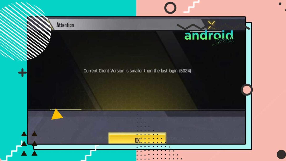
Call Of Duty Mobile recently released its Season 4, where the game brings a lot of major improvements and stability. Where a lot of players have reported the game showing the error Current Client Version is smaller than the last login (5024). Due to this, players were unable to join the game.
Today in this article we will be sharing how you can resolve such COD Mobile errors in a very efficient way. Activision acknowledges the error and they are working to rectify error code 5024. Follow the following instructions mentioned down below.
Call of Duty: Mobile ’Current Client Version is smaller than the last login. (5024) Error
Activision recently released their latest version, ensuring that you have updated your game to the latest version. The game is officially available on both the Google Play Store and Apple App Store. So without further ado, let’s check it out.
Update COD Mobile from Google Play Store
- Open the Google Play Store and then search for COD Mobile.
- Click on update/install to the latest version
- Once it is complete, launch the game.
Note: If you face a problem on an emulator, follow the similar action mentioned down below.
Alternatively,
You can update the game to the latest version using APK and OBB Package, here is the following.
- Download the COD mobile Installation package and then unzip the file.
- Then Install the APK and launch the game to create OBB File.
- Next, move the OBB and patch file to the <shared-storage>/Android/obb/com.activision.callofduty.shooter/main.2728.com.activision.callofduty.shooter.obb.
- After the launch of the game, wait for the resource installation.
- That’s it!
Update COD Mobile from App Store
- Launch App Store and search for COD Mobile.
- Next Click on Update/Get it to the latest version
- Wait for a complete installation and then launch the game.
Clear Cache for COD Mobile
- Press and hold on to the COD Mobile icon, then tap on ‘I’ to open app information
- Then click on Cache and then tap on clear the cache.
- After that, open the game and re-login to your COD Account
- That’s it!
If you still having the issue then you have to wait for the patch update which will be later released on Google Play Store and Apple App Store. Hopefully, we believe that this article remains helpful for you and have successfully rectified the problem. If you have any queries, please share them with us in the comment section down below.

Love Adhikari
Editor at AndroidGreek, I have been Positive about Everything in Life and Belive in Simple Person Living in my Space.
Решение проблем
Xerox
®
WorkCentre
®
5022/5024 Multifunction Printer
User Guide
13-35
Коды ошибок
В данном разделе приведено описание кодов ошибок.
Если из-за ошибки некорректно завершается печать или возникает неисправность аппарата,
выводится сообщение и код ошибки (xxx-xxx).
Для заданий факса код ошибки также указывается в отчете «Сведения о работе факса»
и в отчете о передаче факса в разделе недоставленных заданий .
В таблице ниже приведены коды ошибок и способы их устранения.
Note
Когда отображается код ошибки, могут быть утрачены данные печати в аппарате,
а также информация, хранящаяся в памяти аппарата.
Если отображается код ошибки, которого нет в таблице ниже, или ошибку не удается устранить после
выполнения приведенных в таблице указаний, обращайтесь в центр технической поддержки Xerox.
Номер контакта напечатан на наклейке или карточке, прикрепленной к аппарату.
Код
ошибки
Причина
Устранение
003-500
Когда используется функция «Страниц
на стороне», отпечаток не помещается
на бумагу при заданном коэффициенте
масштабирования.
Нажмите кнопку Стоп на панели
управления и измените настройку.
003-754
Произошла ошибка IPS.
Нажмите кнопку Стоп на панели
управления и отмените задание.
003-795
При уменьшении или увеличении
сканируемого оригинала под определенный
формат бумаги значение коэффициента
масштабирования выходит за
установленные пределы.
Нажмите кнопку Стоп на панели
управления и измените настройку.
003-942
В податчик вложен оригинал нестандартного
формата.
Нажмите кнопку Стоп на панели
управления и проверьте оригинал.
003-956
На стекле экспонирования размещается
оригинал нестандартного формата.
Нажмите кнопку Стоп на панели
управления и проверьте оригинал.
003-963
Если для задания копирования для
настройки Подача бумаги выбрано
значение Авто, значит формат сканируемого
оригинала больше формата бумаги для
копирования.
Нажмите кнопку Стоп на панели
управления и измените настройку.
003-972
Превышено максимальное количество
сканируемых страниц для задания
копирования или сканирования.
Для повтора операции нажмите кнопку
Старт на панели управления, для отмены
— кнопку Стоп.
Коды ошибок
В процессе работы могут появляться ошибки. За консультацией по их устранению обратитесь в техническую поддержу.
Коды ошибок с расшифровкой:
400 Ошибка формата запроса.
404 Задание с заданным uuid не найдено.
405 Задание с заданным uuid нельзя отменить.
409 Задание с заданным requestId уже существует.
5000 Некорректно указан тип запроса задания.
5002 Не удалось зарегистрировать РВ.
5003 Не корректно указан идентификационный код регистрации.
5010 Отсутствует авторизация в сервисе.
5021 Устройство с заданным ID не найдено
5022 Устройство с заданным ID не существует.
5023 Не удалось добавить устройство с заданным ID в список.
5024 Не удалось изменить настройки для устройства с заданным ID.
5025 Не удалось получить состояние РВ.
5026 Не удалось получить настройки интерфейсов обмена данными.
5028 Не удалось получить список подключѐнных устройств.
5030 Введены не верные данные адреса выбытия.
5031 Введены не верные данные кода маркировки.
5090 Внутренняя ошибка сервера.
Коды ошибок Модуля безопасности (МБ) Регистратора выбытия (РВ):
0x12 (18) Команда не поддерживается. Неверное состояние МБ РВ (Команда
не разрешена)
0x13 (19) Ошибка проверки контрольной суммы, ошибка формата и т.д.
0x15 (21) Некорректные входные данные
0x16 (22) Неверная длина входных данных
0x17 (23) Буфер заполнен
0x18 (24) Некорректный параметр команды ParamChain
0x19 (25) Некорректный параметр команды ParamMode, режим не поддерживается
0x28 (40) Требуется завершить цепочку
0x29 (41) Есть данные, цепочка не может быть завершена
0x31 (49) Формат сертификата неверен
0x32 (50) Срок действия сертификата истѐк
0x33 (51) Ошибка проверки криптограммы
0x34 (52) Превышено количество использований сеансового ключа
0x35 (53) Требуется ключ для проверки
0x41 (65) Не была проведена авторизация пользователя
0x42 (66) Не была проведена аутентификация с удаленным сервером
0x43 (67) Нарушена последовательность команд аутентификации, транзакции
0x44 (67) Некорректное сообщение (ошибка структуры, некорректный тип
данных, размер переданных данных не соответствует указанному в
заголовке сообщения)
0x75 (117) Устройства МБ РВ не готовы к работе
0x83 (131) Не все отчеты выданы
0x85 (133) Сертификат не найден
0x86 (134) Команда не разрешена, связь со спутником отсутствует более 24 часов
0x87 (135) Команда не разрешена, ПИН-код заблокирован
0xE0 (224) Рассинхронизация между элементами МБ РВ
0xE1 (225) Внутренняя ошибка МБ РВ при передаче данных
0xE2 (226) Недостаточное напряжение питания МБ РВ
Коды ошибок Регистратора выбытия:
0x101 (257) ошибка связи с сервером эмиссии
0x102 (258) Ошибка аутентификации на сервере эмиссии
0x103 (259) Ошибка связи с МБ РВ
0x104 (260) МБ РВ не готов
0x105 (261) МБ РВ не активирован
0x106 (262) МБ РВ заблокирован
0x107 (263) Некорректные параметры команды
Решение проблем
Xerox
®
WorkCentre
®
5022/5024 Multifunction Printer
User Guide
13-36
003-973
Слишком большой размер изображения,
когда уменьшается или увеличивается
сканируемый оригинал, не соответствующий
ориентации бумаги.
Выполните одно из следующих действий.
•
Уменьшите значение настройки
Уменьшить/Увеличить.
•
Измените ориентацию бумаги или
оригинала.
004-345
Произошла ошибка.
Выключите аппарат и снова включите
его после того, как погаснет дисплей.
Если снова появится данное сообщение,
обратитесь в центр технической
поддержки Xerox.
005-122
005-123
005-125
005-131
005-132
005-134
005-135
005-136
005-139
005-145
005-147
005-196
005-197
005-198
005-199
В податчике оригиналов застряла бумага.
Извлеките застрявший оригинал.
См. раздел
005-210
005-275
005-280
Ошибка податчика оригиналов.
Выключите аппарат и снова включите
его после того, как погаснет дисплей.
Если снова появится данное сообщение,
обратитесь в центр технической
поддержки Xerox.
005-305
Открыта левая крышка податчика
оригиналов.
Закройте левую крышку податчика
оригиналов.
005-500
Ошибка податчика оригиналов.
Выключите аппарат и снова включите
его после того, как погаснет дисплей.
005-907
005-908
005-913
В податчике оригиналов застряла бумага.
Извлеките застрявший оригинал.
См. раздел
005-940
Ошибка податчика оригиналов.
Нажмите кнопку Стоп на панели
управления и снова вложите оригинал
в податчик.
Код
ошибки
Причина
Устранение
 Thanks: 0
 Likes: 0
 Dislikes: 0
-
01-30-2010
#1

Junior Member
- Rep Power
- 0
Xerox 7228 error 004-345
hello together
on by xerox 7228 s found an error (system)(004-345)
does anyone know the errors?thank
-
01-30-2010
#2
This Parts & Service manual can now be purchased for $11.77 and downloaded immediately after payment from The Internet’s largest collection of manuals
Paul@justmanuals.com
-
01-31-2010
#3
Communication default between MCU and HVPS , 5 V is missing.
Cyan drum cartridge fault. Replace cyan drum.or try this:
There is +5 VDC from P/J574-5 to P/J574-4 on the HVPS Control PWB ?
Disconnect P/J574
There is +5 VDC from J574-5 to J574-4.
There is +5 VDC from P/J406-B5 on the MCU PWB to GNDCheck for open circuit or loose connections in the 5VDC supply wires between P/J406, pins B5 and B6; and P/J574, pins 5 and 4.
Check the wire from J406-B5 to J574-5 for a short circuit to GND. If the wire is OK, replace the HVPS Control PWB
Switch off the power. Check these wires for an open or short circuit to GND:
- <LI id=svc.imper.0000647840>HVPS Control PWB P/J574-9 to MCU PWB P/J406-B1.
<LI id=svc.imper.0000647844>HVPS Control PWB P/J574-8 to MCU PWB P/J406-B2.
<LI id=svc.imper.0000647848>HVPS Control PWB P/J574-7 to MCU PWB P/J406-B3 - HVPS Control PWB P/J574-6 to MCU PWB P/J406-B4.
If the problem continues, replace the MCU PWB ( PL 13.1). If this does not resolve the problem, replace the HVPS Control PWB ( PL 9.1).
- <LI id=svc.imper.0000647840>HVPS Control PWB P/J574-9 to MCU PWB P/J406-B1.
-
02-02-2010
#4
Senior Tech
100+ Posts
- Rep Power
- 0
Replace cyan drum & tell me if OK
-
02-02-2010
#5
Junior Member
- Rep Power
- 0
Hello together,
Is working since i replace the drum.
THANKS for you help


Tags for this Thread
Bookmarks
Bookmarks
Posting Permissions

- You may not post new threads
- You may not post replies
- You may not post attachments
- You may not edit your posts
- BB code is On
- Smilies are On
- [IMG] code is On
- [VIDEO] code is On
- HTML code is Off
Forum Rules
 13:58
13:58
#6 Xerox WorkCentre 5019 5021 5022 5024 бледно печатает | Чем и как заправить Xerox 006R01573
 22:46
22:46
#116 МФУ Xerox WC 5019 5021 5022 5024 замена девелопера, барабана | Восстановление 013R00670
 02:51
02:51
Replace waste toner from Xerox 5021 Part 1 YouTube
 04:13
04:13
Xerox Workcentre 5021/ 5019
 11:59
11:59
#51 Копир Xerox WorkCentre 5016 / 5020 восстановление драм картриджа | Фотобарабан Xerox 101R00432
 02:30
02:30
Xerox Printer Installation & Driver Defaults
 00:31
00:31
Разорваный резиновый вал от принтера
 10:03
10:03
Ремонт лотка подачи бумаги XEROX WC 5021
Устранение неисправностей
WorkCentre 5019/5021
Руководство пользователя
11-17
Проблемы с отпечатками
В таблице ниже приведены возможные причины проблем с отпечатками.
Признак
Вероятная причина
Устранение
Отпечатки
выполнены на
бумаге
неправильного
размера.
В указанный лоток
вложена бумага
неправильного размера.
Вложите в лоток бумагу другого размера или
измените параметры печати в соответствии
с бумагой в лотке.
Обрезание
изображения по
краям.
Размер документа
больше области печати
аппарата.
Увеличьте область печати аппарата или уменьшите
область печати документа.
Отключены
настройки для
параметров печати.
Используется драйвер
принтера для другой
модели аппарата.
Установите драйвер принтера для данного
аппарата.
На аппарате не
установлено
соответствующее
устройство.
Проверьте установленные на аппарате устройства
и выберите их в драйвере принтера, в группе
«Элементы» раздела «Опции».
На компьютере не
используется
драйвер принтера,
прилагаемый
к аппарату
(используется
драйвер другого
производителя).
Проверьте на
компьютере,
используется ли драйвер
принтера, прилагаемый
к аппарату.
Выберите на компьютере драйвер принтера,
прилагаемый к аппарату. Если драйвер принтера
отсутствует в списке для выбора, его следует
установить, а затем выбрать. При использовании
драйвера принтера другого производителя
функционирование не гарантируется.

Проблемы при сканировании, Сканирование не выполняется, Данные сканирования не загружаются на компьютер
Проблемы при сканировании -18, Здел
- Изображение
- Текст
Устранение неисправностей
WorkCentre 5019/5021
Руководство пользователя
11-18
Проблемы при сканировании
В данном разделе приведены способы устранения неисправностей, которые могут возникать
при сканировании.
Сканирование не выполняется
В таблице ниже приведены возможные причины того, что не выполняется сканирование.
Данные сканирования не загружаются на компьютер
В таблице ниже приведены возможные причины того, что данные сканирования не загружаются
на компьютер.
Признак
Вероятная причина
Устранение
Неправильная
подача оригиналов
податчиком.
Размер оригинала
слишком мал.
Минимальный формат бумаги в податчике
оригиналов: А5
.
Данный тип оригиналов
не поддерживается.
Податчик не подает оригиналы неправильной
формы, визитки, пленки или тонкие документы, а
также оригиналы с наклейками, зажимами
и липкой лентой.
См. раздел
Типы бумаги
на стр. 4-1.
Неправильно
установлены
направляющие
оригиналов.
Установите направляющие по размеру оригинала.
См. раздел
Размещение оригиналов
на стр. 6-1.
В податчике оригиналов
застряли обрывки.
Откройте крышку податчика оригиналов
и извлеките застрявшие обрывки.
См. раздел
Застревание оригиналов
на стр. 11-36.
Признак
Вероятная причина
Устранение
Не удается найти
сканер.
Питание аппарата не
включено.
Включите питание аппарата.
См. раздел
Электропитание
на стр. 3-6.
Не подключен USB-
кабель компьютера.
Подсоедините USB-кабель компьютера.
См. раздел
Интерфейс USB
на стр. 2-2.
Не подключен USB-
кабель аппарата.
Подсоедините USB-кабель аппарата.
См. раздел
Интерфейс USB
на стр. 2-2.

Проблемы с качеством изображения сканирования, Проблемы с качеством изображения сканирования -19
Страница 153
- Изображение
- Текст
Устранение неисправностей
WorkCentre 5019/5021
Руководство пользователя
11-19
Проблемы с качеством изображения сканирования
В таблице ниже приведены возможные причины проблем с качеством изображения
сканирования.
Не удается
загрузить данные
со сканера из-за
ошибки связи
с драйвером
TWAIN.
Драйвер сканера не
установлен.
Установите драйвер сканера.
Остановлено
выполнение
операции при
загрузке данных.
Слишком большой
размер файла.
Уменьшите настройку разрешения и попробуйте
снова загрузить данные.
Признак
Вероятная причина
Устранение
Загрязнение
изображения
сканирования.
Загрязнение стекла
экспонирования или его
крышки.
Очистите стекло экспонирования или его крышку.
См. раздел
Чистка стекла экспонирования и его
крышки
на стр. 10-9.
Копируется пленка или
прозрачный материал.
Если загрязнена крышка стекла экспонирования,
при сканировании прозрачных оригиналов это
отражается на отпечатках. Перед сканированием
накройте оригинал листом белой бумаги.
Копируется оригинал на
цветной или грубой
бумаге, либо светокопия.
Перед сканированием настройте плотность
сканирования или качество изображения.
Сканируемый оригинал
напечатан на глянцевой
бумаге.
Глянцевая бумага легко прилипает к стеклу
экспонирования, и на отпечатках могут
воспроизводиться тени. Перед сканированием
подложите под оригинал прозрачный лист или
пленку.
Изображение
слишком светлое
или слишком
темное.
Неправильно настроена
плотность сканирования.
Настройте плотность сканирования.
Неподходящий тип
оригинала.
Выберите подходящий тип оригинала.
Пробелы на
изображении.
Мятый оригинал или
оригинал с наклеенными
фрагментами.
Мятый оригинал или оригинал с наклеенными
фрагментами может неплотно прилегать к стеклу
экспонирования. Чтобы добиться правильного
прилегания оригинала к стеклу экспонирования,
прижмите его сверху стопкой белой бумаги.
Признак
Вероятная причина
Устранение

Устранение неисправностей
WorkCentre 5019/5021
Руководство пользователя
11-20
Размер
изображения не
соответствует
ожидаемому
размеру.
Загрязнение стекла
экспонирования или его
крышки.
Очистите стекло экспонирования или его крышку.
См. раздел
Чистка стекла экспонирования и его
крышки
на стр. 10-9.
Копируется пленка или
прозрачный материал.
Перед сканированием накройте оригинал листом
белой бумаги.
Сдвиг копий.
Поместите оригинал правильно.
См. раздел
Размещение оригиналов
на стр. 6-1.
Направляющие
в податчике оригиналов
установлены
неправильно.
Правильно разместите оригинал и установите
направляющие так, чтобы они касались оригинала.
См. раздел
Размещение оригиналов
на стр. 6-1.
Оригинал со складками.
Распрямите оригинал и поместите его правильно.
Зернистое
изображение.
Установлено низкое
разрешение.
Установите более высокое разрешение.
См. раздел
Размещение оригиналов
на стр. 6-1.
Признак
Вероятная причина
Устранение

Устранение неисправностей
WorkCentre 5019/5021
Руководство пользователя
11-21
Коды ошибок
Если из-за ошибки некорректно завершается печать или возникает неисправность аппарата,
мигает код ошибки (X-X) или (XXX-XXX).
Примеры отображения кодов ошибки
В таблице ниже приведены коды ошибок и способы их устранения.
Примечания
•
Когда отображается код ошибки, могут быть утрачены данные печати в аппарате,
а также информация, хранящаяся в памяти аппарата.
•
Если отображается код ошибки, которого нет в таблице ниже, или ошибку не
удается устранить после выполнения приведенных в таблице указаний,
обращайтесь в центр технической поддержки Xerox. Номер контакта напечатан на
наклейке или карточке, прикрепленной к аппарату.
•
Когда отображает двухзначный код (X-X), можно проверить соответствующий
шестизначный код (XXX-XXX), нажав и удерживая кнопку
Копия удостоверения.

Устранение неисправностей
WorkCentre 5019/5021
Руководство пользователя
11-22
Код ошибки (X-X)
Код ошибки
Причина
Устранение
A-1
Застревание оригинала
в податчике.
Извлеките застрявший оригинал.
См. раздел
Застревание оригиналов
на
стр. 11-36.
A-2
Размер оригиналов в податчике не
поддерживается.
Поместите данный оригинал на стекло
экспонирования.
См. раздел
Застревание оригиналов
на
стр. 11-36.
Если оригинал застрял, извлеките его.
См. раздел
Застревание оригиналов
на
стр. 11-36.
A-3
Не удается определить размер
оригинала.
Проверьте следующее:
— В податчике находятся только оригиналы.
— Направляющие установлены по размеру
оригинала.
— Все оригиналы одинакового размера.
Нельзя вкладывать одновременно
оригиналы разного размера. Для работы
с оригиналами разного размера пользуйтесь
стеклом экспонирования.
Чтобы продолжить выполнение работы,
заново вложите оригиналы, которые не были
скопированы или отсканированы, и нажмите
кнопку
Старт.
См. раздел
Размещение оригиналов
на
стр. 5-1.
A-5
Открыта крышка податчика
оригиналов.
Закройте крышку.
См. раздел
Компоненты аппарата
на стр. 3-1.
C-0
Отсутствует лоток для автовыбора
или нет бумаги подходящего
размера в выбранном лотке.
Сначала выберите лоток из тех, у которых
светится индикатор, нажав кнопку
Снабжение бумагой, и выдвиньте данный
лоток.
Затем вложите бумагу, размер и ориентация
которой отображаются в области индикации
на схеме состояния аппарата, и нажмите
кнопку
Старт.
Для отмены работы нажмите кнопку
Стоп.
См. раздел
Загрузка бумаги в лотки
на
стр. 4-8.
C-1
Нет бумаги в лотке 1.
Снова загрузите бумагу в лоток 1. Если лоток
пуст, загрузите бумагу.
См. раздел
Загрузка бумаги в лоток 1 и лоток
2 (дополнительный)
на стр. 4-8.

Устранение неисправностей
WorkCentre 5019/5021
Руководство пользователя
11-23
C-2
Нет бумаги в лотке 2.
Снова загрузите бумагу в лоток 2. Если лоток
пуст, загрузите бумагу.
См. раздел
Загрузка бумаги в лоток 1 и лоток
2 (дополнительный)
на стр. 4-8.
C-3
Нет бумаги в обходном лотке.
Заново вложите бумагу в обходной лоток.
Если лоток пуст, загрузите бумагу.
См. раздел
Загрузка бумаги в обходной
лоток
на стр. 4-10.
C-5
Размер и ориентация бумаги
в лотке 1 не соответствуют
настройкам аппарата.
Убедитесь, что размер и ориентация бумаги
в лотке 1 соответствуют настройкам,
отображаемым в области индикации на
схеме состояния аппарата, заново вложите
бумагу и установите направляющие
в правильное положение.
См. раздел
Загрузка бумаги в лоток 1 и лоток
2 (дополнительный)
на стр. 4-8.
Если настройка размера или ориентации
бумаги изменились, сначала отмените
работу кнопкой
Стоп.
См. раздел
Изменение размера бумаги для
лотка 1 и 2
на стр. 4-12.
C-6
Размер и ориентация бумаги
в лотке 2 не соответствуют
настройкам аппарата.
Убедитесь, что размер и ориентация бумаги
в лотке 2 соответствуют настройкам,
отображаемым в области индикации на
схеме состояния аппарата, заново вложите
бумагу и установите направляющие
в правильное положение.
См. раздел
Загрузка бумаги в лоток 1 и лоток
2 (дополнительный)
на стр. 4-8.
Если настройка размера или ориентации
бумаги изменились, сначала отмените
работу кнопкой
Стоп.
См. раздел
Изменение размера бумаги для
лотка 1 и 2
на стр. 4-12.
Код ошибки
Причина
Устранение

Устранение неисправностей
WorkCentre 5019/5021
Руководство пользователя
11-24
C-7
Размер и ориентация бумаги
в обходном лотке не соответствуют
настройкам аппарата.
Убедитесь, что размер и ориентация бумаги
в обходном лотке соответствуют настройкам,
отображаемым в области индикации на
схеме состояния аппарата, заново вложите
бумагу и установите направляющие
в правильное положение.
См. раздел
Загрузка бумаги в обходной
лоток
на стр. 4-10.
Если настройка размера или ориентации
бумаги изменились, сначала отмените
работу кнопкой
Стоп.
См. раздел
Изменение размера бумаги для
лотка 1 и 2
на стр. 4-12.
C-9
При копировании в режиме
«Страниц на листе» значение
масштаба, требуемое для
размещения указанного числа
страниц на листе, выходит за
пределы диапазона 25 — 400%.
Нажмите кнопку
Стоп.
Измените масштаб так, чтобы все страницы
могли разместиться на листе, поместите все
оригиналы и нажмите кнопку
Старт.
E-1
Застревание бумаги за левой
крышкой аппарата.
Откройте левую крышку аппарата
и извлеките застрявшую бумагу.
См. раздел
E-1. Застревание бумаги за левой
крышкой A
на стр. 11-30.
E-2
Застревание бумаги за крышкой
однолоткового модуля аппарата.
Откройте крышку однолоткового модуля
аппарата и извлеките застрявшую бумагу.
См. раздел
E-2: Застревание бумаги
в однолотковом модуле B
на стр. 11-32.
E-3
Застревание бумаги в лотке 1.
Извлеките застрявшую бумагу.
См. раздел
E-3. Застревание бумаги в лотке 1
на стр. 11-33.
E-4
Застревание бумаги в лотке 2.
Извлеките застрявшую бумагу.
См. раздел
E-4. Застревание бумаги в лотке 2
на стр. 11-34.
E-5
Застревание бумаги в обходном
лотке.
Извлеките застрявшую бумагу.
См. раздел
E-5. Застревание бумаги
в обходном лотке
на стр. 11-35.
E-6
Открыта левая крышка аппарата.
Закройте крышку.
См. раздел
Компоненты аппарата
на стр. 3-1.
E-7
Открыта передняя крышка
аппарата.
Закройте крышку.
См. раздел
Компоненты аппарата
на стр. 3-1.
E-8
Открыта крышка однолоткового
модуля аппарата.
Закройте крышку.
См. раздел
Компоненты аппарата
на стр. 3-1.
Код ошибки
Причина
Устранение

Устранение неисправностей
WorkCentre 5019/5021
Руководство пользователя
11-25
E-9
При текущей настройке
изображение будет обрезаться.
Поместите оригинал в горизонтальной
ориентации и нажмите кнопку
Старт.
Примечание.
Если используется податчик
оригиналов, заново вложите в него все
оригиналы, не открывая крышку стекла
экспонирования.
H-0
Идет охлаждение внутри аппарата.
Запускается автоматически. Не открывайте
никакие крышки аппарата.
J-1
Закончился тонер.
Замените тонер-картридж.
См. раздел
Замена тонер-картриджа
на
стр. 10-3.
J-4
Необходимо заменить принт-
картридж.
Выключите питание, подождите 10 секунд
после того, как погаснет экран, затем снова
включите питание.
Если это изображение не снимается со схемы
состояния аппарата, замените принт-
картридж.
См. раздел
Замена принт-картриджа
на
стр. 10-6.
J-6
Неисправен принт-картридж.
Замените принт-картридж.
См. раздел
Замена принт-картриджа
на
стр. 10-6.
J-7
Истек гарантийный срок принт-
картриджа по качеству
изображения.
Качество изображения может ухудшиться.
Рекомендуется заменить принт-картридж.
См. раздел
Замена принт-картриджа
на
стр. 10-6.
J-8
Истек гарантийный срок
функционирования принт-
картриджа.
Это может привести к повреждению
аппарата. Замените принт-картридж.
См. раздел
Замена принт-картриджа
на
стр. 10-6.
J-9
Неисправен принт-картридж.
Срочно замените принт-картридж.
В противном случае возможно повреждение
аппарата.
См. раздел
Замена принт-картриджа
на
стр. 10-6.
L-1
Исчерпан лимит копий, если он
установлен. Кроме того, активен
сеанс пользователя, исчерпавшего
лимит копий.
Нажмите кнопку
Стоп и обратитесь
к системному администратору.
n-1
Работа отменена из-за нехватки
памяти при чтении.
Изменив настройку, попробуйте снова.
n-2
Работа отменена.
Изменив настройку, попробуйте снова.
Код ошибки
Причина
Устранение

Устранение неисправностей
WorkCentre 5019/5021
Руководство пользователя
11-26
Код ошибки (XXX-XXX)
Код ошибки Причина
Устранение
004-345
Произошла ошибка.
Выключите аппарат и снова включите его
после того, как погаснет дисплей.
005-210
Произошла ошибка.
Выключите аппарат и снова включите его
после того, как погаснет дисплей. Если снова
появится данный код ошибки, обратитесь
в центр технической поддержки Xerox.
005-275
Произошла ошибка.
Выключите аппарат и снова включите его
после того, как погаснет дисплей.
005-280
Произошла ошибка.
Выключите аппарат и снова включите его
после того, как погаснет дисплей. Если снова
появится данный код ошибки, обратитесь
в центр технической поддержки Xerox.
005-500
Произошла ошибка.
Выключите аппарат и снова включите его
после того, как погаснет дисплей.
005-940
Ошибка податчика оригиналов.
После завершения копирования выполните
следующие действия: нажмите любую кнопку
на панели управления и выполните новую
работу или дождитесь завершения тайм-аута
для сброса ошибки.
010-311
010-312
010-320
010-327
010-392
Произошла ошибка.
Выключите аппарат и снова включите его
после того, как погаснет дисплей. Если снова
появится данный код ошибки, обратитесь
в центр технической поддержки Xerox.
016-500
016-501
016-502
016-504
016-571
016-742
016-744
Произошла ошибка.
Выключите аппарат и снова включите его
после того, как погаснет дисплей.
016-776
Работа отменена.
Изменив настройку, попробуйте снова.

Комментарии
 Loading…
![]()
Xerox® WorkCentre 5022/5024
Service Manual
Revised June 2014 702Pxxxxx

WC 5022/5024
Service Documentation
WC 5022/5024 Service Documentation
702P02828
Version 1.0
06/2014
Published by Xerox. 800 Phillips Road, Webster, NY 14580
© 2014 by Xerox Co. All rights reserved. Xerox® and all identifying numbers used in connection with the Xerox products mentioned in this publication are trademarks of the Xerox Corporation.
***Xerox Private Data***
All service documentation is supplied to Xerox external customers for informational purposes only. Xerox service documentation is intended for use by certified, product-trained service personnel only. Xerox does not warrant or represent that it will notify or provide to such customer any future change to this documentation. Customer performed service of equipment, or modules, components, or parts of such equipment may affect whether Xerox is responsible to fix machine defects under the warranty offered by Xerox with respect to such equipment. You should consult the applicable warranty for its terms regarding customer or third-party provided service.
Xerox
While Xerox has tried to make the documentation accurate, Xerox will have no liability arising out of any inaccuracies or omissions.
WARNING
This equipment generates, uses and can radiate radio frequency energy, and if not installed and used in accordance with the instructions documentation, may cause interference to radio communications. It has been tested and found to comply with the limits for a Class A computing device pursuant to subpart J of part 15 of FCC rules, which are designed to provide reasonable protection against such interference when operated in a commercial environment. Operation of this equipment in a residential area is likely to cause interference in which case the user, at his own expense, will be required to correct the interference.
|
Version 1.0 |
06/2014 |
Preface |
|
WC 5022/5024 |
0-1 |
Chapter 0 Introduction

0 Introduction
|
0.1 |
Getting to know this Service Manual……………………………………………………………… |
0-3 |
|
0.2 |
How to use the Service Manual ……………………………………………………………………. |
0-3 |
|
0.3 |
Description for Terminology And Symbols ……………………………………………………… |
0-4 |
|
Version 1.0 |
06/2014 |
Introduction |
|
WC 5022/5024 |
0-1 |

0.1 Getting to know this Service Manual
This manual is used as the standard service manual for WorkCentre 5022/5024.
•Publication Comment Sheet
Enter any comments and/or corrections regarding this service manual into the Publication Comment Sheet, and send it to the following department.
Solution Service & Operational Management CS Dept.
0.2 How to use the Service Manual
This manual describes the standard procedures for the servicing this product. Refer to Chapter 1 Service Call Procedure for efficient and effective servicing during maintenance calls.
For more information on the options, refer to the options manual.
0.2.1 Contents of Manual
This manual is divided into 10 chapters as described below.
•Chapter 1 Service Call Procedure
This chapter describes the general work and servicing procedures for the maintenance of this product.
•Chapter 2 Troubleshooting
This chapter describes the troubleshooting procedures other than image quality troubleshooting for this product.
•Chapter 3 Image Quality Troubleshooting
This chapter describes the image quality troubleshooting procedures for this product.
•Chapter 4 Disassembly/Assembly and Adjustment
This chapter describes the disassembly, assembly, adjustment and replacement procedures for components of this product.
•Chapter 5 Parts List
This chapter contains the spare parts information for this product.
•Chapter 6 General
This chapter contains the following information.
6.1Specifications
6.2Tools/Service Consumables/Consumables
6.3Service Data
6.5 Service Mode
6.8Fax-related Information
•Chapter 7 Wiring Data
This chapter contains the information about the Wiring Connector List/Locations, the Wiring Data, and the BSD for this machine.
•Chapter 8 Accessories (not yet issued)
•Chapter 9 Installation/Removal
This chapter contains the installation and removal procedures for this product and the options that are specific to it.
•Chapter 10 Mechanism & Functions Overview (not yet issued)
0.2.2 Information on Updating
This manual will be sent to each Service Center as specified below. Revisions must be incorporated correctly to keep the manual up-to-date.
Updating Procedure:
•When the manual is updated, the issue number ‘Ver. 1’ will be changed to Ver. 1.1, Ver. 1.2, and so on.
|
06/2014 |
Introduction |
|
0.1 Getting to know this Service Manual |
||
|
0-3 |

0.3 Description for Terminology And Symbols
The terms and symbols used throughout this manual are explained here.
•The terms and symbols used at the beginning of a text are defined as follows:
WARNING
Indicates an imminently hazardous situation, such as death or serious injury if operators do not handle the machine correctly by disregarding the statement.
WARNING
Indicates a potentially hazardous situation, such as death or serious injury if operators do not handle the machine correctly by disregarding the statement.
CAUTION
Indicates a potentially hazardous situation, such as injury or property damage if operators do not handle the machine correctly by disregarding the statement.
Instruction: Used to alert you to a procedure which, if not strictly observed, could result in damage to the machine or equipment.
NOTE: Used when work procedures and rules are emphasized.
Used when other explanations are given.
Used to describe the purposes of Adjustment and Troubleshooting.
REP: Indicates the disassembly/assembly procedure for reference.
ADJ: Indicates the adjustment procedure for reference.
PL: Indicates the parts list for reference.
Terminology
Table 1 Terminology |
|
Terminology |
Description |
Assy |
Means Assembly. |
TEC Value |
Abbreviation of Typical Electricity Consumption, which means the stan- |
|
dard power consumption. Read as ‘tec’. |
|
Installation of any part other than the ones designated by Xerox shall be strictly prohibited because it cannot be guaranteed in quality and safety.
Important Information Stored Component (ISC)
This component stores all the important customer information that is input after the installation. When performing replacement, follow the procedures in ‘Chapter 4 Disassembly/Assembly and Adjustment’ to replace/discard. Make absolutely sure that no customer information gets leaked outside.
|
Introduction |
06/2014 |
|
0.3 Description for Terminology And Symbols |
||
|
0-4 |
Chapter 1 Service Call Procedures

1 Service Call Procedures
|
1.1 Before Starting the Servicing ……………………………………………………………………….. |
1-3 |
1.2 Service Call Procedure
|
1.2.2 Service Call Procedure …………………………………………………………………………….. |
1-5 |
|
|
1.3 |
Detailed Contents of the Service Call ……………………………………………………………. |
1-5 |
|
1.4 |
TRIM Check List…………………………………………………………………………………………. |
1-6 |
|
1.5 |
Periodic Replacement Parts/Consumables List ………………………………………………. |
1-6 |
|
Version 1.0 |
06/2014 |
Service Call Procedures |
|
WC 5022/5024 |
1-1 |

1.1 Before Starting the Servicing
1.1.1 Safety
To prevent any accident that may occur during a maintenance service, any warning or any caution regarding the servicing must be strictly observed. Do not perform any hazardous operation.
1.Power Supply
To prevent electrical shocks, burns, or injury, etc., be sure to switch OFF the machine and disconnect the plug before starting the maintenance service. If the machine has to be switched ON, such as when measuring the voltage, take extra care not to get an electrical shock.
2.Drive Area
Never inspect, clear or lubricate the drive area such as chain belts, chain wheel or gears during the machine operation.
3.Heavy Parts
Position your hip lower when removing or installing heavy parts.
4.Safety Device
See that safety devices for preventing mechanical accidents, such as fuses, circuit breakers, interlock switches, etc., and those for protecting customers from injury, such as panels and covers, function properly. Modifications that hinder the function of any safety devices are strictly prohibited.
5.Installing and Removing Parts
The edge of parts and covers may be sharp, take care not to touch them. Be careful not to touch those parts, and wipe off any oil that may have adhered to your fingers or hands before servicing. When removing parts, cables, and etc. do not pull them out by force but remove them slowly.
6.CAUTION:
RISK OF EXPLOSION IF BATTERY IS REPLACED BY AN INCORRECT TYPE. DISPOSE OF USED BATTERIES ACCORDING TO THE INSTRUCTIONS.
7.Specified Tools
Follow the instruction when a tool is specified.
8.Cleaning the Toner and Developer
11.Harmful Laser
The customer or service personnel would not be exposed to any harmful laser during the usual copying or scanning of documents. However, if a customer finds that the lamp that is used for exposing documents is too bright when performing platen copy or scan, it is possible to block the light from the platen glass by covering the portion of the platen document area that is usually not used for copying or scanning documents.
As the toner can be explosive, sweep or brush the spilled toner into a container for collecting the sweepings.
Clean away the remaining toner with a damp cloth or use a standard vacuum cleaner that is toner-tolerant. Never use the customer’s vacuum cleaner.
Do the same when cleaning the Developer because it also contains some toner.
9.Organic Solvents
When using an organic solvent such as the Drum Cleaner or Machine Cleaner, pay attention to the following:
•Ensure good ventilation in the room to prevent too much inhalation of solvent fumes.
•Do not use heated solvent.
•Keep it away from fire.
•Wash your hands thoroughly after use.
10.Modifications to the Machine
Before altering the machine, submit the irregular use license application.
|
Version 1.0 |
06/2014 |
Service Call Procedures |
1.1 Before Starting the Servicing |
||
|
WC 5022/5024 |
1-3 |

1.1.2 Things to Take Note When Handling Customer Information
1.Handling of customer’s electronic information — samples of copy/print/received fax (paper data), log files (Activity Report), and etc.
Before you bring back any samples for the purpose of investigation/analysis, always obtain permission from the customer. Make sure to assure them that the data will not be used for any other purpose. When requesting for a retrieval application from the customer, either use the [Data Security Regulations: Annex 15 — Confidential Information/Personal Information Request Form (IS-019)] or use a letterhead that has been specified by the customer after obtaining their agreement.
2.Handling of a PWB, etc. that contains customer information.
Data such as Fax Address Numbers and URLs that are registered in the customer’s machine are all important customer information. These types of information are stored in the PWB, etc. within the machine. Take extra care when handling them.
a.In case of replacements, transfer the data to the new PWB and make sure that all data in the old parts is thoroughly erased before disposing it. Make sure that no important customer information gets leaked. (For details, refer to the preface in Chapters 4 and 5)
b.If a component was replaced and it was not found to be the cause of the malfunction, return it to the machine it came from. (For components that were temporarily installed/removed for troubleshooting, etc. clear the data using the CE Mode, etc.)
3.Security related NVM values that were changed during maintenance.
If any security related NVM values, such as polling, were set for test purposes, make sure you return them to their original values after the test. (E.g.: for the details on polling that is common to all machine types, refer to FTO 2-202)
4.When connecting our company machine to the customer’s network during maintenance, make sure that you have gone through the person-in-charge to obtain permission from the customer’s systems administrator (or person-in-charge) before proceeding.
5.Follow the safety guidelines established within the OpCo and ensure that customer data do not get leaked out when servicing.
1.1.3 Other Precautions
Pay attention to the following when performing maintenance service to avoid wrong or redundant servicing:
1.Reference Materials
Before performing maintenance servicing, read all relevant technical materials such as SB, FTI, or FTO to make a systematic approach.
2.Disassembling
Make sure to check the assembled condition before removing parts or disassembling the machine.
3.Installation/Adjustment
After the installation or adjustment is complete, check that no parts or tools are left inside or on the assemblies before using the machine.
4.Handling of replaced parts/consumables
Make sure that the replaced parts or consumables as well as their packaging materials are collected back to the Service Center.
For the separation and processing methods for the collected items, refer to the Common Technical Information No. 2-027 for all machines.
• Drum Cleaner
WARNING
Never discard the Drum Cleaner into a fire. Always keep it away from open flames to prevent it from catching and causing a fire. Always dispose of the Drum Cleaner after it is completely used up. For recyclable parts, fill the necessary items in the [U-TAG] and perform collection.
5.General Precautions
•Take care not to disturb the customer’s daily work.
•Place a drop cloth or paper on the floor of the service area to keep the site clean.
•Throw any trash generated during the maintenance service into a trash bag and bring them back to the Service Center.
•Record clearly the service details and the consumables and parts replaced at visit in the Machine Service Log.
|
Service Call Procedures |
06/2014 |
Version 1.0 |
|
1.1 Before Starting the Servicing |
||
|
1-4 |
WC 5022/5024 |
![]()
1.2.2 Service Call Procedure
1.2.2.1 Initial Actions
1.Ask the operator(s) about the machine condition.
2.Record the billing meter readings.
3.Inspect any error copies, then check the machine.
4.Check the Service Log.
1.2.2.2 When UM is requested, perform the following:
1.Check the problem status by performing the Level 1 Troubleshooting in [Chapter 2 Troubleshooting].
2.Perform the applicable Level 2 Troubleshooting FIP in [Chapter 2 Troubleshooting].
3.If there are no applicable items, troubleshoot by referring to [Chapter 7 BSD].
4.Check the copy quality.
Make several sheets of copies using the Test Chart (499T 00247), then check the quality of the copies for problems.
5.Output the following [Error History Report] and check the [System Fail History] and [Paper Jam History] in order to understand the machine status.
a.Press the <Machine Status> button.
b.Select [Print Report], then press the <OK> button.
c.Select the [Error History Report], then press the<OK> button.
NOTE: When replacing parts that will incur cost to the customer, obtain the customer’s agreement before performing the replacement.
6.Repair all the secondary problems.
7.Perform TRIM Service.
1.2.2.3 When SM is requested, perform the following:
1.Check the copy quality.
Make several sheets of copies using the Test Chart (499T 00247), then check the quality of the copies for problems.
2.Output the [Error History Report] and check the [System Fail History] and [Paper Jam History] in order to understand the machine status.
•For how to output the [Error History Report], refer to [1.2.2.2 When UM is requested, perform the following:].
NOTE: When replacing parts that will incur cost to the customer, obtain the customer’s agreement before performing the replacement.
3.Perform TRIM Service.
1.2.2.4 Final Actions
1.Check overall operation/features.
2.Check the machine exterior and consumables.
3.Train the operator as required.
4.Complete the Service Log and Service Report.
5.Keep the copy samples with the Service Log.
1.3 Detailed Contents of the Service Call
1.3.1 Initial Actions
1.Ask the operator(s) about the machine condition.
•How often and where do paper jams have been occurring recently
•How is the copy quality
2.Record the copy meter readings.
3.Inspect any error copies, then check the machine.
4.Check the print samples from previous service calls and the Service Log.
1.3.2 Checking Reproducibility of Problem
1.Check the problem status by performing the Level 1 Troubleshooting in [Chapter 2 Troubleshooting].
2.Perform the applicable Level 2 Troubleshooting FIP in [Chapter 2 Troubleshooting].
3.If there are no applicable items, troubleshoot by referring to [Chapter 7 BSD].
1.3.3 Checking Copy Quality
1.Make several sheets of copies using the Test Chart (499T 00247), then check the quality of the copies.
1.3.4 TRIM Servicing
Perform TRIM servicing during a service call to maintain the machine performance.
1.Follow the TRIM Check List to perform the required TRIM items.
2.Check for parts that require periodical cleaning/replacement (consumables, parts) by referring to the TRIM Chec List, the Periodic Replacement Parts/Consumables List, and the Maintenance Report, and clean them if necessary. After a replacement, make sure that you enter the CE Mode and use [HFSI Read / Clear] to clear the applicable counter(s).
|
Version 1.0 |
06/2014 |
Service Call Procedures |
1.2.2 Service Call Procedure |
||
|
WC 5022/5024 |
1-5 |

1.4TRIM Check List
C:Perform checking. Clean, replace, or feed if necessary.
O:Always perform cleaning and checking.
*: Always perform replacement service at the specified interval.
Table 1 |
||||
|
Every |
||||
|
No. |
Servicing Items |
time |
Service Details |
|
|
1.1 |
Pre-servicing Check |
C |
• |
Activate the machine and check that abnormal |
|
(Check the machine |
noise is not heard. |
|||
|
operation sound) |
||||
|
1.2 |
Pre-servicing Check |
C |
• |
Make several sheets of copies using the Test |
|
(Copy and print the |
Chart (499T 00247), then check the quality of the |
|||
|
Test Chart) |
copies. |
|||
|
2 |
Clean the interior of |
C |
• |
Clean any paper dust and toner residue in the |
|
the machine |
paper path and on the jam sensor. |
|||
|
(Clean the paper |
• |
Especially, clean the operation section of the |
||
|
transport system) |
operator carefully. |
|||
|
3 |
Cleaning the IIT |
C |
• |
Clean the Platen Glass surface and the Platen |
|
Cushion with the optical cleaning cloth. |
||||
|
4 |
Clean the DADF |
C |
• |
Clean the Feed Roll, Nudger Roll, and Retard Roll |
|
with a cloth that has been wrung dry. |
||||
|
• |
Clean the DADF Platen Glass with the optical |
|||
|
cleaning cloth. |
||||
|
5 |
Safety Check |
O |
• |
Make sure that the power plug is plugged in prop- |
|
erly. |
||||
|
• |
Make sure that the power cords are not cracked |
|||
|
and no wires are exposed. |
||||
|
• |
Make sure that no extension cord with insufficient |
|||
|
length or power cord outside the specification, |
||||
|
such as an off-the-shelf power strip, is being used. |
||||
|
• |
Make sure that a single socket does not have mul- |
|||
|
tiple power plugs plugged into it. |
||||
|
6.1 |
Post-servicing check |
C |
• |
Make several sheets of copies using the Test |
(Copy Quality Check) |
Chart (499T 00247), then check if the quality sat- |
|||
|
isfies the specification. |
||||
|
6.2 |
Post-servicing check |
C |
• |
Check the paper feed and abnormal noise. |
|
(Check the machine |
||||
|
operation) |
||||
|
6.3 |
Post-servicing check |
C |
• |
Create the Service Log and Service Report. |
(Check the meter) |
||||
1.5 Periodic Replacement Parts/Consumables List
When servicing, check the number of copies and number of fed sheets for the consumables and parts that require periodical cleaning/replacement. Clean or replace them if necessary. The history can be checked by printing the Maintenance Report or by checking the approriate counter in [HFSI Read / Clear] in CE Mode (6.4.2.9 HFSI Read / Clear).
For the items that cannot be checked in CE Mode, clean or replace them according to the replacement intervals (standard PV).
CAUTION
Do not place the imaging materials, such as the Toner and the Drum, in the car for a long time.
NOTE: Clean the Platen Glass with a Platen Wax Cleaner 499D 00194 (194D) every 10K Feeds.
Table 1
|
HFSI |
||||
|
Parts/Consumables Name/ |
[Chain- |
Replacement |
||
|
No |
PL No. |
Link] |
Interval |
Check the counter |
|
1 |
Tray 1 Feed No. |
950-803 |
50,000PV |
1 Feed = 1 Count Up. |
|
Tray 1 Feed Roll / Retard |
Replace both at the same |
|||
|
Pad |
time. |
|||
|
(PL 9.2) |
||||
|
2 |
Tray 2 Feed No. |
950-804 |
300,000PV |
1 Feed = 1 Count Up. |
|
Tray 2 Feed Roll/Nudger |
Replace all 3 at the same |
|||
|
Roll/Retard Roll |
time. |
|||
|
(PL 10.3) |
||||
|
3 |
Tray 3 Feed No. |
950-808 |
300,000PV |
1 Feed = 1 Count Up. |
|
Tray 3 Feed Roll/Nudger |
Replace all 3 at the same |
|||
|
Roll/Retard Roll |
time. |
|||
|
(PL 11.3) |
||||
|
4 |
Tray 4 Feed No. |
950-809 |
300,000PV |
1 Feed = 1 Count Up. |
|
Tray 4 Feed Roll/Nudger |
Replace all 3 at the same |
|||
|
Roll/Retard Roll |
time. |
|||
|
(PL 11.3) |
||||
|
5 |
MSI Feed Count |
950-802 |
50,000PV |
1 Feed = 1 Count Up. |
|
MSI Feed Roll/MSI Nudger |
Replace all 3 at the same |
|||
|
Roll/MSI Retard Pad |
time. |
|||
|
(PL 13.3) |
||||
|
6 |
Fusing Unit |
950-801 |
175,000PV |
1 pass through the Fusing |
|
(PL 7.1) |
Unit Exit Sensor = 1 Count |
|||
|
Up. |
||||
|
7 |
BTR Unit |
950-800 |
100,000PV |
1 pass through the Fusing |
|
(PL 6.1) |
Unit Exit Sensor = 1 Count |
|||
|
Up. |
||||
|
Service Call Procedures |
06/2014 |
Version 1.0 |
1.4 TRIM Check List |
||
|
1-6 |
WC 5022/5024 |

Table 1
|
HFSI |
||||
|
Parts/Consumables Name/ |
[Chain- |
Replacement |
||
|
No |
PL No. |
Link] |
Interval |
Check the counter |
|
8 |
Document Feed No. |
955-806 |
200,000PV |
Replace the Feed Roll, |
DADF Feed Roll/Nudger Roll |
Nudger Roll, and Retard Pad |
|||
|
(PL 56.5) |
at the same time. |
|||
DADF Retard Pad |
NOTE: Clean the Platen |
|||
|
(PL 56.13) |
||||
|
Glass with a Platen Wax |
||||
|
Cleaner 499D 00914 (194D) |
||||
|
every 10K Feeds. |
||||
|
9 |
Toner Cartridge |
— |
9,000PV |
|
|
(PL 8.1) |
||||
|
10 |
Low Capacity Toner Car- |
— |
5,000PV |
|
|
tridge |
||||
|
(PL 8.1) |
||||
|
13 |
Drum Cartridge *1 |
950-807 |
343k cycle |
|
|
(PL 8.1) |
66,000PV |
|||
|
(22PPM) |
||||
|
78,000PV |
||||
|
(24PPM) |
||||
|
15 |
Cartridge Guide |
— |
300,000PV |
|
|
(PL 8.2) |
||||
*1 As the PV may differ greatly from the target value depending on the usage conditions, it should only be regarded as a reference value.
|
Version 1.0 |
06/2014 |
Service Call Procedures |
|
1.5 Periodic Replacement Parts/Consumables List |
||
|
WC 5022/5024 |
1-7 |
Chapter 2 Troubleshooting

|
2 Troubleshooting |
||||||
|
2.1 Introduction |
CHAIN 10 |
|||||
|
2.1.1 |
How to Troubleshoot ………………………………………………………………………………… |
2-5 |
010-311 |
Fusing Unit Center Thermistor Defect…………………………………………………….. |
2-27 |
|
|
2.1.3 |
Glossary …………………………………………………………………………………………………. |
2-5 |
010-312 |
Fusing Unit Rear Thermistor Defect……………………………………………………….. |
2-27 |
|
|
2.2 Product FIP |
010-320 |
Over Heat Temperature Fail …………………………………………………………………. |
2-28 |
|||
|
010-327 |
Fusing Unit On Time Fail |
2-28 |
||||
|
2.2.1 Level 1 FIP |
010-379 |
Fusing Unit Hot Not Ready Return Time Fail…………………………………………… |
2-29 |
|||
|
010-392 NOHAD Fan Defect |
2-29 |
|||||
|
2.2.1.1 Level 1 FIP |
2-7 |
|||||
|
010-602 Over Temp Cooling Mode |
2-30 |
|||||
2.2.2 Level 2 FIP
CHAIN 3
|
003-500 N-Up NG Out Of Range ……………………………………………………………………….. |
2-9 |
|
|
003-754 IPS Overrun ……………………………………………………………………………………….. |
2-9 |
|
|
003-795 AMS NG Out Of Range………………………………………………………………………… |
2-10 |
|
|
003-942 Not-Supported Doc Size ………………………………………………………………………. |
2-10 |
|
|
003-956 |
Not-Supported Doc Size ………………………………………………………………………. |
2-11 |
|
003-963 |
APS NG Out Of Range ………………………………………………………………………… |
2-11 |
|
003-972 |
1Job Max Page Over …………………………………………………………………………… |
2-12 |
|
003-973 |
Auto Rotation NG Out Of Range……………………………………………………………. |
2-12 |
CHAIN 4
|
004-345 HVPS Communication Error …………………………………………………………………. |
2-13 |
CHAIN 5
|
005-122 DADF Simplex/Side 1 Pre Regi Sensor On Jam ……………………………………… |
2-15 |
|
005-123 DADF Simplex/Side 1 Regi Sensor On Jam……………………………………………. |
2-15 |
|
005-125/145 DADF Regi Sensor Off Jam/ DADF Regi Sensor Off Jam on Inverting…. |
2-16 |
|
005-131/132 DADF Invert Sensor On Jam on Inverting/ DADF Invert Sensor On Jam. |
2-16 |
|
005-134/139 DADF Invert Sensor Off Jam on Inverting/ DADF Invert Sensor Off Jam. |
2-17 |
|
005-135 DADF Side 2 Pre Regi Sensor On Jam ………………………………………………….. |
2-17 |
|
005-136 DADF Side 2 Regi Sensor On Jam………………………………………………………… |
2-18 |
|
005-147 DADF Pre Regi Sensor Off Jam on Inverting ………………………………………….. |
2-18 |
|
005-196 Size Mismatch Jam on No Mix-Size ………………………………………………………. |
2-19 |
|
005-197 Prohibit Combine Size Jam…………………………………………………………………… |
2-19 |
|
005-198/199 Too Short Size Jam/ Too Long Size Jam …………………………………………. |
2-20 |
|
005-210 DADF Download Fail …………………………………………………………………………… |
2-20 |
|
005-275/280 DADF RAM Test Fail/ DADF EEPROM Fail ……………………………………… |
2-21 |
|
005-305 DADF Feeder Cover Interlock Open………………………………………………………. |
2-21 |
|
005-500 DADF Download Flash Write Error ………………………………………………………… |
2-22 |
|
005-907/908/913 DADF Pre Regi Sensor/DADF Regi Sensor/DADF Invert Sensor Static Jam |
|
|
2-22 |
|
|
005-940 DADF No Original Fail …………………………………………………………………………. |
2-23 |
|
005-948 SS-Size Mismatch Jam on No Mix-size ………………………………………………….. |
2-23 |
CHAIN 7
|
007-270 |
Tray 1 Paper Size Switch Broken ………………………………………………………….. |
2-25 |
|
007-272 |
Tray 3 Paper Size Switch Broken ………………………………………………………….. |
2-25 |
|
007-273 |
Tray 4 Paper Size Switch Broken ………………………………………………………….. |
2-26 |
CHAIN 16
|
016-346 |
Fax Parameter Incorrect ………………………………………………………………………. |
2-31 |
|
|
016-372 |
File Access Error…………………………………………………………………………………. |
2-31 |
|
|
016-500 |
Controller Download Flash Write Error …………………………………………………… |
2-32 |
|
|
016-501 |
Controller Boot Flash Write Error …………………………………………………………… |
2-32 |
|
|
016-502 |
UI Panel Download Flash Write Error …………………………………………………….. |
2-33 |
|
|
016-504 |
UI panel Font Download Flash Write Error ……………………………………………… |
2-33 |
|
|
016-570 No Response from USB-Host for Scan Job …………………………………………….. |
2-34 |
||
|
016-571 No Response from USB-Host for Print Job……………………………………………… |
2-34 |
||
|
016-598 E-mail Message Size Over……………………………………………………………………. |
2-35 |
||
|
016-742/744 |
Download File Error/ Download File Check Sum Error ……………………….. |
2-35 |
|
|
016-749/799 |
HBPL or XPJL Syntax Error/ Print Instruction Fail ……………………………… |
2-36 |
|
|
016-759 |
Copy Counter Full ……………………………………………………………………………….. |
2-36 |
|
|
016-764 SMTP Server Connection Fail……………………………………………………………….. |
2-37 |
||
|
016-765 SMTP Server Disk Full…………………………………………………………………………. |
2-37 |
||
|
016-766 SMTP Server Limit Over ………………………………………………………………………. |
2-38 |
||
|
016-768 SMTP Sender Address Error ………………………………………………………………… |
2-38 |
||
|
016-776 |
Marker Code Detection Fail ………………………………………………………………….. |
2-39 |
|
|
016-781 SMTP Server Refusal ………………………………………………………………………….. |
2-39 |
||
|
016-981 EPC Memory Full………………………………………………………………………………… |
2-40 |
||
|
016-982 SCAN Memory Full ……………………………………………………………………………… |
2-40 |
||
|
016-985 Max Attachment Size Over …………………………………………………………………… |
2-41 |
CHAIN 17
|
017-745 SMB Size Over……………………………………………………………………………………. |
2-43 |
CHAIN 24
|
024-365 Image Output FIFO Error ……………………………………………………………………… |
2-45 |
||
|
024-910/911/915 Tray 1/Tray 2/MSI Paper Length Mismatch ………………………………… |
2-45 |
||
|
024-912 Tray 3 |
Paper Length Mismatch ……………………………………………………………… |
2-46 |
|
|
024-913 Tray 4 |
Paper Length Mismatch ……………………………………………………………… |
2-46 |
|
|
024-946 Tray 1 |
Unknown Paper Size …………………………………………………………………. |
2-47 |
|
|
024-947 Tray 2 |
Unknown Paper Size …………………………………………………………………. |
2-47 |
|
|
024-948 Tray 3 |
Unknown Paper Size …………………………………………………………………. |
2-48 |
|
|
024-949 Tray 4 |
Unknown Paper Size …………………………………………………………………. |
2-48 |
|
|
024-950 |
Tray 1 No Paper………………………………………………………………………………….. |
2-49 |
|
|
024-951 |
Tray 2 No Paper………………………………………………………………………………….. |
2-49 |
|
|
024-952 |
Tray 3 No Paper………………………………………………………………………………….. |
2-50 |
|
|
024-953 |
Tray 4 No Paper………………………………………………………………………………….. |
2-50 |
|
Version 1.0 |
06/2014 |
Status Indicator RAPs |
|
WC 5022/5024 |
2-1 |

|
024-954 MSI No Paper …………………………………………………………………………………….. |
2-51 |
|
|
024-958/959/960 MSI/Tray 1/Tray 2 Paper Size Mismatch ……………………………………. |
2-51 |
|
|
024-961 |
Tray 3 Paper Size Mismatch…………………………………………………………………. |
2-52 |
|
024-962 |
Tray 4 Paper Size Mismatch…………………………………………………………………. |
2-52 |
|
024-965 |
APS NG Unselected ……………………………………………………………………………. |
2-53 |
|
024-966 |
APS NG Permission Denied …………………………………………………………………. |
2-53 |
CHAIN 26
|
026-718 |
D-Fax Instruction Fail…………………………………………………………………………… |
2-55 |
|
026-737 |
Network Error……………………………………………………………………………………… |
2-55 |
CHAIN 27
|
027-518 |
Forwarding Login Error ………………………………………………………………………… |
2-57 |
|
027-520 SMB Forwarding Bad Volume……………………………………………………………….. |
2-57 |
|
|
027-522 |
Forwarding Access Error ……………………………………………………………………… |
2-58 |
|
027-528 |
SMB Disk full………………………………………………………………………………………. |
2-58 |
|
027-543 SMB Forwarding Bad Address………………………………………………………………. |
2-59 |
|
|
027-779 |
SMTP Server Login Error……………………………………………………………………… |
2-59 |
CHAIN 33
|
033-313 Fax Board Communication Fail……………………………………………………………… |
2-61 |
|
|
033-316 Fax Box NVM Data Defect……………………………………………………………………. |
2-61 |
|
|
033-325 Modem No Response ………………………………………………………………………….. |
2-62 |
|
|
033-326 |
Fax Controller File Broken ……………………………………………………………………. |
2-62 |
|
033-503 Receive T1 Time Out …………………………………………………………………………… |
2-63 |
|
|
033-504 T2 Time Out ……………………………………………………………………………………….. |
2-63 |
|
|
033-505 T5 Time Out ……………………………………………………………………………………….. |
2-64 |
|
|
033-506 DCN Receive ……………………………………………………………………………………… |
2-64 |
|
|
033-507 |
Unable to receive by remote …………………………………………………………………. |
2-65 |
|
033-509 DIS DCS Illegal Command Receive ………………………………………………………. |
2-65 |
|
|
033-510 |
Fallback Error……………………………………………………………………………………… |
2-66 |
|
033-517 Timeout ECM Between Frame………………………………………………………………. |
2-66 |
|
|
033-526 ECM Send EOR-Q Send ……………………………………………………………………… |
2-67 |
|
|
033-529 RTN Receive………………………………………………………………………………………. |
2-67 |
|
|
033-531 DM Prevention Function Receive Refuse ……………………………………………….. |
2-68 |
|
|
033-532 Illegal Command Received …………………………………………………………………… |
2-68 |
|
|
033-541 |
No Destination Specified………………………………………………………………………. |
2-69 |
|
033-547 Cancel……………………………………………………………………………………………….. |
2-69 |
|
|
033-548 No Manual Send Line Job Cancel …………………………………………………………. |
2-70 |
|
|
033-549 |
Fax Service Disabled …………………………………………………………………………… |
2-70 |
|
033-550 Phone Book Disabled ………………………………………………………………………….. |
2-71 |
|
|
033-567 Fax AddressInfo Sum Check Fail ………………………………………………………….. |
2-71 |
|
|
033-572 Fax Communication Management Report Full ………………………………………… |
2-72 |
|
|
033-577 |
Control Channel Synchronization Error ………………………………………………….. |
2-72 |
|
033-578 Primary Channel Off Time Out………………………………………………………………. |
2-73 |
|
|
033-711 |
Fax File System Error ………………………………………………………………………….. |
2-73 |
|
033-712 |
Fax Flash Full …………………………………………………………………………………….. |
2-74 |
|
033-725 In receive, memory full (under THRESH_MEMRX) ………………………………….. |
2-74 |
|
|
033-753 Fax Scan Page Full……………………………………………………………………………… |
2-75 |
CHAIN 34
|
034-522 |
No manual send Line …………………………………………………………………………… |
2-77 |
|
034-550 |
Fax Board Loader Download Fail ………………………………………………………….. |
2-77 |
|
034-711 Fax Send Count Limit…………………………………………………………………………… |
2-78 |
|
|
034-726 |
Fax Calling Table Full ………………………………………………………………………….. |
2-78 |
|
034-746 |
Line Connection Fail ……………………………………………………………………………. |
2-79 |
|
034-752 |
Dial Busy ……………………………………………………………………………………………. |
2-79 |
|
034-757 Fax Document Does Not Delete ……………………………………………………………. |
2-80 |
|
|
034-761 |
Fax Invalid Address book Data are Registered………………………………………… |
2-80 |
|
034-765 |
Fax Report Disabled ……………………………………………………………………………. |
2-81 |
CHAIN 35
|
035-550 FAX Board Download Flash Write Error …………………………………………………. |
2-83 |
|
|
035-703 DCN Received at Phase B……………………………………………………………………. |
2-83 |
|
|
035-704 |
Not Send Ability…………………………………………………………………………………… |
2-84 |
|
035-708 Post Message Resend Over …………………………………………………………………. |
2-84 |
|
|
035-728 G3 EOL Not Receive……………………………………………………………………………. |
2-85 |
|
|
035-741 ECM Phase Timeout……………………………………………………………………………. |
2-85 |
|
|
035-748 Fax Card Stopped ……………………………………………………………………………….. |
2-86 |
|
|
035-758 |
Fax Document does not exist………………………………………………………………… |
2-86 |
|
035-759 |
Fax Unable to Cancel Operation……………………………………………………………. |
2-87 |
|
035-761 |
Fax File Open Error……………………………………………………………………………… |
2-87 |
CHAIN 36
|
036-506 |
V8 Error……………………………………………………………………………………………… |
2-89 |
|
036-550 FAX Board Loader Download Flash Write Error ………………………………………. |
2-89 |
|
|
036-700 Fax Board Unable Communication ………………………………………………………… |
2-90 |
|
|
036-740 |
Fax Board Busy…………………………………………………………………………………… |
2-90 |
|
036-777 |
Control Channel Off Time Out……………………………………………………………….. |
2-91 |
|
036-796 |
Fax Document Mix Fail ………………………………………………………………………… |
2-91 |
CHAIN 41
|
041-210/211 STM NVM Out-Of-Order/ STM NVM R/W Error…………………………………. |
2-93 |
CHAIN 42
|
042-325/614 Main Motor Rotation Error/ Main Motor Rotation Warning …………………… |
2-95 |
|
|
042-400 |
Smell Life Over……………………………………………………………………………………. |
2-95 |
|
042-608 |
Voc Life Over ……………………………………………………………………………………… |
2-96 |
CHAIN 45
|
045-310 |
Image Ready Error………………………………………………………………………………. |
2-97 |
|
045-313 |
IOT Logic Fail……………………………………………………………………………………… |
2-97 |
CHAIN 47
|
047-218 MCU-2TM Communication Error……………………………………………………………. |
2-99 |
CHAIN 61
|
061-321 |
ROS Motor Fail …………………………………………………………………………………… |
2-101 |
|
061-325 |
No SOS Fail ……………………………………………………………………………………….. |
2-101 |
CHAIN 62
|
062-277 DADF Communication Fail……………………………………………………………………. |
2-103 |
|
|
062-300 |
Platen I/L Open …………………………………………………………………………………… |
2-103 |
|
062-311 |
IIT Software Logic Fail …………………………………………………………………………. |
2-104 |
|
062-360 |
Carriage Position Fail…………………………………………………………………………… |
2-104 |
|
062-371/380 Lamp Illumination Fail/ AGC Fail……………………………………………………… |
2-105 |
|
|
062-386 |
AOC Fail…………………………………………………………………………………………….. |
2-106 |
|
Status Indicator RAPs |
06/2014 |
Version 1.0 |
|
2-2 |
WC 5022/5024 |
|
062-389 |
Carriage Over Run Fail (Scan End Side)………………………………………………… |
2-106 |
|
062-396 |
CCD Cable Connection Fail………………………………………………………………….. |
2-107 |
CHAIN 71
|
071-105 Regi Sensor On Jam (Tray 1) ……………………………………………………………….. |
2-109 |
CHAIN 72
|
072-102 Feed Out Sensor 2 On Jam ………………………………………………………………….. |
2-111 |
||
|
072-105 Regi Sensor On Jam (Tray 2) ……………………………………………………………….. |
2-111 |
||
|
072-210 |
Tray 2 |
Lift Up Fail………………………………………………………………………………… |
2-112 |
|
072-212 Tray 2 |
Size Sensor Broken …………………………………………………………………… |
2-112 |
|
|
072-215 |
MCU-STM Communication Fail …………………………………………………………….. |
2-113 |
|
|
072-461 |
STM NVM Out-Of-Order ………………………………………………………………………. |
2-113 |
|
|
072-470 |
STM NVM R/W Error …………………………………………………………………………… |
2-114 |
CHAIN 73
|
073-102 |
Feed Out Sensor 3 On Jam (Tray 3) ……………………………………………………… |
2-115 |
|
073-104 |
Feed Out Sensor 2 On Jam (Tray 3) ……………………………………………………… |
2-115 |
|
073-105 |
Regi Sensor On Jam (Tray 3) ……………………………………………………………….. |
2-116 |
|
073-210 |
Tray 3 Lift Up Fail………………………………………………………………………………… |
2-116 |
CHAIN 74
|
074-101 Feed Out Sensor 4 |
On Jam (Tray 4) ……………………………………………………… |
2-117 |
|
|
074-102 |
Feed Out Sensor 3 |
On Jam (Tray 4) ……………………………………………………… |
2-117 |
|
074-104 |
Feed Out Sensor 2 |
On Jam (Tray 4) ……………………………………………………… |
2-118 |
|
074-105 |
Regi. Sensor On Jam (Tray 4) ………………………………………………………………. |
2-118 |
|
|
074-210 |
Tray 4 Lift Up Fail………………………………………………………………………………… |
2-119 |
CHAIN 75
|
075-135 Regi Sensor On Jam (MSI)…………………………………………………………………… |
2-121 |
CHAIN 77
|
077-101 Regi Sensor Off Jam……………………………………………………………………………. |
2-123 |
|
|
077-103 |
Fusing Unit Exit Sensor Off Jam (Long) …………………………………………………. |
2-123 |
|
077-104 |
Fusing Unit Exit Sensor Off Jam (Short)…………………………………………………. |
2-124 |
|
077-106 Fusing Unit Exit Sensor On Jam……………………………………………………………. |
2-124 |
|
|
077-129 Regi Sensor On Jam (Duplex Wait)……………………………………………………….. |
2-125 |
|
|
077-211 2TM Type Error……………………………………………………………………………………. |
2-125 |
|
|
077-212 |
Tray Module Reset Fail………………………………………………………………………… |
2-126 |
|
077-300 Front Cover Open ……………………………………………………………………………….. |
2-126 |
|
|
077-301 Left Hand Cover Open …………………………………………………………………………. |
2-127 |
|
|
077-305 2TM Cover Open ………………………………………………………………………………… |
2-127 |
|
|
077-309 STM Cover Open ………………………………………………………………………………… |
2-128 |
|
|
077-900/901/904 Regi Sensor/Fusing Unit Exit Sensor/Feed Out Sensor 2 Static Jam |
2-128 |
|
|
077-905 Feed Out Sensor 3 Static Jam………………………………………………………………. |
2-129 |
|
|
077-906 |
Feed Out Sensor 4 Static Jam………………………………………………………………. |
2-129 |
CHAIN 92
|
092-660/668 ATC Amplitude Fail/ ATC Average Fail…………………………………………….. |
2-135 |
|
|
092-661 |
Temperature Sensor Fail ……………………………………………………………………… |
2-135 |
|
092-910 |
ATC Sensor Fail………………………………………………………………………………….. |
2-136 |
CHAIN 93
|
093-312 |
Toner Dispense Motor Rotation Fail ………………………………………………………. |
2-137 |
|
093-400 Toner Near Empty……………………………………………………………………………….. |
2-137 |
|
|
093-406 |
Toner Pre Near Empty …………………………………………………………………………. |
2-138 |
|
093-912 |
Toner Empty……………………………………………………………………………………….. |
2-138 |
|
093-956 |
Drum New CRU Installation Fail ……………………………………………………………. |
2-139 |
|
093-959 |
Drum New CRU Installation Fail Exceeds Thresholding Times ………………….. |
2-139 |
CHAIN 116
|
116-317 |
Configuration NG ………………………………………………………………………………… |
2-141 |
|
116-321 |
Controller Logic Fail …………………………………………………………………………….. |
2-141 |
|
116-323 |
Controller NVM Data Defect………………………………………………………………….. |
2-142 |
|
116-324 |
Exception Fail……………………………………………………………………………………… |
2-142 |
|
116-334 NVM Data Mismatch ……………………………………………………………………………. |
2-143 |
|
|
116-377 |
IIT Interrupt Timeout…………………………………………………………………………….. |
2-143 |
|
116-386 USB Host Terminal Unknown Device Connection Fail ……………………………… |
2-144 |
|
|
116-747 |
Invalid Page Margin …………………………………………………………………………….. |
2-144 |
CHAIN 117
|
117-327 Controller Extension Card NVM Data Defect…………………………………………… |
2-145 |
CHAIN 123
|
123-314 UI Panel Communication Fail………………………………………………………………… |
2-147 |
CHAIN 124
|
124-311 Serial Number Fail ……………………………………………………………………………….. |
2-149 |
CHAIN 127
|
127-396 E-mail Generate Fail ……………………………………………………………………………. |
2-151 |
CHAIN 133
|
133-226 Fax Country or Clock Not Set ……………………………………………………………….. |
2-153 |
CHAIN 134
|
134-210 |
Fax Data Parameter Error…………………………………………………………………….. |
2-155 |
|
134-211 |
Fax Board Failure………………………………………………………………………………… |
2-155 |
2.2.3 Other Failure FIP
|
2.2.3.1 AC Power FIP……………………………………………………………………………………….. |
2-157 |
|
|
2.2.3.2 |
+5VDC Power FIP…………………………………………………………………………………. |
2-157 |
|
2.2.3.3 |
+24VDC Power FIP……………………………………………………………………………….. |
2-158 |
2.2.4 Generic FIP
|
CHAIN 91 |
2.2.4.1 |
Reflective Sensor Failure FIP………………………………………………………………….. |
2-159 |
||
|
091-401/402 |
Drum Cartridge Quality Life Over/ Drum Cartridge Life Over ………………. |
2-131 |
2.2.4.2 |
Permeable Sensor Failure FIP ………………………………………………………………… |
2-159 |
|
091-406/424 |
Drum Cartridge Normal Life Over/ Drum Cartridge Abnormal Life Over… |
2-131 |
2.2.4.3 |
Switch (Normal/Open) Failure FIP …………………………………………………………… |
2-160 |
|
091-430 |
Drum Cartridge Life End ………………………………………………………………………. |
2-132 |
2.2.4.4 |
Solenoid/Clutch Not Energized Failure FIP……………………………………………….. |
2-160 |
|
091-440 |
Drum Cartridge Pre Near End……………………………………………………………….. |
2-132 |
2.2.4.5 |
Solenoid/Clutch Left Energized Failure FIP ………………………………………………. |
2-161 |
|
091-441 |
Drum Cartridge Near End …………………………………………………………………….. |
2-133 |
2.2.4.6 |
Motor Does Not Rotate Failure FIP ………………………………………………………….. |
2-161 |
|
Version 1.0 |
06/2014 |
Status Indicator RAPs |
|||
|
WC 5022/5024 |
2-3 |

|
2.2.4.7 |
Motor Left Running Failure FIP ……………………………………………………………….. |
2-162 |
|
2.2.4.8 |
NIP/RELEASE SOLENOID Not Energized Failure FIP……………………………….. |
2-162 |
2.3 NET System Fault Check
|
2.3.1 |
Interface (Physical/Logical) ……………………………………………………………………….. |
2-165 |
|
2.3.2 |
‘Cannot connect to the network’ or ‘Print is not found from the PC’ …………………. |
2-165 |
|
2.3.3 |
No output is available, no data is printed …………………………………………………….. |
2-166 |
|
2.3.4 |
Printing can be performed but abnormally …………………………………………………… |
2-167 |
|
2.3.5 |
Network-Related Details Check Flow………………………………………………………….. |
2-167 |
2.4 Software Download
|
2.4.1 Software Download ………………………………………………………………………………….. |
2-169 |
|
Status Indicator RAPs |
06/2014 |
|
2-4 |

2.1.1 How to Troubleshoot
Level 1 Troubleshooting:
•Level 1 Troubleshooting (Level 1 FIP) is the first step to diagnose a problem. Level 1 FIP asks you whether any Fault Code and other problematic symptoms exist, guiding you to Level 2 Troubleshooting or BSD to resolve the problem.
Level 2 Troubleshooting:
•Level 2 Troubleshooting is a diagnostic procedure of separating a problem by Fault Code, document/paper jam and other problematic symptoms. Performing a FIP or an appropriate procedure in the Check Procedure enables you to discover causes of a problem in a short period of time.
How to proceed with troubleshooting and Cautions:
•First, perform Level 1 FIP to categorize a problem. Second, proceed to an appropriate Level 2 FIP or BSD to resolve the problem. To find the causes of the problem using FIP or Check Procedure etc., thoroughly read the instructions and follow the procedure properly. Sometimes, when two or more causes exist, they cannot be identified at once, so the same FIP should be repeated. In this case, pay attention to a different judgment made in the process of the same FIP.
•For source voltage related problems, such as being unable to power up the machine, refer to ‘Other Failure FIP’ to proceed with the troubleshooting.
•The Check Procedure for general electrical parts (Motor, Solenoid/Clutch, Switch, Sensor etc.) may not be shown in each troubleshooting for some cases. In such cases, proceed to troubleshoot by referring to ‘Generic FIP’.
2.1.3 Glossary
The following terminology are used throughout the troubleshooting section. The meaning of these terminology must be fully understood when performing problem analysis.
Common terms:
•Fault Code
This 6-digit code appears when the machine has found problems.
•Actuate (Deactuate)
To mechanically push (release) the Actuator of the switch or the connected mechanical linkage.
•Block
To place a sheet of document or paper on the photo sensor surface for detection.
•Check
To visually check for operation failure of parts such as relay or mechanical linkage, and the failure status of the parts.
•Enter the CE Mode
To enter the CE Mode by following the procedure described in ‘How to Enter/Exit the CE Mode’ of Chapter 6.
•Check the connection for short circuit
Turn the power OFF. Measure the resistance between the wire and the frame using the ohm range of a tester.
•Check the connection for open circuit
Turn the power OFF. Measure the resistance between both ends of the wire using the ohm range of a tester.
•Input Check [xxx-xxx]/Output Check [xxx-xxx]
To enter the Component Check by following the procedure described in ‘How to Use the CE Mode’ of Chapter 6.
•Analog Monitor [xxx-xxx]
To enter the Analog Monitor by following the procedure described in ‘How to Use the CE Mode’ of Chapter 6.
•Check the voltage level
Table 1 |
||
Voltage |
Level |
Range |
|
+3.3VDC |
(H) |
+3.2 to +3.6VDC |
|
(L) |
0.0 to +1.0VDC |
|
|
+5VDC |
(H) |
+4.8 to +5.4VDC |
|
(L) |
0.0 to +1.0VDC |
|
|
+24VDC |
(H) |
+23.3 to +25.7VDC |
|
(L) |
0.0 to +3.0VDC |
|
•PL 4.2
Refer to PL 4.2 in Chapter 5 Parts List.
|
Version 1.0 |
06/2014 |
Status Indicator RAPs |
2.1.1 How to Troubleshoot |
||
|
WC 5022/5024 |
2-5 |

•CH 6.2 Zone J4
Refer to Chain 6.2 Zone J4 in Chapter 7 BSD.
•REP 4.1.3
Refer to REP 4.1.3 in Chapter 4.
•ADJ 4.1.3
Refer to ADJ 4.1.3 in Chapter 4.
•Replace the parts in sequence
When it is impossible to analyze causes of a problem further, replace the parts in sequence. The part with a higher replacement frequency or higher possibility of causing a problem is listed first for replacement.
|
Status Indicator RAPs |
06/2014 |
|
|
2.1.3 Glossary |
||
|
2-6 |
![]()
2.2.1.1 Level 1 FIP
Procedure
Ask the operator about the problem. Did the operator operate the machine correctly?
YN
Explain the correct way to operate the machine to the operator.
Output all jobs that are stored in the memory. Turn the power OFF and ON. Is the UI display normal?
YN
Refer to [BSD (CH2.1)] and [2.2.3 Other Failure FIP] to repair the malfunction in UI display.
Check the Shutdown History. Refer to [6.5.2.1 Shutdown History] to display the Fault Code on the UI. Is the Fault Code displayed on the UI?
YN
Refer to [Troubleshooting] in the User Guide and repair the following errors.
•Problems With Hardware
•Problems With Image Quality
•Problems With Copy
•Problems With Printer
•Problems With Scanner
•Problems With Network
•In Case of Paper Jam
•In Case of Document Jam
Proceed to Level 2 Troubleshooting and perform the applicable FIP.
|
Version 1.0 |
06/2014 |
|
WC 5022/5024 |
2-7 |
Status Indicator RAPs
2.2.1.1 Level 1 FIP

|
Status Indicator RAPs |
06/2014 |
Version 1.0 |
|
2.2.1.1 Level 1 FIP |
||
|
2-8 |
WC 5022/5024 |

003-500 N-Up NG Out Of Range
BSD-ON:-
During 2-Up or 4-Up, the reduce/enlarge ration was not within the range of 25 to 400%.
Cause/Action
Press [Stop] on the UI Panel and change the settings.
003-754 IPS Overrun
BSD-ON:-
The IPS processing has overtook the Scan processing.
Cause/Action
This might be avoided by setting the R/E ratio to 99% or 101%. If this occurs frequently, obtain the document from the User and contact the Support Department for assistance.
|
Version 1.0 |
06/2014 |
Status Indicator RAPs |
003-500 N-Up NG Out Of Range |
||
|
WC 5022/5024 |
2-9 |

003-795 AMS NG Out Of Range
BSD-ON:-
When [Reduce/Enlarge] is set to [Auto], the reduce/enlarge ratio was not within the range of 50 to 200%.
003-942 Not-Supported Doc Size
BSD-ON:-
During DADF Scan of a Copy, Scan and Fax sending Job, an unsupported document size was detected.
Cause/Action
Press [Stop] on the UI Panel and change the settings.
NOTE: When performing the operation again, the same Fault will occur if the user had proceeded without changing the settings.
Cause/Action
1.Press [Stop] on the UI Panel.
2.Check the setting of the document size group.
3.Check whether the document size is a supported size.
4.If the document size is a supported size, the DADF might have malfunctioned. Refer to following FIP to check the DADF.
•005-196 (Size Mismatch Jam on No Mix-size)
•005-948 (SS-Size Mismatch Jam on No Mix-size)
|
Status Indicator RAPs |
06/2014 |
Version 1.0 |
003-795 AMS NG Out Of Range |
||
|
2-10 |
WC 5022/5024 |

003-956 Not-Supported Doc Size
BSD-ON:-
During Platen Scan, an unsupported document size was detected.
Cause/Action
Press [Stop] on the UI Panel and change the document.
NOTE: When performing the operation again, the same Fault will occur if the user had proceeded without changing the document.
003-963 APS NG Out Of Range
BSD-ON:-
During Copy Job, when APS is selected, the image size obtained from document size x reduce/enlarge ratio was detected to be larger than the largest Standard Paper Size.
Cause/Action
Press [Stop] on the UI Panel and change the settings.
|
Version 1.0 |
06/2014 |
Status Indicator RAPs |
003-956 Not-Supported Doc Size |
||
|
WC 5022/5024 |
2-11 |

003-972 1Job Max Page Over
BSD-ON:-
During Copy Job or Scan Job, the number of pages that can be scanned has been exceeded.
Cause/Action
Press [Stop] on the UI Panel and reduce the number of document pages.
003-973 Auto Rotation NG Out Of Range
BSD-ON:-
During Copy Job, the following conditions were met.
•Rotation is required.
•The length of the image obtained by document x reduce/enlarge ratio is longer than 297 mm.
Cause/Action
Press [Stop] on the UI Panel and change the reduce/enlarge ratio.
|
Status Indicator RAPs |
06/2014 |
Version 1.0 |
003-972 1Job Max Page Over |
||
|
2-12 |
WC 5022/5024 |

004-345 HVPS Communication Error
BSD-ON: CH9.1
Communication failure between the ESS/MCU PWB and the HVPS was detected.
Cause/Action
1.Turn the power OFF and ON.
2.Turn OFF the power and check the connection between the HVPS J500 and the ESS/ MCU PWB J402 for open circuit, short circuit, and poor contact.
3.If no problem is found, replace the following parts in sequence:
•HVPS (PL 18.3)
•ESS/MCU PWB (PL 18.3)
|
Version 1.0 |
06/2014 |
Status Indicator RAPs |
004-345 HVPS Communication Error |
||
|
WC 5022/5024 |
2-13 |

|
Status Indicator RAPs |
06/2014 |
Version 1.0 |
|
004-345 HVPS Communication Error |
||
|
2-14 |
WC 5022/5024 |

005-122 DADF Simplex/Side 1 Pre Regi Sensor On Jam
BSD-ON: CH5.4
•After Pre-Feed started for the first sheet (DADF Feed Motor On (CW)) in Simplex and Duplex, the DADF Pre Regi Sensor did not turn ON within the specified time.
•After Pre-Feed started for the second sheet onwards (DADF Feed Motor On (CW)) in Duplex, the DADF Pre Regi Sensor did not turn ON within the specified time.
Cause/Action
Check the following:
•Transportation failure due to foreign substance on the document path.
•The surface of the Feed Roll and Nudger Roll for foreign substances.
•The surface of the Feed Roll and Nudger Roll for wear.
•The DADF Pre Regi Sensor (Input Check [005-206]) for operation failure. (PL 56.14)
•The DADF Feed Clutch (Output Check [005-062]) for operation failure. (PL 56.7)
•The DADF Feed Motor (Output Check [005-008]) for operation failure. (PL 56.6)
•The Drive Gear for wear and damage.
If no problem is found, replace the DADF PWB. (PL 56.2)
005-123 DADF Simplex/Side 1 Regi Sensor On Jam
BSD-ON: CH5.5, CH5.4
The DADF Regi Sensor does not turn ON within the specified time after the DADF Pre Regi Sensor On.
Cause/Action
Check the following:
•Transportation failure due to foreign substance on the document path.
•The surface of the Takeaway Roll and Regi Roll for foreign substances.
•The surface of the Takeaway Roll and Regi Roll for wear.
•The DADF Regi Sensor (Input Check [005-110]) for operation failure. (PL 56.14)
•The DADF Pre Regi Sensor (Input Check [005-206]) for operation failure. (PL 56.14)
•The DADF T/A Clutch (Output Check [005-098]) for operation failure. (PL 56.7)
•The DADF Feed Motor (Output Check [005-008]) for operation failure. (PL 56.6)
•The Drive Gear for wear and damage.
If no problem is found, replace the DADF PWB. (PL 56.2)
|
Version 1.0 |
06/2014 |
Status Indicator RAPs |
|
005-122 DADF Simplex/Side 1 Pre Regi Sensor On |
||
|
WC 5022/5024 |
2-15 |

005-125/145 DADF Regi Sensor Off Jam/ DADF Regi Sensor Off Jam on Inverting
BSD-ON: CH5.5, CH5.4
[DADF Regi Sensor Off Jam]
After the DADF Pre Regi Sensor turned OFF at Scan operation, the DADF Regi Sensor did not turn OFF within the specified time.
[DADF Regi Sensor Off Jam on Inverting]
After the DADF Pre Regi Sensor turned OFF at Invert operation, the DADF Regi Sensor did not turn OFF within the specified time.
005-131/132 DADF Invert Sensor On Jam on Inverting/ DADF Invert Sensor On Jam
BSD-ON: CH5.5, CH5.4
[DADF Invert Sensor On Jam on Inverting]
After the DADF Regi Sensor turned ON at Invert operation, the DADF Invert Sensor did not turn ON within the specified time.
[DADF Invert Sensor On Jam]
After the DADF Regi Sensor turned ON in the Scan operation, the DADF Invert Sensor did not turn ON within the specified time.
Cause/Action
Check the following:
•Transportation failure due to foreign substance on the document path.
•The surface of the Regi Roll, Out Roll, and Exit Roll for foreign substances.
•The surface of the Regi Roll, Out Roll, and Exit Roll for wear.
•The DADF Regi Sensor (Input Check [005-110]) for operation failure. (PL 56.14)
•The DADF Pre Regi Sensor (Input Check [005-206]) for operation failure. (PL 56.14)
•The DADF Feed Motor (Output Check [005-008]) for operation failure. (PL 56.6)
•The Drive Gear for wear and damage.
If no problem is found, replace the DADF PWB. (PL 56.2)
Cause/Action
Check the following:
•Transportation failure due to foreign substance on the document path.
•The surface of the Out Roll for foreign substances.
•The surface of the Out Roll for wear
•The DADF Invert Sensor (Input Check [005-211]) for operation failure. (PL 56.10)
•The DADF Regi Sensor (Input Check [005-110]) for operation failure. (PL 56.14)
•The DADF Feed Motor (Output Check [005-008]) for operation failure. (PL 56.6)
•The Drive Gear for wear and damage.
If no problem is found, replace the DADF PWB. (PL 56.2)
|
Status Indicator RAPs |
06/2014 |
Version 1.0 |
|
005-125/145 DADF Regi Sensor Off Jam/ DADF Regi |
||
|
2-16 |
WC 5022/5024 |
![]()
005-134/139 DADF Invert Sensor Off Jam on Inverting/ DADF Invert Sensor Off Jam
BSD-ON: CH5.5, CH5.4
[DADF Invert Sensor Off Jam on Inverting]
During the Invert operation where there is a next document, after the DADF Regi Sensor turned OFF, the DADF Invert Sensor did not turn OFF within the specified time.
[DADF Invert Sensor Off Jam]
During the Simplex and Duplex Scan operation, after the DADF Regi Sensor turned OFF, the DADF Invert Sensor did not turn OFF within the specified time.
Cause/Action
Check the following:
•Transportation failure due to foreign substance on the document path.
•The surface of the Out Roll and Exit Roll for foreign substances.
•The surface of the Out Roll and Exit Roll for wear.
•The DADF Invert Sensor (Input Check [005-211]) for operation failure. (PL 56.10)
•The DADF Regi Sensor (Input Check [005-110]) for operation failure. (PL 56.14)
•The DADF Feed Motor (Output Check [005-008]) for operation failure. (PL 56.6)
•The Exit Pinch Roll for operation failure (including for the operation failure of the Exit Nip Release Solenoid (Output Check [005-072])). (PL 56.7)
•The Drive Gear for wear and damage.
If no problem is found, replace the DADF PWB. (PL 56.2)
005-135 DADF Side 2 Pre Regi Sensor On Jam
BSD-ON: CH5.5, CH5.4
After the DADF Feed Motor started the reverse rotation at Invert operation, the DADF Pre Regi Sensor did not turn ON within the specified time.
Cause/Action
Check the following:
•Transportation failure due to foreign substance on the document path.
•The surface of the Exit Roll for foreign substances.
•The surface of the Exit Roll for wear
•The DADF Pre Regi Sensor (Input Check [005-206]) for operation failure. (PL 56.14)
•The DADF Feed Motor (Output Check [005-048]) for operation failure. (PL 56.6)
•The Exit Pinch Roll for operation failure (including for the operation failure of the Exit Nip Release Solenoid (Output Check [005-072])). (PL 56.7)
•The Drive Gear for wear and damage.
If no problem is found, replace the DADF PWB. (PL 56.2)
|
Version 1.0 |
06/2014 |
Status Indicator RAPs |
|
005-134/139 DADF Invert Sensor Off Jam on Invert- |
||
|
WC 5022/5024 |
2-17 |

005-136 DADF Side 2 Regi Sensor On Jam
BSD-ON: CH5.5, CH5.4
After the DADF Pre Regi Sensor turned ON at Invert operation, the DADF Regi Sensor did not turn ON within the specified time.
005-147 DADF Pre Regi Sensor Off Jam on Inverting
BSD-ON: CH5.5, CH5.4
After the DADF Feed Motor started the reverse rotation at Invert operation, the DADF Pre Regi Sensor did not turn OFF within the specified time.
Cause/Action
Check the following:
•Transportation failure due to foreign substance on the document path.
•The surface of the Exit Roll, Takeaway Roll, and Regi Roll for foreign substances.
•The surface of the Exit Roll, Takeaway Roll, and Regi Roll for wear.
•The DADF Regi Sensor (Input Check [005-110]) for operation failure. (PL 56.14)
•The DADF Pre Regi Sensor (Input Check [005-206]) for operation failure. (PL 56.14)
•The DADF Feed Motor (Output Check [005-008]) for operation failure. (PL 56.6)
•The DADF T/A Clutch (Output Check [005-098]) for operation failure. (PL 56.7)
•The Exit Pinch Roll for operation failure (including for the operation failure of the Exit Nip Release Solenoid (Output Check [005-072])). (PL 56.7)
•The Drive Gear for wear and damage.
If no problem is found, replace the DADF PWB. (PL 56.2)
Cause/Action
Check the following:
•Transportation failure due to foreign substance on the document path.
•The surface of the Exit Roll, Takeaway Roll, Regi Roll, and Out Roll for foreign substances.
•The surface of the Exit Roll, Takeaway Roll, Regi Roll, and Out Roll for wear.
•The DADF Pre Regi Sensor (Input Check [005-206]) for operation failure. (PL 56.14)
•The DADF Feed Motor (Output Check [005-048/008] (CCW/CW)) for operation failure. (PL 56.6)
•The Exit Pinch Roll for operation failure (including for the operation failure of the Exit Nip Release Solenoid (Output Check [005-072])). (PL 56.7)
•The Drive Gear for wear and damage.
If no problem is found, replace the DADF PWB. (PL 56.2)
|
Status Indicator RAPs |
06/2014 |
Version 1.0 |
005-136 DADF Side 2 Regi Sensor On Jam |
||
|
2-18 |
WC 5022/5024 |

005-196 Size Mismatch Jam on No Mix-Size
BSD-ON: CH5.4, CH5.2
The 2nd sheet or later of the document was detected to be of a different size conpared to the 1st sheet (the length of the document’s 2nd sheet or later in SS direction is longer).
Cause/Action
1.Check the size of the document that was fed by the User.
2.If the error is not cleared, check the following:
•The DADF Pre Regi Sensor (Input Check [005-206]) for operation failure. (PL 56.14)
•The Document Tray Size Sensor 1/2 (Input Check [005-221/222]) for operation failure. (PL 56.11)
3.If no problem is found, replace the DADF PWB. (PL 56.2)
005-197 Prohibit Combine Size Jam
BSD-ON: CH5.4
A Mixed Size document was detected.
Cause/Action
Explain to the User that Mixed Size is not supported.
|
Version 1.0 |
06/2014 |
Status Indicator RAPs |
005-196 Size Mismatch Jam on No Mix-Size |
||
|
WC 5022/5024 |
2-19 |

005-198/199 Too Short Size Jam/ Too Long Size Jam
BSD-ON: CH5.4, CH5.2
[Too Short Size Jam]
It was detected that the document length in Slow Scan direction is shorter than the specifications (Simpex: 85 mm, Duplex: 110 mm).
[Too Long Size Jam]
It was detected that the document length in Slow Scan direction is at the specifications (Simpex: 1275 mm, Duplex: 480.1 mm) or longer.
Cause/Action
Check the size of the document that was fed by the user. If it is within the permitted length for DADF transport, check the following:
•The DADF Pre Regi Sensor (Input Check [005-206]) for operation failure. (PL 56.14)
•The Document Tray Size Sensor 1/2 (Input Check [005-221/222]) for operation failure. (PL 56.11)
If no problem is found, replace the DADF PWB. (PL 56.2)
005-210 DADF Download Fail
BSD-ON: CH1.3
When the IISS starts up (including at Power ON/Sleep recovery), it was detected that the DADF is in Download Mode.
Cause/Action
Perform the DADF software download.
|
Status Indicator RAPs |
06/2014 |
Version 1.0 |
005-198/199 Too Short Size Jam/ Too Long Size Jam |
||
|
2-20 |
WC 5022/5024 |

005-275/280 DADF RAM Test Fail/ DADF EEPROM Fail
BSD-ON: CH1.3
[DADF RAM Test Fail]
The DADF PWB RAM failed during the Read/Write operation. (At Power ON)
[DADF EEPROM Fail]
Write failure to DADF EEPROM or communication failure with EEPROM was detected.
Cause/Action
1.Turn the power OFF and ON.
2.If the problem persists, replace the DADF PWB. (PL 56.2)
005-305 DADF Feeder Cover Interlock Open
BSD-ON: CH5.1
The DADF Feeder Cover Interlock Switch was opened during DADF operation.
Cause/Action
1.Check the DADF Feeder Cover for mismatch.
2.Check the DADF Feeder Cover Interlock Switch (Input Check [005-212]) for operation failure. (PL 56.6)
3.If no problem is found, replace the DADF PWB. (PL 56.2)
|
Version 1.0 |
06/2014 |
Status Indicator RAPs |
|
005-275/280 DADF RAM Test Fail/ DADF EEPROM |
||
|
WC 5022/5024 |
2-21 |

005-500 DADF Download Flash Write Error
BSD-ON: CH1.3
Failed to write into the Flash ROM during DAFD Download.
Cause/Action
1.Turn the power OFF and ON.
•If the device starts up normally
Check the FW Version of the DADF. If the FW Version is not the expected version, turn OFF the power, start up the device in Download Mode, and then try to download again. If the problem persists, replace the DADF PWB. (PL 56.2)
•If the device does not start up normally
Turn OFF the power and start up the device in Download Mode. If the device can start up in Download Mode, try to download the FW again. If the problem persists, replace the DADF PWB. (PL 56.2)
If it cannot start up in Download Mode, replace the DADF PWB. (PL 56.2)
005-907/908/913 DADF Pre Regi Sensor/DADF Regi Sensor/DADF Invert Sensor Static Jam
BSD-ON: CH5.5, CH5.4
Paper was detected by the applicable sensor at Power ON, Feeder Cover Interlock Close, or DADF Open Sensor Close.
Cause/Action
1.Check the applicable sensor for remaining paper, the Actuator for return failure, contamination on sensor, and etc.
2.Check the applicable sensor for operation failure.
•DADF Pre Regi Sensor (Input Check[005-206]) (PL 56.14)
•DADF Regi Sensor (Input Check[005-110]) (PL 56.14)
•DADF Invert Sensor (Input Check[005-211]) (PL 56.10)
3.If no problem is found, replace the DADF PWB. (PL 56.2)
|
Status Indicator RAPs |
06/2014 |
Version 1.0 |
005-500 DADF Download Flash Write Error |
||
|
2-22 |
WC 5022/5024 |

005-940 DADF No Original Fail
BSD-ON: CH5.1
It was detected that the document was pulled out during document feed.
Cause/Action
Reload the document.
005-948 SS-Size Mismatch Jam on No Mix-size
BSD-ON: CH5.4, CH5.2
In No Mix mode, it was detected that a document with a shorter size in Slow Scan (SS) direction was transported from the DADF.
Cause/Action
1.Check the size of the document that was fed by the User.
2.If the error is not cleared, check the following:
•The DADF Pre Regi Sensor (Input Check [005-206]) for operation failure. (PL 56.14)
•The Document Tray Size Sensor 1/2 (Input Check [005-221/222]) for operation failure. (PL 56.11)
3.If no problem is found, replace the DADF PWB. (PL 56.2)
|
Version 1.0 |
06/2014 |
Status Indicator RAPs |
005-940 DADF No Original Fail |
||
|
WC 5022/5024 |
2-23 |

|
Status Indicator RAPs |
06/2014 |
Version 1.0 |
|
005-948 SS-Size Mismatch Jam on No Mix-size |
||
|
2-24 |
WC 5022/5024 |

007-270 Tray 1 Paper Size Switch Broken
BSD-ON: CH7.1
The Tray 1 Size Sensor open circuit was detected. (The AD value is at its largest.)
NOTE: If this is already detected, it will be displayed on the UI Panel when a Job is being performed.
Initial Actions
Refer to the BSD and check the related connectors of the target electrical parts for partial connections.
007-272 Tray 3 Paper Size Switch Broken
BSD-ON: CH7.3
The Tray 3 Size Sensor open circuit was detected. (The AD value is at its largest.)
NOTE: If this is already detected, it will be displayed on the UI Panel when a Job is being performed.
Initial Actions
Refer to the BSD and check the related connectors of the target electrical parts for partial connections.
Cause/Action
Check the following:
•The connection between the Tray 1 Paper Size Switch J109 and the ESS/MCU PWB J414 for open circuit, short circuit, and poor contact.
•Tray 1 Paper Size Switch: Analog Monitor [072-050]/Input Check [072-114] (PL 9.1)
•The Tray 1 paper guide mechanism for damage and foreign substances.
•The Tray 1 Paper Size Switch for damage, improper installation, and Actuator operation failure.
If no problems are found, replace the ESS/MCU PWB (PL 18.3).
Cause/Action
Check the following:
•The connection between the Tray 3 Paper Size Switch J820 and the 2TM PWB J548 for open circuit, short circuit, and poor contact.
•Tray 3 Paper Size Switch: Analog Monitor [072-052]/Input Check [072-110] (PL 11.1)
•The Tray 3 paper guide mechanism for damage and foreign substances.
•The Tray 3 Paper Size Switch for damage, improper installation, and Actuator operation failure.
If no problems are found, replace the 2TM PWB (PL 11.6).
|
Version 1.0 |
06/2014 |
Status Indicator RAPs |
007-270 Tray 1 Paper Size Switch Broken |
||
|
WC 5022/5024 |
2-25 |

007-273 Tray 4 Paper Size Switch Broken
BSD-ON: CH7.4
The Tray 4 Size Sensor open circuit was detected. (The AD value is at its largest.)
NOTE: If this is already detected, it will be displayed on the UI Panel when a Job is being performed.
Initial Actions
Refer to the BSD and check the related connectors of the target electrical parts for partial connections.
Cause/Action
Check the following:
•The connection between the Tray 4 Paper Size Switch J824 and the 2TM PWB J548 for open circuit, short circuit, and poor contact.
•Tray 4 Paper Size Switch: Analog Monitor [072-053]/Input Check [072-113] (PL 11.1)
•The Tray 4 paper guide mechanism for damage and foreign substances.
•The Tray 4 Paper Size Switch for damage, improper installation, and Actuator operation failure.
If no problems are found, replace the 2TM PWB (PL 11.6).
|
Status Indicator RAPs |
06/2014 |
|
007-273 Tray 4 Paper Size Switch Broken |
||
|
2-26 |
![]()
010-311 Fusing Unit Center Thermistor Defect
BSD-ON: CH10.2
An open circuit abnormality (the AD value of the STS is equivalent to the open circuit value) of the Heat Roll Center Thermistor was detected.
010-312 Fusing Unit Rear Thermistor Defect
BSD-ON: CH10.2
An open circuit abnormality (the AD value of the STS is equivalent to the open circuit value) of the Heat Roll Rear Thermistor was detected.
Procedure
Turn OFF the power and disconnect the Heat Roll Center Thermistor connector P/J600. Measure the resistance between the Heat Roll Center Thermistor J600 pin-1 and J600 pin-2. Is the resistance infinite?
YN
Reconnect the connector P/J600 and measure the resistance between the ESS/MCU PWB J403 pin-1 and J403 pin-2. Is the resistance infinite?
Y N
Replace the ESS/MCU PWB (PL 18.3).
Check the following connections for open circuits and poor contacts.
•Between ESS/MCU PWB J403-1 and Heat Roll Center Thermistor P600-4
•Between ESS/MCU PWB J403-2 and Heat Roll Center Thermistor P600-3
Replace the Fusing Unit. (PL 7.1)
Procedure
Turn OFF the power and disconnect the Heat Roll Rear Thermistor connector P/J600. Measure the resistance between the Heat Roll Rear Thermistor J600 pin-3 and J600 pin-4. Is the resistance infinite?
YN
Reconnect the connector P/J600 and measure the resistance between the ESS/MCU PWB J403 pin-3 and J403 pin-4. Is the resistance infinite?
Y N
Replace the ESS/MCU PWB (PL 18.3).
Check the following connections for open circuits and poor contacts.
• Between ESS/MCU PWB J403-3 and Heat Roll Rear Thermistor P600-2
• Between ESS/MCU PWB J403-4 and Heat Roll Rear Thermistor P600-1
Replace the Fusing Unit. (PL 7.1)
|
Version 1.0 |
06/2014 |
Status Indicator RAPs |
010-311 Fusing Unit Center Thermistor Defect |
||
|
WC 5022/5024 |
2-27 |

010-320 Over Heat Temperature Fail
BSD-ON: CH10.2, CH10.1
A high temperature error was detected at the Center Thermistor (245 degrees C or higher) or the Rear Thermistor (270 degrees C or higher).
NOTE: To clear this Fail, first remove the cause, next clear the value of NVM [744-040] (Over Heat Temp Fail) to ‘0’, and then turn the power OFF then ON. The relationship between the displayed value and the Thermistor that detected the high temperature error is as follows:
•0: Normal
•1: High Temperature Error of Heat Roll Center Thermistor
•2: High Temperature Error of Heat Roll Rear Thermistor
Cause/Action
Check the following:
•The Center Thermistor or the Rear Thermistor for dropped parts, sensor contamination, and foreign substances blocking the sensor.
•The Heat Roll for wound up, stuck paper.
•The Heat Roll Center Thermistor (Analog Monitor [010-050]) for operation failure.
•The Heat Roll Rear Thermistor (Analog Monitor [010-051]) for operation failure.
•The Heater Rod for operation failure.
If no problem is found, replace the following parts in sequence:
•Fusing Unit (PL 7.1)
•LVPS (PL 18.3)
•ESS/MCU PWB (PL 18.3)
010-327 Fusing Unit On Time Fail
BSD-ON: CH10.2, CH10.1
Any of the following was detected:
•The Heater Rod did not turn OFF within the specified time after the Heater Rod On.
•After power ON, the temperature of the Fusing Unit does not reach the specified value within the specified time.
Cause/Action
Check the following:
•The Heater Rod for operation failure.
•The connection between the LVPS J511 and the Fusing Unit P10 for open circuit and poor contact
•The Center Thermistor for dropped parts, sensor contamination, and foreign substances blocking the sensor.
•The Heat Roll for wound up, stuck paper.
If no problem is found, replace the following parts in sequence:
•Fusing Unit (PL 7.1)
•LVPS (PL 18.3)
•ESS/MCU PWB (PL 18.3)
|
Status Indicator RAPs |
06/2014 |
Version 1.0 |
010-320 Over Heat Temperature Fail |
||
|
2-28 |
WC 5022/5024 |

010-379 Fusing Unit Hot Not Ready Return Time Fail
BSD-ON: CH10.2
The High Temperature Not Ready state is not cleared even after the Recovery Time (NVM) has passed.
Cause/Action
•Turn the power OFF and ON. If the problem persists, the Fusing Unit could be malfunctioning.
Replace the Fusing Unit. (PL 7.1)
010-392 NOHAD Fan Defect
BSD-ON: CH10.3
NOHAD Fan failure was detected. When the NOHAD Fan Fail signal indicating an abnormality of the Fan was monitored at the specified time interval, it was found to have failed the specified number of times or higher in a row.
Cause/Action
1.Check the NOHAD Fan (Output Check [042-002]) for operation failure. (PL 4.1)
2.Check the NOHAD Fan for foreign substances.
3.If no problem is found, replace the ESS/MCU PWB (PL 18.3).
|
Version 1.0 |
06/2014 |
Status Indicator RAPs |
|
010-379 Fusing Unit Hot Not Ready Return Time |
||
|
WC 5022/5024 |
2-29 |

010-602 Over Temp Cooling Mode
BSD-ON: CH10.2
Unable to print because the temperature in the machine has risen above the specification value.
Cause/Action
Wait until the temperature in the machine has dropped.
|
Status Indicator RAPs |
06/2014 |
Version 1.0 |
010-602 Over Temp Cooling Mode |
||
|
2-30 |
WC 5022/5024 |

016-346 Fax Parameter Incorrect
BSD-ON:-
Parameter Error received from the Fax Board. Self Diagnostic: Parameter Error received.
Cause/Action
1.Turn the power OFF and ON.
2.Print out the Error Report and then replace the Fax PWB (PL 18.5).
3.Re-send the Fax or request for the customer to receive one.
016-372 File Access Error
BSD-ON:-
Unable to access the files that had been stored in the device for some reasons (access refused, etc.).
Cause/Action
1.Turn the power OFF and ON.
2.Install a firmware with the correct version.
3.If the problem persists, replace the ESS/MCU PWB. (PL 18.3)
|
Version 1.0 |
06/2014 |
Status Indicator RAPs |
016-346 Fax Parameter Incorrect |
||
|
WC 5022/5024 |
2-31 |

016-500 Controller Download Flash Write Error |
016-501 Controller Boot Flash Write Error |
|
BSD-ON:- |
BSD-ON:- |
Unable to write the Download File of Controller Main into the Flash ROM. |
Unable to write the Download File of Controller Boot into the Flash ROM. |
Cause/Action |
Cause/Action |
1.Turn the power OFF and ON.
(If the contents of the Flash ROM is corrupted, the machine will boot up in Emergency Boot Download mode after Power ON.)
2.If the problem persists, replace the ESS/MCU PWB (PL 18.3).
1.Turn the power OFF and ON.
2.If the problem persists, replace the ESS/MCU PWB (PL 18.3).
|
Status Indicator RAPs |
06/2014 |
Version 1.0 |
016-500 Controller Download Flash Write Error |
||
|
2-32 |
WC 5022/5024 |

016-502 UI Panel Download Flash Write Error |
016-504 UI panel Font Download Flash Write Error |
|
BSD-ON:- |
BSD-ON:- |
Unable to write the Download File of UI Panel into the Flash ROM. |
Unable to write the Download File of UI Panel Font into the Flash ROM. |
Cause/Action
1.Turn the power OFF and ON.
2.If the problem persists, replace the following parts in sequence:
•ESS/MCU PWB (PL 18.3)
•UI PWB (PL 1.10)
Cause/Action
1.Turn the power OFF and ON.
2.If the problem persists, replace the following parts in sequence:
•Control Panel (PL 1.10)
•ESS/MCU PWB (PL 18.3)
|
Version 1.0 |
06/2014 |
Status Indicator RAPs |
016-502 UI Panel Download Flash Write Error |
||
|
WC 5022/5024 |
2-33 |

016-570 No Response from USB-Host for Scan Job
BSD-ON: CH3.3
When any of the following has occurred as Scan to PC (USB) is in progress.
•The command from the PC was disrupted for 5 seconds.
•The machine has detected a communication error with the USB Device.
•The sending of commands to the PC remained unsuccessful even when 500 ms has passed. (The time-out time is the time calculated from the size of the data being sent only when sending image data.)
Cause/Action
1.Press [Stop] on the UI Panel.
2.Check the connection of the USB Cable between this machine and the PC.
3.Check the status (is it powered OFF, frozen, etc.) of the PC.
016-571 No Response from USB-Host for Print Job
BSD-ON: CH3.3
When any of the following has occurred as USB Print or Download data interpretation is in progress.
•The command from the PC was disrupted for 2 minutes.
•The machine has detected a communication error with the USB Device.
•The sending of commands to the PC remained unsuccessful even when 500 ms has passed.
NOTE: This Fault will clear automatically. (It will not be displayed on the UI Panel)
Cause/Action
1.Check the connection of the USB Cable between this machine and the PC.
2.Check the status (is it powered OFF, frozen, etc.) of the PC.
|
Status Indicator RAPs |
06/2014 |
Version 1.0 |
016-570 No Response from USB-Host for Scan Job |
||
|
2-34 |
WC 5022/5024 |

016-598 E-mail Message Size Over
BSD-ON:-
During Scan to E-mail, the maximum attachment size was exceeded at the 1st page.
Cause/Action
1.Press [Stop] on the UI Panel.
2.Delete the contents of the attached data.
3.Enter the Diag and input NVM [840-167].
Adjust the limit value of attachment size for Scan to E-mail.
4.Lower the resolution setting.
5.Change the document type.
6.Change the output color.
016-742/744 Download File Error/ Download File Check
Sum Error
BSD-ON:-
[Download File Error]
It was detected that there is an error with either the file format of the Download File, the Device Identifier, the Device Serial Number, or the Target Device Character String.
[Download File Check Sum Error]
The Download File checksum error was detected.
Cause/Action
1.Turn the power OFF and ON.
2.Install a firmware with the correct version.
|
Version 1.0 |
06/2014 |
Status Indicator RAPs |
016-598 E-mail Message Size Over |
||
|
WC 5022/5024 |
2-35 |

016-749/799 HBPL or XPJL Syntax Error/ Print Instruction Fail
BSD-ON:-
[HBPL or XPJL Syntax Error]
When the Print Job data interpretation is in progress, an illegal command that cannot be ignored was received from the Client driver.
[Print Instruction Fail]
During the Print Job, the Job cannot be executed with the specified combination of print parameters (Stored File Size, Paper Size, Paper Tray, Duplex Settings, Output Tray, and etc.).
NOTE: During Continuous Print, this error will not occur until the paper that immediately precedes the paper where the applicable image is supposed to be printed on has been output successfully.
Cause/Action
1.Press [Stop] on the UI Panel.
2.Check whether the Printer Driver that is being used is the correct one.
3.Check whether the specified print parameters are correct.
016-759 Copy Counter Full
BSD-ON:-
During Multi Account Mode, any of the following has occurred:
•The general user that is logged in has reached the allotted maximum print count.
•A general user that has reached the allotted maximum print count has logged in.
Cause/Action
1.Press [Stop] on the UI Panel.
2.Clear the count for the user.
|
Status Indicator RAPs |
06/2014 |
Version 1.0 |
|
016-749/799 HBPL or XPJL Syntax Error/ Print In- |
||
|
2-36 |
WC 5022/5024 |
092 910 очистите датчик ctd
КОНФЕРЕНЦИЯ СТАРТКОПИ
Принтеры, копировальные аппараты, МФУ, факсы и другая офисная техника:
вопросы ремонта, обслуживания, заправки, выбора
Доброго времени суток!
имеем вот такую проблему,
возил с этой пролемой в сервис, починили, гдето после 100копий опять имеем данную ошибку, узел переноса поставили новый, не помогло, опять везти в сервис и ждать 40 дней клиента не устраивает, единственное,что удалось найти на просторах рунета, что это ошибка датчика автоматической концентрации тонера, как можно исправить ее самому? небольшой опыт ремонта принтеров имеется, помогите плиз!
Возможно, и удастся. Чем кормите пациента и какой у него пробег на сегодняшний день?
пациент съел стартовую тубу, вторую он съел гдето на половину, поэтому пробег копеечный, вторая туба тоже оригинал
The frequency at which the ATC Average Fail or the ATC Amplitude Fail has been occurring is
at the threshold value or higher.
NOTE: To clear this Fail, clear the value of NVM 752 (ATC Fail) or NVM 752 (ATC
Fail Continuous Count) to ‘0’. If the machine is not repaired back to normal status, this Fail will
occur again during the operation.
NOTE: Setting the NVM 752 (Dispense Mode) to ‘0’ (Timer Disp) or ‘2’ (ICDC Disp) will
prevent ATC related fail from occurring and enable you to use the M/C. However, this means
that the Toner density will not be controlled.
Cause/Action
1. Install a Toner Cartridge that contains Toner. Copy a Test Chart (499T 00247), etc. and
check whether the density has recovered.
2. Check the Toner Dispense Motor (Output Check 92) for operation failure. (PL 8.2)
3. Check the Toner transport path for Toner blockage.
4. Check the connection between the ATC Sensor (Drum Cartridge) P615 and the ESS/
MCU PWB J409 for open circuit, short circuit, and poor contact.
5. Check for toner blockage within the Developer Unit.
6. If no problem is found, replace the following parts in sequence:
Drum Cartridge
ESS/MCU PWB
Пробовали по инструкции сбрасывать?
В инструкции нет про эту ошибку ничего
драм и тонер я поменял, я так понимаю осталось сбросить саму ошибку, но как? датчик ATC это тот, который на драме установлен?
SergeyS (6): сбросить саму ошибку, но как?
Вам подробно расписано тремя постами выше.
единственное что смог сделать — войти в сервисное меню (нажатие 0 и старт), повилось на дисплее (— —)может подскажете какая последовательность дальше?
(8) Если непонятен второй абзац («To clear. «) в (3) — откройте СМ на любой (почти?) Воркцентр этой модельной линейки, там будет расписано.
для это:
1. включам принтер, зажимаем кнопку «0» держим не менее 4 сек, и не отпуская нажимаем «старт», потом вводим «6789», кнопка СТАРТ,
попадаем в сервисное меню
2. вводим 752, кнопка СТАРТ, 059 кнопка старт, походу когда ошибка взведена видим «1» нажимаем старт, вводим «000» нажимаем старт, получам «ок», зажимаем кнопку «0» держим не менее 4 сек, и не отпуская нажимаем «старт», чудо техники перезагрузится уже без ошибки,
СПАСИБО ВСЕМ,КТО ПОМОГ.
SergeyS (10): включам принтер, зажимаем кнопку «0» держим не менее 4 сек, и не отпуская нажимаем «старт»
потом вводим 6789 и только потом
SergeyS (10): попадаем в сервисное меню
по крайней мере так было у меня, когда я входил в сервис 5021.
проблема со старым драмом осталась, с новым все ок!
(13) Значит, переходите к пунктам 1. 6 из (3).
Источник
Ошибка 092-910 на принтерах Xerox WorkCentre 5024
Ошибка 092-910 у Xerox WorkCentre 5024 возникает по разным причинам:
- выход из строя датчика плотности тонера ATC;
- недостаток тонера в картридже;
- неполадки драм-юнита и прочее.
Если чистка датчика ATC, а также замена расходников не помогли решить проблему, тогда остановка печатного процесса может быть вызвана поломкой материнской платы или ее отдельных компонентов.
Как сбросить ошибку 092-910?
Простой замены изношенного блока фотобарабана или отработанного картриджа порой недостаточно, чтобы сбросить ошибку 092-910 .
Для завершения операции потребуется войти в сервисное меню принтера Xerox 5024 и произвести следующий алгоритм действий:

- включите аппарат;
- зажмите кнопку с цифрой «0» на 5 секунд, не отпуская ее нажмите еще кнопку «Старт»;
- введите набор цифр «6789» и снова нажмите «Старт»;
- после того, как откроется сервисное меню, наберите «752», завершив комбинацию кнопкой «Старт»;
- далее наберите «059» — «Старт»;
- на дисплее должна показаться цифра «1», нажмите «Старт» — «000» — «Старт»;
- когда появится подтверждение сброса ошибки «OK», зажмите цифру «0» на 5 секунд, не отпуская кнопку нажмите «Старт».
После перезагрузки аппарат должен запуститься без отображения ошибки 092-910 .
Источник
Чистка датчиков плотности цветных тонеров – Инструкция по эксплуатации Xerox Phaser 6000
Страница 56

Цветной принтер Phaser 6000/6010
Руководство пользователя
Чистка датчиков плотности
Датчики плотности цветных тонеров (Color Toner Density, CTD) измеряют оптическую
плотность тонера, отложившегося на маркировочном блоке при калибровке в процессе
печати. С каждой стороны маркировочного блока установлено по одному датчику. Это
обеспечивает одинаковую плотность тонера по всей длине ремня. Для достижения
оптимального качества печати принтер проверяет работу датчиков CTD в начале каждого
цикла калибровки. Датчики CTD следует чистить, когда происходит сбой датчика CTD, или
на панели управления появляется соответствующее сообщение, или Программа настройки
принтера выдает данное указание.
Если тонер попал на кожу или одежду, не удаляйте его тёплой водой или
чистящими растворителями. При использовании теплой воды тонер прилипнет —
тогда его будет трудно удалить. Если тонер попал на кожу или одежду, удалите его
щеткой, сдуйте его или смойте холодной водой с мылом.
Порядок чистки датчиков CTD:
1.
Выключите принтер и выньте вилку шнура питания из розетки.
Откройте заднюю крышку, нажав на фиксатор.
Очистите датчики CTD, протерев отверстия чистым сухим ватным валиком.
Не касайтесь помеченной наклейкой зоны на
нагревательном валу и вблизи него, во фьюзере. Можно получить ожог.
Источник
Ремонт МФУ Xerox WC 6015
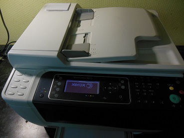
Сервисный центр Комплэйс выполняет Ремонт Xerox WC 6015
Замятие бумаги WC 6015
МФУ Xerox WC 6015 поступило в ремонт с постоянным сообщением о замятии бумаги, бумаги не было нигде.
После разборки аппарата подбираемся к датчику бумаги. Сам датчик прохождения бумаги находится сзади, показан стрелкой.

Сломанный датчик заменяем. На этом ремонт МФУ Xerox закончен.
Второй датчик находится в узле закрепления.
Треск при работе WC 6015
Треск в узле ксерографии
В другом МФУ Xerox WC 6015 при включении и работе раздавался сильный треск. Пришлось разбирать МФУ еще дальше.
Сильный треск был вызван тем, что в синем цвете забился тракт отвода отработанного тонера. После тщательной очистки спрессованного тонера, который превратился в камень, треск исчез. Отработанный тонер стал уходить в картридж.
Треск Xerox WC 6015 в области печки
Треск в области печки означает проскальзывание шестерней. В Xerox WC 6015 такое вероятно, если сломалось крепление печки. При такой неисправности шестерня печки не прижимаются к шестерне редуктора принтера. Поэтому и происходит проскальзывание и сильный треск.
Печка в этом МФУ с задней стороны крепится двумя винтами. А снизу печка цепляется за основание с помощью железных полукруглых упоров.
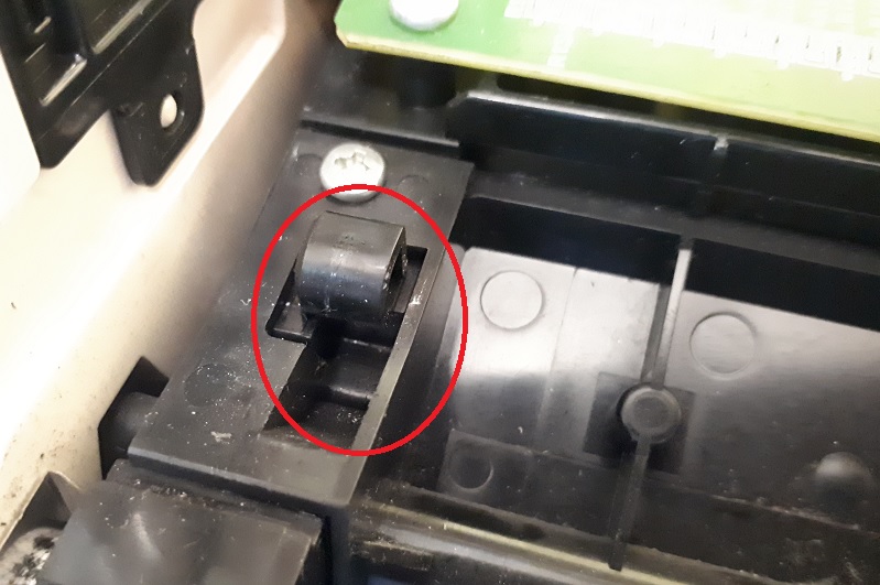
Если упор отсутствует печка не держится. В нашем случае полукруглый упор был отломан.
Ремонт выполнили следующим образом.
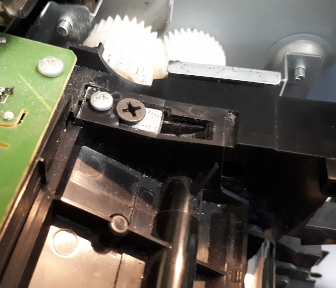
Стоимость ремонта крепления печки 3500 руб. Полукруг не обязателен.
Ошибка 024-360
Разберите по-новой весь принтер и проверьте разъемы на целостность и правильное соединение.Особенно тщательно проверьте контактные концы шлейфов. Если они повреждены, то отремонтируйте.
Ремонт контактной группы картриджей
Если у вас произошло повреждение контактной группы картриджа , то вряд ли найдете новую группу в продаже. Вообще для Xerox WC 6015 с запчастями проблема. Мы научились восстанавливать сломанные контакты. Но есть сложности — контактные группы никто не продает.
Для ремонта контакта нужно разобрать МФУ, вынуть контактную группу, починить сломанную контактную пластину.
Цена восстановления 2500 р.
Ошибка 092-651
Ошибка 092-651 с разными подкодами возникает, когда аппарат не может выполнить калибровку цветов. Эта калибровка осуществляется при включении принтера. Принтер выполняет калибровку путем нанесения на ленту переноса прямоугольных образцов всех 4 цветов по-очереди. Затем считывает плотность этих образцов датчиками CTD. Если плотность печати любого из цветов недостаточна или не изменяется, то выдается ошибка 092-651 с соответствующим подкодом и МФУ блокируется .
Расшифровку подкодов найти не удалось. Особенностью ошибки 092-651 является то, что после этой ошибки принтер не закачивает тонер из картриджей в блок ксерографии и, похоже, простого выхода из этой ситуации нет.
Первая причина ошибки 092-651 — это загрязненные датчики CTD, расположенные сзади принтера под лентой переноса. CTD — Color Toner Density Sensor. Т.е. это датчики плотности тонера для цветовой калибровке в каждом цветном лазерном принтере. Расположены они сзади под лентой переноса. Для решения этой проблемы протираем датчики спиртом и запускаем МФУ снова.
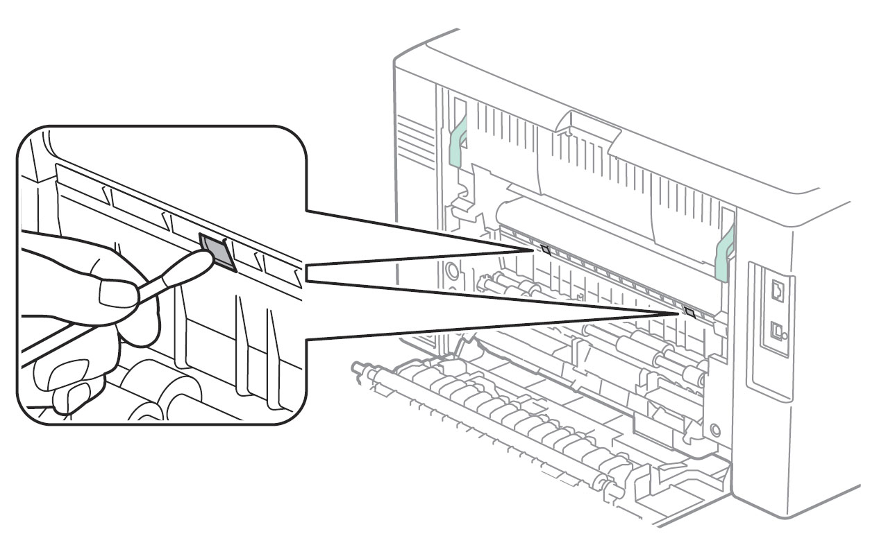
Если проблема не решается, переходим к следующей процедуре.
Вторая причина — в блоке ксерографии недостаточно девелопера, который переносит тонер. Этот вариант происходит, если заправлять картридж не подходящим тонером. Например, универсальным тонером Samsung. В этом случае девелопер уходит и принтер печатает бледно. Чтобы добавить девелопер в блок ксерографии, нужно разобрать весь МФУ. Мало кто выполнить эту работу меньше, чем за 5000 руб.
Третья причина — в блоке ксерогафии мало тонера какого-то цвета. Причиной может быть неисправный картридж. В нашем случае была ошибка 092-651 код 2440000. Причиной являлись дешевые китайские картриджи, в которых выходное отверстие было заклеено липкой бумагой. После удаления бумаги клей остался. После установки картриджей клей плотно приклеился к уплотнительной резинке принтера. Это вызыИногда из-завает перекрытие выходного отверстия для тонера.
Решение такое. Во время включения вручную принудительно закачивать тонер каждого цвета, пока тонер не появится в блоке ксерографии. Когда он появится, принтер оживет и станет самостоятельно подкачивать тонер. Цена работы 2500 руб.
Подкоды ошибки 092-651
Иногда из-за плохого тонера возникает ошибка 092-651 28f0000. При таком коде при калибровке совсем отсутствуют цвета желтый, красный, синий. Есть только черный.
Решение. Замена тонера в цветных картриджах. С помощью сервисного меню можно отдельно запустить двигатели каждого картриджа. Но не более 3 секунд на каждый.
После этого все цвета появятся, но может возникнуть ошибка 092-651 2880000. Это совсем плохо. Скорее всего, код означает, что яркости черного не хватает для калибровки. Значит в блоке ксерографии плохой тонер или недостаточно девелопера. Но за заправку девелопером мы не беремся. Слишком много геморроя.
WC 6015 не печатает с компьютера
Очень типичная ситуация. При подключении Xerox WC 6015 к компьютеру с Windows 7 драйверы устанавливаются автоматически через обновления Windows. Далее пробуете что-нибудь напечатать и ничего не происходит — задания на печать уходят в никуда, даже ошибки не появляется.
Виной всему неправильный драйвер для Windows 7, а, возможно, и для Windows 8 и 10.
Решение: скачайте и установите драйвер с официального сайта Xerox (весит около 200Мб). После установки оригинального драйвера принтер Xerox WC 6015, который ранее не печатал от компьютера, стал печатать под Windows 7 и Windows 10.
Цены на ремонт WC 6015
Ремонт подачи бумаги (застревание) 2500-3000 руб.
Треск — ремонт узла ксерографии — от 3000 руб.
Ремонт контактной группы 2500 руб.
Ремонт крепления печки 3500 руб.
Ремонт WorkCentre 6015 начинается с разборки.
Разборка WC 6015
Сначала нужно снять сканер, для этого снимаем декоративную переднюю синюю крышку, которая крепится на защелках.
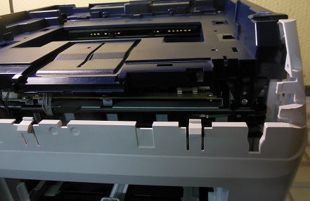
Затем снимаем боковую левую крышку.
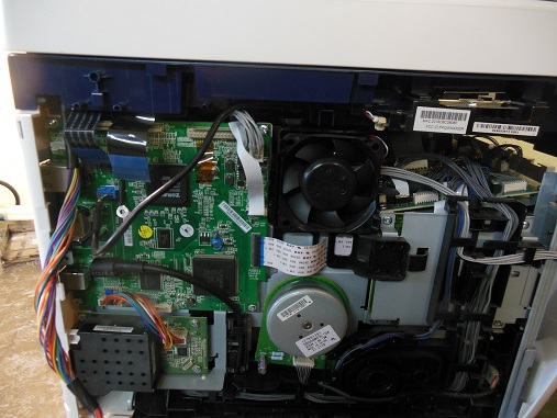
Отсоединяем шлейфы и кабели, откручиваем спереди держатели лифта сканера, снимаем сканер вверх. Затем откручиваем сверху винты и снимаем верхнюю крышку.
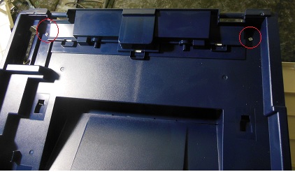
Снимаем заднюю крышку принтера.
Снимаем правую боковую крышку с картриджами.
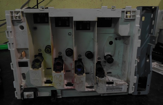
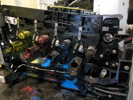
Следует отметить, что разборка Xerox WC 6015 — чрезвычайно трудоемкое дело. Спроектировано МФУ крайне неудачно для ремонта, требует большой концентрации, аккуратности и времени. За полную удачную разборку и сборку аппарата Xerox WC 6015 можно смело давать звание героя России.
Наверху принтера расположены 3 платы.
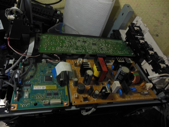
Чтобы добраться до узла ксерографии, нужно снять их все.
После этого нужно снять все боковые платы!, чтобы открутить 2 винта, крепящие верхнюю крышку сбоку.
На последнем этапе снимаем плату MCU, за которой и находятся 2 винта.
Если после обратной сборки неправильно соединили какой-нибудь разъем, то при инициализации появится критическая ошибка 024-360. Диагностика тупая — разъем любой, но вероятнее всего шлейф.
Источник