Ремонт блока управления компрессора >
Регулятор Elektronikon выполняет следующие функции
• управление компрессором;
• защита компрессора;
• контроль компонентов, подлежащих техническому обслуживанию;
• автоматический перезапуск после отказа электроснабжения (эта функция выключена).
Автоматическое управление компрессором
Регулятор поддерживает давление в сети так, чтобы оно находилось между заранее запрограммированными предельными значениями. Управление производится путем автоматической нагрузки и разгрузки компрессора. При этом принимается во
внимание ряд заранее запрограммированных настроек (уставок), например, давления разгрузки и нагрузки, минимальное время останова и максимальное количество пусков электродвигателя.
С целью снижения энергопотребления регулятор останавливает компрессор во всех случаях, когда это возможно, а затем, когда давление в сети падает, автоматически производит повторный пуск.
Защита компрессора

Защитный останов
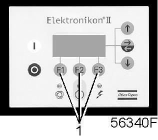
Если температура на выходе компрессорного элемента превысит запрограммированное значение уровня защитного останова, компрессор будет остановлен. Это отобразится на дисплее (1). Компрессор будет также остановлен в случае перегрузки приводного двигателя.
Компрессоры с воздушным охлаждением будут также остановлены в случае перегрузки двигателя вентилятора.
 |
Перед проведением ремонта изучите раздел «Техника безопасности». |
Ни в коем случае не пытайтесь самостоятельно ликвидировать неполадки. Это может усугубить ситуацию и спровоцировать аварии. Специалисты сервисной службы БВА приедут на объект в любое время дня и ночи и оперативно устранят сбои, не нанося ущерба производственному процессу. Всегда в наличии оригинальные запчасти и расходники.
Предупреждение о защитном останове
Уровень предупреждения о защитном останове представляет собой программируемый уровень, устанавливаемые ниже уровня защитного останова.
Если один из измеряемых параметров превысит запрограммированный уровень предупреждения о защитном останове, то это также отобразится на дисплее, предупреждая оператора перед тем, как будет достигнут уровень защитного останова.
Предупреждение о необходимости технического обслуживания
Если таймер технического обслуживания превышает запрограммированное значение, это указывается на экране дисплея (1), чтобы предупредить оператора о необходимости выполнения операций технического обслуживания.
Автоматический перезапуск после отказа электроснабжения
В регуляторе имеется встроенная функция автоматического перезапуска компрессора, когда напряжение питания восстанавливается после отказа электроснабжения. При отгрузке с предприятия-изготовителя данная функция не активизирована. При необходимости ее можно активизировать. Обратитесь за консультацией в сервисный центр.
|
Если функция активизирована и при условии, что блок находится в режиме автоматического управления, компрессор будет автоматически перезапускаться, если подача напряжения питания регулятора возобновится в течение запрограммированного промежутка времени. |
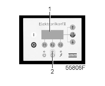
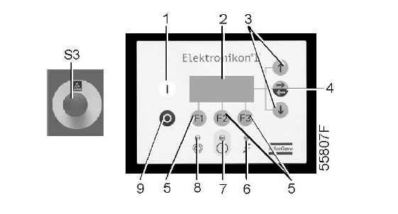
Регулятор Elektronikon I

| Позиция | Наименование | Назначение |
| S3 | Кнопка аварийного останова | Кнопка для немедленной остановки компрессора в случае аварийной ситуации. После устранения неисправности разблокируйте кнопку, вытянув ее из панели, и нажмите клавишу сброса (4). |
| 1 | Кнопка «Останов» (Stop) | Нажатие кнопки приводит к остановке компрессора. Светодиод (10) гаснет. Компрессор остановится после того, как он проработает в разгруженном режиме в течение примерно 30 с. |
| 2 | Кнопка «Пуск» (Start) | Кнопка для пуска компрессора. Загорается светодиод (10), показывая, что регулятор Elektronikon работает (в режиме автоматического управления). |
| 3 | Дисплей | Показывает состояние работы компрессора, текущие измеряемые значения и запрограммированные параметры. |
| 4 | Клавиша сброса | Клавиша для сброса таймера технического обслуживания, состояния защитного останова и т. д. |
| 5 | Клавиша ввода | Клавиша для выбора или подтверждения параметра, открытия вспомогательного окна или возврата в предыдущее окно. |
| 6 | Светодиод «Напряжение включено» (Voltage on) | Показывает, что напряжение включено. |
| 7 | Пиктограмма | Напряжение включено |
| 8 | Светодиод «Общий аварийный сигнал» (General alarm) | Горит, если существуют условия для предупреждения. |
| 8 | Светодиод «Общий аварийный сигнал» (General alarm) | Мигает, если компрессор находится в состоянии защитного или аварийного останова. |
| 9 | Пиктограмма | Аварийный сигнал |
| 10 | Светодиод «Автомати- ческое управление» (Automatic operation) | Показывает, что регулятор находится в режиме автоматического управления компрессором: компрессор нагружается, разгружается, останавливается и вновь запускается в зависимости от потребления сжатого воздуха и ограничений, запрограммированных в регуляторе. |
| 11 | Пиктограмма | Автоматическое управление |
| 12 | Клавиша прокрутки вниз | Клавиша для «прокручивания» вниз окон на дисплее или уменьшения уставки. |
| 13 | Клавиша прокрутки вверх | Клавиша для «прокручивания» вверх окон на дисплее или увеличения уставки. |
Дисплей
Обычно дисплей (1) показывает:
• состояние компрессора с помощью пиктограмм;
• давление сжатого воздуха на выходе компрессора;
• текущую температуру на выходе компрессорного элемента;
• текущую температуру точки росы для компрессоров полнофункциональной модификации.
Дисплей также показывает все измеряемые и запрограммированные параметры, см. раздел «Прокручивание всех окон дисплея».
Пиктограммы, используемые на экране
| Пиктограмма | Объяснение |
 |
Состояние компрессора «НАГРУЖЕН» (во время работы под нагрузкой горизонтальная стрелка мигает). |
 |
Состояние компрессора «РАЗГРУЖЕН» |
 |
Наработка компрессора |
 |
Температура на выходе компрессорного элемента. |
 |
Температура точки росы. |
 |
Приводной двигатель или двигатель вентилятора перегружен. |
 |
Нажата кнопка аварийного останова. |
Предупреждение о защитном останове
Предупреждение о защитном останове появится в случае:
• слишком высокой температуры воздуха на выходе компрессорного элемента,
• слишком высокой температуры точки росы для компрессоров полнофункциональной модификации.
Температура воздуха на выходе компрессорного элемента

- Если температура воздуха на выходе компрессорного элемента превысит уровень предупреждения о защитном останове (110 °С / 230 °F, не программируется), загорится светодиод аварийной сигнализации (4) и появится соответствующая мигающая пиктограмма.
Окно предупреждения о температуре на выходе компрессорного элемента
|
|
|
|
|
мигает |
||
|
bar(бар) 6,6 |

- Нажмите клавишу со стрелкой (3), появляется надпись < r000 > (регистр 000).
- Нажмите клавишу со стрелкой (3), появляется текущая температура на выходе компрессорного элемента.
Окно предупреждения о температуре на выходе компрессорного элемента
|
|
||
|
мигает |
||
|
°С 111 |
Окно показывает, что температура на выходе компрессорного элемента составляет 111 °С.
- Можно прокрутить на экране другие окна (используя клавиши 3 и 5), чтобы проверьте текущие состояния других параметров.
- Нажмите клавишу (1), чтобы остановить компрессор и дождитесь останова компрессора.
- Выключите напряжение, осмотрите компрессор и устраните неисправность.
- Предупреждающее сообщение исчезнет, как только исчезнут условия для его появления.
Температура точки росы
Для компрессоров со встроенным осушителем:
- Если температура точки росы превысит уровень предупреждения о защитном останове (программируется), загорится светодиод аварийной сигнализации (4) и появится соответствующая мигающая пиктограмма.
Окно предупреждения о температуре точки росы
 |
|
|
|
мигает |
||
|
bar(бар) 6,6 |

- Нажмите клавишу со стрелкой (3), появляется надпись < r000 > (регистр 000).
- Нажмите клавишу со стрелкой (3), появляется текущая температура точки росы.
Окно предупреждения о температуре на выходе компрессорного элемента
|
|
||
|
мигает |
||
|
°С 9 |
Окно показывает, что температура точки росы составляет 9 °С.
- Можно прокрутить на экране другие окна (используя клавиши 3 и 5), чтобы проверьте текущие состояния других параметров.
- Нажмите клавишу (1), чтобы остановить компрессор и дождитесь останова компрессора.
- Выключите напряжение, осмотрите компрессор и устраните неисправность.
- Предупреждающее сообщение исчезнет, как только исчезнут условия для его появления.
Защитный останов
Защитный останов компрессора произойдет в случае:
• если температура воздуха на выходе компрессорного элемента превысит уровень защитного останова;
• ошибки датчика давления на выходе компрессора;
• перегрузки приводного двигателя;
• перегрузки двигателя вентилятора в компрессорах с воздушным охлаждением.
Если температура воздуха на выходе компрессорного элемента превысит уровень защитного останова (120 °С / 248 °F, не программируется), произойдет защитный останов компрессора, будет мигать светодиод аварийной сигнализации (4), погаснет светодиод автоматического управления (5) и появится следующее окно:
Окно защитного останова по температуре на выходе компрессорного элемента
|
|
||
|
мигает |
- Нажмите клавишу со стрелкой (2), появляется надпись < r000 > (регистр 000).
- Нажмите клавишу со стрелкой (3), появляется текущая температура на выходе компрессорного элемента.
Окно защитного останова по температуре на выходе компрессорного элемента
|
|
||
|
мигает |
||
|
°С 122 |
Окно показывает, что температура на выходе компрессорного элемента составляет 122 °С.
- Выключите напряжение и устраните неисправность.
- После устранения неисправности, и когда исчезнут условия для защитного останова, включите напряжение и вновь запустите компрессор.
Перегрузка двигателя
- В случае перегрузки двигателя произойдет защитный останов компрессора, будет мигать светодиод аварийной сигнализации (4), погаснет светодиод автоматического управления (5) и появится следующее окно:
Окно защитного останова по перегрузке двигателя
|
|
||
|
мигает |

- Выключите напряжение и устраните неисправность.
- После устранения неисправности, и когда исчезнет условие для защитного останова, включите напряжение и вновь запустите компрессор.
Неисправности и способы их устранения
В компрессорах, оснащенных регулятором Elektronikon I, если горит или мигает светодиод аварийного сигнала, см. раздел «Предупреждение о защитном останове».
|
— |
Состояние |
Неисправность |
Способ устранения |
|
Компрессор начинает работать, однако не нагружается по истечении времени задержки. |
Неисправен электромагнитный клапан |
Замените клапан. |
|
|
Впускной клапан залип в закрытом положении. |
Проверьте клапан. |
||
|
Утечка в шлангах тракта пневмоуправления. |
Замените негерметичные шланги. |
||
|
Утечка в клапане минимального давления (когда стравливается давление из сети). |
Проверьте клапан. |
|
— |
Состояние |
Неисправность |
Способ устранения |
|
Компрессор не разгружается, выходит воздух из предохранительного клапана. |
Неисправен электромагнитный клапан |
Замените клапан. |
|
|
Впускной клапан не закрывается. |
Проверьте клапан. |
|
— |
Состояние |
Неисправность |
Способ устранения |
|
Во время работы под нагрузкой из отделителя конденсата не сливается конденсат |
Засорен сливной шланг. |
Проверьте и, если нужно, исправьте. |
|
|
Неисправен поплавковый клапан. |
Снимите узел поплавкового клапана, очистите и проверьте. |
|
— |
Состояние |
Неисправность |
Способ устранения |
|
Производительность компрессора или давление ниже нормы. |
Потребление сжатого воздуха превышает производительность компрессора. |
Проверьте присоединенное пневматическое оборудование. |
|
|
Засорен элемент воздушного фильтра. |
Замените элемент фильтра. |
||
|
Неисправен электромагнитный клапан. |
Замените клапан. |
||
|
Утечка в шлангах тракта пневмоуправления. |
Замените негерметичные шланги. |
||
|
Впускной клапан не полностью открыт. |
Проверьте клапан. |
||
|
Засорен маслоотделитель. |
Замените элемент. |
||
|
Утечка воздуха. |
Устраните утечку. |
||
|
Утечка из предохранительного клапана. |
Замените клапан. |
||
|
Неисправен компрессорный элемент. |
Проконсультируйтесь в сервисном центре. |
|
— |
Состояние |
Неисправность |
Способ устранения |
|
Чрезмерный расход масла; в компрессорах с GA5 по GA30C масло выносится в выпускной трубопровод сжатого воздуха |
Слишком высокий уровень масла. |
Проверьте на отсутствие переполнения. Стравите давление и слейте масло до правильного уровня. |
|
|
Неправильный тип масла вызывает пенообразование. |
Замените маслом правильного типа. |
||
|
Неисправен маслоотделитель. |
Проверьте элемент маслоотделителя. Если нужно, замените |
|
— |
Состояние |
Неисправность |
Способ устранения |
|
Предохранительный клапан выпускает воздух после| нагрузки. |
Неправильно работает впускной клапан. |
Проверьте клапан. |
|
|
Неправильно работает клапан минимального давления. |
Проверьте клапан. |
||
|
Неисправен предохранительный клапан. |
Замените клапан. |
||
|
Неисправен компрессорный элемент. |
Проконсультируйтесь в сервисном центре. |
||
|
Засорен элемент маслоотделителя. |
Замените элемент. |
|
— |
Состояние |
Неисправность |
Способ устранения |
|
Температура на выходе компрессорного элемента или на выходе компрессора выше нормы. |
Слишком низкий уровень масла. |
Проверьте и исправьте. |
|
|
В компрессорах с воздушным охлаждением недостаточная подача охлаждающего воздуха или слишком высокая температура охлаждающего воздуха. |
Убедитесь в отсутствии препятствий на пути подачи охлаждающего воздуха, либо улучшите вентиляцию в компрессорном зале. Избегайте рециркуляции охлаждающего воздуха. Если в компрессорном зале установлен вентилятор, проверьте его производительность. |
||
|
Засорен маслоохладитель. |
Очистите охладитель. |
||
|
Неисправен байпасный клапан. |
Проверьте клапан. |
||
|
Засорен воздухоохладитель. |
Очистите охладитель. |
||
|
Неисправен компрессорный элемент. |
Проконсультируйтесь в сервисном центре. |


Atlas Copco Elektronikon II MkIV


Ceccato ES3000


Ceccato ES4000 mini


Выключение
Описание
Компрессор будет остановлен:
- Если температура на выходе компрессорного элемента превысит уровень аварийного
останова (определяется датчиком температуры (TT11) или реле температуры
(TSHH11)).
- В случае ошибки датчика давления на выходе (PT20) или датчика температуры
(TT11).
- В случае перегрузки электродвигателя компрессора (M1).
Температура воздуха на выходе компрессорного элемента
Если температура на выходе компрессорного элемента превышает уровень аварийного
останова (задан на заводе-производителе, 115 ˚C/239 ˚F):
- Компрессор будет остановлен.
- Светодиод аварийной сигнализации (5) будет мигать.
- Появится следующий экран:

- Соответствующий значок мигает.

- Прокручивайте с помощью кнопок со стрелками вверх или вниз (4-8), пока не отобразится текущая температура на выходе компрессорного элемента.

На экране отображается значение температуры на выходе компрессорного элемента —
117 ˚C.
- Устранив причину аварийного отключения, нажмите кнопку ввода (7) на 5 секунд.
- Когда на экране появляется <rSt>, компрессор может быть перезапущен.
Перегрузка двигателя
В случае перегрузки двигателя:
- Компрессор будет остановлен.
- Светодиод аварийной сигнализации (5) будет мигать.
- Появится следующий экран:

Основной экран с индикацией аварийного отключения вследствие перегрузки двигателя
- Свяжитесь с поставщиком для выполнения поиска и устранения неисправностей
- Устранив причину аварийного отключения, нажмите кнопку ввода (7) на 5 секунд.
- Когда на экране появляется <rSt>, компрессор может быть перезапущен.
Ошибка датчика давления/температуры
В случае ошибки датчика давления на выходе (PT20) или датчика температуры (TT11):
- Компрессор будет остановлен.
- Появится следующий экран:

Контроллер Elektronikon™ Swipe


Контроллер Elektronikon™ Touch


Ошибки винтового компрессора
НЕИСПРАВНОСТЬ: Срабатывает прерыватель цепи защиты от перегрузки
Причина: 1. Низкое напряжение в сети.
Способ устранения: Проверьте напряжение в сети, нажмите кнопку сброса и перезапустите компрессор.
Причина: 2. Перегревается двигатель.
Способ устранения: Проверьте теплоотвод от двигателя и установку реле. Если тепло отводится нормально, нажмите кнопку «Reset» и перезапустите компрессор. Если компрессор не перезапускается сразу, подождите несколько минут и повторите попытку.
НЕИСПРАВНОСТЬ: Термостат отключает компрессор в результате перегрева.
Причина: 1. Очень высокая температура окружающей среды.
Способ устранения: Обеспечьте более качественную вентиляцию, нажмите сброс и сделайте перезапуск.
Причина: 2. Засорен охладитель масла.
Способ устранения: Очистите охладитель растворителем.
Причина: 3. Низкий уровень масла.
Способ устранения: Долейте масло.
Причина: 4. Неисправен термо-расширительный клапан.
Способ устранения: Замените термо-расширительный клапан.
НЕИСПРАВНОСТЬ: Высокий расход масла.
Причина: 1. Неисправна системы слива.
Способ устранения: Проверьте трубопроводы слива масла и обратный клапан.
Причина: 2. Чрезмерный уровень масла.
Способ устранения: Проверьте уровень масла, и при необходимости слейте лишнее.
Причина: 3. Неисправен фильтр маслосепаратора.
Способ устранения: Замените фильтр маслосепаратора.
Причина: 4. Не герметичность уплотнений и/или ниппелей фильтра маслосепаратора.
Способ устранения: Замените уплотнитель.
НЕИСПРАВНОСТЬ: Утечки масла из всасывающего фильтра.
Причина: Не закрыт регулятор всасывания.
Способ устранения: Проверьте регулятор и электромагнитный клапан.
НЕИСПРАВНОСТЬ: Открывается предохранительный клапан.
Причина: 1. Чрезмерно высокое давление.
Способ устранения: Проверьте настройки манометра. Проверьте регулятор всасывания и электромагнитный клапан.
Причина: 2. Регулятор всасывания не закрывается в конце рабочего цикла.
Способ устранения: Проверьте перепад давления между магистральным трубопроводом и резервуаром масляного сепаратора, при необходимости замените фильтр маслосепаратора.
Причина: 3. Засорение фильтра маслосепаратора
Способ устранения: Проверьте перепад давления между магистралью сжатого воздуха и резервуаром маслосепаратора, при необходимости замените фильтр маслосепаратора.
НЕИСПРАВНОСТЬ: Низкая производительность компрессора.
Причина: Загрязнение воздушного фильтра.
Способ устранения: Очистите/замените фильтр.
НЕИСПРАВНОСТЬ: Компрессор не выдает сжатый воздух.
Причина: 1. Закрыт регулятор, не открывается по причине загрязнения.
Способ устранения: Снять всасывающий фильтр и открыть регулятор вручную. При необходимости снять его и очистить.
Причина: 2. Закрыт регулятор, не открывается по причине отсутствия команды на открывание.
Способ устранения: Убедитесь, что реле давления подает питание на электромагнитный клапан, закрывающий данный патрубок.
НЕИСПРАВНОСТЬ: Давление вырабатываемого воздуха значительно превышает установленное максимальное (8, 10 или 13 бар)
Причина: 1. Открыт регулятор, не закрывается по причине загрязнения.
Способ устранения: Снимите и очистите регулятор.
Причина: 2. Открыт регулятор, не закрывается по причине отсутствия команды на закрывание.
Способ устранения: Убедитесь, что электромагнитный клапан, открывающий данный патрубок, отключен.
Причина: 3. Неисправен манометр.
Способ устранения: Проверьте работу и установки реле давления.
НЕИСПРАВНОСТЬ: Компрессор не перезапускается
Причина: Ненадлежащее закрывание контрольного клапана.
Способ устранения: Снимите и очистите клапан. При необходимости замените его компоненты.
НЕИСПРАВНОСТЬ: Компрессор не всегда включается
Причина: 1. Недостаточное напряжение в сети.
Способ устранения: Проверьте напряжение в сети.
Причина: 2. Слишком низкая температура воздуха.
Способ устранения: Нагрейте воздух в помещении или компрессор.
НЕИСПРАВНОСТЬ: Попадание масла в пульт управления
Причина: 1. Утечка масла из трубопровода.
Способ устранения: Затянуть соединительные муфты. Заменить поврежденные части трубопроводы.
Причина: 2. Утечка масла через передний фланец компрессора.
Способ устранения: Замените уплотнительное кольцо компрессора.
Источник
Индикация ошибок на блоке управления Atlas Copco Elektronikon II
Регулятор Elektronikon выполняет следующие функции
• управление компрессором;
• защита компрессора;
• контроль компонентов, подлежащих техническому обслуживанию;
• автоматический перезапуск после отказа электроснабжения (эта функция выключена).
Автоматическое управление компрессором
Регулятор поддерживает давление в сети так, чтобы оно находилось между заранее запрограммированными предельными значениями. Управление производится путем автоматической нагрузки и разгрузки компрессора. При этом принимается во
внимание ряд заранее запрограммированных настроек (уставок), например, давления разгрузки и нагрузки, минимальное время останова и максимальное количество пусков электродвигателя.
С целью снижения энергопотребления регулятор останавливает компрессор во всех случаях, когда это возможно, а затем, когда давление в сети падает, автоматически производит повторный пуск.
Защита компрессора
Защитный останов
Если температура на выходе компрессорного элемента превысит запрограммированное значение уровня защитного останова, компрессор будет остановлен. Это отобразится на дисплее (1). Компрессор будет также остановлен в случае перегрузки приводного двигателя.
Компрессоры с воздушным охлаждением будут также остановлены в случае перегрузки двигателя вентилятора.
 |
Перед проведением ремонта изучите раздел «Техника безопасности». |
Ни в коем случае не пытайтесь самостоятельно ликвидировать неполадки. Это может усугубить ситуацию и спровоцировать аварии. Специалисты сервисной службы БВА приедут на объект в любое время дня и ночи и оперативно устранят сбои, не нанося ущерба производственному процессу. Всегда в наличии оригинальные запчасти и расходники.
Предупреждение о защитном останове
Уровень предупреждения о защитном останове представляет собой программируемый уровень, устанавливаемые ниже уровня защитного останова.
Если один из измеряемых параметров превысит запрограммированный уровень предупреждения о защитном останове, то это также отобразится на дисплее, предупреждая оператора перед тем, как будет достигнут уровень защитного останова.
Предупреждение о необходимости технического обслуживания
Если таймер технического обслуживания превышает запрограммированное значение, это указывается на экране дисплея (1), чтобы предупредить оператора о необходимости выполнения операций технического обслуживания.
Автоматический перезапуск после отказа электроснабжения
В регуляторе имеется встроенная функция автоматического перезапуска компрессора, когда напряжение питания восстанавливается после отказа электроснабжения. При отгрузке с предприятия-изготовителя данная функция не
активизирована. При необходимости ее можно активизировать. Обратитесь за консультацией в сервисный центр.
|
Если функция активизирована и при условии, что блок находится в режиме автоматического управления, компрессор будет автоматически перезапускаться, если подача напряжения питания регулятора возобновится в течение запрограммированного промежутка времени. |
Регулятор Elektronikon II
| Позиция | Объяснение | Назначение |
| 1 | Кнопка «Пуск» (Start) | Кнопка для пуска компрессора. Загорается светодиод (8), показывая, что регулятор Elektronikon работает. |
| 2 | Дисплей | Показывает сообщения, относящиеся к эксплуатационным параметрам компрессора, необходимости технического обслуживания или неисправности. |
| 3 | Клавиши прокрутки | Клавиши для «прокручивания» вверх или вниз информации на экране дисплея. |
| 4 | Клавиша табулятора | Клавиша для выбора параметра, на который указывает горизонтальная стрелка. Можно изменять только параметры, сопровождаемые направленной вправо горизонтальной стрелкой. |
| 5 | Функциональные клавиши | Клавиши для управления компрессором и его программирования. |
| 6 | Светодиод «Напряжение включено» (Voltage on) | Показывает, что напряжение включено. |
| 7 | Светодиод «Общий аварийный сигнал» (General alarm) | Загорается в случае предупреждения о неисправности, необходимости сервисного обслуживания или отключении компрессора. |
| 7 | Светодиод «Общий аварийный сигнал» (General alarm) | Мигает, если существуют условия для защитного останова, если неисправен важный датчик или после аварийного останова. |
| 8 | Светодиод «Автомати‧ческое управление» (Automatic operation) | Показывает, что регулятор находится в режиме автоматического управления компрессором. |
| 9 | Кнопка «Останов» (Stop) | Нажатие кнопки приводит к остановке компрессора. Светодиодный индикатор (8) гаснет. Компрессор остановится после того, как он проработает в разгруженном режиме в течение примерно 30 с. |
| S3 | Кнопка аварийного останова | Кнопка для немедленной остановки компрессора в случае аварийной ситуации. После устранения неисправности разблокируйте кнопку, вытянув ее из панели. Предупреждение: В аварийных случаях используйте только S3! В нормальном режиме используйте кнопку Stop (Стоп) (9). |
Панель управления
Функциональные клавиши
Клавиши (1) используются:
• для нагрузки/разгрузки компрессора вручную;
• для вызова или программирования уставок;
• для сброса включившейся защиты двигателя от перегрузки, сообщения о защитном останове, сообщения о необходимости технического обслуживания, или аварийного останова;
• для доступа ко всем накопленным в регуляторе данным.
Функции клавиш изменяются в зависимости от отображаемого меню. Текущая функция отображается в нижней строке дисплея непосредственно над соответствующей клавишей. Наиболее часто употребляемые функции перечислены ниже:
| Обозначение | Назначение |
| «Add (Добавить)» | Добавить команды пуска/останова компрессора (день недели/час). |
| «Back (Назад)» | Возвратиться к опции или меню, находившимся на экране ранее. |
| ‘Canc’ (Отменить) | Отменить запрограммированную уставку при программировании параметров |
| «Удалить» (‘Del.’) | Стереть команды пуска/останова компрессора. |
| «Help (Помощь)» | Найти адрес компании Atlas Copco в интернете |
| «Lim (Ограничения)» | Показать предельные значения программируемой уставки |
| «Load (Нагрузить)» | Нагрузить компрессор вручную. |
| «Main (Основное окно)» | Возвратиться из меню в основное окно. |
| «Menu (Меню)» | Если кнопка нажимается в то время, когда на экран дисплея выведено основное окно, открывается доступ к подменю. |
| «Menu (Меню)» | Если кнопка нажимается в то время, когда на экран дисплея выведено то или иное подменю, происходит возврат к предыдущему меню. |
| «Mod. (Изменить)» | Изменить программируемые уставки. |
| «Prog (Программир ование)» | Программировать измененные уставки. |
| «Rset (Сброс)» | Перезапустить таймер или сбросить сообщение. |
| «Rtrn (Возврат)» | Возвратиться к опции или меню, находившимся на экране ранее. |
| «Unld (Разгрузить)» | Разгрузить компрессор вручную. |
| «Xtra (Дополнительно)» | Найти конфигурацию блоков регулятора. |
Предупреждение
Перед выполнением любых работ по техническому обслуживанию, ремонту и регулировке компрессора нажмите кнопку останова, подождите, пока компрессор не остановится (приблиз. 30 сек), затем закройте выпускной воздушный клапан. Нажимайте кнопку проверки в верхней части блока дренажа конденсата с электронным управлением до тех пор, пока полностью не сбросится давление из воздушной системы между воздушным ресивером и выпускным клапаном.
Нажмите кнопку аварийного останова и выключите напряжение.
Сбросьте из компрессора давление, отвернув заглушку маслоналивного отверстия на один оборот.
Разомкните и заблокируйте изолирующий выключатель.
Во время технического осмотра или ремонта выходной клапан воздуха может быть заблокирован следующим
образом:
• Закройте клапан.
• Удалите болт, фиксирующий рукоятку клапана, с помощью ключа, входящего в комплект поставки
компрессора.
• Поднимите рукоятку клапана и поворачивайте ее до тех пор, пока прорезь на рукоятке не совпадет с
фиксирующим краем клапана.
• Затяните болт.
Соблюдайте все необходимые Правила техники безопасности.
Источник
- Manuals
- Brands
- Atlas Copco Manuals
- Air Compressor
- GA 37 VSD
- Instruction book
-
Contents
-
Table of Contents
-
Bookmarks
Quick Links
INSTRUCTION BOOK
API480496
GA 37 VSD
Related Manuals for Atlas Copco GA 37 VSD
Summary of Contents for Atlas Copco GA 37 VSD
-
Page 1
INSTRUCTION BOOK API480496 GA 37 VSD… -
Page 3
Atlas Copco GA 37 VSD API480496 Instruction book Original instructions COPYRIGHT NOTICE Any unauthorized use or copying of the contents or any part thereof is prohibited. This applies in particular to trademarks, model denominations, part numbers and drawings. This instruction book is valid for CE as well as non-CE labelled machines. It meets the requirements for instructions specified by the applicable European directives as identified in the Declaration of Conformity. -
Page 4: Table Of Contents
Instruction book Table of contents Safety precautions………………….5 ……………………… 5 AFETY ICONS ………………….5 ENERAL SAFETY PRECAUTIONS ………………. 6 AFETY PRECAUTIONS DURING INSTALLATION ………………..7 AFETY PRECAUTIONS DURING OPERATION …………….8 AFETY PRECAUTIONS DURING MAINTENANCE OR REPAIR SMARTBOX…………10 PECIFIC SAFETY PRECAUTIONS FOR EQUIPMENT WITH General description………………….
-
Page 5
Instruction book 3.10 ……………………..42 ERVICE MENU 3.11 ……………………46 ODIFYING THE SETPOINT 3.12 ……………………48 VENT HISTORY MENU 3.13 ………………….49 ODIFYING GENERAL SETTINGS 3.14 ……………………….51 NFO MENU 3.15 ………………………52 EEK TIMER MENU 3.16 ……………………….. 61 EST MENU 3.17 ……………………62 SER PASSWORD MENU 3.18 …………………….. -
Page 6
Instruction book ……………………..97 RIVE MOTOR ……………………….98 IR FILTER …………………..98 IL AND OIL FILTER CHANGE ……………………….. 100 OOLERS ……………………..102 AFETY VALVES ………………..102 RYER MAINTENANCE INSTRUCTIONS ……………………..103 ERVICE KITS 7.10 ………………….103 TORAGE AFTER INSTALLATION 7.11 ………………….104 ISPOSAL OF USED MATERIAL Problem solving………………….105 Technical data………………….115 …………………… -
Page 7: Safety Precautions
Instruction book Safety precautions Safety icons Explanation Danger to life Warning Important note General safety precautions 1. The operator must employ safe working practices and observe all related work safety requirements and regulations. 2. If any of the following statements does not comply with the applicable legislation, the stricter of the two shall apply.
-
Page 8: Safety Precautions During Installation
Instruction book 9. If compressed air is used in the food industry and more specifically for direct food contact, it is recommended, for optimal safety, to use certified Class 0 compressors in combination with appropriate filtration depending on the application. Please contact your customer center for advice on specific filtration.
-
Page 9: Safety Precautions During Operation
Instruction book 12. The electrical connections must correspond to the applicable codes. The machines must be earthed and protected against short circuits by fuses in all phases. A lockable power isolating switch must be installed near the compressor. 13. On machines with automatic start/stop system or if the automatic restart function after voltage failure is activated, a sign stating «This machine may start without warning»…
-
Page 10: Safety Precautions During Maintenance Or Repair
Instruction book 6. Keep all bodywork doors shut during operation. The doors may be opened for short periods only, e.g. to carry out routine checks. Wear ear protectors when opening a door. On machines without bodywork, wear ear protection in the vicinity of the machine. 7.
-
Page 11
Instruction book 3. Use only genuine spare parts for maintenance or repair. The manufacturer will disclaim all damage or injuries caused by the use of non-genuine spare parts. 4. All maintenance work shall only be undertaken when the machine has cooled down. 5. -
Page 12: Specific Safety Precautions For Equipment With Smartbox
Instruction book Also consult following safety precautions: Safety precautions during installation Safety precautions during operation. These precautions apply to machinery processing or consuming air or inert gas. Processing of any other gas requires additional safety precautions typical to the application which are not included herein. Some precautions are general and cover several machine types and equipment;…
-
Page 13: General Description
Instruction book General description Introduction Introduction GA 37 VSD and GA 45 VSD are single-stage, oil-injected screw compressors driven by an electric motor. The compressors are enclosed in a sound-insulated bodywork and are available in air-cooled and water cooled version.
-
Page 14
Instruction book Front view, GA 37 VSD up to GA 45 VSD Workplace Full-Feature API480496… -
Page 15
Instruction book Rear view, GA 37 VSD up to GA 45 VSD Workplace Full-Feature Reference Name Air filter Air receiver Air outlet valve Air cooler Oil cooler CV/Vs Check valve/oil stop valve Automatic condensate outlet Automatic condensate outlet, dryer Dryer Compressor element Elektronikon™… -
Page 16: Air Flow
Instruction book Reference Name Electric cubicle Air flow Flow diagrams GA 37 VSD and GA 45 VSD Workplace Full-Feature Reference Description Air inlet Air/oil mixture Wet compressed air Condensate Dry compressed air (Full-Feature) API480496…
-
Page 17: Oil System
Instruction book Description Air drawn in through filter (AF) and check valve (CV) is compressed in compressor element (E). A mixture of compressed air and oil flows into the air receiver/oil separator (AR). The air is discharged through the outlet valve via minimum pressure valve (Vp), air cooler (Ca) and condensate trap (MT).
-
Page 18: Cooling System
Instruction book The oil system is provided with a thermostatic bypass valve (BV). When the oil temperature is below 40 ˚C (104 ˚F), the bypass valve shuts off the oil supply from oil cooler (Co). Air pressure forces the oil from air receiver (AR) through oil filter (OF) and oil stop valve (Vs) to compressor element (E).
-
Page 19: Condensate System
Instruction book Condensate system Drain connections Electronic condensate drains, typical example The compressors have an electronic water drain (EWD). The condensate formed in the air cooler accumulates in the collector. When the condensate reaches a certain level, it is discharged through the automatic drain outlet (Da).
-
Page 20
Instruction book Reference Designation Automatic drain connection Manual drain connection Automatic drain connection of the dryer (only on Full-Feature units) Manual drain connection of the dryer (only on Full-Feature units) Beside each automatic drain outlet is a manual (Dm) condensate drain connection for manually draining of the condensate. -
Page 21: Regulating System
Instruction book Green LED fading on/off Water is not flowing in to the drain‘s tank. If the floater does not reach the upper level for 3 hours, the solenoid is energized for 2 seconds. This cycle is repeated for 5 times (so up to 15 hours).
-
Page 22: Electrical System
Electrical system Electric components The electrical system comprises the frequency converter Neos (or Control Technics optional) with the following components: Electric cabinet for GA 37 VSD and GA 45 VSD, typical example Reference Designation Transformer Circuit breaker…
-
Page 23: Air Dryer
Instruction book Electrical diagrams 9820 6700 01 Service diagram GA30-45 VSD 9820 2175 00 The complete electrical diagram can be found in the electric cubicle. The complete electrical diagram can be found on the CD supplied with the machine. Air dryer (On compressors with integrated dryer only) Flow diagram Air dryer…
-
Page 24
Instruction book Reference Name Pressure switch, fan control Liquid separator Compressed air circuit Compressed air enters heat exchanger (1) and is cooled by the outgoing, cold, dried air. Water in the incoming air starts to condense. The air then flows through heat exchanger/evaporator (2), where the refrigerant evaporates, causing the air to be cooled further to close to the evaporating temperature of the refrigerant. -
Page 25: Elektronikon® Graphic Controller
Instruction book Elektronikon® Graphic controller ® Elektronikon Graphic controller Control panel ® Display of the Elektronikon Graphic controller Introduction The Elektronikon controller has following functions: • Controlling the compressor • Protecting the compressor • Monitoring components subject to service • Automatic restart after voltage failure (made inactive) Automatic control of the compressor operation The controller maintains the net pressure between programmable limits by automatically loading and unloading the compressor (on compressors running at a fixed speed) or by adapting the…
-
Page 26
For compressors leaving the factory, this function is made inactive. If desired, the function can be activated. Consult the Atlas Copco Customer Centre. If the function is activated and provided the regulator was in the automatic operation mode, the compressor will automatically restart if the supply voltage to the module is restored. -
Page 27: Control Panel
Instruction book Control panel Elektronikon regulator Control panel Parts and functions Reference Designation Function Display Shows the compressor operating condition and a number of icons to navigate through the menu. Pictograph Automatic operation Pictograph General alarm Alarm LED Flashes in case of a shut-down, is lit in case of a warning condition.
-
Page 28: Icons Used
Instruction book Icons used Status icons Name Icon Description Stopped / Running When the compressor is stopped, the icon stands still. When the compressor is running, the icon is rotating. Compressor status Motor stopped Running unloaded Running loaded Machine control mode Local start / stop Remote start / stop Network control…
-
Page 29
Instruction book Name Icon Description Active protection functions Emergency stop Shutdown Warning Service Service required Main screen display Value lines display icon Chart display icon General icons No communication / network problem Not valid Input icons Icon Description Pressure Temperature Digital input Special protection API480496… -
Page 30
Instruction book System icons Icon Description Compressor element (LP, HP, …) Dryer Frequency converter Drain Filter Motor Failure expansion module Network problem General alarm Menu icons Icon Description Inputs Outputs Alarms (Warnings, shutdowns) Counters API480496… -
Page 31
Instruction book Icon Description Test Settings Service Event history (saved data) Access key / User password Network Setpoint Info Navigation arrows Icon Description Down API480496… -
Page 32: Main Screen
Instruction book Main screen Control panel Scroll keys Enter key Escape key Function The Main screen is the screen that is shown automatically when the voltage is switched on and one of the keys is pushed. It is switched off automatically after a few minutes when no keys are pushed.
-
Page 33
Instruction book Typical Main screen (2 value lines) Text on figures Compressor Outlet Flow Load, shutdown, … (text varies upon the compressors actual condition) Menu Unload, ES,…(text varies upon the compressors actual condition) Typical Main screen (4 value lines) Text on figures Compressor Outlet Flow Off, Shutdown,… -
Page 34
Instruction book • Section B shows Status icons. Following icon types are shown in this field: • Fixed icons These icons are always shown in the main screen and cannot be selected by the cursor (e.g. Compressor stopped or running, Compressor status (running, running unloaded or motor stopped). -
Page 35
Instruction book The switch button (icon) for selecting other screens is changed into a small Chart and is highlighted (active). When the Chart (Medium Resolution) is selected, the chart shows the variation of the selected input per hour. The screen shows the last 4 hours. When the Chart (Low Resolution) is selected, the chart shows the variation of the selected input per day. -
Page 36: Calling Up Menus
Instruction book Calling up menus Control panel Control panel Scroll keys Enter key Escape key Description When the voltage is switched on, the main screen is shown automatically (see section Main screen): Typical Main screen (2 value lines) • To go to the Menu screen, select <Menu> (3), using the Scroll keys. •…
-
Page 37: Inputs Menu
Instruction book • The screen shows a number of icons. Each icon indicates a menu item. By default, the Pressure Settings (Regulation) icon is selected. The status bar shows the name of the menu that corresponds with the selected icon. •…
-
Page 38
Instruction book Text on image Inputs Compressor Outlet Element Outlet Ambient Air Emergency Stop • The screen shows a list of all inputs with their corresponding icons and readings. • If an input is in warning or shutdown, the original icon is replaced by the warning or shutdown icon respectively (i.c. -
Page 39: Outputs Menu
Instruction book Select Yes to remove or No to quit the current action. In a similar way, another input signal can be highlighted and selected as Main Chart signal: (1): Set as main chart signal Outputs menu Menu icon, Outputs Function To call up information regarding the actual status of some outputs such as the condition of the Fan overload contact (on air cooled compressors), the Emergency stop contact, etc.
-
Page 40
Instruction book Text on image Menu Regulation • Move the cursor to the Outputs icon (see above, section Menu icon, using the Scroll keys. • Press the Enter key. A screen similar to the one below appears: Outputs screen (typical) Text on image Outputs Fan motor… -
Page 41: Counters
Instruction book Counters Control panel Scroll keys Enter key Escape key Menu icon, Counters Function To call up: • The running hours • The loaded hours • The number of motor starts • The number of hours that the regulator has been powered •…
-
Page 42
Instruction book Text on figure Menu Regulation • Using the Scroll keys, move the cursor to the Counters icon (see above, section Menu icon) • Press the Enter key. Following screen appears: Text on figure Counters Running Hours Motor Starts Load Relay VSD 1-20 % rpm in % (the percentage of the time during which the motor speed was between 1 and 20 %) -
Page 43: Control Mode Selection
Instruction book Control mode selection Control panel Scroll keys Enter key Escape key Function To select the control mode, i.e. whether the compressor is in local control, remote control or controlled via a local area network (LAN). Procedure Starting from the main screen, make sure the button Menu (1) is selected: Next, use the scroll buttons to go to the regulation icon (2) and press the enter button: API480496…
-
Page 44: Service Menu
Instruction book There are 3 possibilities: • Local control • Remote control • LAN (network) control After selecting the required regulation mode, press the enter button on the controller to confirm your selection. The new setting is now visible on the main screen. See section Icons used for the meaning of the icons.
-
Page 45
Instruction book Text on image Menu Regulation • Using the Scroll keys, move the cursor to the Service icon (see above, section Menu icon). • Press the Enter key. Following screen appears: Text on image Service Overview Service Plan Next Service History •… -
Page 46
Instruction book The figures at the left are the programmed service intervals. For Service interval A, the programmed number of running hours is 4000 hours (upper row) and the programmed number of real time hours is 8760 hours, which corresponds to one year (second row). This means that the controller will launch a service warning when either 4000 running hours or 8760 real hours are reached, whichever comes first. -
Page 47
Instruction book Press the Enter key. Following screen appears: Modify the value as required using the ↑ or ↓ scroll key and press the Enter key to confirm. Note: Running hours and real time hours can be modified in steps of 100 hours. Next Service Text on image Next service… -
Page 48: Modifying The Setpoint
Instruction book Service level, Running hours or Real time hours), use the Scroll keys to select the desired action and press the Enter key. 3.11 Modifying the setpoint Control panel Scroll keys Enter key Escape key Menu icon, Setpoint Function On compressors with a frequency converter driven main motor, it is possible to program two different setpoints.
-
Page 49
Instruction book Text on image Menu Regulation • Activate the menu by pressing the enter key. A screen similar to the one below appears: Text on image Regulation Setpoint 1 Indirect stop level 1 Direct stop level 1 Setpoint 2 Modify •… -
Page 50: Event History Menu
Instruction book The upper and lower limit of the setting is shown in grey, the actual setting is shown in black. Use the ↑ or ↓ key of the Scroll keys to modify the settings as required and press the Enter key to accept.
-
Page 51: Modifying General Settings
Instruction book Text on image Menu Regulation • Using the Scroll keys, move the cursor to the Event History icon (see above, section Menu icon) • The list of last shutdown and emergency stop cases is shown. Example of Event History screen •…
-
Page 52
Instruction book Text on image Menu Regulation • Next, move the cursor to the Settings icon (see above, section menu icon), using the Scroll keys. • Press the Enter key. Following screen appears: This screen shows again a number of icons. By default, the User Password icon is selected. The status bar shows the description that corresponds with the selected icon. -
Page 53: Info Menu
• Move the cursor to the action button Menu and press the Enter key. Following screen appears: Text on image Menu Regulation • Using the Scroll keys, move the cursor to the Info icon (see above, section Menu icon). • Press the Enter key. The Atlas Copco internet address appears on the screen. API480496…
-
Page 54: Week Timer Menu
Instruction book 3.15 Week timer menu Control panel Scroll keys Enter key Escape key Menu icon, Week timer Function • To program time-based start/stop commands for the compressor • To program time-based change-over commands for the net pressure band • Four different week schemes can be programmed. •…
-
Page 55
Instruction book Text on figure Menu Week Timer • Press the Enter key on the controller. Following screen appears: Week Timer Week Action Schemes Week Cycle Status Week Timer Inactive Remaining Running Time The first item in this list is highlighted in red. Select the item requested and press the Enter key on the controller to modify. -
Page 56
Instruction book Week Action Schemes Week Action Scheme 1 Week Action Scheme 2 Week Action Scheme 3 Week Action Scheme 4 • A weekly list is shown. Monday is automatically selected and highlighted in red. Press the Enter key on the controller to set an action for this day. Week Action Scheme 1 Monday Tuesday… -
Page 57
Instruction book Monday Modify • A new pop-up window opens. Select an action from this list by using the Scroll keys on the controller. When ready press the Enter key to confirm. Monday Actions Remove Start Stop Pressure Setpoint 1 Modify •… -
Page 58
Instruction book Monday Start Save Modify • To adjust the time, use the Scroll keys on the controller and press the Enter key to confirm. Monday Start Save Modify • A pop-up window opens. Use the ↑ or ↓ key of Scroll keys to modify the values of the hours. Use the ←… -
Page 59
Instruction book Monday Start Save Modify • A new pop-up window opens. Use the Scroll keys on the controller to select the correct actions. Press the Enter key to confirm. Monday Are you sure? Save Modify Press the Escape key to leave this window. •… -
Page 60
Instruction book Monday — Start Tuesday Wednesday Thursday Friday Saturday Sunday Press the Escape key on the controller to leave this screen. Programming the week cycle A week cycle is a sequence of 10 weeks. For each week in the cycle, one of the four programmed week schemes can be chosen. -
Page 61
Instruction book Week 3 Week 4 Modify Press twice the Enter key on the controller to modify the first week. • A new window opens. Select the action, example: Week Action Scheme 1 Week Cycle Week 1 Week Action Scheme 1 Week Action Scheme 2 Week Action Scheme 3 Modify… -
Page 62
Instruction book Week Timer Week Week Timer Inactive Week 1 • Press the Escape key on the controller to leave this window. The status shows that week 1 is active. Week Timer Week Action Schemes Week Cycle Status Remaining Running Time •… -
Page 63: Test Menu
Instruction book Week Timer Week Action Schemes Week Cycle Status Remaining Running Time • This timer is used when the week timer is set and for certain reasons the compressor must continue working, for example, 1 hour, it can be set in this screen. This timer is prior to the Week Timer action.
-
Page 64: User Password Menu
Instruction book • Using the scroll keys (1), move the cursor to the test icon (see above, section Menu icon) • Press the enter key (2), following screen appears: Text on image Test Safety Valve Test Not allowed Audit Data •…
-
Page 65: Web Server
Instruction book • Using the Scroll keys, select the Settings icon (see section Modifying general settings) • Press the Enter key. Following screen appears: • Move the cursor to the Password icon (see above, section Menu icon) • Select <Modify> using the Scroll keys and press the Enter key. Next, modify the password as required.
-
Page 66
Instruction book • Click on Change adapter settings (1). • Select the Local Area Connection, which is connected to the controller. • Click with the right button and select Properties (1). • Use the check box Internet Protocol version +4 (TCP/IPv4) (1) (see picture). To avoid conflicts, uncheck other properties if they are checked. -
Page 67
Instruction book • Use the following settings: • IP Address 192.168.100.200 (1) • Subnetmask 255.255.255.0 (2) Click OK (3) and close network connections. Configure a company network (LAN) connection • Ask your IT department to generate a fixed IP address in your company’s network. •… -
Page 68
Instruction book • Adapt the network settings in the controller: • Go to Main Menu • Go to Settings (1) • Go to Network (1) API480496… -
Page 69
Instruction book • Go to Ethernet (1) • Switch Off (1) the Ethernet communication to allow editing the settings • Adapt IP Address (1) • Adapt Gateway IP (2) • Adapt Subnet Mask (3) • Switch On (4) the Ethernet communication API480496… -
Page 70
Instruction book • Wait a few minutes so the LAN network can connect to the controller Configuration of the web server ® The internal web server is designed and tested for Microsoft Internet Explorer. Also «Opera», «Mozilla Firefox», «Safari»and «Chrome» should work. Viewing the controller data All screen shots are indicative. -
Page 71
Instruction book Navigation and options • The banner shows the unit type and the language selector. In this example, three languages are available on the controller. • On the left side of the interface, you can find the navigation menu. If a license for ESi is foreseen, the menu contains 3 buttons. -
Page 72
Instruction book Info status Machine status is always shown on the web interface. Digital inputs Lists all digital inputs and their status. Digital outputs Lists all digital outputs and their status. Special protections Lists all special protections of the unit. Service plan Displays all levels of the service plan and their status. -
Page 73: Programmable Settings
Instruction book 3.19 Programmable settings Compressor/motor Minimum Factory Maximum setting setting setting Set-point 1 and 2, Workplace Full-Feature bar(e) 12.8 compressors Indirect stop level Direct stop level Proportional band Integration time Parameters Minimum Factory Maximum setting setting setting Minimum stop time Power recovery time 3600 Restart delay…
-
Page 74
The built-in service timers will give a Service warning message after their respective preprogrammed time interval has elapsed. For specific data, see section Preventive Maintenance. Consult Atlas Copco if a timer setting needs to be changed. The intervals must not exceed the nominal intervals and must coincide logically. See section Modifying general settings. -
Page 75: Smartbox And Smartlink
Instruction book SMARTBOX and SMARTLINK SMARTBOX The machine is equipped with a SMARTBOX mounted in the electrical cabinet. The SMARTBOX allows read-out of a number of parameters of the machine on a user login- protected web site called SMARTLINK. The connected antenna is mounted on the outside of the machine.
-
Page 76
Instruction book • You will receive an e-mail with login credentials. • Go to the SMARTLINK web site http://www.atlascopco.com/smartlink, log in with the user credentials. • Enjoy SMARTLINK! • In case more SMARTLINK-ready machines are available, you can add these via My Profile. API480496… -
Page 77: Installation
Dimension drawings The drawings are on the CD, supplied with your machine Dimension drawing Model 9820 9790 03 GA 37 VSD, GA 45 VSD Text on drawings Translation or Explanation Compressor cooling air outlet Cooling air outlet of compressor and motor…
-
Page 78: Installation Proposal
Instruction book Installation proposal Compressor room example Compressor room example Air cooling Water cooling The direction of the cooling flows may never be inverted Description Compressor Install the compressor unit on a solid, level floor, suitable for taking its weight. API480496…
-
Page 79
Instruction book Position of the compressed air outlet valve. The pressure drop over the air delivery pipe can be calculated from: 1.85 Δp = (L x 450 x Q ) / (d x P), with d = inner diameter of the pipe in mm Δp = pressure drop in bar (recommended maximum: 0.1 bar (1.5 psi)) L = length of the pipe in m P = absolute pressure at the compressor outlet in bar(a) -
Page 80
If frost might occur, the appropriate measures should be taken to avoid damage to the machine and its ancillary equipment. In this case, and also if operating above 1000 m (3300 ft), consult Atlas Copco. Moving/lifting The compressor can be moved by a lift truck using the slots in the frame. -
Page 81: Electrical Connections
Working with machinery controlled by a frequency converter requires special safety precautions. These safety precautions depend on the kind of network used (TN, TT, IT system). Consult Atlas Copco. Most compressors are designed for use in TT/TN networks and are intended for industrial environments where the electrical supply is separated from the residential/ commercial supply network.
-
Page 82
Instruction book Electrical connections for GA 37 VSD and GA 45 VSD Reference Designation Customer’s installation (Available as) option Compressor motor Note The complete electrical diagram can be found in the electrical cubicle. The complete electrical diagram can be found on the CD supplied with the machine. -
Page 83: Pictographs
Have the modifications checked by Atlas Copco. Stop the compressor and switch off the voltage before connecting external equipment. Only potential-free contacts are allowed. • LAN control: The compressor is controlled via a local network. Consult Atlas Copco. Pictographs Pictographs…
-
Page 84
Instruction book Reference Designation Warning: Always read the manual, switch off the voltage, depressurise compressor and lock out/ tag out before repairing. Keep the doors closed during operation API480496… -
Page 85
Instruction book Reference Designation Switch off the voltage before removing protecting cover inside electric cubicle Warning, voltage Automatic condensate drain Stop the compressor before cleaning the coolers Lightly oil the gasket of the oil filter, screw it on and tighten by hand (approx. half a turn) Before connecting the compressor electrically, consult the Instruction book for the motor rotation direction Compressor remains pressurized for 180 seconds after switching off the voltage… -
Page 86: Operating Instructions
• Bolts and bushes under the gear casing (2) • Supports under motor (3) Transport fixtures of GA 37 VSD and GA 45 VSD 3. Check that the electrical connections correspond to the local codes and that all wires are clamped tight to their terminals.
-
Page 87
For Full-Feature units: also connect the condensate drain outlet of the dryer to a drain collector. The drain pipes to the drain collector must not dip into the water. For draining of pure condensate water, install an oil/water separator which is available from Atlas Copco as an option. See section Introduction OSCi. -
Page 88
4. Reinstall the inlet hose. Make sure that all connections are tight. Position of arrestor on GA 37 VSD and GA 45 VSD 1. Check the oil level. The oil level should be between the oil filler neck (FC) and the top in the sight glass (Gl). -
Page 89: Before Starting
Instruction book 2. Switch on the voltage. On Full-Feature compressors: switch on the voltage and actuate contactor K12 (dryer fan) on the dryer rail for a few seconds (e.g. by means of a screw driver) to check for the rotation direction.
-
Page 90: During Operation
Instruction book Control panel Elektronikon™ Graphic Procedure 1. Open the air outlet valve. 2. Switch on the voltage. Check that voltage on LED lights up. 3. Press the start button on the control panel. The compressor starts running and the automatic operation LED lights up.
-
Page 91
Instruction book Regularly check the oil level. To do so: 1. Press the stop button on the control panel. 2. A few minutes after stopping, the oil level should be between the oil filler neck (FC) and the top of the sight glass (Gl). 3. -
Page 92: Checking The Display
Instruction book Air filter Position of the service indicator Regularly check the service indicator. If the colored part of service indicator (VI) shows full out, replace the air filter element. Reset the service indicator by pushing the knob in the extremity of the indicator body.
-
Page 93: Stopping
Instruction book service level for a monitored component has been exceeded. Carry out the service actions of the indicated plans or replace the component and reset the relevant timer, see section Service menu. Stopping Control panel Control panel Elektronikon™ Graphic Procedure Step Action…
-
Page 94
Instruction book Procedure Step Action Stop the compressor and close the air outlet valve. Press the test button on top of the electronic water drain(s) until the air system between air receiver and outlet valve is fully depressurized. Consult section Condensate system to locate the drain. -
Page 95: Maintenance
Instruction book Maintenance Preventive maintenance schedule Warning Control panel Always apply all relevant Safety precautions. Before carrying out any maintenance, repair work or adjustments, do as follows: • Stop the compressor. • Close the air outlet valve and press the test button on top of the electronic water drain(s) until the air system between air receiver and outlet valve is fully depressurized.
-
Page 96
Instruction book Service contracts Atlas Copco offers several types of service contracts, relieving you of all preventive maintenance work. Consult your Atlas Copco Customer Centre. General When servicing, replace all removed O-rings and washers. Intervals The local Atlas Copco Customer Centre may overrule the maintenance schedule, especially the service intervals, depending on the environmental and working conditions of the compressor. -
Page 97: Oil Specifications
In order to achieve the best machine performance and guarantee the reliability, it is required to use genuine Atlas Copco Lubricants. Their tailor made formulation is the result of years of field experience, research and in-house development. Consult the Spare Parts list for part number information.
-
Page 98
Extreme Roto-Inject Fluid NDURANCE Atlas Copco’s Roto-Inject Fluid NDURANCE is a premium mineral oil based 4000 hours lubricant, specially developed for use in single stage oil injected screw compressors running in mild conditions. Its specific formulation keeps the compressor in excellent condition. Roto-Inject Fluid NDURANCE can be used for compressors operating at ambient temperatures between 0 ˚C (32… -
Page 99: Drive Motor
Atlas Copco. Roto Synthetic Fluid XTEND DUTY Atlas Copco’s Roto Synthetic Fluid XTEND DUTY is a high quality synthetic 8000 hours lubricant for oil injected screw compressors which keeps the compressor in excellent condition. Because of its excellent oxidation stability, Roto Synthetic Fluid XTEND DUTY can be used for compressors operating at ambient temperatures between 0 ˚C (32 ˚F) and 46 ˚C (115 ˚F).
-
Page 100: Air Filter
Instruction book Air filter Location of air filter Recommendations 1. Never remove the element while the compressor is running. 2. For minimum downtime, replace the dirty element by a new one. 3. Discard the element when damaged. Procedure 1. Stop the compressor. Switch off the voltage. 2.
-
Page 101
Instruction book Procedure Oil drain and filler plug on the oil separator vessel Oil drain plugs, check valve and gear casing API480496… -
Page 102: Coolers
Instruction book Vent plug, oil cooler Step Description Run the compressor until warm. Stop the compressor after 3 minutes of unloaded operation. Close the air outlet valve and switch off the voltage. Wait a few minutes and depressurise by unscrewing oil filler plug (FC) just one turn to permit any pressure in the system to escape. Air cooled units: loosen the vent plug (VP) of the oil cooler and wait for 5 minutes.
-
Page 103
• Next, clean with an air jet in the reverse direction to normal flow. Use low pressure air. If necessary, the pressure may be increased up to 6 bar(e) (87 psig). • If it is necessary to wash the coolers with a cleaning agent, consult Atlas Copco. • Remove the cover used during cleaning. -
Page 104: Safety Valves
Instruction book Safety valves Location of safety valve Position of safety valve Operating Operate the safety valve from time to time by unscrewing the cap one or two turns. Retighten it afterwards. Testing Before removing the valve, depressurize the compressor. See also section Problem solving. The safety valve (SV) can be tested on a separate air line.
-
Page 105: Service Kits
Instruction book • Contact of refrigerant with the skin will cause freezing. Special gloves must be worn. If contacted with the skin, the skin should be rinsed with water. On no account may clothing be removed. • Fluid refrigerant will also cause freezing of the eyes; always wear safety glasses. •…
-
Page 106: Disposal Of Used Material
Instruction book If the compressor is going to be stored without running from time to time, protective measures must be taken. Consult your supplier. 7.11 Disposal of used material Used filters or any other used material (e.g. desiccant, lubricants, cleaning rags, machine parts, etc.) must be disposed of in an environmentally friendly and safe manner, and in line with the local recommendations and environmental legislation.
-
Page 107: Problem Solving
Instruction book Problem solving Warning Always apply all relevant Safety precautions. Before carrying out any maintenance, repair work or adjustment, press the stop button, wait until the compressor has stopped and close the air outlet valve. Open the manual drain valve(s). Press the emergency stop button and switch off the voltage.
-
Page 108
If installed, check capacity of compressor room fan Oil cooler clogged Clean cooler Thermostatic valve malfunctioning Have valve tested. Replace if necessary. Air cooler clogged Clean cooler Compressor element out of order Consult Atlas Copco Customer Centre API480496… -
Page 109
Instruction book Condition Possible cause Remedy Excessive oil consumption; oil Incorrect oil causing foam Change to correct oil carry-over through discharge line Oil level too high Check for overfilling. Release pressure and drain oil to correct level. Oil separator defective Replace oil separator element Malfunctioning of the scavenge Replace non-return valve in the… -
Page 110
Instruction book Condition Fault Remedy Condenser pressure too high See above or too low Shortage of refrigerant Have circuit checked for leaks and recharged if necessary Converter fault codes If a problem is detected by the converter, a specific code (Main motor converter alarm) will appear on the Elektronikon display, together with a fault code. -
Page 111
Instruction book Main Motor Converter Alarm Fault Below table lists the most important error codes. If another code appears, please contact Atlas Copco. Neos If a problem is detected by the Neos converter, a specific code (Main motor converter alarm) will appear on the Elektronikon display, together with a fault code and a fault description. -
Page 112
Short Circuit detected in U phase overcurrent 0x2316 Motor Short Circuit detected in V phase Try to reset the error. overcurrent If error returns, contact Atlas Copco. 0x2317 Motor Short Circuit detected in W phase overcurrent 0x3210 Overvoltage Overvoltage detected… -
Page 113
Instruction book Fault Fault Cause Actions code description 0x4311 Drive Overtemperature detected in an IGBT overtemperature 0x4312 Drive Overtemperature detected in the overtemperature heatsink 0x4314 Drive Overtemperature detected in IGBT overtemperature junction UH 0x4315 Drive Overtemperature detected in IGBT overtemperature junction UL 0x4316 Drive… -
Page 114
0x6103 Drive failure General fault detected (hardware) Try to reset the error. 0x6104 Drive failure Internal checksum error detected If error returns, contact Atlas Copco. (hardware) 0x6105 Drive failure Internal communication timeout (hardware) 0x6106 Drive failure Internal checksum error detected… -
Page 115
CAN cable. Both should be OFF. 0x6112 Drive failure Requested command cannot be Try to reset the error. (software) executed because of limited access If error returns, contact Atlas Copco. level 0x6113 Drive failure CAN communication overload Check CAN-cable connection (software) between Elektronikon and converter. -
Page 116
O.ht1 Converter overheating (IGBT) Check the ambient temperature. Check the cubicle cooling. Contact Atlas Copco. O.ht2 Converter overheating (heat sink) Check the ambient temperature. Check the cubicle cooling. Contact Atlas Copco. Motor overheating (thermistor) Check the ambient temperature. -
Page 117: Technical Data
Instruction book Technical data Readings on display Elektronikon™ Graphic controller Important The readings mentioned below are valid under the reference conditions (see section Reference conditions and limitations). Reference Reading Air outlet pressure Depends on the setpoint (desired net pressure). Compressor element Approx.
-
Page 118: Electric Cable Size And Fuses
I (1) Max fuse (1) I (2) Max fuse (2) HRC form HRC form GA 37 VSD 63.9 67.5 I: current in the supply lines at maximum load and nominal voltage (1): compressors without integrated dryer (2): compressors with integrated dryer…
-
Page 119
Instruction book Cable sizing according UL/cUL Calculation method according UL 508A, table 28.1 column 5: allowable current of insulated copper conductors (75 °C (167 °F)). Maximum allowed current in function of the wire size AWG or kcmil Maximum current AWG or kcmil Maximum current <… -
Page 120: Protection Settings
Minimum working pressure bar(e) Maximum air inlet temperature ˚C Minimum ambient temperature ˚C Maximum altitude operation (1) 1000 m above sea level Maximum altitude operation (1) 3281 ft above sea level (1): For operation at higher altitude: contact Atlas Copco API480496…
-
Page 121: Compressor Data
Instruction book Compressor data Reference conditions All data specified below apply under reference conditions, see section Reference conditions and limitations. GA 37 VSD 13 bar 13 bar 13 bar 175 psi 175 psi 175 psi Frequency Number of compression stages…
-
Page 122: Analog Inputs
Instruction book • Operating temperature • -10°C…..+60°C (14 °F ..140 °F) range • -30°C…..+70°C (-22 °F ..158 °F) • Storage temperature range Permissible humidity Relative humidity 90% No condensation Noise emission IEC61000-6-3 Noise immunity IEC61000-6-2 Mounting Cabinet door Digital outputs Number of outputs 9 (Elektronikon™…
-
Page 123: Instructions For Use
Instruction book Instructions for use Oil separator vessel This vessel can contain pressurized air. This can be potentially dangerous if the equipment is misused. This vessel must only be used as a compressed air/oil separator tank and must be operated within the limits specified on the data plate.
-
Page 124: Guidelines For Inspection
Instruction book Guidelines for inspection Guidelines On the Declaration of Conformity / Declaration by the Manufacturer, the harmonised and/or other standards that have been used for the design are shown and/or referred to. The Declaration of Conformity / Declaration by the Manufacturer is part of the documentation that is supplied with this compressor.
-
Page 125: Pressure Equipment Directives
Compressor type Component Description Number Minimum Inspection of cycles wall frequency (2) thickness GA 37 VSD and GA 45 VSD 1625 5641 99 Vessel 8 mm 10 years 2 x 10 0830 1000 38 Safety valve 0830 1000 40 Safety valve…
-
Page 126: Declaration Of Conformity
Instruction book Declaration of conformity Typical example of a Declaration of Conformity document (1): Contact address: Atlas Copco Airpower n.v. P.O. Box 100 B-2610 Wilrijk (Antwerp) Belgium (2): Applicable directives (3): Standards used On the Declaration of Conformity / Declaration by the Manufacturer, the harmonized and/or other standards that have been used for the design are shown and/or referred to.
-
Page 128
COMMITED TO SUSTAINABLE PRODUCTIVITY We stand by our responsibilities towards our customers, towards the environment and the people around us. We make performance stand the test of time. This is what we call — Sustainable Productivity. www.atlascopco.com…
Hey! This site is reader-supported and we earn commissions if you purchase products from retailers after clicking on a link from our site.
A common problem with Atlas Copco air compressors is Atlas Copco compressor fault codes. This article will provide you with some useful information on compressor error codes, along with existing reader questions and responses about Atlas Copco compressor fault codes!
Table of Contents
- Reasons Atlas Copco Compressor Shows Fault Codes
- Error Fault
- System Fault
- Additional Atlas Copco Pages
- Reader Questions & Responses
- Atlas Copco Compressor Fault Codes Error – Atlas Copco Air Compressor Troubleshooting
- Atlas Copco Compressor Showing JDEC Warning – Atlas Copco Compressor Fault Codes JDEC
- Troubleshooting an Expansion Module Error on Atlas Copco compressor – Atlas Copco Air Compressor Troubleshooting
- XAHS 273 Atlas Copco Stop Fault code –
- XAX 300 Atlas Copco Compressor Temp Fault
- XAS 375 JD6 “Internal Error Unack” Atlas Copco Compressor Fault Code
Reasons Atlas Copco Compressor Shows Fault Codes
In the event of a system fault, the Atlas Copco compressor should display a fault code in the user operational display menu on the controller. If there is more than one fault code active, each will be displayed as separate items in this operational display menu; they can be viewed by pressing up or down to view.
The fault codes displayed on the Atlas Copco air compressor should be separated into unit faults (ERR/ERROR), and system alarms (SYS/WARNING).
Error Fault
When the compressor displays an error or shutdown, the conditions of the error will automatically reset once the condition has been resolved and the air compressor has restarted, working with no issues.
System Fault
When the compressor displays a system alarm warning, the conditions are automatically reset when the condition has been resolved and reset on the compressor.
It’s common for the fault codes to be separated by some regarding a problem or error with the controller itself which prevents normal operation of the compressor, and system faults that occur externally from the controller and with the compressor.
The Atlas Copco compressor fault codes will likely show their errors in two different light patterns:
- LED will flash slowly – this indicates an alarm warning condition where the compressor is continuing with the normal operation but user attention is required still.
- LED flashes fast – this indicates a trip condition where the controller will stop the operation of the compressor until the conditions of the error are resolved.
Typically the fault codes will be labeled with unique numeric codes which can then be understood from the user’s manual for the specific Atlas Copco compressor.
Additional Atlas Copco Pages
- Atlas Copco Air Compressor Troubleshooting
- Atlas Copco Air Compressor Will Not Stay Running
- Atlas Copco Compressor Oil – Choosing Oil, How Much To Use & Changing Oil
Reader Questions & Responses
Atlas Copco Compressor Fault Codes Error – Atlas Copco Air Compressor Troubleshooting
Question
I’m working with a new Atlas Copco 50 hp IVR reciprocating air compressor.
My problem is when I start the compressor after a few minutes it shows COMPRESSOR MOTOR CONVERTER TIME OUT.
I have reset but repeatedly it shows the same error.
Please let me know what is the actual problem.
Thank you in advance!
Question
250z Atlas Copco (fault) compressor motor converter time out – does anyone know what the cause is
Question
We have GA 50W VSD…Now the problem of motor converter time out on display. Please, tell me why the resin of the problem and how to solve its problem…..
Response
Dear all,
I have the same issue with my ZR250VSD. after completing maintenance, we turned on the power, started, and appeared the error “converter time out”, could not reset. now waiting for OEM to come.
Response
Hi all,
* Check communication cable
* Isolate the converter from the module, and use the VSD simulation software to test whether the module or converter is at fault.
–> A PC and RS485 <-> RS232 converter box is required as well as the DFM4win cable) is required. The cable is to be connected in place of the converter cable connection. If the RS485 port is faulty ==> new module is required.
– Replace the Modbus adapter card.
Atlas Copco Compressor Showing JDEC Warning – Atlas Copco Compressor Fault Codes JDEC
Question
JDEC warning unAck on display what does that mean?
Response
Typically, a device is being polled but is not responding. That’s about my understanding of it.
Has anyone heard from Atlas Copco on this issue?
Troubleshooting an Expansion Module Error on Atlas Copco compressor – Atlas Copco Air Compressor Troubleshooting
Question
What is causing an expansion module error on the compressor which I have to power reset to start the compressor back up?
Response
SIOE module in the comm box
With luck, you can just r/r it, maybe clean contacts if just re-seating doesn’t do it.
Failing that, check the module for obvious problems like burnt components, bad solder joints, etc.
Good luck.
Response
Give me your email address. I will show you a video of the error.
(Saad, rather than one email address, please provide a link to the video as a comment here so that all can see it. Thank you. Moderator)
XAHS 273 Atlas Copco Stop Fault code –
Question
I have an air compressor (XAHS 273, Atlas Copco),
I can start the compressor without a problem and load with air normally, but the issue is when I’m trying to switch it off the engine does not stop, it displays (stop failure) even when I press emergency the engine keeps working and never stop
Note that before I start the engine, it displays an EIC warning Unack
Please help and many thanks in advance
Response
Well, there are two main ways to stop a diesel, cut off the fuel or the air. Emergency stop (at least in North America) cuts off the air intake so it can’t run on environmental fumes.
So, it’s getting air when it shouldn’t, and probably the Unack is telling you there is some fault with the engine air control device.
Good luck.
XAX 300 Atlas Copco Compressor Temp Fault
Question
Hey there I have a XAX 300 Atlas Copco comp and I recently got an element temp unack fault…
The compressor has not run yet, it is not overheated and in testing, I do not have a signal/voltage going to the temp sensor under the compressor.
Removed wires and temp probe is “open” and tested the wires going to it and they have no voltage to them on either red or blue wire.
Is there something to check? Fuse?
Response
I’m going to guess that your compressor is an XAS 300 as opposed to XAX 300?
If it were a fuse, looks like the whole panel would be down.
TS is normally closed, so as a test, try shorting the wires to it. That should satisfy the controller.
If not, check the wiring.
If so, then replace TS.
Good luck.
XAS 375 JD6 “Internal Error Unack” Atlas Copco Compressor Fault Code
Question
Hi anyone who can help,
We have an Atlas Copco XAS 375 JD6 screw compressor here on-site in PNG.
Its displaying “internal error unack”, also “sensor fail S unack”.
Now we all know that “unack” is UNACKNOWLEDGED. But what is the machine referring to by “internal error”?
Internal of the control panel?
It’s a game of musical chairs to remove any faults on the control panel and the machine won’t start the start cycle/preheat either.
Here’s what has been done:
- basics – fuel filters ,levels,belts etc
- comp oil replaced and element cond checked (ok)
- all airlines and scavenge tubes were checked for blockage
- wiring going ion to the rear of the control panel checked for loose
- connections
- plunger/air end outlet, removed and checked for sticky/stuck and
- lubed up
- battery charged
- powered by john deere pe4045
- model number xas375 13
- no wiring diagram or air schematic here either(does anyone have one or both?)
If so we would really appreciate the help people, we are up the creek no paddle.
(If you have these documents or .pdf files, they can be uploaded using the comment form at the end of this page. Moderator)
Response
Sounds like the sensor is the root.
If you can find it/them I’d check the wires at the sensor ends.
With luck, you can disconnect them in turn, and the one that doesn’t present a new unack will be the faulty one.
Good luck.
If you have any questions regarding Atlas Copco air compressor fault codes, please leave a comment below, with a photo if applicable, so that someone can help you!
В нашем сервисном центре мы осуществляем ремонт таких марок компрессоров, как: Бежецкий завод «Автоспецоборудование», Remeza,
Atlas Copco, ABAC, ATMOS, AIRMAN, Chicago Pneumatic, FINI, FIAC, KRAFTMANN

Узнать стоимость ремонта: + 7 495 107 02 64
Коды аварийных ситуаций, приводящих к останову установки:
- Er:0010E — аварийный останов (нажата кнопка аварийного останова);
- Er:0040E — сигнал аварии частотного преобразователя.
- Er:0115E — неисправен датчик давления, обрыв провода, нарушение контакта;
- Er:0119E — превышение максимального давления;
- Er:0125E — неисправен датчик температуры, обрыв провода, нарушение контакта;
- Er:0129E — превышение максимальной температуры;
- Er:0821E — короткое замыкание, замыкание на корпус на аналоговом или цифровом входе.
Коды аварийных сообщений, предупреждающих о возможности возникновения аварии:
- Er:2118А — предварительное предупреждение о превышении максимального давления;
- Er:2128А — предварительное предупреждение о превышении максимальной температуры;
- Er:2816А — сбой питания установки в рабочем режиме;
- Er:4804А — требуется техническое обслуживание (время до технического обслуживания истекло, требуется замена масла, масляного фильтра, сменного элемента маслоотделителя, воздушного фильтра);
Код аварийного сообщения запрещающий включение установки:
- Er:3123R — низкая температура в рабочем помещении
Аварийные сообщения:
Аварийные сообщения, при которых не происходит экстренный останов двигателя:
- А:2118 — превышение максимального рабочего давления;
- А:2128 — превышение максимальной температуры масла;
- А:2816 — сбой в подаче электроэнергии
- А:4804 — требуется сервисное обслуживание (время установленное до проведения сервисного обслуживания истекло).
Код аварийного сообщения, запрещающий включение установки:
- А:3423 — низкая температура в рабочем помещении
Аварийные сигналы, при которых происходит экстренная остановка:
- Е:0010 — нажата кнопка «Аварийный стоп»;
- Е:0020 — сработало реле тепловое токовое электродвигателя;
- Е:0040 — неверное чередование фаз, перекос фаз более допустимого значения, обрыв фазы;
- Е:0115 — неисправность датчика давления, обрыв провода, плохой контакт;
- Е:0119 — аварийное рабочее давление;
- Е:0125 — неисправность датчика температуры, обрыв провода, плохой контакт;
- Е:0129 — аварийная температура масла.
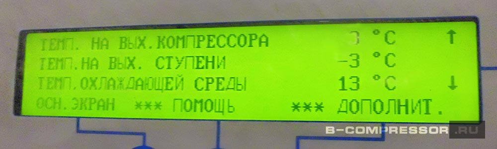
Alarmcode
6981
INLET VALVE POS. FAILURE
7002
ECU COMMUNICATION
7007
ECU RED LAMP
7008
ECU AMBER LAMP
7009
ECU PROTECT LAMP
7010
ECU ENGINE SPEED TOO LOW
7020
ECU ENGINE SPEED ALARM 2
7030
ECU ENGINE COOLANT TEMP. ALARM
7050
ECU ENGINE AIR INLET TEMP. ALARM 1
7100
ECU DPF SOOT LOAD HIGH
7110
PLEASE FORCE DPF REGENERATION !
7120
LOAD PREVENTION — HIGH DPF SOOT LOAD
7130
SOOT LOAD TOO HIGH — CALL ATLAS COPCO
7222
COMBO COMMUNICATION FAILURE
7223
COMBO PA SENSOR WARNING
7224
COMBO RHA SENSOR WARNING
7225
COMBO TA SENSOR WARNING
Details of ECU triggered alarms can be monitored via the ECU DM1 LIST menu
In case of ECU AMBER LAMP or ECU PROTECT
LAMP:
Only possible when engine is running or if
Diagnostics Mode is active.
Access the ECU DM1 LIST menu via Alarm View.
In case of ECU RED LAMP:
Do NOT acknowledge the ECU RED LAMP alarm.
DM1 alarms are automatically copied into the
Alarm View, and can be read there.
For all ECU triggered alarms, the respective SPN code
is shown in the ECU DM1 LIST
A full list of supported SPN codes is provided by the
engine manufacturer.
Alarmtext
For following alarms, the Xc controller also shows full
text next to the SPN code:
ECU — FUEL FILTER PRESSURE
ECU — INTERCOOLER TEMPERATURE
ECU — FUEL PRESSURE
ECU — FUEL FILTER PRESSURE
ECU — WATER IN FUEL
ECU — OIL LEVEL
ECU — OIL FILTER PRESSURE
ECU — OIL PRESSURE
ECU — TURBO BOOST PRESSURE
ECU — TURBO OIL PRESSURE
ECU — INTAKE MANIFOLD TEMPERATURE
ECU — AIR INLET PRESSURE
ECU — COOLANT TEMPERATURE
ECU — COOLANT LEVEL
ECU — SUPPLY VOLTAGE
Failclass
Shutdown
Shutdown
Shutdown
Warning
Warning
Shutdown
Shutdown
Controlled Stop
Controlled Stop
Warning
Inhibit Load
Controlled Stop
Warning
Warning
Warning
Warning
Warning
— 75 —
Trigger
Xc
Xc
ECU
ECU
ECU
Xc
Xc
Xc
Xc
Xc
Xc
Xc
Xc
Xc
Xc
Xc
Xc
ECU — AMBIENT AIR TEMPERATURE
ECU — AIR INLET TEMPERATURE
ECU — FUEL TEMPERATURE
ECU — OIL TEMPERATURE
ECU — ENGINE SPEED
ECU — INJECTOR 1
ECU — INJECTOR 2
ECU — INJECTOR 3
ECU — INJECTOR 4
ECU — INJECTOR 5
ECU — INJECTOR 6
ECU — INJECTOR 7
ECU — INJECTOR 8
ECU — SOOT LOAD