Японская компания Kyocera производит высококачественные лазерные принтеры и МФУ для офисной печати. Их продукция одна из самых востребованных на сегодняшний день. Ведь печатающие устройства Kyocera характеризуются высокой надежностью, износостойкостью и большим сроком эксплуатации. Однако даже их изделия не являются вечными. Со временем принтеры Kyocera начинают сбоить.
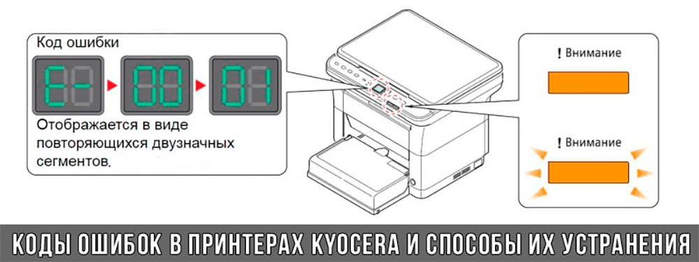
К счастью, оргтехника Kyocera оснащена системой самодиагностики (так же, как и струйные принтеры Canon). Поэтому, в случае возникновения проблемы, устройство самостоятельно выявит уязвимое место и сообщит Вам об этом миганием соответствующего индикатора на панели управления либо кодом ошибки, выведенным на дисплей принтера.
Если Вы не являетесь мастером по обслуживанию принтеров и МФУ Kyocera, то, чтобы понять, о чем сообщает печатающее устройство, Вам потребуется расшифровать указанный им код. Для этого мы добавили в статью таблицу кодов ошибок лазерных принтеров Kyocera серии FS и не только.
Коды ошибок принтеров и МФУ Kyocera, которые можно исправить самостоятельно
|
Код ошибки |
Значение ошибки |
Решение проблемы |
|
E-0001 (E1) |
Поврежден чип картриджа либо установлен неоригинальный картридж. |
Замените установленный картридж оригинальной версией изделия. Если хотите сэкономить, тогда купите и установите новый чип на картридж или перепрошейте принтер Kyocera. Однако предварительно не помешает попробовать сбросить ошибку соответствующей комбинацией клавиш (как это сделать, читайте в статье «Сброс ошибки установки неоригинального картриджа в принтерах Kyocera»). |
|
E-0002 (E2) |
Регион использования картриджа и принтера не совпадают. |
Замените чип или прошейте принтер Kyocera. |
|
E-0003 (E3) |
Заполнена память принтера или МФУ Kyocera. |
Отпечатайте ранее отсканированные листы или очистите очередь печати нажатием кнопки Стоп/Сброс (ранее отсканированные листы также удалятся из памяти принтера, даже если они еще не были распечатаны). |
|
E-0007 (E7) |
Тонер-картридж Kyocera израсходовал ресурс красящего вещества. |
Замените или заправьте картридж Kyocera (если используете совместимый или перезаправленный расходник, то после установки его в принтер не забудьте сбросить ошибку зажатием на 3-5 секунды кнопок [Ок] и [Сброс/Стоп]). |
|
E-0008 (E8) |
Открыта крышка принтера либо не работает датчик закрытия крышек устройства. |
Откройте и еще раз закройте переднюю и заднюю крышку принтера. Во время закрытия Вы должны услышать характерный щелчок. Если не помогло, то причина в неисправности датчика. |
|
E-0009 (E9) |
Лоток приема бумаги полон. |
Уберите все отпечатанные листы бумаги из выходящего лотка. Чтобы возобновить печать, нажмите кнопку [Старт]. |
|
E-0012 (E12) |
Ошибка памяти принтера Kyocera. |
Попробуйте уменьшить разрешение печати. Скорее всего, формат создаваемого отпечатка не соответствует возможностям принтера. |
|
E-0014 (E14) |
Установлен неверный формат бумаги (неподдерживаемый принтером Kyocera). |
Поменяйте бумагу на поддерживаемую принтером либо смените ее формат в настройках печати. Попробуйте обновить программное обеспечение. Возможно, это расширит поддерживаемые принтером Kyocera форматы. |
|
E-0015 (E15) |
Устройство не подключено к электрической сети либо на компьютере нет (не работает) драйвера принтера Kyocera. |
Проверьте подключение печатающего аппарата к электрической сети, а также целостность кабеля. Если ошибка не исчезает, скачайте драйвер принтера Kyocera и установите его на компьютер. |
|
E-0017 (E17) |
Ошибка передачи данных. |
Проверьте подключение принтера к компьютеру. Кабель не должен быть длиннее 5 метров, а также обязан поддерживать стандарт USB 2.0. Кроме того, переустановите драйвер принтера и утилиту Kyocera Client Tool. |
|
E-0018 (E18) |
Очередь печати заполнена. |
Очистите очередь печати нажатием кнопки [Сброс] либо через драйвер принтера. |
|
E-0019 (E19) |
Неверный формат печати. |
Отмените печать нажатием кнопки [Стоп/Сброс]. Выберите в настройках принтера соответствующий режим печати, а также установите в лоток поддерживаемый принтером формат бумаги. |
|
J-0000 (jam0000) |
Замятие бумаги за задней крышкой. |
Откройте крышку и извлеките бумагу. Проверьте надежность крепления бумаги в лотке, а также принтер на наличие посторонних предметов. Еще причина может быть в пружине выходного флажка. Если она растянулась, то может плохо работать фиксатор. Также проблема может быть из-за печки, сделайте ее ревизию, переборку и смазку. |
|
J-0501 (jam0501) |
Бумага застряла в принтере Kyocera |
Извлеките замятую бумагу. Проверьте надежность установки бумаги во входной лоток. Проверьте целостность роликов протяжки бумаги, а также принтер на наличие посторонних предметов. Если не помогло, стоит внимательно осмотреть ребра на направляющей пластине. На них могут образоваться сколы, трещины и заусенцы. Их можно слегка подчистить наждачной бумагой (нулевкой). |
|
J-0511 (jam0511) |
Принтер Kyocera замял бумагу. |
Извлеките замятую бумагу и повторите печать. Если проблема не исчезла, несите принтер в сервис. Скорее всего, изношен ролик протяжки бумаги. |
|
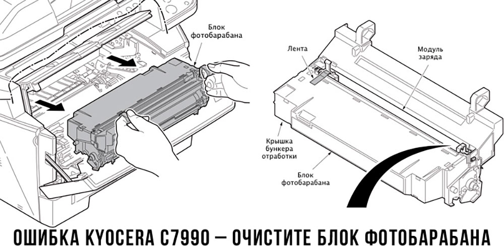
C7990 |
Бункер драм-картриджа (блока фотобарабана) заполнен отработанным тонером либо неисправен счетчик отработки красящего вещества. Еще проблема может быть в главной плате PWB. |
Осуществите чистку драм-картриджа (блока фотобарабана). Если проблема в датчике или плате, то нужно отнести принтер в СЦ на диагностику. |
|
F248 |
Ошибка обработки отпечатываемого материала. |
Перезагрузите принтер. Уберите неподдерживаемые спецсимволы из отпечатка. Обновите ПО принтера Kyocera. Смените режим работы принтера с PDL на GDI (Пуск -> Принтеры -> Свойства -> Параметры устройства). |
|
PF |
Отсутствует бумага в лотке подачи. |
Загрузите листы бумаги во входной лоток. Если принтер по-прежнему не печатает, значит нужно искать проблему в чем-то другом. |
|
1101 |
Ошибка сканирования через сеть из-за неправильного имени SMTP сервера. |
Пропишите DNS-адреса помимо прочих настроек печати по сети. |
|
1102 |
Некорректная настройка сканера для работы через сеть |
Зайдите в Web-панель управления принтером (нужно в адресную строку браузера ввести iP принтера Kyocera). Далее в зависимости от модели введите логин и пароль (Admin/Admin или просто admin00 без логина). Далее следуйте инструкции:
Логин и пароль нужны обязательно, если их нет, то следует создать. |
|
2101 |
Ошибка передачи данных при сканировании через сеть. |
Правильно настройте параметры (как для ошибки 1102), только предварительно отключите на ПК антивирус и брандмауэр. |
Если Вы испытали все способы, но не смогли убрать ошибку, то следует нести печатающее устройство в сервисный центр. Кроме того, есть ряд ошибок (высвечиваемых на дисплее принтера), которые нельзя устранить в домашних условиях. Соответствующие коды ошибок принтеров Kyocera представляем в очередной таблице.
Коды ошибок принтеров и МФУ Kyocera, которые нужно устранять в сервисном центре
|
Код ошибки |
Значение ошибки |
Решение проблемы |
|
0030 |
Неисправность платы управления факсом принтера. |
Замена платы. |
|
0100 |
Неисправность платы управления или флеш-памяти принтера. |
Замена платы. |
|
0120 |
Ошибка чтения mac-адреса из-за неисправности флеш-памяти принтера. |
Замена платы. |
|
0190 |
Неисправность платы управления или флеш-памяти принтера. |
Замена платы. |
|
0630 |
Неисправность платы управления принтера. |
Замена платы. |
|
1020 |
Неисправность мотора, привода или отсутствие контакта. |
Разборка принтера и замена изношенных частей. Проверка надежности подключений, замена разорванных (прогоревших) кабелей. Ремонт или замена привода мотора. |
|
1040 |
Неисправность мотора, привода или отсутствие контакта. |
Разборка принтера и замена изношенных частей. Проверка надежности подключений, замена разорванных (прогоревших) кабелей. Ремонт или замена привода мотора. |
|
2000 |
Неисправность главной платы управления, соединительного кабеля или привода принтера. |
Проверить ремни, шестерни и ролики привода. Смазать или заменить, если есть дефекты. Заменить привод или главную плату. |
|
3100 (C3100) |
Неисправность главной платы, привода сканера, датчика положения или нарушение целостности соединений. |
Проверить наличие разрывов и отсутствия контакта. Смазать или заменить изношенные элементы привода. Заменить привод, главную плату, датчик или соединительный кабель. Если Вам повезло, то возможно забыли отключить фиксатор блока сканера. |
|
3101 |
Сетевой кабель не подсоединен, или нарушена работа концентратора. Еще может быть из-за наличия вирусов в системе или неправильно заданным параметрам сервера SMTP. |
Проверить соединения, правильно настроить параметры сети. |
|
3300 |
Неисправность главной платы, датчика CIS или соединительного кабеля. |
Проверить контакты, заменить плату или датчик. |
|
3500 |
Неисправность главной платы или нарушение соединения контактов. |
Проверить контакты, заменить плату. |
|
4000 (C4000) |
Неисправность главной платы, привода сканера или нарушение соединений. Однако чаще всего ошибка лазера. |
Проверить контакты, заменить плату или привод блока сканера. Почистить лазер, смазать ось полигон-мотора, либо полностью заменить блок лазера. |
|
4200 |
Неисправность главной платы, блока сканера или датчика BD. |
Отключить питание принтера на 30 минут. Если не помогло, то следует заменить привод сканера или главную плату принтера. |
|
6000 (С6000) |
Неисправность главной платы, термостата, печки или нарушение соединения контактов. |
Проверить и поправить контакты. Заменить фьюзер. Ремонт или замена печки, термодатчика, термопредохранителя и т.д. |
|
6020 |
Сгорание термистора или главной платы. |
Замена термистора или главной платы. |
|
6030 |
Неисправность главной платы, термостата или термистора. Возможно, причина в отсутствии контакта. |
Проверить соединения. Заменить плату, термостат или термистор. |
|
6400 |
Неисправность главной платы, отсутствие питания или контакта. |
Заменить плату или источник питания. |
|
F000 |
Неисправность главной платы или отсутствие контакта. |
Проверить соединение ремня безопасности. Заменить ремень или плату управления. |
|
F020 |
Неисправность элементов памяти принтера. |
Перезагрузить принтер. Если ошибка не устранилась – заменить плату управления. |
|
F040 |
Неисправность главной платы принтера. |
Перезагрузить принтер. Если ошибка не устранилась – заменить плату управления. |
|
F05D |
Неисправность главной платы. Сбой программного оборудования привода. Проблемы с прошивкой принтера Kyocera. |
Перезагрузить принтер. Если ошибка не устранилась – заменить плату управления. Перепрошить принтер Kyocera. |
|
F245 F246 F247 F375 |
Принтер Kyocera заблокирован из-за проблемы, вызванной отказом источника питания. |
Нужно перепрошить принтер специальной сервисной микропрограммой. |
Обратите внимание: Если у печатающего устройства нет дисплея, то определить проблему можно по светодиодным индикаторам, встроенным в панель управления принтером. Например, у Kyocera Ecosys P2135D нужно сосчитать количество миганий индикаторов красного цвета и таким образом определить число, указывающее на ту или иную ошибку. В свою очередь, у модели Kyocera FS-1040 все зависит от темпа мигания светодиода с надписью «Внимание!» («Attention!»):
- Мигает медленно – указывает на отсутствие бумаги в лотке или тонера в картридже.
- Мигает быстро – оповещает о проблеме с памятью устройства, переполненном лотке или замятии бумаги, а также об использовании неоригинальных расходных материалов.
- Горит постоянно – говорит о проблемах с картриджем или фотобарабаном либо указывает на открытые крышки принтера.
Чтобы потребитель мог наверняка определить проблему, рекомендуем использовать утилиту Kyocera Client Tool, которая идет в комплекте с драйверами принтера.
Ваше Имя:
Ваш вопрос:
Внимание: HTML не поддерживается! Используйте обычный текст.
Оценка:
Плохо
Хорошо
Введите код, указанный на картинке:


- Code: C0030
- Description: FAX PWB system error
- Causes: The FAX processing cannot be continued due to the FAX firmware error.
- Remedy: 1 Resetting the main power The FAX PWB does not operate properly. Turn off the power switch and the main power switch. After 5s passes, reinstall the FAX PWB, and then turn on the main power switch and the power switch. FAX Installation Guide
2 Firmware upgrade The firmware is faulty. Reinstall the FAX firmware. Firmware Update
3 Replacing the FAX PWB The FAX PWB is faulty. Replace the FAX PWB. FAX Installation Guide
- Code: C0070
- Description: FAX PWB incompatible detection error
- Causes: Abnormal detection of FAX control PWB incompatibility in the initial communication with the FAX control PWB, any normal communication command is not transmitted.
- Remedy: 1 Checking the FAX PWB The incompatible FAX PWB is installed. Install the FAX PWB for the applicable model. FAX Installation Guide
2 Firmware upgrade The FAX firmware is faulty. Reinstall the FAX firmware. Firmware Update
3 Replacing the main PWB The main PWB is faulty. Replace the main PWB. Detaching and reattaching the Main PWB
- Code: C0080
- Description: Optional Printing System device error
Object: Printing System 15 (for 120V, 230V and 240V) - Causes: It is not possible to read FPGA version of the Fiery relay PWB.
- Remedy: 1 Resetting the main power The EEPROM does not operate properly. Turn the power switch and the main power switch off . After 5s passes, turn the main power switch and the power switch on.
2 Replacing the Fiery relay PWB Fiery relay PWB for the other models is installed. Replace Fiery relay PWB which is applicable to the model.
3 Firmware upgrade The version of the main firmware is not supported for the fiery relay PWB. Upgrade the main firmware to the latest version. Firmware Update
4 Checking the Fiery relay PWB The connector is not connected properly. The wire or the PWB is faulty. Clean the terminal of the connectors connecting on the Fiery relay PWB and reconnect the connector. If the wire is faulty, repair or replace it. If not resolved, replace the Fiery relay PWB.
5 Checking the main PWB The connector is not connected properly. The wire or the PWB is faulty. Clean the terminal of the connector (for Fiery relay PWB) on the main PWB and reconnect. If it is not improved, replace Fiery relay PWB.
- Code: C0100
- Description: Backup memory device error
- Causes: An abnormal status is output from the flash memory.
- Remedy: 1 Resetting the main power The flash memory does not operate properly. Turn the power switch and the main power switch off . After 5s passes, turn the main power switch and the power switch on.
2 Checking the main PWB The connector or the FFC is not connected properly. Or, the wire, FFC, the PWB is faulty. Clean the terminal of the connectors on the main PWB, reconnect the connector of the wire, and reconnect the FFC terminal. If the wire or the FFC is faulty, repair or replace them. If not resolved, replace the main PWB. Service Manual — Section 8 ‘PWBs’ Detaching and reattaching the Main PWB
- Code: C0120
- Description: MAC address data error
- Causes: The MAC address data is incorrect.
- Remedy: 1 Resetting the main power The flash memory does not operate properly. Turn the power switch and the main power switch off . After 5s passes, turn the main power switch and the power switch on.
2 Checking the MAC address The MAC address is incorrect. Replace the main PWB when the MAC address is not indicated on the network status page. Detaching and reattaching the Main PWB
- Code: C0130
- Description: Backup memory reading/writing error
- Causes: The reading or writing into the flash memory is unavailable.
- Remedy: 1 Resetting the main power The flash memory does not operate properly. Turn the power switch and the main power switch off . After 5s passes, turn the main power switch and the power switch on.
2 Checking the main PWB The connector or the FFC is not connected properly. Or, the wire, FFC, the PWB is faulty. Clean the terminal of the connectors on the main PWB, reconnect the connector of the wire, and reconnect the FFC terminal. If the wire or the FFC is faulty, repair or replace them. If not resolved, replace the main PWB. Service Manual — Section 8 ‘PWBs’ Detaching and reattaching the Main PWB
- Code: C0150
- Description: Engine EEPROM reading / writing error
- Causes: 1. Five times consecutive detection of no response from the device for more than 5ms on reading / writing.
2. Data read in 2 places does not match 8 consecutive times.
3. Writing data and reading data does not match 8 consecutive times. - Remedy: 1 Resetting the main power The EEPROM on the engine PWB does not operate properly. Turn the power switch and the main power switch off . After 5s passes, turn the main power switch and the power switch on.
2 Checking the EEPROM on the engine PWB The EEPROM is not properly attached. Reattach the EEPROM on the engine PWB. Detaching and reattaching the EEPROM
3 Replacing the EEPROM The EEPROM is faulty. Replace the EEPROM on the engine PWB and execute U169. Next, compare the setting value of the maintenance report outputted at U000 in advance and the setting value of the maintenance report outputted after replacing EEPROM, and change the setting value which are different. (Related maintenance mode: U053, U100, U101, U106, U140, U161, U464, U252, U034, U065, U066, U067) Finally, execute the following maintenance mode in the following order. U119 (for the 35 ppm or faster models) > U411 > U469 [Auto] > U140 [AC Calib] > U140 [Calibration] > U412 [Normal Mode] (for the 35 ppm or faster models) > U464 [Calib] (for the 35 ppm or faster models) > U410 > U155 [Calibration] (The empty waste toner box is necessary.) Maintenanc e Mode List Detaching and reattaching the Engine PWB
4 Replacing the engine PWB The engine PWB is faulty. Replace the engine PWB. Detaching and reattaching the Engine PWB
- Code: C0160
- Description: EEPROM data error
- Causes: The data read from the EEPROM is judged as abnormal.
- Remedy: 1 Resetting the main power The EEPROM on the engine PWB does not operate properly. Turn the power switch and the main power switch off . After 5s passes, turn the main power switch and the power switch on.
2 Executing U021 The storage data in the EEPROM on the engine PWB is faulty. Execute U021. Maintenanc e Mode List
3 Replacing the EEPROM The EEPROM is faulty. Replace the EEPROM on the engine PWB and execute U169. Next, compare the setting value of the maintenance report outputted at U000 in advance and the setting value of the maintenance report outputted after replacing EEPROM, and change the setting value which are different. (Related maintenance mode: U053, U100, U101, U106, U140, U161, U464, U252, U034, U065, U066, U067) Finally, execute the following maintenance mode in the following order. U119 (for the 35 ppm or faster models) > U411 > U469 [Auto] > U140 [AC Calib] > U140 [Calibration] > U412 [Normal Mode] (for the 35 ppm or faster models) > U464 [Calib] (for the 35 ppm or faster models) > U410 > U155 [Calibration] (The empty waste toner box is necessary.) Maintenanc e Mode List Detaching and reattaching the Engine PWB
- Code: C0170
- Description: Charger count error
- Causes: The values in one of the billing counters, life counter or the scanner counter mismatch between the main side and the engine side.
- Remedy: 1 Checking the machine serial No. of the main PWB The main PWB for the different main unit is installed. Check the machine serial Nos of MAIN and ENGINE at U004, and install the correct main PWB if the MAIN No. differs. Maintenanc e Mode List Detaching and reattaching the Main PWB
2 Checking the machine serial No. in the EEPROM on the engine PWB The EEPROM for the different main unit is installed. Check the machine serial Nos of MAIN and ENGINE at U004, and install the correct EEPROM on the engine PWB if the ENGINE machine serial No. differs. Maintenanc e Mode List Detaching and reattaching the EEPROM
3 Checking the main PWB The main PWB is faulty. When the MAIN machine serial No. differs at U004, replace the main PWB and execute U004. Maintenanc e Mode List Detaching and reattaching the Main PWB
4 Checking the EEPROM on the engine PWB The EEPROM is faulty. If the machine serial number in the engine PWB is different at U004, reattach the EEPROM on the engine PWB. If not repairing, replace the EEPROM and execute U169. Next, compare the setting value of the maintenance report outputted at U000 in advance and the setting value of the maintenance report outputted after replacing EEPROM, and change the setting value which are different. (Related maintenance mode: U053, U100, U101, U106, U140, U161, U464, U252, U034, U065, U066, U067) Finally, execute the following maintenance mode in the following order. U119 (for the 35 ppm or faster models) > U411 > U469 [Auto] > U140 [AC Calib] > U140 [Calibration] > U412 [Normal Mode] (for the 35 ppm or faster models) > U464 [Calib] (for the 35 ppm or faster models) > U410 > U155 [Calibration] (The empty waste toner box is necessary.) Maintenanc e Mode List Detaching and reattaching the Engine PWB
5 Replacing the engine PWB The engine PWB is faulty. Replace the engine PWB. Detaching and reattaching the Engine PWB
- Code: C0180
- Description: Machine serial number mismatch
- Causes: The machine serial Nos. in the main PWB and the EEPROM on the engine PWB mismatch when turning the power on.
- Remedy: 1 Checking the machine serial No. of the main PWB The main PWB for the different main unit is installed. Check the machine serial Nos of MAIN and ENGINE at U004, and install the correct main PWB if the MAIN No. differs. Maintenanc e Mode List Detaching and reattaching the Main PWB
2 Checking the machine serial No. in the EEPROM on the engine PWB The EEPROM for the different main unit is installed. Check the machine serial Nos of MAIN and ENGINE at U004, and install the correct EEPROM on the engine PWB if the ENGINE machine serial No. differs. Maintenanc e Mode List Detaching and reattaching the EEPROM
3 Replacing the main PWB The main PWB is faulty. When the MAIN machine serial No. differs at U004, replace the main PWB and execute U004. Maintenanc e Mode List Detaching and reattaching the Main PWB
4 Checking the EEPROM on the engine PWB The EEPROM is faulty. If the machine serial number in the engine PWB is different at U004, reattach the EEPROM on the engine PWB. If not repairing, replace the EEPROM and execute U169. Next, compare the setting value of the maintenance report outputted at U000 in advance and the setting value of the maintenance report outputted after replacing EEPROM, and change the setting value which are different. (Related maintenance mode: U053, U100, U101, U106, U140, U161, U464, U252, U034, U065, U066, U067) Finally, execute the following maintenance mode in the following order. U119 (for the 35 ppm or faster models) > U411 > U469 [Auto] > U140 [AC Calib] > U140 [Calibration] > U412 [Normal Mode] (for the 35 ppm or faster models) > U464 [Calib] (for the 35 ppm or faster models) > U410 > U155 [Calibration] (The empty waste toner box is necessary.) Maintenanc e Mode List Detaching and reattaching the Engine PWB
5 Replacing the engine PWB The engine PWB is faulty. Replace the engine PWB. Detaching and reattaching the Engine PWB
- Code: C0350
- Description: Panel PWB communication error (Electronic volume I2C communication error)
- Causes: Since NACK was received during the I2C communication, the retry was repeated 5 times and the initial command was transmitted, and then the retry was repeated 5 times again. After that, NACK was also received.
- Remedy: 1 Resetting the main power The operation of the operation panel main PWB is faulty. Turn the power switch and the main power switch off . After 5s passes, turn the main power switch and the power switch on.
2 Checking the connection The connector is not connected properly, or the wire is faulty. Clean the terminal of the following wire connectors and reconnect the connectors. If there is no continuity, replace the wire. • Operation panel main PWB — Main PWB • Operation panel main PWB — NFC PWB Service Manual — Section 8 ‘PWBs’
3 Replacing the operation panel main PWB The operation panel main PWB is faulty. Replace the panel main PWB. Detaching and reattaching the Operation Panel Main PWB
4 Replacing the main PWB The main PWB is faulty. Replace the main PWB. Detaching and reattaching the Main PWB
5 Replacing the NFC PWB The NFC PWB is faulty. Replace the NFC PWB.
- Code: C0361
- Description: Communication error between the engine CPU and the feed ASIC
- Causes: The communication with the feed ASIC failed 10 times continuously.
- Remedy: Resetting the main power The engine PWB does not operate properly. Turn the power switch and the main power switch off . After 5s passes, turn the main power switch and the power switch on.
2 Firmware upgrade The firmware is not the latest version. Upgrade the engine firmware to the latest version Firmware Update
3 Checking the connection The connector is not connected properly, or the wire is faulty. Clean the terminal of the following wire connectors and reconnect the connectors. If there is no continuity, replace the wire. • Feed drive PWB — Engine PWB Service Manual — Section 8 ‘PWBs’
4 Replacing the feed drive PWB The feed drive PWB is faulty. Replace the feed drive PWB.
5 Replacing the engine PWB The engine PWB is faulty. Replace the engine PWB. Detaching and reattaching the Engine PWB
- Code: C0362
- Description: Communication error between the engine CPU and the feed ASIC
- Causes: The communication with the feed ASIC failed 10 times continuously.
- Remedy: 1 Resetting the main power The engine PWB does not operate properly. Turn the power switch and the main power switch off . After 5s passes, turn the main power switch and the power switch on.
2 Firmware upgrade The firmware is not the latest version. Upgrade the engine firmware to the latest version Firmware Update
3 Checking the connection The connector is not connected properly, or the wire is faulty. Clean the terminal of the following wire connectors and reconnect the connectors. If there is no continuity, replace the wire. • Feed image PWB — Engine PWB Service Manual — Section 8 ‘PWBs’
4 Replacing the feed image PWB The feed image PWB is faulty. Replace the feed image PWB.
5 Replacing the engine PWB The engine PWB is faulty. Replace the engine PWB. Detaching and reattaching the Engine PWB
- Code: C0640
- Description: Hard Disk error
- Causes: The HDD cannot be accessed properly.
- Remedy: 1 Releasing the partial operation The partial operation is executed. Execute resetting the partial operation at U906. Maintenanc e Mode List
2 (For the main unit without the HDD) Replacing the SSD When installing the 8GB HDD mistakenly, it tries to access the HDD. At that time, the error appears if the HDD is not installed in the main units . Replace with the correct 32GB SSD. Detaching and reattaching the SSD
3 (When abnormal sounds occur) Replacing the HDD The HDD is faulty. Replace the HDD when the abnormal sounds are from the HDD. Detaching and reattaching the HDD
4 Checking the connection The connector is not connected properly. The SATA cable or the wire is faulty. Reconnect the below SATA cable and connector of the wire. If there is no continuity, replace SATA cable or the wire. • HDD — main PWB Service Manual — Section 8 ‘PWBs’
5 Initializing the HDD The HDD storage data is faulty. Execute U024 [FULL] (HDD Format). Maintenanc e Mode List
6 Replacing the HDD The HDD is faulty. Replace the HDD. Detaching and reattaching the HDD
7 Replacing the main PWB The main PWB is faulty. Replace the main PWB. Detaching and reattaching the Main PWB
- Code: C0650
- Description: FAX image storage pair-check error
- Causes: The SSD (FAX image storage) used in other main unit is installed.
- Remedy: 1 Checking the SSD The SSD (FAX image storage) already used in other unit is installed. When installing the SSD used once, replace with the correct SSD. Detaching and reattaching the SSD
2 Executing U671 The SSD (FAX image storage) already used in other unit is reused without executing U671. When installing the SSD used once, execute U671 [FAX Data CLEAR]. Maintenanc e Mode List
3 Reinstalling the SSD The SSD (FAX image storage) is not properly installed. Be sure to install the SSD to the connector on the main PWB. Detaching and reattaching the SSD
4 Replacing the SSD The SSD (FAX image storage) is faulty. Replace with the new SSD. Detaching and reattaching the SSD
5 Replacing the main PWB The main PWB is faulty. Replace the main PWB. Detaching and reattaching the Main PWB
- Code: C0660
- Description: Hard Disk encryption key error
- Causes: 1. The encrypted password entered when replacing the main PWB is not correct.
2. Install SSD which is used in the other machine. - Remedy: 1 (When the issue occurs after replacing the main PWB) Executing U004 The encryption key after replacing the main PWB is faulty. Execute U004 when this issue occurs after replacing the main PWB. Maintenanc e Mode List
2 Replacing the HDD (abnormal sounds) The HDD is faulty. Replace the HDD when the abnormal sounds are from the HDD. Detaching and reattaching the HDD
3 Checking the connection The connector is not connected properly. The SATA cable or the wire is faulty. Reconnect the below SATA cable and connector of the wire. If there is no continuity, replace SATA cable or the wire. • HDD — main PWB Service Manual — Section 8 ‘PWBs’
4 Initializing the HDD The HDD storage data is faulty. Execute U024 [FULL] (HDD Format). Maintenanc e Mode List
5 Replacing the HDD The HDD is faulty. Replace the HDD. Detaching and reattaching the HDD
6 Replacing the main PWB The main PWB is faulty. Replace the main PWB. Detaching and reattaching the Main PWB
- Code: C0670
- Description: Hard Disk overwriting error
- Causes: The area that cannot be properly overwritten exists in a part of the HDD.
- Remedy: 1 Replacing the HDD (abnormal sounds) The HDD is faulty. Replace the HDD when the abnormal sounds are from the HDD. Detaching and reattaching the HDD
2 Checking the connection The connector is not connected properly. The SATA cable or the wire is faulty. Reconnect the below SATA cable and connector of the wire. If there is no continuity, replace SATA cable or the wire. • HDD — main PWB Service Manual — Section 8 ‘PWBs’
3 Initializing the HDD The HDD storage data is faulty. Execute U024 [FULL] (HDD Format). Maintenanc e Mode List
4 Replacing the HDD The HDD is faulty. Replace the HDD. Detaching and reattaching the HDD
5 Replacing the main PWB The main PWB is faulty. Replace the main PWB. Detaching and reattaching the Main PWB
- Code: C0680
- Description: SSD error
- Causes: The SSD cannot be accessed, or the error occurs when accessing to the SSD.
- Remedy: Checking the SSD (if lit after replacing the SSD) An SSD out of specification is installed. Install the SSD matching the memory capacity specification.
2 Resetting the main power The SSD is faulty. Turn the power switch and the main power switch off . After 5s passes, turn the main power switch and the power switch on.
3 Reinstalling the SSD The connection with the main PWB is faulty. Reinstall the SSD on the main PWB. Detaching and reattaching the SSD
4 Initializing the SSD The data stored in the SSD is faulty. Retrieve the SSD storage data at U026, and then initialize the SSD at U024. Maintenanc e Mode List
5 Replacing the SSD The SSD is faulty. Retrieve the SSD storage data at U026, and then replace the SSD. Maintenanc e Mode List Detaching and reattaching the SSD
6 Replacing the main PWB The main PWB is faulty. Replace the main PWB. Detaching and reattaching the Main PWB
- Code: C0800
- Description: Image processing error
- Causes: The print sequence jam (J010x) was detected 2 times continuously.
- Remedy: 1 Checking the image data The image data is faulty. When this issue occurs only when handling the certain image data, check if the image data is faulty.
2 Checking the situation The printing operation of the certain file is faulty. Acquire the job’s log if the phenomenon can be reproduced by specifying the job when the error was detected. Checking Job & Job Operation (Operation Guide — Section 7)
3 Checking the main PWB The connector or the FFC is not connected properly. Or, the wire, FFC, the PWB is faulty. Clean the terminal of the connectors on the main PWB, reconnect the connector of the wire, and reconnect the FFC terminal. If the wire or the FFC is faulty, repair or replace them. If not resolved, replace the main PWB. Service Manual — Section 8 ‘PWBs’ Detaching and reattaching the Main PWB
- Code: C0830
- Description: FAX PWB flash program area checksum error
- Causes: The program stored in the flash memory on the FAX PWB is broken so it cannot perform.
- Remedy: 1 Firmware upgrade The firmware is faulty. Reinstall the FAX firmware. Firmware Update
2 Resetting the main power The FAX PWB is not connected properly. Turn off the power switch and the main power switch. After 5s passes, reinstall the FAX PWB, and then turn on the main power switch and the power switch. FAX Installation Guide
3 Initializing the fax The data in the FAX PWB is faulty. Execute U600 to initialize the FAX. Maintenanc e Mode List
4 Replacing the FAX PWB The FAX PWB is faulty. Replace the FAX PWB. FAX Installation Guide
- Code: C0840
- Description: RTC error (‘Time for maintenance T’ appears)
- Causes: <Check at the start up>
• Setting value of RTC has returned to the past.
• The power has not turned on more than 5 years.
• Setting value of RTC is older than 00:01 January 1st, 2000.
<Check regularly (each 5 minutes) after start up>
• Setting value of RTC has returned to the past which is older than the time previously checked. After detecting C0840, reset the main power to go into disable function and [Time for Maintenance] is displayed. - Remedy: 1 Executing U906 The backup battery on the main PWB is faulty, and so, the RTC settings are erased after unplugging the power cord. Execute U906 and reset the display [Maintenance T]. After that, set the date and time (RTC) through System menu. (It is necessary to perform this process every time when unplug/plug the power cord.) Maintenanc e Mode List Date/Timer/ Energy Saver (Operation Guide — Section
2 Replacing the main PWB The main PWB is faulty, or the backup battery runs out. The user call regarding C0840 is frequent even if performing the previous treatment, replace the main PWB. Detaching and reattaching the Main PWB

- Code: C0850
- Description: TPM security chip error
- Causes: TPM is not accessible or an access error occurs after installing the security kit
- Remedy: 1 Reset the main power Main PWB does not operate properly Turn the power switch and main power switch off. Turn the power switch and main power switch on after passing 5s
2 Upgrading the firmware The firmware version is not the latest Upgrade the firmware to the latest version
3 Replacing main PWB Main PWB is faulty Replace main PWB
- Code: C0870
- Description: PC FAX Image data transmission error
- Causes: Data was not properly transmitted even if the specified times of retry were made when the large volume data is transmitted between the FAX PWB and the main PWB.
- Remedy: 1 Resetting the main power The FAX PWB does not operate properly. Turn the power switch and the main power switch off . After 5s passes, reattach the FAX PWB and turn the main power switch and the power switch on. FAX Installation Guide
2 Initializing the fax The data in the FAX PWB is faulty. Execute U600 to initialize the FAX. Maintenanc e Mode List
3 Firmware upgrade The FAX firmware is faulty. Upgrade the fax firmware to the latest version. Firmware Update
4 Replacing the FAX PWB The FAX PWB is faulty. Replace the FAX PWB. FAX Installation Guide
5 Replacing the main PWB The main PWB is faulty. Replace the main PWB. Detaching and reattaching the Main PWB
6 Executing U024 The data stored in the SSD is faulty. Execute U024 [SSD Format]. Maintenanc e Mode List
- Code: C0920
- Description: FAX file system error
- Causes: The backup data could not be stored since the file system of the flash memory is faulty.
- Remedy: 1 Initializing the fax FAX control values are incorrect Execute U600 to initialize the FAX. Maintenanc e Mode List
2 Resetting the main power The FAX PWB does not operate properly. Turn off the power switch and the main power switch. After 5s passes, reinstall the FAX PWB, and then turn on the main power switch and the power switch. FAX Installation Guide
3 Reconnecting the FAX PWB The FAX PWB is not connected properly. Reinstall FAX PWB to Main PWB. FAX Installation Guide
4 Firmware upgrade The firmware is faulty. Reinstall the FAX firmware. Firmware Update
5 Replacing the FAX PWB The FAX PWB is faulty. Replace the FAX PWB. FAX Installation Guide
- Code: C0950
- Description: FAX job stay error
- Causes: Print processing of the received FAX could not be executed and the job continues staying.
- Remedy: 1 Resetting the main power Print processing is not properly executed. Turn the power switch and the main power switch off . After 5s passes, turn the main power switch and the power switch on.
2 Firmware upgrade The firmware does not properly activate. Upgrade the main firmware to the latest version. Firmware Update
- Code: C0980
- Description: 24V power interruption detection
- Causes: 1. Detected 24 V power off signal for 1s continuously.
2. Another service call occurred when passing 100ms after detecting 24V power failure detection signal, and then 24 power supply was recovered. - Remedy: 1 Resetting the main power The printing process is not properly executed. Turn the power switch and the main power switch off . After 5s passes, turn the main power switch and the power switch on.
2 Checking the connection The connector is not connected properly, or the wire is faulty. Clean the terminal of the following wire connectors and reconnect the connectors. If there is no continuity, replace the wire. • Low voltage PWB — Engine PWB Service Manual — Section 8 ‘PWBs’
3 Replacing the low voltage PWB The low voltage PWB is faulty. When the +24V generation from the low voltage PWB is not stable, and it lowers, replace the low voltage PWB. Detaching and reattaching the Low Voltage PWB
4 Replacing the engine PWB The engine PWB is faulty. Replace the engine PWB. Detaching and reattaching the Engine PWB
- Code: C1000
- Description: MP lift motor error
- Causes: 1. When the MP lift motor rotates in the descending direction, the MP position sensor does not turn on within 1850ms.
2. When the MP lift motor rotates in the ascending direction, the MP position sensor does not turn off within 1600ms. - Remedy: 1 Checking the MP lift plate The MP lift plate does not operate properly. Repair or replace the MP lift plate on the MP tray when it does not move vertically.
2 Firmware upgrade The firmware is not the latest version. Upgrade the engine firmware to the latest version Firmware Update
3 Checking the lift lever The lift lever is not properly attached. Check if the lift lever is vertically shifted by the lift motor cam, or if it has the excessive load. Then, reattach the MP tray. Then, replace the MP tray if it is not fixed.
4 Checking the drive gear The drive gear to lift up the MP lift plate does not rotate properly. Check if the MP lift plate lift-up drive gears rotate smoothly or have no excessive load. And apply the grease (EM-50LP, Part no.: 7BG010009H) to the sliding section and repair the related parts so that they can rotate smoothly.
5 Checking the connection The connector is not connected properly, or the wire is faulty. Clean the terminal of the following wire connectors and reconnect the connectors. If there is no continuity, replace the wire. • Main unit — Paper conveying unit • MP position sensor — Relay connector — Feed drive PWB • Feed drive PWB — Engine PWB Service Manual — Section 8 ‘PWBs’
6 Replacing the MP lift motor The MP lift motor does not operate properly. Replace the MP lift motor.
7 Checking the MP position sensor The MP position sensor is not attached properly. Reattach MP position sensor.
8 Replacing the MP position sensor The MP position sensor is faulty. Replace MP position sensor.
9 Replacing the feed drive PWB The feed drive PWB is faulty. Replace the feed drive PWB.
10 Replacing the engine PWB The engine PWB is faulty. Replace the engine PWB. Detaching and reattaching the Engine PWB
- Code: C1010
- Description: Lift motor 1 error
- Causes: Five times consecutive detection of any one of the below condition.
1. Turning on of lift upper limit sensor is not detected even 16s passed after inserting cassette 1.
2. After turning on lift motor 1, lock signal does not release for 300ms.
3. After detecting lift upper limit sensor 1 OFF during printing, lift upper limit sensor 1 does not turn on even passing 1s from ascending control. - Remedy: 1 Checking the lift plate The lift plate does not operate properly. Repair or replace the lift plate when it does not move vertically.
2 Checking the drive gear The drive gear to lift up the lift plate does not rotate properly. Check if the lift plate lift-up drive gears rotate smoothly or have no excessive load. And apply the grease (EM-50LP, Part no.: 7BG010009H) to the sliding section and repair the related parts so that they can rotate smoothly.
3 Checking the connection The connector is not connected properly, or the wire is faulty. Clean the terminal of the following wire connectors and reconnect the connectors. If there is no continuity, replace the wire. • Lift motor 1 — Feed drive PWB • Feed drive PWB — Engine PWB Service Manual — Section 8 ‘PWBs’
4 Checking lift motor 1 Lift motor 1 is faulty. Check the operation of lift motor 1, and replace it if necessary. Detaching and reattaching the Lift Motor
5 Checking the connection The connector is not connected properly, or the wire is faulty. Clean the terminal of the following wire connectors and reconnect the connectors. If there is no continuity, replace the wire. • Lift upper limit sensor 1 — Feed drive PWB • Feed drive PWB — Engine PWB Service Manual — Section 8 ‘PWBs’
6 Checking lift sensor 1 Lift upper limit sensor 1 is not properly attached, or it is faulty. Reattach lift upper limit sensor 1. Replace it if it is not fixed.
7 Replacing the feed drive PWB The feed drive PWB is faulty. Replace the feed drive PWB.
8 Firmware upgrade The firmware is not the latest version. Upgrade the engine firmware to the latest version Firmware Update
9 Replacing the engine PWB The engine PWB is faulty. Replace the engine PWB. Detaching and reattaching the Engine PWB
- Code: C1020
- Description: Lift motor 2 error
- Causes: Five times consecutive detection of any one of the below condition.
1. Turning on of lift upper limit sensor 2 is not detected even 16s passed after inserting cassette 2.
2. After turning on lift motor 2, lock signal does not release for 300ms.
3. After detecting lift upper limit sensor 2 OFF during printing, lift upper limit sensor 2 does not turn on even passing 1s from ascending control. - Remedy: 1 Checking the lift plate The lift plate does not operate properly. Repair or replace the lift plate when it does not move vertically.
2 Checking the drive gear The drive gear to lift up the lift plate does not rotate properly. Check if the lift plate lift-up drive gears rotate smoothly or have no excessive load. And apply the grease (EM-50LP, Part no.: 7BG010009H) to the sliding section and repair the related parts so that they can rotate smoothly.
3 Checking the connection The connector is not connected properly, or the wire is faulty. Clean the terminal of the following wire connectors and reconnect the connectors. If there is no continuity, replace the wire. • Lift motor 2 — Feed drive PWB • Feed drive PWB — Engine PWB Service Manual — Section 8 ‘PWBs’
4 Checking lift motor 2 Lift motor 2 is faulty. Check the operation of lift motor 2, and replace it if necessary. Detaching and reattaching the Lift Motor
5 Checking the connection The connector is not connected properly, or the wire is faulty. Clean the terminal of the following wire connectors and reconnect the connectors. If there is no continuity, replace the wire. • Lift upper limit sensor 2 — Feed drive PWB • Feed drive PWB — Engine PWB Service Manual — Section 8 ‘PWBs’
6 Checking lift sensor 2 Lift upper limit sensor 2 is not properly attached, or it is faulty. Reattach lift upper limit sensor 2. Then, replace it if it is not fixed.
7 Replacing the feed drive PWB The feed drive PWB is faulty. Replace the feed drive PWB.
8 Firmware upgrade The firmware is not the latest version. Upgrade the engine firmware to the latest version Firmware Update
9 Replacing the engine PWB The engine PWB is faulty. Replace the engine PWB. Detaching and reattaching the Engine PWB
- Code: C1030
- Description: PF lift motor 1 error (Paper Feeder) Object: Paper feeder or Large capacity feeder
- Causes: [PF-7100 (Paper Feeder)] 1. PF lift upper limit sensor 1 does not turn on after passing 16s since cassette 3 was inserted. 2. The lock-up signal is not released for 300ms after turning on of PF lift motor 1. 3. Since PF lift sensor 1 turned off during printing, PF lift upper limit sensor 1 does not turn on after passing 1s from the ascend control.
[PF-7110 (Large Capacity Feeder)] 1. PF lift upper limit sensor 1 does not turn on after passing 24s since cassette 3 was inserted. 2. PF lift upper limit sensor 1 does not turn on after passing 3s from the ascend control when starting printing. - Remedy: 1 Checking the PF lift plate The PF lift plate does not operate properly. Repair or replace the PF lift plate when it does not move vertically.
2 Checking the drive gear The drive gear to lift up the PF lift plate does not rotate properly. Check if the PF lift plate lift-up drive gears rotate smoothly or have no excessive load. And apply the grease (EM-50LP, Part no.: 7BG010009H) to the sliding section and repair the related parts so that they can rotate smoothly.
3 Checking the connection The connector is not connected properly, or the wire is faulty. Clean the terminal of the following wire connectors and reconnect the connectors. If there is no continuity, replace the wire. • PF lift motor 1 — PF PWB Service Manual — Section 8 ‘PWBs’
4 Checking PF lift motor 1 PF lift motor 1 is faulty. Replace PF lift motor 1.
5 Checking the connection The connector is not connected properly, or the wire is faulty. Clean the terminal of the following wire connectors and reconnect the connectors. If there is no continuity, replace the wire. • PF lift upper limit sensor 1 — PF PWB Service Manual — Section 8 ‘PWBs’
6 Checking PF lift sensor 1 PF lift upper limit sensor 1 is not properly attached, or it is faulty. Reattach PF lift upper limit sensor 1. Then, replace it if it is not fixed.
7 Replacing the PF PWB The PF PWB is faulty. Replace the PF PWB. Detaching and reattaching the PF PWB
- Code: C1040
- Description: PF lift motor 2 error (Paper Feeder) Object: Paper feeder or Large capacity feeder
- Causes: [PF-7100 (Paper Feeder)]
1. PF lift upper limit sensor 2 does not turn on after passing 16s since cassette 4 is inserted.
2. The lock-up signal is not released for 300ms after turning on of PF lift motor 2.
3. Since PF lift sensor 2 turned off during printing, PF lift upper limit sensor 2 does not turn on after passing 1s from the ascend control.
[PF-7110 (Large Capacity Feeder)]
1. PF lift upper limit sensor 2 does not turn on after passing 24s since cassette 4 is inserted.
2. PF lift upper limit sensor 2 does not turn on after passing 3s from the ascend control when starting printing. - Remedy: 1 Checking the PF lift plate The PF lift plate does not operate properly. Repair or replace the PF lift plate when it does not move vertically.
2 Checking the drive gear The drive gear to lift up the PF lift plate does not rotate properly. Check if the PF lift plate lift-up drive gears rotate smoothly or have no excessive load. And apply the grease (EM-50LP, Part no.: 7BG010009H) to the sliding section and repair the related parts so that they can rotate smoothly.
3 Checking the connection The connector is not connected properly, or the wire is faulty. Clean the terminal of the following wire connectors and reconnect the connectors. If there is no continuity, replace the wire. • PF lift motor 2 — PF PWB Service Manual — Section 8 ‘PWBs’
4 Replacing PF lift motor 2 PF lift motor 2 is faulty. Replace PF lift motor 2.
5 Checking the connection The connector is not connected properly, or the wire is faulty. Clean the terminal of the following wire connectors and reconnect the connectors. If there is no continuity, replace the wire. • PF lift upper limit sensor 2 — PF PWB Service Manual — Section 8 ‘PWBs’
6 Checking PF lift sensor 2 PF lift upper limit sensor 2 is not properly attached, or it is faulty. Reattach PF lift upper limit sensor 2. Then, replace it if it is not fixed.
7 Replacing the PF PWB The PF PWB is faulty. Replace the PF PWB. Detaching and reattaching the PF PWB
- Code: C1140
- Description: PF lift motor error (Side feeder) Object: Side feeder
- Causes: 1. The PF lift upper limit sensor does not turn on even 30s passed after inserting cassette 5.
2. The lock signal is detected for 200ms continuously during the PF lift motor operation.
3. When start printing, the PF lift upper limit sensor does not detect on even passing 2s from ascending control. - Remedy: 1 Checking the PF lift plate The PF lift plate does not operate properly. Repair or replace the PF lift plate when it does not move vertically.
2 Checking the drive gear The drive gear to lift up the PF lift plate does not rotate properly. Check if the PF lift plate lift-up drive gears rotate smoothly or have no excessive load. And apply the grease (EM-50LP, Part no.: 7BG010009H) to the sliding section and repair the related parts so that they can rotate smoothly.
3 Checking the connection The connector is not connected properly, or the wire is faulty. Clean the terminal of the following wire connectors and reconnect the connectors. If there is no continuity, replace the wire. • PF lift motor — PF PWB Service Manual — Section 8 ‘PWBs’ 4 Checking the PF lift motor The PF lift motor is faulty. Replace the PF lift motor.
5 Checking the connection The connector is not connected properly, or the wire is faulty. Clean the terminal of the following wire connectors and reconnect the connectors. If there is no continuity, replace the wire. • PF lift upper limit sensor — PF PWB Service Manual — Section 8 ‘PWBs’
6 Checking the PF lift upper limit sensor The PF lift upper limit sensor is not properly attached, or it is faulty. Reattach the PF lift upper limit sensor. Then, replace it if it is not fixed.
7 Checking the PF PWB The PF PWB is faulty. Replace the PF PWB. Detaching and reattaching the PF PWB
- Code: C1750
- Description: AK unit type mismatch error
- Causes: Connection of the AK for other model is detected when checking the DF installation status
- Remedy: 1 Checking AK unit AK-7100 is installed. Install AK=7100.
- Code: C1800
- Description: Paper Feeder communication error Object: Paper feeder or Large capacity feeder
- Causes: 1. Communication error was detected 10 times continuously.
2. The ready signal is not notified from the paper feeder or the large capacity feeder within 6s after communication starts. - Remedy: 1 Checking the connection The cable is not properly connected to the main unit. Reconnect the cable into the main unit.
2 Checking the connection The connector is not connected properly, or the wire is faulty. Clean the terminal of the following wire connectors and reconnect the connectors. If there is no continuity, replace the wire. • PF PWB — Engine PWB Service Manual — Section 8 ‘PWBs’
3 Firmware upgrade The firmware is not the latest version. Upgrade the engine firmware to the latest version Firmware Update
4 Replacing the PF PWB The PF PWB is faulty. Replace the PF PWB. Detaching and reattaching the PF PWB
5 Replacing the engine PWB The engine PWB is faulty. Replace the engine PWB. Detaching and reattaching the Engine PWB
- Code: C1820
- Description: Side feeder communication error Object: Side feeder
- Causes: 1. Communication error was detected 10 times continuously.
2. The ready signal is not notified from the side feeder within 6s after communication starts. - Remedy: 1 Checking the connection It is not properly connected to the main unit. Reconnect to the main unit.
2 Checking the connection The connector is not connected properly, or the wire is faulty. Clean the terminal of the following wire connectors and reconnect the connectors. If there is no continuity, replace the wire. • PF PWB — PF PWB (Side feeder) Service Manual — Section 9 ‘Wiring diagram (Options connection)’
3 Firmware upgrade The firmware is not the latest version. Upgrade the engine firmware to the latest version Firmware Update
4 Checking the PF PWB (side feeder) The PF PWB (side feeder) is faulty. Replace PF PWB (side feeder). Detaching and reattaching the PF PWB (Side feeder)
5 Replacing the PF PWB The PF PWB is faulty. Replace the PF PWB. Detaching and reattaching the PF PWB
6 Replacing the engine PWB The engine PWB is faulty. Replace the engine PWB. Detaching and reattaching the Engine PWB
- Code: C1900
- Description: Paper Feeder EEPROM error Object: Paper feeder or Large capacity feeder
For internal count - Causes: The writing data and the reading data mismatch 3 times continuously when writing.
- Remedy: 1 Reconnecting the paper feeder It is not properly connected to the main unit. Reinstall the paper feeder to the main unit. PF-7100 Installation Guide PF-7110 Installation Guide
2 Checking the connection The connector is not connected properly, or the wire is faulty. Reconnect the connector of the wire between the engine PWB and the PF PWB. If the wire is faulty, repair or replace it. If not resolved, replace the PF PWB. Service Manual — Section 8 ‘PWBs’ Detaching and reattaching the PF PWB
3 Replacing the PF PWB The PF PWB is faulty. Replace the PF PWB. Detaching and reattaching the PF PWB
4 Replacing the engine PWB The engine PWB is faulty. Replace the engine PWB. Detaching and reattaching the Engine PWB
- Code: C1920
- Description: Side feeder EEPROM error
Object: Side feeder
For internal count - Causes: The writing data and the reading data mismatch 3 times continuously when writing.
- Remedy: 1 Reconnecting the side feeder It is not properly connected to the main unit. Reinstall the side feeder to the main unit. PF-7120 Installation Guide
2 Checking the connection The connector is not connected properly, or the wire is faulty. Reconnect the connector of the wire between the engine PWB and the PF PWB (side feeder). If the wire is faulty, repair or replace it. If not resolved, replace the PF PWB. Service Manual — Section 9 ‘Wiring diagram (Options connection)’
3 Replacing the PF PWB The PF PWB is faulty. Replace PF PWB (side feeder). Detaching and reattaching the PF PWB (Side feeder)
4 Replacing the engine PWB The engine PWB is faulty. Replace the engine PWB. Detaching and reattaching the Engine PWB
- Code: C1950
- Description: Primary transfer unit EEPROM error
- Causes: 1. Five times consecutive detection of no response from the device for more than 5ms on reading / writing.
2. Data read in 2 places does not match 8 consecutive times.
3. Writing data and reading data does not match 8 consecutive times - Remedy: 1 Reinstalling the primary transfer unit The primary transfer unit is not properly installed. Reinstall the primary transfer unit. Detaching and reattaching the Primary Transfer Unit
2 Checking the connection The connector is not connected properly, or the wire is faulty. Clean the terminal of the following wire connectors and reconnect the connectors. If there is no continuity, replace the wire. • Primary transfer unit — Transfer PWB • Transfer PWB — Feed image PWB • Feed image PWB — Engine PWB Service Manual — Section 8 ‘PWBs’
3 Replacing the primary transfer unit The primary transfer unit is faulty. Replace the primary transfer unit. Detaching and reattaching the Primary Transfer Unit
4 Replacing the feed image PWB The feed image PWB is faulty. Replace the feed image PWB.
5 Replacing the engine PWB The engine PWB is faulty. Replace the engine PWB. Detaching and reattaching the Engine PWB
- Code: C2102
- Description: Developer motor CY error
Object: 35ppm or faster models - Causes: 1. After the developer motor CY drive starts, the ready signal does not reach to L level even passing 2s.
2. After the developer motor CY stabilizes, the ready signal shows H level for 2s continuously. - Remedy: 1 Checking the developer drive section The developer drive section is faulty. Replace the developer unit drive gear if it is faulty.
2 Checking the developer roller The developer roller is faulty. Check if the developer roller rotates, and replace the developer unit if not rotating. Detaching and reattaching the Developer Unit
3 Checking the drive parts The drive from the developer motor is not transmitted properly. Execute U030 [DLP(CMY)] to check the developer motor CY operation. Check if the drive gears rotate and have no excessive load, and apply the grease (EM-LP, Part no: 7BG010009H) to the sliding section and repair the related parts so that they can rotate smoothly. Maintenanc e Mode List
4 Checking the connection The connector is not connected properly, or the wire is faulty. Clean the terminal of the following wire connectors and reconnect the connectors. If there is no continuity, replace the wire. • Developer motor CY — Feed image PWB • Feed image PWB — Engine PWB Service Manual — Section 8 ‘PWBs’
5 Checking the developer motor The developer motor is faulty. Reattach developer motor CY. If not repaired, replace it.
6 Replacing the feed image PWB The feed image PWB is faulty. Replace the feed image PWB.
7 Firmware upgrade The firmware is not the latest version. Upgrade the engine firmware to the latest version Firmware Update
8 Replacing the engine PWB The engine PWB is faulty. Replace the engine PWB. Detaching and reattaching the Engine PWB
- Code: C2103
- Description: Developer motor CMY error / Developer motor M error
Remarks: Developing motor CMY: 32/25ppm models, Developing motor M: 35ppm or faster models - Causes: 1. After the developer motor CMY drive or the developer motor M drive start, the ready signal does not reach to L level even passing 2s.
2. After the developer motor CMY or the developer motor M stabilize, the ready signal shows H level for 2s continuously. - Remedy: 1 Checking the developer drive section The developer drive section is faulty. Replace the developer unit drive gear if it is faulty.
2 Checking the developer roller The developer roller is faulty. Check if the developer roller rotates, and replace the developer unit if not rotating. Detaching and reattaching the Developer Unit
3 Checking the drive parts The drive from the developer motor is not transmitted properly. Execute U030 [DLP(CMY)] to check the developer motor CMY operation or the developer motor M operation. Check if the drive gears rotate and have no excessive load, and apply the grease (EM-LP, Part no: 7BG010009H) to the sliding section and repair the related parts so that they can rotate smoothly. Maintenanc e Mode List
4 Checking the connection The connector is not connected properly, or the wire is faulty. Clean the terminal of the following wire connectors and reconnect the connectors. If there is no continuity, replace the wire. • Developer motor CMY — Feed image PWB(For the 25/32ppm models) • Developer motor M — Feed image PWB(For the 35ppm or faster models) • Feed image PWB — Engine PWB Service Manual — Section 8 ‘PWBs’
5 Checking the developer motor The developer motor is faulty. Reattach developer motor CMY or developer motor M. If not repaired, replace them. Maintenanc e Mode List
6 Replacing the feed image PWB The feed image PWB is faulty. Replace the feed image PWB.
7 Firmware upgrade The firmware is not the latest version. Upgrade the engine firmware to the latest version Firmware Update
8 Replacing the engine PWB The engine PWB is faulty. Replace the engine PWB. Detaching and reattaching the Engine PWB
- Code: C2201
- Description: Drum motor K steady-state error
- Causes: The ready signal is at the H level for 2s continuously after drum motor K becomes stable.
- Remedy: 1 Checking drum motor K The drum motor K drive is faulty. Execute U030 [Drum K] to check the drum motor K operation. Check if the drive gears rotate and have no excessive load, and apply the grease (EM-LP, Part no: 7BG010009H) to the sliding section and repair the related parts so that they can rotate smoothly. Maintenanc e Mode List
2 Checking the connection The connector is not connected properly, or the wire is faulty. Clean the terminal of the following wire connectors and reconnect the connectors. If there is no continuity, replace the wire. • Drum motor K — Feed image PWB • Feed image PWB — Engine PWB Service Manual — Section 8 ‘PWBs’
3 Checking drum unit K The drum unit is faulty. Check if the drum or the drum screw is rotated manually, and replace the drum unit if not rotated. Detaching and reattaching the Drum Unit
4 Checking drum motor K Drum motor K is faulty. Replace drum motor K.
5 Replacing the feed image PWB The feed image PWB is faulty. Replace the feed image PWB.
6 Firmware upgrade The firmware is not the latest version. Upgrade the engine firmware to the latest version Firmware Update
7 Replacing the engine PWB The engine PWB is faulty. Replace the engine PWB. Detaching and reattaching the Engine PWB
- Code: C2203
- Description: Drum motor CMY steady-state error
- Causes: The ready signal is at the H level for 2s continuously after drum motor CMY become stable.
- Remedy: Checking drum motor CMY The drum motor CMY drive are faulty. Execute U030 [Drum COL] to check the drum motor CMY operation. Check if the drive gears rotate and have no excessive load, and apply the grease (EM-LP, Part no: 7BG010009H) to the sliding section and repair the related parts so that they can rotate smoothly. Maintenanc e Mode List
2 Checking the connection The connector is not connected properly, or the wire is faulty. Clean the terminal of the following wire connectors and reconnect the connectors. If there is no continuity, replace the wire. • Drum motor CMY — Feed image PWB • Feed image PWB — Engine PWB Service Manual — Section 8 ‘PWBs’
3 Replacing drum motor CMY Drum motor CMY are faulty. Replace drum motor CMY.
4 Checking the drum unit and the developer unit The drum unit is faulty. Check if the drum or the drum screw is rotated manually, and replace the drum unit if not rotated. Detaching and reattaching the Drum Unit
5 Replacing the feed image PWB The feed image PWB is faulty. Replace the feed image PWB.
6 Firmware upgrade The firmware is not the latest version. Upgrade the engine firmware to the latest version Firmware Update
7 Replacing the engine PWB The engine PWB is faulty. Replace the engine PWB. Detaching and reattaching the Engine PWB
- Code: C2300
- Description: Fuser motor error
- Causes: The ready signal is at the H level for 1.5s continuously during the fuser motor drive.
- Remedy: 1 Checking the fuser motor The fuser motor operation is faulty. Execute U030 [Fuser] to check the fuser motor operation. Check if the drive gears rotate and have no excessive load, and apply the grease (EM-LP, Part no: 7BG010009H) to the sliding section and repair the related parts so that they can rotate smoothly. Maintenanc e Mode List
2 Checking the connection The connector is not connected properly, or the wire is faulty. Clean the terminal of the following wire connectors and reconnect the connectors. If there is no continuity, replace the wire. • Fuser motor — Feed drive PWB • Feed drive PWB — Engine PWB Service Manual — Section 8 ‘PWBs’
3 Replacing the fuser unit The fuser unit is faulty. Replace the fuser unit. Detaching and reattaching the Fuser Unit
4 Replacing the fuser drive unit The fuser drive unit is faulty. Replace the fuser drive unit. Detaching and reattaching the Fuser Drive Unit
5 Replacing the fuser motor The fuser motor is faulty. Replace the fuser motor. Detaching and reattaching the Fuser Drive Unit
6 Replacing the feed drive PWB The feed drive PWB is faulty. Replace the feed drive PWB.
7 Firmware upgrade The firmware is not the latest version. Upgrade the engine firmware to the latest version Firmware Update
8 Replacing the engine PWB The engine PWB is faulty. Replace the engine PWB. Detaching and reattaching the Engine PWB
- Code: C2500
- Description: Feed motor error
- Causes: The ready signal is not at the L level after passing 2s since the feed motor drive was started.
- Remedy: 1 Checking the feed motor The operation of the feed motor is faulty. Execute U030 [Feed] to check the feed motor operation. Check if the drive gears rotate and have no excessive load, and apply the grease (EM-LP, Part no: 7BG010009H) to the sliding section and repair the related parts so that they can rotate smoothly. Maintenanc e Mode List
2 Checking the connection The connector is not connected properly, or the wire is faulty. Clean the terminal of the following wire connectors and reconnect the connectors. If there is no continuity, replace the wire. • Feed motor — Feed drive PWB • Feed drive PWB — Engine PWB Service Manual — Section 8 ‘PWBs’
3 Replacing the feed motor The feed motor is faulty. Replace the feed motor.
4 Replacing the feed drive unit The feed drive unit is faulty. Replace feed drive unit. Detaching and reattaching the Feed Drive Unit
5 Replacing the feed drive PWB The feed drive PWB is faulty. Replace the feed drive PWB.
6 Firmware upgrade The firmware is faulty. Upgrade the engine firmware to the latest version Firmware Update
7 Replacing the engine PWB The engine PWB is faulty. Replace the engine PWB. Detaching and reattaching the Engine PWB
8 Replacing the feed image PWB The power can’t be supplied to the feed drive PWB. Replace the feed image PWB.
- Code: C2600
- Description: PF feed motor error
- Causes: The ready signal is not at the L level (stable rotation) after passing 1s since the PF feed motor drive started.
- Remedy: 1 Checking the PF feed motor The PF feed motor is not properly connected, or it is faulty. Execute U247 [2PF] or [LCF] > [Motor On] to check the paper feed operation. If the PF feed motor does not operate properly, reconnect the connector of the motor. Check if the PF feed roller and the drive gears rotate smoothly and have no excessive load, apply the grease (EM-50LP, Part no.: 7BG010009H) to the sliding section and repair the related parts so that they can rotate smoothly. Maintenanc e Mode List
2 Checking the connection The connector is not connected properly, or the wire is faulty. Clean the terminal of the following wire connectors and reconnect the connectors. If there is no continuity, replace the wire. • PF feed motor — PF PWB • PF PWB — Engine PWB (Drawer connector between the paper feeder and the main unit) Service Manual — Section 8 ‘PWBs’
3 Replacing the PF feed motor The PF feed motor is faulty. Replace the PF feed motor. Detaching and reattaching the PF Drive Unit
4 Firmware upgrade The engine firmware or the PF firmware is faulty. Upgrade the engine firmware and the PF firmware to the latest version. Firmware Update
5 Replacing the PF PWB The PF PWB is faulty. Replace the PF PWB. Detaching and reattaching the PF PWB
6 Replacing the engine PWB The engine PWB is faulty. Replace the engine PWB. Detaching and reattaching the Engine PWB
- Code: C2700
- Description: Primary / secondary transfer release error
- Causes: The belt release motor was pressed or drove to the releasing direction, and releasing or pressing condition continued for 2.3s.
- Remedy: 1 Checking the drive parts The drive transmission of the belt release motor is faulty. Execute U030 [Belt Lift]. If the motor drive is not transmitted, repair the drive transmission parts. Maintenanc e Mode List 2 Checking the connection The connector is not connected properly, or the wire is faulty. Clean the terminal of the following wire connectors and reconnect the connectors. If there is no continuity, replace the wire. • Belt release motor — Feed image PWB • Belt release sensor — Feed image PWB • Feed image PWB — Engine PWB • Feed image PWB — Low voltage PWB Service Manual — Section 8 ‘PWBs’
3 Checking the belt release sensor The belt release sensor comes off. Reattach or replace the belt release sensor.
4 Checking the belt release motor The belt release motor is not operated correctly. Reattach or replace the belt release motor.
5 Replacing the primary transfer unit The primary transfer roller liftup drive section is faulty. Replace the primary transfer unit. Detaching and reattaching the Primary Transfer Unit 6 Replacing the feed image PWB The feed image PWB is faulty. Replace the feed image PWB.
7 Firmware upgrade The engine firmware is faulty. Upgrade the engine firmware to the latest version Firmware Update
8 Replacing the engine PWB The engine PWB is faulty. Replace the engine PWB. Detaching and reattaching the Engine PWB
9 Replacing the low voltage PWB The power is not supplied from the low voltage PWB to the belt release motor. If the power is not supplied from the low voltage PWB, replace the low voltage PWB. Detaching and reattaching the Low Voltage PWB
- Code: C2760
- Description: Developer K/Transfer belt motor startup error
- Causes: 1. FG pulse of the motor does not enter for 2s continuously during driving the motor.
2. FG pulse exceeding 4000rpm was detected 10 times continuously.
3. The condition where the target speed +/-6.25% of the motor deviated continued for 2s. - Remedy: 1 Replacing the primary transfer unit The transfer belt is faulty. Replace the primary transfer unit. Detaching and reattaching the Primary Transfer Unit
2 Checking the developer K/ transfer belt motor drive transmission section The drive transmission of the developer K/transfer belt motor is faulty. Execute U030 [DLP(K)] to check the excessive load is not applied to the drive gears, roller and the belt by rotating them. After that, clean the drive section of the primary transfer unit. Maintenanc e Mode List
3 Checking the connection The connector is not connected properly, or the wire is faulty. Clean the terminal of the following wire connectors and reconnect the connectors. If there is no continuity, replace the wire. • Developer K/Transfer belt motor — Feed image PWB • Feed image PWB — Engine PWB Service Manual — Section 8 ‘PWBs’
4 Checking the developer K/ transfer belt motor The developer K/transfer belt motor is faulty. Reattach the developer K/transfer belt motor and reconnect the connector. If not repaired, replace it.
5 Firmware upgrade The firmware is faulty. Upgrade the engine firmware to the latest version Firmware Update 6 Replacing the feed image PWB The feed image PWB is faulty. Replace the feed image PWB.
7 Replacing the engine PWB The engine PWB is faulty. Replace the engine PWB. Detaching and reattaching the Engine PWB
- Code: C2810
- Description: Waste toner motor error
- Causes: 1. The lock detection signal shows L level during driving the waste toner motor. (0.5s x 3 times retry continuously with 2ms cycle)
2. Low level of the lock detection signal can not detect within 50ms from the switching REM signal L to H. (3 times retry with 50ms cycle) - Remedy: 1 Checking the waste toner box The waste toner box is not properly installed. Reinstall the waste toner box. Replacing the Waste Toner Box (Operation Guide — Section 10)
2 Checking the waste toner motor The waste toner motor does not operate properly. Execute U030 [Toner Recovery] to check whether the waste toner motor operation has an excessive load or not. Then, repair it if necessary. Maintenanc e Mode List
3 Checking the drive gear The drive gear does not rotate properly. Check if the excessive load is not applied to the drive gears by rotating the gears, and clean the drive gears and the bushing, etc. 4 Replacing the waste toner box The waste toner box is faulty. Replace the waste toner box. Replacing the Waste Toner Box (Operation Guide — Section 10)
5 Checking the waste toner motor The waste toner motor is not properly connected. Reinsert the connector into the waste toner motor.
6 Checking the connection The connector is not connected properly, or the wire is faulty. Clean the terminal of the following wire connectors and reconnect the connectors. If there is no continuity, replace the wire. • Waste toner motor — Engine PWB Service Manual — Section 8 ‘PWBs’
7 Firmware upgrade The engine firmware is faulty. Upgrade the engine firmware to the latest version Firmware Update
8 Replacing the engine PWB The engine PWB is faulty. Replace the engine PWB. Detaching and reattaching the Engine PWB
- Code: C2840
- Description: Belt cleaning motor error
- Causes: 1. FG pulse of the motor does not enter for 2s continuously during driving the motor.
2. FG pulse exceeding 4000rpm was detected 10 times continuously.
3. The condition where the target speed +/-6.25% of the motor deviated continued for 2s. - Remedy: 1 Checking the primary transfer unit The primary transfer unit is not properly installed. Reinstall the primary transfer unit. Detaching and reattaching the Primary Transfer Unit
2 Cleaning the primary transfer cleaning section The roller in the primary transfer cleaning section does not rotate properly. Remove the waste toner remaining in the primary transfer cleaning section.
3 Checking the connection The connector is not connected properly, or the wire is faulty. Clean the terminal of the following wire connectors and reconnect the connectors. If there is no continuity, replace the wire. • Belt cleaning motor — Transfer PWB • Transfer PWB — Transfer connect PWB • Transfer connect PWB — Feed image PWB • Feed image PWB — Feed drive PWB • Feed image PWB — Engine PWB Service Manual — Section 8 ‘PWBs’
4 Checking the belt cleaning motor The belt cleaning motor does not operate properly. Reattach the belt cleaning motor. If not repaired, replace it.
5 Replacing the primary transfer unit The cleaning drive section of the primary transfer unit is faulty. Transfer PWB or transfer connection PWB is faulty. Replace the primary transfer unit. Detaching and reattaching the Primary Transfer Unit
6 Replacing the feed image PWB The feed image PWB is faulty. Replace the feed image PWB.
7 Firmware upgrade The engine firmware is faulty. Upgrade the engine firmware to the latest version Firmware Update
8 Replacing the engine PWB The engine PWB is faulty. Replace the engine PWB. Detaching and reattaching the Engine PWB 8 Replacing the feed drive PWB The feed drive PWB is faulty. Replace the feed drive PWB.
- Code: C3100
- Description: Carriage error
- Causes: The position of the home position sensor (turning on / off) mismatches when turning the main power on or finishing the original scan by the scanner.
- Remedy: 1 Unlocking the primary mirror unit The primary mirror unit is not unlocked. Unlock the primary mirror unit. Unlocking the scanner mirror frame
2 Removing foreign objects and applying the grease A load is applied to the scanner movement. Confirm the operation of the mirror unit by executing U073 or moving by manual operation. If there is a heavy load on it, check whether there are any foreign objects on the scanner wire or the scanner wire drum, and then clean it. After that, apply grease (PG-671) on the scanner rail. Maintenanc e Mode List
3 Checking the scanner wires The scanner wires are dirty or come off. Clean the scanner wire or reattach it. Detaching and reattaching the Scanner Wires
4 Checking the scanner motor The scanner motor is faulty. Reattach the scanner motor and reconnect the connector. If not repaired, replace it.
5 Checking the belt tension of the scanner motor A load is applied to the scanner movement since the belt tension is improper. Adjust the scanner motor belt tension properly.
6 Checking the connection The connector is not connected properly, or the wire is faulty. Clean the terminal of the following wire connectors and reconnect the connectors. If there is no continuity, replace the wire. • Scanner motor — Engine PWB Service Manual — Section 8 ‘PWBs’
7 Checking the home position sensor The home position sensor is not properly attached. Reattach the home position sensor.
8 Checking the connection The connector is not connected properly, or the wire is faulty. Clean the terminal of the following wire connectors and reconnect the connectors. If there is no continuity, replace the wire. • Home position sensor — Engine PWB Service Manual — Section 8 ‘PWBs’
9 Checking the home position sensor The home position sensor is faulty. Replace the home position sensor.
10 Firmware upgrade The firmware is not the latest version. Upgrade the engine firmware to the latest version Firmware Update 11 Replacing the engine PWB The engine PWB is faulty. Replace the engine PWB. Detaching and reattaching the Engine PWB
- Code: C3200
- Description: LED lamp startup error
- Causes: 1. The white reference data acquired by lighting the lamp at the initial operation is at the specified value or less. (2 or more LED lamps do not light.)
2. The black level adjustment of the A/D convertor on the CCD PWB is faulty. (The image contrast is faulty due to the transmission error of the A/D conversion data signal or clock.) - Remedy: 1 Checking the LED lamp The LED lamp does not light. Check if the LED lamp lights by executing U061 [CCD]. If it does not light, replace the lamp unit and execute U411 [Table(ChartA)]. Detaching and reattaching the Lamp Unit Maintenanc e Mode List
2 Checking the connection FFC is not connected properly. Or it is faulty. Clean the FFC terminals of the following FFC and reconnect them. If the FFC terminal is deformed or broken, replace the FFC. • CCD PWB — Engine PWB • LED PWB — CCD PWB Service Manual — Section 8 ‘PWBs’
3 Replacing the lens unit The CCD PWB is faulty. Replace the lens unit and execute U411. Detaching and reattaching the Lens Unit Maintenanc e Mode List
4 Firmware upgrade The firmware is faulty. Upgrade the engine firmware to the latest version Firmware Update
5 Replacing the engine PWB The engine PWB is faulty. Replace the engine PWB. Detaching and reattaching the Engine PWB
- Code: C3210
- Description: CIS lamp error
Object: Dual scan DP - Causes: The input data did not exceed threshold for 5s when lighting the CIS lamp.
- Remedy: 1 Releasing the partial operation The partial operation is executed. Execute resetting the partial operation at U906. Maintenanc e Mode List
2 Checking the DPCIS The CIS lamp does not light. Check if the CIS lamp lights by executing U061 [CIS]. If it does not light, replace the DPCIS and execute U091 and U411. Detaching and reattaching the DP CIS Maintenanc e Mode List
3 Cleaning the CIS glass and the CIS roller The CIS glass or the CIS roller is dirty. Clean the CIS glass and the CIS roller. 4 Checking the DPSHD PWB The DPSHD PWB is not properly connected. Reconnect the DPSHD PWB to the DPCIS.
5 Checking the connection The connector is not connected properly, or the wire is faulty. Clean the terminal of the following wire connectors and reconnect the connectors. If there is no continuity, replace the wire. • DP SHD PWB — DP PWB • DP PWB — Engine PWB Service Manual — Section 8 ‘PWBs’
6 Firmware upgrade The firmware is faulty. Upgrade the DP firmware to the latest version. Firmware Update
7 Replacing the DPSHD PWB The DPSHD PWB is faulty. Replace the DPSHD PWB.
8 Replacing the DP PWB The DP PWB is faulty. Replace the DP PWB. Detaching and reattaching the DF PWB
9 Replacing the engine PWB The engine PWB is faulty. Replace the engine PWB. Detaching and reattaching the Engine PWB
- Code: C3300
- Description: CCD AGC error
- Causes: The brightness of the LED lamps is darker (1 LED lamp does not turn on) or brighter than anticipated when executing the AGC process for the CCD lamp.
- Remedy: 1 Checking the LED lamp The LED lamp is broken. Check if the LED lamp lights by executing U061 [CCD]. If it does not light, replace the lamp unit and execute U411 [Table(ChartA)]. Detaching and reattaching the Lamp Unit Maintenanc e Mode List
2 Cleaning the backside of the contact glass The white reference sheet is dirty. Clean the white reference sheet at the backside of the contact glass. Detaching and reattaching the Contact Glass (Section 4 ‘Detaching and reattaching the Lens unit’)
3 Checking the connection FFC is not connected properly. Or it is faulty. Clean the FFC terminals of the following FFC and reconnect them. If the FFC terminal is deformed or broken, replace the FFC. • CCD PWB — Engine PWB • LED PWB — CCD PWB Service Manual — Section 8 ‘PWBs’
4 Firmware upgrade The firmware is faulty. Upgrade the engine firmware to the latest version Firmware Update
5 Replacing the lens unit The CCD PWB is faulty. Replace the lens unit and execute U411. Detaching and reattaching the Lens Unit Maintenanc e Mode List
6 Replacing the engine PWB The engine PWB is faulty. Replace the engine PWB. Detaching and reattaching the Engine PWB
- Code: C3310
- Description: CIS AGC error
Object: Dual scan DP
For internal count - Causes: The DPCIS could not acquire the correct white reference value while AGC process was executed.
- Remedy: 1 Releasing the partial operation The partial operation is executed. Execute resetting the partial operation at U906. Maintenanc e Mode List
2 Cleaning the CIS glass and the CIS roller The CIS glass or the CIS roller is dirty. Clean the CIS glass and the CIS roller.
3 Firmware upgrade The firmware is faulty. Upgrade the engine firmware to the latest version Firmware Update
4 Checking the DPSHD PWB The DPSHD PWB is not properly connected. Reconnect the DPSHD PWB to the DPCIS.
5 Replacing the DPSHD PWB The DPSHD PWB is faulty. Replace the DPSHD PWB.
6 Replacing the DPCIS The DPCIS is faulty. Replace the DPCIS, and then execute U091 and U411. Detaching and reattaching the DP CIS Maintenanc e Mode List
7 Replacing the DP PWB The DP PWB is faulty. Replace the DP PWB. Detaching and reattaching the DF PWB
8 Replacing the engine PWB The engine PWB is faulty. Replace the engine PWB. Detaching and reattaching the Engine PWB
- Code: C3500
- Description: Communication error between the scanner and the ASIC
- Causes: The communication error was detected during the communication between the scanner ASIC and the engine CPU.
- Remedy: 1 Replacing the engine PWB The engine PWB is faulty. Replace the engine PWB. Detaching and reattaching the Engine PWB
- Code: C3600
- Description: Scanner sequence error
- Causes: The program internal processing error of the scanner sequence occurs.
- Remedy: 1 Executing U021 The memory operation is faulty. Execute U021. Maintenanc e Mode List
2 Replacing the engine PWB The engine PWB is faulty. Replace the engine PWB. Detaching and reattaching the Engine PWB
- Code: C3800
- Description: AFE error
- Causes: When writing, writing data and reading data does not match 3 times continuously. There is no response from AFE for 100ms.
- Remedy: 1 Checking the connection FFC is not connected properly. Or it is faulty. Clean the FFC terminals of the following FFC and reconnect them. If the FFC terminal is deformed or broken, replace the FFC. • CCD PWB — Engine PWB Service Manual — Section 8 ‘PWBs’
2 Replacing the lens unit The CCD PWB is faulty. Replace the lens unit and execute U411. Detaching and reattaching the Lens Unit Maintenanc e Mode List
3 Replacing the engine PWB The engine PWB is faulty. Replace the engine PWB. Detaching and reattaching the Engine PWB
- Code: C4001
- Description: Polygon motor synchronization error
- Causes: The ready signal is not at the L level after passing 15s since the polygon motor drive was started.
- Remedy: 1 Checking the connection FFC is not connected properly. Or it is faulty. Clean the FFC terminals of the following FFC and reconnect them. If the FFC terminal is deformed or broken, replace the FFC. • LSU (APC PWB) — Engine PWB Service Manual — Section 8 ‘PWBs’
2 Checking the polygon motor The polygon motor does not rotate properly. Check the rotation sound of the polygon motor, and reattach or replace the LSU if it does not rotate properly. Detaching and reattaching the LSU
3 Firmware upgrade The engine firmware is faulty. Upgrade the engine firmware to the latest version Firmware Update 4 Replacing the engine PWB The engine PWB is faulty. Replace the engine PWB. Detaching and reattaching the Engine PWB
- Code: C4011
- Description: Polygon motor steady-state error
- Causes: The ready signal is at the H level for 15s continuously after the polygon motor drive becomes stable.
- Remedy: 1 Checking the connection FFC is not connected properly. Or it is faulty. Clean the FFC terminals of the following FFC and reconnect them. If the FFC terminal is deformed or broken, replace the FFC. • LSU (APC PWB) — Engine PWB Service Manual — Section 8 ‘PWBs’
2 Checking the polygon motor The polygon motor does not rotate properly. Check the rotation sound of the polygon motor, and reattach or replace the LSU if it does not rotate properly. Detaching and reattaching the LSU
3 Firmware upgrade The engine firmware is faulty. Upgrade the engine firmware to the latest version Firmware Update
4 Replacing the engine PWB The engine PWB is faulty. Replace the engine PWB. Detaching and reattaching the Engine PWB
- Code: C4101
- Description: BD initialization error
- Causes: The BD signal was not detected for 1s after driving the polygon motor.
- Remedy: 1 Checking the connection FFC is not connected properly. Or it is faulty. Clean the FFC terminals of the following FFC and reconnect them. If the FFC terminal is deformed or broken, replace the FFC. • LSU (APC PWB) — Engine PWB Service Manual — Section 8 ‘PWBs’
2 Checking the LSU The BD sensor or the laser diode is faulty. Reinstall or replace the LSU while paying attention to the static electricity. Detaching and reattaching the LSU
3 Firmware upgrade The engine firmware is faulty. Upgrade the engine firmware to the latest version Firmware Update
4 Replacing the engine PWB The engine PWB is faulty. Replace the engine PWB. Detaching and reattaching the Engine PWB
- Code: C4201
- Description: BD steady-state error
- Causes: The BD signal is not detected during the laser lighting.
- Remedy: 1 Checking the connection FFC is not connected properly. Or it is faulty. Clean the FFC terminals of the following FFC and reconnect them. If the FFC terminal is deformed or broken, replace the FFC. • LSU (APC PWB) — Engine PWB Service Manual — Section 8 ‘PWBs’
2 Checking the LSU The BD sensor or the laser diode is faulty. Reinstall or replace the LSU while paying attention to the static electricity. Detaching and reattaching the LSU
3 Firmware upgrade The engine firmware is faulty. Upgrade the engine firmware to the latest version Firmware Update
4 Replacing the engine PWB The engine PWB is faulty. Replace the engine PWB. Detaching and reattaching the Engine PWB
- Code: C4600
- Description: LSU cleaning motor error
- Causes: The LSU cleaning motor lock-up was detected, or the motor continued to be shifted in the same direction for 8s or more.
- Remedy: 1 Executing the Laser Scanner Cleaning The LSU cleaning drive gear and the cleaning pad have the load and so they are not shifted smoothly. Execute Laser Scanner Cleaning. Adjust/ Maintenanc e Menu (Operation Guide — Section 10)
2 Cleaning the LSU cleaning drive gear and the cleaning pad The LSU cleaning drive gear and the cleaning pad have the load and so they are not shifted smoothly. Clean the LSU cleaning drive gear and the cleaning pad.
3 Replacing the LSU The LSU cleaning drive gear, cleaning wire or the cleaning pad are deformed, or they are faulty. Replace the LSU. Detaching and reattaching the LSU
4 Checking the connection The connector or FFC is not connected properly. Or, the wire or FFC is faulty. Clean the following wire connector terminal and FFC terminal, then reconnect the connector and the FFC. If the wire or FFC is faulty, replace them. • LSU cleaning motor — APC PWB (LSU) • APC PWB (LSU) — Engine PWB Service Manual — Section 8 ‘PWBs’
5 Checking the LSU cleaning motor The LSU cleaning motor is not properly attached, or it is faulty. Reattach the LSU cleaning motor and reconnect the connector. If not repaired, replace it.
6 Firmware upgrade The firmware is not the latest version. Upgrade the engine firmware to the latest version Firmware Update
7 Replacing the engine PWB The engine PWB is faulty. Replace the engine PWB. Detaching and reattaching the Engine PWB
- Code: C4701
- Description: VIDEO ASIC device error 1
- Causes: Communication with VIDEO ASIC has fails 10 times continuously. (After writing to VIDEO ASIC, read from same address and the error occurred that the value does not match)
- Remedy: 1 Resetting the main power The ASIC operation on the engine is faulty. Turn the power switch and the main power switch off . After 5s passes, turn the main power switch and the power switch on.
2 Firmware upgrade The firmware is not the latest version. Upgrade the main firmware and the engine firmware to the latest version. Firmware Update
3 Replacing the engine PWB The engine PWB is faulty. Replace the engine PWB. Detaching and reattaching the Engine PWB
- Code: C4702
- Description: VIDEO ASIC device error 2
Object: 35ppm or faster models - Causes: Communication with VIDEO ASIC (2) has fails 10 times continuously. (After writing to VIDEO ASIC, read from same address and the error occurred that the value does not match)
- Remedy: 1 Resetting the main power The ASIC operation on the engine is faulty. Turn the power switch and the main power switch off . After 5s passes, turn the main power switch and the power switch on.
2 Firmware upgrade The firmware is not the latest version. Upgrade the main firmware and the engine firmware to the latest version. Firmware Update
3 Replacing the engine PWB The engine PWB is faulty. Replace the engine PWB. Detaching and reattaching the Engine PWB
- Code: C4801
- Description: LSU type mismatch error
- Causes: The LSU mismatches with the main unit.
- Remedy: 1 Checking the LSU The different type LSU is installed. Install the correct LSU. Detaching and reattaching the LSU
2 Checking the connection FFC is not connected properly. Or it is faulty. Clean the FFC terminals of the following FFC and reconnect them. If the FFC terminal is deformed or broken, replace the FFC. • LSU (APC PWB) — Engine PWB Service Manual — Section 8 ‘PWBs’
3 Replacing the LSU The APC PWB is faulty. Replace the LSU. Detaching and reattaching the LSU
- Code: C5101
- Description: Main high voltage error K
Object: 35ppm or faster models - Causes: 1. The flowing current when Vpp is varied in three stages during Vpp adjustment is measured and the difference between the zero current value and the current value in the second step is equal to or less than the reference value.2. Even if Vpp [C] is applied, the detected Idc is too small. (Less than 5uA)
- Remedy: 1 Reinstalling the main high voltage PWB Proper current does not flow as the MC roller contact point of the main high voltage PWB is not properly contacted. Reinstall the main high voltage PWB. Detaching and reattaching the Main High Voltage PWB
2 Checking the drum unit and the developer unit The drum or the drum screw is not rotated properly due to the excessive load. Check if the drum or the drum screw is rotated manually, and replace the drum unit if not rotated. Detaching and reattaching the Drum Unit
3 Replacing drum motor K Drum motor K is faulty. Replace drum motor K.
4 Checking the main charger unit Proper current does not flow as the foreign objects, etc. adheres to the high voltage contact point of the main charger unit. Clean the high voltage contact of the main charger unit, and apply conductive grease to the roller shaft. Detaching and reattaching the Main Charger Unit
5 Replacing the main charger unit Proper current does not flow as the high voltage contact point of the main charger unit is deformed or damaged. Replace the main charger unit and execute U930. Detaching and reattaching the Main Charger Unit Maintenanc e Mode List
6 Checking the connection The connector is not connected properly, or the wire is faulty. Clean the terminal of the following wire connectors and reconnect the connectors. If there is no continuity, replace the wire. • Main high voltage PWB — Engine PWB Service Manual — Section 8 ‘PWBs’
7 Replacing the main high voltage PWB The main high voltage PWB is faulty. Replace the main high voltage PWB. Detaching and reattaching the Main High Voltage PWB
8 Firmware upgrade The firmware is not the latest version. Upgrade the engine firmware to the latest version Firmware Update
9 Replacing the engine PWB The engine PWB is faulty. Replace the engine PWB. Detaching and reattaching the Engine PWB
- Code: C5102
- Description: Main high voltage error C
Object: 35ppm or faster models - Causes: When measuring the inflow electric current changing Vpp to 3 steps during the Vpp adjustment, the gap between the 0 electric current value and the 2nd electric current value is the standard value or less.
- Remedy: 1 Reinstalling the main high voltage PWB Proper current does not flow as the MC roller contact point of the main high voltage PWB is not properly contacted. Reinstall the main high voltage PWB. Detaching and reattaching the Main High Voltage PWB
2 Checking the drum unit and the developer unit The drum or the drum screw is not rotated properly due to the excessive load. Check if the drum or the drum screw is rotated manually, and replace the drum unit if not rotated. Detaching and reattaching the Drum Unit
3 Checking drum motor CMY Drum motor CMY does not rotate properly due to the excessive load. Replace drum motor CMY.
4 Checking the main charger unit Proper current does not flow as the foreign objects, etc. adheres to the high voltage contact point of the main charger unit. Clean the high voltage contact of the main charger unit, and apply conductive grease to the roller shaft. Detaching and reattaching the Main Charger Unit
5 Replacing the main charger unit Proper current does not flow as the high voltage contact point of the main charger unit is deformed or damaged. Replace the main charger unit and execute U930. Detaching and reattaching the Main Charger Unit Maintenanc e Mode List
6 Checking the connection The connector is not connected properly, or the wire is faulty. Clean the terminal of the following wire connectors and reconnect the connectors. If there is no continuity, replace the wire. • Main high voltage PWB — Engine PWB Service Manual — Section 8 ‘PWBs’
7 Replacing the main high voltage PWB The main high voltage PWB is faulty. Replace the main high voltage PWB. Detaching and reattaching the Main High Voltage PWB
8 Firmware upgrade The firmware is not the latest version. Upgrade the engine firmware to the latest version Firmware Update
9 Replacing the engine PWB The engine PWB is faulty. Replace the engine PWB. Detaching and reattaching the Engine PWB
- Code: C5103
- Description: Main high voltage error M
Object: 35ppm or faster models - Causes: When measuring the inflow electric current changing Vpp to 3 steps during the Vpp adjustment, the gap between the 0 electric current value and the 2nd electric current value is the standard value or less.
- Remedy: 1 Reinstalling the main high voltage PWB Proper current does not flow as the MC roller contact point of the main high voltage PWB is not properly contacted. Reinstall the main high voltage PWB. Detaching and reattaching the Main High Voltage PWB
2 Checking the drum unit and the developer unit The drum or the drum screw is not rotated properly due to the excessive load. Check if the drum or the drum screw is rotated manually, and replace the drum unit if not rotated. Detaching and reattaching the Drum Unit
3 Checking drum motor CMY Drum motor CMY does not rotate properly due to the excessive load. Replace drum motor CMY.
4 Checking the main charger unit Proper current does not flow as the foreign objects, etc. adheres to the high voltage contact point of the main charger unit. Clean the high voltage contact of the main charger unit, and apply conductive grease to the roller shaft. Detaching and reattaching the Main Charger Unit
5 Replacing the main charger unit Proper current does not flow as the high voltage contact point of the main charger unit is deformed or damaged. Replace the main charger unit and execute U930. Detaching and reattaching the Main Charger Unit Maintenanc e Mode List
6 Checking the connection The connector is not connected properly, or the wire is faulty. Clean the terminal of the following wire connectors and reconnect the connectors. If there is no continuity, replace the wire. • Main high voltage PWB — Engine PWB Service Manual — Section 8 ‘PWBs’
7 Replacing the main high voltage PWB The main high voltage PWB is faulty. Replace the main high voltage PWB. Detaching and reattaching the Main High Voltage PWB
8 Firmware upgrade The firmware is not the latest version. Upgrade the engine firmware to the latest version Firmware Update
9 Replacing the engine PWB The engine PWB is faulty. Replace the engine PWB. Detaching and reattaching the Engine PWB
- Code: C5104
- Description: Main high voltage error Y
Object: 35ppm or faster models - Causes: When measuring the inflow electric current changing Vpp to 3 steps during the Vpp adjustment, the gap between the 0 electric current value and the 2nd electric current value is the standard value or less.
- Remedy: 1 Reinstalling the main high voltage PWB Proper current does not flow as the MC roller contact point of the main high voltage PWB is not properly contacted. Reinstall the main high voltage PWB. Detaching and reattaching the Main High Voltage PWB
2 Checking the drum unit and the developer unit The drum or the drum screw is not rotated properly due to the excessive load. Check if the drum or the drum screw is rotated manually, and replace the drum unit if not rotated. Detaching and reattaching the Drum Unit
3 Checking drum motor CMY Drum motor CMY does not rotate properly due to the excessive load. Replace drum motor CMY.
4 Checking the main charger unit Proper current does not flow as the foreign objects, etc. adheres to the high voltage contact point of the main charger unit. Clean the high voltage contact of the main charger unit, and apply conductive grease to the roller shaft. Detaching and reattaching the Main Charger Unit
5 Replacing the main charger unit Proper current does not flow as the high voltage contact point of the main charger unit is deformed or damaged. Replace the main charger unit and execute U930. Detaching and reattaching the Main Charger Unit Maintenanc e Mode List
6 Checking the connection The connector is not connected properly, or the wire is faulty. Clean the terminal of the following wire connectors and reconnect the connectors. If there is no continuity, replace the wire. • Main high voltage PWB — Engine PWB Service Manual — Section 8 ‘PWBs’
7 Replacing the main high voltage PWB The main high voltage PWB is faulty. Replace the main high voltage PWB. Detaching and reattaching the Main High Voltage PWB
8 Firmware upgrade The firmware is not the latest version. Upgrade the engine firmware to the latest version Firmware Update
9 Replacing the engine PWB The engine PWB is faulty. Replace the engine PWB. Detaching and reattaching the Engine PWB
- Code: C5131
- Description: Primary transfer high voltage error K
- Causes: When adjusting the feedback, the detected electric current value exceeds the upper limit or is less than the lower limit, or the adjustment result is 300V or less or is 2,900V or more.
- Remedy: 1 Checking the developer K/ transfer belt motor The developer K/transfer belt motor is faulty. Execute U030 [DLP(K)] to check the developer K/transfer belt motor operation. If the developer K/transfer belt motor does not operate properly, reattach it and reconnect the connector. If not repaired, replace it. Maintenanc e Mode List
2 Reinstalling the primary transfer unit The primary transfer unit is not properly installed. Reinstall the primary transfer unit so that the high voltage contacts of the primary transfer roller firmly connect. Detaching and reattaching the Primary Transfer Unit
3 Replacing the primary transfer unit The primary transfer belt does not properly rotate. Replace the primary transfer unit when the primary transfer belt does not rotate manually. Detaching and reattaching the Primary Transfer Unit
4 Checking the high voltage contact Proper current does not flow as the foreign objects, etc. adheres to the high voltage contact point of the primary transfer roller. Clean the high voltage contact of the primary transfer roller, and apply conductive grease to the roller shaft.
5 Reinstalling the transfer high voltage PWB Proper current does not flow as high voltage contact of the transfer high voltage PWB is faulty. Reinstall the transfer high voltage PWB. Detaching and reattaching the Transfer High Voltage PWB
6 Checking the connection The connector is not connected properly, or the wire is faulty. Clean the terminal of the following wire connectors and reconnect the connectors. If there is no continuity, replace the wire. • Transfer high voltage PWB — Engine PWB • Transfer high voltage PWB — Feed image PWB Service Manual — Section 8 ‘PWBs’
7 Replacing the transfer high voltage PWB The transfer high voltage PWB is faulty. Replace the transfer high voltage PWB. Detaching and reattaching the Transfer High Voltage PWB
8 Firmware upgrade The firmware is not the latest version. Upgrade the engine firmware to the latest version Firmware Update
9 Correcting the drum drive spring Although the drum drive spring normally presses the drum drive coupling in the main drive unit to the drum unit side, if it shifts in the direction where it cannot press the coupling and cannot return, the drum drive coupling does not engage the coupling in the drum unit. Correct the drum drive spring of the main drive unit when the drum does not rotate due to the engagement failure with the drum drive couplings. Detaching and reattaching the Main Drive Unit
10 Checking the drum unit and the developer unit There is no grounding for the drum unit. Apply conductive grease on the drum drive shaft of the main drive unit. If the drum drive shaft does not contact with the earth plate inside of the drum, replace the drum unit. Detaching and reattaching the Main Drive Unit Detaching and reattaching the Drum Unit
11 Replacing the primary transfer unit The transfer failure occurs due to the malfunction of the primary transfer roller lift drive section. Replace the primary transfer unit when the primary transfer press-release gear comes off. Detaching and reattaching the Primary Transfer Unit
12 Replacing the feed image PWB The feed image PWB is faulty. Replace the feed image PWB.
13 Replacing the engine PWB The engine PWB is faulty. Replace the engine PWB. Detaching and reattaching the Engine PWB
- Code: C5132
- Description: Primary transfer high voltage error C
- Causes: When adjusting the feedback, the detected electric current value exceeds the upper limit or is less than the lower limit, or the adjustment result is 300V or less or is 2,900V or more.
- Remedy: 1 Checking the developer K/ transfer belt motor The developer K/transfer belt motor is faulty. Execute U030 [DLP(K)] to check the developer K/transfer belt motor operation. If the developer K/transfer belt motor does not operate properly, reattach it and reconnect the connector. If not repaired, replace it. Maintenanc e Mode List
2 Reinstalling the primary transfer unit The primary transfer unit is not properly installed. Reinstall the primary transfer unit so that the high voltage contacts of the primary transfer roller firmly connect. Detaching and reattaching the Primary Transfer Unit
3 Replacing the primary transfer unit The primary transfer belt does not properly rotate. Replace the primary transfer unit when the primary transfer belt does not rotate manually. Detaching and reattaching the Primary Transfer Unit
4 Checking the high voltage contact Proper current does not flow as the foreign objects, etc. adheres to the high voltage contact point of the primary transfer roller. Clean the high voltage contact of the primary transfer roller, and apply conductive grease to the roller shaft.
5 Reinstalling the transfer high voltage PWB Proper current does not flow as high voltage contact of the transfer high voltage PWB is faulty. Reinstall the transfer high voltage PWB. Detaching and reattaching the Transfer High Voltage PWB
6 Checking the connection The connector is not connected properly, or the wire is faulty. Clean the terminal of the following wire connectors and reconnect the connectors. If there is no continuity, replace the wire. • Transfer high voltage PWB — Engine PWB • Transfer high voltage PWB — Feed image PWB Service Manual — Section 8 ‘PWBs’
7 Replacing the transfer high voltage PWB The transfer high voltage PWB is faulty. Replace the transfer high voltage PWB. Detaching and reattaching the Transfer High Voltage PWB
8 Firmware upgrade The firmware is not the latest version. Upgrade the engine firmware to the latest version Firmware Update
9 Correcting the drum drive spring Although the drum drive spring normally presses the drum drive coupling in the main drive unit to the drum unit side, if it shifts in the direction where it cannot press the coupling and cannot return, the drum drive coupling does not engage the coupling in the drum unit. Correct the drum drive spring of the main drive unit when the drum does not rotate due to the engagement failure with the drum drive couplings. Detaching and reattaching the Main Drive Unit
10 Checking the drum unit and the developer unit There is no grounding for the drum unit. Apply conductive grease on the drum drive shaft of the main drive unit. If the drum drive shaft does not contact with the earth plate inside of the drum, replace the drum unit. Detaching and reattaching the Main Drive Unit Detaching and reattaching the Drum Unit
11 Replacing the primary transfer unit The transfer failure occurs due to the malfunction of the primary transfer roller lift drive section. Replace the primary transfer unit when the primary transfer press-release gear comes off. Detaching and reattaching the Primary Transfer Unit
12 Replacing the feed image PWB The feed image PWB is faulty. Replace the feed image PWB.
13 Replacing the engine PWB The engine PWB is faulty. Replace the engine PWB. Detaching and reattaching the Engine PWB
- Code: C5133
- Description: Primary transfer high voltage error M
- Causes: When adjusting the feedback, the detected electric current value exceeds the upper limit or is less than the lower limit, or the adjustment result is 300V or less or is 2,900V or more.
- Remedy: 1 Checking the developer K/ transfer belt motor The developer K/transfer belt motor is faulty. Execute U030 [DLP(K)] to check the developer K/transfer belt motor operation. If the developer K/transfer belt motor does not operate properly, reattach it and reconnect the connector. If not repaired, replace it. Maintenanc e Mode List
2 Reinstalling the primary transfer unit The primary transfer unit is not properly installed. Reinstall the primary transfer unit so that the high voltage contacts of the primary transfer roller firmly connect. Detaching and reattaching the Primary Transfer Unit
3 Replacing the primary transfer unit The primary transfer belt does not properly rotate. Replace the primary transfer unit when the primary transfer belt does not rotate manually. Detaching and reattaching the Primary Transfer Unit
4 Checking the high voltage contact Proper current does not flow as the foreign objects, etc. adheres to the high voltage contact point of the primary transfer roller. Clean the high voltage contact of the primary transfer roller, and apply conductive grease to the roller shaft.
5 Reinstalling the transfer high voltage PWB Proper current does not flow as high voltage contact of the transfer high voltage PWB is faulty. Reinstall the transfer high voltage PWB. Detaching and reattaching the Transfer High Voltage PWB
6 Checking the connection The connector is not connected properly, or the wire is faulty. Clean the terminal of the following wire connectors and reconnect the connectors. If there is no continuity, replace the wire. • Transfer high voltage PWB — Engine PWB • Transfer high voltage PWB — Feed image PWB Service Manual — Section 8 ‘PWBs’
7 Replacing the transfer high voltage PWB The transfer high voltage PWB is faulty. Replace the transfer high voltage PWB. Detaching and reattaching the Transfer High Voltage PWB
8 Firmware upgrade The firmware is not the latest version. Upgrade the engine firmware to the latest version Firmware Update
9 Correcting the drum drive spring Although the drum drive spring normally presses the drum drive coupling in the main drive unit to the drum unit side, if it shifts in the direction where it cannot press the coupling and cannot return, the drum drive coupling does not engage the coupling in the drum unit. Correct the drum drive spring of the main drive unit when the drum does not rotate due to the engagement failure with the drum drive couplings. Detaching and reattaching the Main Drive Unit
10 Checking the drum unit and the developer unit There is no grounding for the drum unit. Apply conductive grease on the drum drive shaft of the main drive unit. If the drum drive shaft does not contact with the earth plate inside of the drum, replace the drum unit. Detaching and reattaching the Main Drive Unit Detaching and reattaching the Drum Unit
11 Replacing the primary transfer unit The transfer failure occurs due to the malfunction of the primary transfer roller lift drive section. Replace the primary transfer unit when the primary transfer press-release gear comes off. Detaching and reattaching the Primary Transfer Unit
12 Replacing the feed image PWB The feed image PWB is faulty. Replace the feed image PWB. 13 Replacing the engine PWB The engine PWB is faulty. Replace the engine PWB. Detaching and reattaching the Engine PWB
- Code: C5134
- Description: Primary transfer high voltage error Y
- Causes: When adjusting the feedback, the detected electric current value exceeds the upper limit or is less than the lower limit, or the adjustment result is 300V or less or is 2,900V or more.
- Remedy: 1 Checking the developer K/ transfer belt motor The developer K/transfer belt motor is faulty. Execute U030 [DLP(K)] to check the developer K/transfer belt motor operation. If the developer K/transfer belt motor does not operate properly, reattach it and reconnect the connector. If not repaired, replace it. Maintenanc e Mode List
2 Reinstalling the primary transfer unit The primary transfer unit is not properly installed. Reinstall the primary transfer unit so that the high voltage contacts of the primary transfer roller firmly connect. Detaching and reattaching the Primary Transfer Unit
3 Replacing the primary transfer unit The primary transfer belt does not properly rotate. Replace the primary transfer unit when the primary transfer belt does not rotate manually. Detaching and reattaching the Primary Transfer Unit
4 Checking the high voltage contact Proper current does not flow as the foreign objects, etc. adheres to the high voltage contact point of the primary transfer roller. Clean the high voltage contact of the primary transfer roller, and apply conductive grease to the roller shaft.
5 Reinstalling the transfer high voltage PWB Proper current does not flow as high voltage contact of the transfer high voltage PWB is faulty. Reinstall the transfer high voltage PWB. Detaching and reattaching the Transfer High Voltage PWB
6 Checking the connection The connector is not connected properly, or the wire is faulty. Clean the terminal of the following wire connectors and reconnect the connectors. If there is no continuity, replace the wire. • Transfer high voltage PWB — Engine PWB • Transfer high voltage PWB — Feed image PWB Service Manual — Section 8 ‘PWBs’
7 Replacing the transfer high voltage PWB The transfer high voltage PWB is faulty. Replace the transfer high voltage PWB. Detaching and reattaching the Transfer High Voltage PWB
8 Firmware upgrade The firmware is not the latest version. Upgrade the engine firmware to the latest version Firmware Update
9 Correcting the drum drive spring Although the drum drive spring normally presses the drum drive coupling in the main drive unit to the drum unit side, if it shifts in the direction where it cannot press the coupling and cannot return, the drum drive coupling does not engage the coupling in the drum unit. Correct the drum drive spring of the main drive unit when the drum does not rotate due to the engagement failure with the drum drive couplings. Detaching and reattaching the Main Drive Unit
10 Checking the drum unit and the developer unit There is no grounding for the drum unit. Apply conductive grease on the drum drive shaft of the main drive unit. If the drum drive shaft does not contact with the earth plate inside of the drum, replace the drum unit. Detaching and reattaching the Main Drive Unit Detaching and reattaching the Drum Unit
11 Replacing the primary transfer unit The transfer failure occurs due to the malfunction of the primary transfer roller lift drive section. Replace the primary transfer unit when the primary transfer press-release gear comes off. Detaching and reattaching the Primary Transfer Unit
12 Replacing the feed image PWB The feed image PWB is faulty. Replace the feed image PWB.
13 Replacing the engine PWB The engine PWB is faulty. Replace the engine PWB. Detaching and reattaching the Engine PWB
- Code: C6000
- Description: IH heating error 1
- Causes: After warm-up is started, the center thermistor does not reach 100°C / 212°F even 60s passed. Or, during the warm-up, specified temperature (Ready display temperature) is not detected even 420s passed after center thermistor reached 100°C / 212°F.
- Remedy: 1 Executing U169 The IH setting mismatches the power supply specification. Set the destination same as the voltage of the IH PWB at U169. Maintenanc e Mode List
2 Removing foreign material There are foreign objects between the fuser unit and the IH unit. Or, the foreign objects are adhered on the fuser belt. If there are foreign objects between the fuser unit and the IH unit, or on the fuser belt, remove them. After that, reinstall the fuser unit. Detaching and reattaching the Fuser Unit
3 Reinstalling the fuser unit The foreign objects adhere on the drawer connection terminal of the fuser unit. Or, the drawer connector is not inserted completely. Clean the drawer connection terminal of the fuser unit. Check the pin of the drawer connector is not bent, and replace the fuser unit if it is bent. If the pin is normal, reinstall the fuser unit so that the drawer connector is securely connected. Detaching and reattaching the Fuser Unit
4 Firmware upgrade The firmware is not the latest version. Upgrade the engine firmware to the latest version Firmware Update
5 Checking the connection The connector is not connected properly, or the wire is faulty. Clean the terminal of the following wire connectors and reconnect the connectors. If there is no continuity, replace the wire. • Drawer connector of the fuser unit — Feed image PWB • Feed image PWB — Engine PWB • IH unit — IH PWB • IH PWB — Engine PWB Service Manual — Section 8 ‘PWBs’
6 Replacing the fuser unit The temperature cannot be detected properly due to the broken thermostat or the thermistor error. Replace the fuser unit. Detaching and reattaching the Fuser Unit
7 Replacing the engine PWB The engine PWB is faulty. Replace the engine PWB. Detaching and reattaching the Engine PWB
8 Replacing the feed image PWB The feed image PWB is faulty. Replace the feed image PWB.
9 Checking the connection The connector is not connected properly, or the wire is faulty. Clean the terminal of the following wire connectors and reconnect the connectors. If there is no continuity, replace the wire. • IH unit — IH PWB • IH PWB — Engine PWB Service Manual — Section 8 ‘PWBs’
10 Replacing the IH PWB The IH PWB is faulty. Replace the IH PWB. Detaching and reattaching the IH PWB
- Code: C6020
- Description: Center thermistor high temperature error
- Causes: The center thermistor detects 245°C / 473°F or more for 1s.
- Remedy: Reinstalling the fuser unit The foreign objects adhere on the drawer connection terminal of the fuser unit. Or, the drawer connector is not inserted completely. Clean the drawer connection terminal of the fuser unit. Check the pin of the drawer connector is not bent, and replace the fuser unit if it is bent. If the pin is normal, reinstall the fuser unit so that the drawer connector is securely connected. Detaching and reattaching the Fuser Unit
2 Firmware upgrade The firmware is not the latest version. Upgrade the engine firmware to the latest version Firmware Update
3 Checking the connection The connector is not connected properly, or the wire is faulty. Clean the terminal of the following wire connectors and reconnect the connectors. If there is no continuity, replace the wire. • Drawer connector of the fuser unit — Feed image PWB • Feed image PWB — Engine PWB Service Manual — Section 8 ‘PWBs’
4 Replacing the fuser unit The temperature cannot be detected properly due to the thermistor error, etc. Replace the fuser unit. Detaching and reattaching the Fuser Unit
5 Replacing the engine PWB The engine PWB is faulty. Replace the engine PWB. Detaching and reattaching the Engine PWB
6 Replacing the feed image PWB The feed image PWB is faulty. Replace the feed image PWB.
- Code: C6030
- Description: Center thermistor broken
- Causes: The center thermistor temperature is detected at less than 41°C / 104°F for 1s when the edge thermistor detects 100°C / 212°F or more during the warm-up.
- Remedy: 1 Removing foreign material There is foreign material between the fuser unit and the IH unit. Or, foreign material adheres on the heat roller. Remove foreign objects if they are on between the fuser unit and the IH unit, or on the heat roller. Then, reinstall the fuser unit. Detaching and reattaching the Fuser Unit
2 Reinstalling the fuser unit The foreign objects adhere on the drawer connection terminal of the fuser unit. Or, the drawer connector is not inserted completely. Clean the drawer connection terminal of the fuser unit. Check the pin of the drawer connector is not bent, and replace the fuser unit if it is bent. If the pin is normal, reinstall the fuser unit so that the drawer connector is securely connected. Detaching and reattaching the Fuser Unit
3 Firmware upgrade The firmware is not the latest version. Upgrade the engine firmware to the latest version Firmware Update
4 Checking the connection The connector is not connected properly, or the wire is faulty. Clean the terminal of the following wire connectors and reconnect the connectors. If there is no continuity, replace the wire. • Drawer connector of the fuser unit — Feed image PWB • Feed image PWB — Engine PWB Service Manual — Section 8 ‘PWBs’
5 Replacing the fuser unit The temperature is not properly detected due to the broken wire or the thermistor error in the fuser unit. Replace the fuser unit. Detaching and reattaching the Fuser Unit
6 Replacing the engine PWB The engine PWB is faulty. Replace the engine PWB. Detaching and reattaching the Engine PWB
7 Replacing the feed image PWB The feed image PWB is faulty. Replace the feed image PWB.
- Code: C6050
- Description: Center thermistor low temperature error
- Causes: The center thermistor detected less than 80°C / 176°F for 1s during printing.
- Remedy: 1 Changing the wall outlet The power voltage descends by 10% or more of the rated voltage when printing. Connect the power cord to a different wall outlet if the power supply voltage descends by 10% or more of the rated voltage.
2 Removing foreign material There is foreign material between the fuser unit and the IH unit. Or, foreign material adheres on the heat roller. Remove foreign objects if they are on between the fuser unit and the IH unit, or on the heat roller. Then, reinstall the fuser unit. Detaching and reattaching the Fuser Unit
3 Reinstalling the fuser unit The foreign objects adhere on the drawer connection terminal of the fuser unit. Or, the drawer connector is not inserted completely. Clean the drawer connection terminal of the fuser unit. Check the pin of the drawer connector is not bent, and replace the fuser unit if it is bent. If the pin is normal, reinstall the fuser unit so that the drawer connector is securely connected. Detaching and reattaching the Fuser Unit
4 Firmware upgrade The firmware is not the latest version. Upgrade the engine firmware to the latest version Firmware Update
5 Checking the connection The connector is not connected properly, or the wire is faulty. Clean the terminal of the following wire connectors and reconnect the connectors. If there is no continuity, replace the wire. • Drawer connector of the fuser unit — Feed image PWB • Feed image PWB — Engine PWB Service Manual — Section 8 ‘PWBs’
6 Replacing the fuser unit The temperature is not properly detected due to the broken wire or the thermistor error in the fuser unit. Replace the fuser unit. Detaching and reattaching the Fuser Unit
7 Replacing the engine PWB The engine PWB is faulty. Replace the engine PWB. Detaching and reattaching the Engine PWB
8 Replacing the feed image PWB The feed image PWB is faulty. Replace the feed image PWB.
9 Checking the connection The connector is not connected properly, or the wire is faulty. Clean the terminal of the following wire connectors and reconnect the connectors. If there is no continuity, replace the wire. • IH PWB — Engine PWB Service Manual — Section 8 ‘PWBs’
10 Replacing the IH PWB The IH PWB is faulty. Replace the IH PWB. Detaching and reattaching the IH PWB
11 Checking the connection The connector is not connected properly, or the wire is faulty. Clean the terminal of the following wire connectors and reconnect the connectors. If there is no continuity, replace the wire. • IH unit — IH PWB Service Manual — Section 8 ‘PWBs’
12 Replacing the IH unit The IH unit is faulty. Replace the IH unit.
- Code: C6120
- Description: Press thermistor high temperature error
- Causes: The press thermistor detected 210°C / 410°F or more for 1s.
- Remedy: 1 Reinstalling the fuser unit The foreign objects adhere on the drawer connection terminal of the fuser unit. Or, the drawer connector is not inserted completely. Clean the drawer connection terminal of the fuser unit. Check the pin of the drawer connector is not bent, and replace the fuser unit if it is bent. If the pin is normal, reinstall the fuser unit so that the drawer connector is securely connected. Detaching and reattaching the Fuser Unit
2 Firmware upgrade The firmware is not the latest version. Upgrade the engine firmware to the latest version Firmware Update
3 Checking the connection The connector is not connected properly, or the wire is faulty. Clean the terminal of the following wire connectors and reconnect the connectors. If there is no continuity, replace the wire. • Drawer connector of the fuser unit — Feed image PWB • Feed image PWB — Engine PWB Service Manual — Section 8 ‘PWBs’
4 Replacing the fuser unit The temperature cannot be detected properly due to the thermistor error, etc. Replace the fuser unit. Detaching and reattaching the Fuser Unit
5 Replacing the engine PWB The engine PWB is faulty. Replace the engine PWB. Detaching and reattaching the Engine PWB
6 Replacing the feed image PWB The feed image PWB is faulty. Replace the feed image PWB.
- Code: C6130
- Description: Press thermistor broken
- Causes: 1. During warm-up, press thermistor detects less than 35°C / 95°F for 60s continuously.
2. After finishing warm-up, press thermistor detects less than 35°C / 95°F for 10s continuously. - Remedy: 1 Removing foreign material There is foreign material between the fuser unit and the IH unit. Or, foreign material adheres on the heat roller. Remove foreign objects if they are on between the fuser unit and the IH unit, or on the heat roller. Then, reinstall the fuser unit. Detaching and reattaching the Fuser Unit
2 Reinstalling the fuser unit The foreign objects adhere on the drawer connection terminal of the fuser unit. Or, the drawer connector is not inserted completely. Clean the drawer connection terminal of the fuser unit. Check the pin of the drawer connector is not bent, and replace the fuser unit if it is bent. If the pin is normal, reinstall the fuser unit so that the drawer connector is securely connected. Detaching and reattaching the Fuser Unit
3 Firmware upgrade The firmware is not the latest version. Upgrade the engine firmware to the latest version Firmware Update
4 Checking the connection The connector is not connected properly, or the wire is faulty. Clean the terminal of the following wire connectors and reconnect the connectors. If there is no continuity, replace the wire. • Drawer connector of the fuser unit — Feed image PWB • Feed image PWB — Engine PWB Service Manual — Section 8 ‘PWBs’
5 Replacing the fuser unit The temperature is not properly detected due to the broken wire or the thermistor error in the fuser unit. Replace the fuser unit. Detaching and reattaching the Fuser Unit
6 Replacing the engine PWB The engine PWB is faulty. Replace the engine PWB. Detaching and reattaching the Engine PWB
7 Replacing the feed image PWB The feed image PWB is faulty. Replace the feed image PWB.
- Code: C6200
- Description: IH heating error 2
- Causes: The detected temperature of the edge thermistor does not reach 80°C / 176°F within 60s after warm-up starts. During the warm-up, the detected temperature of the edge thermistor does not reach the ready display temperature within 420s after reaching 100°C / 212°F.
- Remedy: 1 Removing foreign material There is foreign material between the fuser unit and the IH unit. Or, foreign material adheres on the heat roller. Remove foreign objects if they are on between the fuser unit and the IH unit, or on the heat roller. Then, reinstall the fuser unit. Detaching and reattaching the Fuser Unit
2 Reinstalling the fuser unit The foreign objects adhere on the drawer connection terminal of the fuser unit. Or, the drawer connector is not inserted completely. Clean the drawer connection terminal of the fuser unit. Check the pin of the drawer connector is not bent, and replace the fuser unit if it is bent. If the pin is normal, reinstall the fuser unit so that the drawer connector is securely connected. Detaching and reattaching the Fuser Unit
3 Firmware upgrade The firmware is not the latest version. Upgrade the engine firmware to the latest version Firmware Update
4 Checking the connection The connector is not connected properly, or the wire is faulty. Clean the terminal of the following wire connectors and reconnect the connectors. If there is no continuity, replace the wire. • Drawer connector of the fuser unit — Feed image PWB • Feed image PWB — Engine PWB Service Manual — Section 8 ‘PWBs’
5 Replacing the fuser unit Correct temperature can’t be detected due to the wire breakage or the thermistor error in the fuser unit. Or, the fuser belt is faulty. Replace the fuser unit. Detaching and reattaching the Fuser Unit
6 Replacing the engine PWB The engine PWB is faulty. Replace the engine PWB. Detaching and reattaching the Engine PWB
7 Replacing the feed image PWB The feed image PWB is faulty. Replace the feed image PWB.
8 Checking the connection The connector is not connected properly, or the wire is faulty. Clean the terminal of the following wire connectors and reconnect the connectors. If there is no continuity, replace the wire. • IH PWB — Engine PWB Service Manual — Section 8 ‘PWBs’
9 Replacing the IH PWB The IH PWB is faulty. Replace the IH PWB. Detaching and reattaching the IH PWB
10 Checking the connection The connector is not connected properly, or the wire is faulty. Clean the terminal of the following wire connectors and reconnect the connectors. If there is no continuity, replace the wire. • IH unit — IH PWB Service Manual — Section 8 ‘PWBs’
11 Replacing the IH unit The IH unit is faulty. Replace the IH unit.
- Code: C6220
- Description: Edge thermistor high temperature error
- Causes: The edge thermistor detected 245°C / 473°F or more for 1s.
- Remedy: 1 Reinstalling the fuser unit The foreign objects adhere on the drawer connection terminal of the fuser unit. Or, the drawer connector is not inserted completely. Clean the drawer connection terminal of the fuser unit. Check the pin of the drawer connector is not bent, and replace the fuser unit if it is bent. If the pin is normal, reinstall the fuser unit so that the drawer connector is securely connected. Detaching and reattaching the Fuser Unit
2 Firmware upgrade The firmware is not the latest version. Upgrade the engine firmware to the latest version Firmware Update
3 Checking the connection The connector is not connected properly, or the wire is faulty. Clean the terminal of the following wire connectors and reconnect the connectors. If there is no continuity, replace the wire. • Drawer connector of the fuser unit — Feed image PWB • Feed image PWB — Engine PWB Service Manual — Section 8 ‘PWBs’
4 Replacing the fuser unit Correct temperature can’t be detected due to the wire breakage or the thermistor error in the fuser unit. Or, the fuser belt is faulty. Replace the fuser unit. Detaching and reattaching the Fuser Unit
5 Replacing the engine PWB The engine PWB is faulty. Replace the engine PWB. Detaching and reattaching the Engine PWB
6 Replacing the feed image PWB The feed image PWB is faulty. Replace the feed image PWB.
7 Replacing the IH unit The IH unit is faulty. Replace the IH unit.
8 Reattaching the edge fan motor The edge fan motor is not properly attached. Reattach the edge fan motor. Fan Motors Attachable Direction
- Code: C6230
- Description: Edge thermistor broken
- Causes: The edge thermistor detects less than 41°C / 105.8°F for 1s continuously when the center thermistor detected 100°C / 212°F or more during the warm-up.
- Remedy: 1 Removing foreign material There is foreign material between the fuser unit and the IH unit. Or, foreign material adheres on the heat roller. Remove foreign objects if they are on between the fuser unit and the IH unit, or on the heat roller. Then, reinstall the fuser unit. Detaching and reattaching the Fuser Unit
2 Reinstalling the fuser unit The foreign objects adhere on the drawer connection terminal of the fuser unit. Or, the drawer connector is not inserted completely. Clean the drawer connection terminal of the fuser unit. Check the pin of the drawer connector is not bent, and replace the fuser unit if it is bent. If the pin is normal, reinstall the fuser unit so that the drawer connector is securely connected. Detaching and reattaching the Fuser Unit
3 Firmware upgrade The firmware is not the latest version. Upgrade the engine firmware to the latest version Firmware Update
4 Checking the connection The connector is not connected properly, or the wire is faulty. Clean the terminal of the following wire connectors and reconnect the connectors. If there is no continuity, replace the wire. • Drawer connector of the fuser unit — Feed image PWB • Feed image PWB — Engine PWB Service Manual — Section 8 ‘PWBs’
5 Replacing the fuser unit The temperature cannot be detected properly due to the heater broken or the thermistor error. Replace the fuser unit. Detaching and reattaching the Fuser Unit
6 Replacing the engine PWB The engine PWB is faulty. Replace the engine PWB. Detaching and reattaching the Engine PWB
7 Replacing the feed image PWB The feed image PWB is faulty. Replace the feed image PWB.
- Code: C6250
- Description: Edge thermistor low temperature error
- Causes: The edge thermistor detected less than 80°C / 176°F for 1s during printing.
- Remedy: 1 Removing foreign material There is foreign material between the fuser unit and the IH unit. Or, foreign material adheres on the heat roller. Remove foreign objects if they are on between the fuser unit and the IH unit, or on the heat roller. Then, reinstall the fuser unit. Detaching and reattaching the Fuser Unit
2 Reinstalling the fuser unit The foreign objects adhere on the drawer connection terminal of the fuser unit. Or, the drawer connector is not inserted completely. Clean the drawer connection terminal of the fuser unit. Check the pin of the drawer connector is not bent, and replace the fuser unit if it is bent. If the pin is normal, reinstall the fuser unit so that the drawer connector is securely connected. Detaching and reattaching the Fuser Unit
3 Firmware upgrade The firmware is not the latest version. Upgrade the engine firmware to the latest version Firmware Update
4 Checking the connection The connector is not connected properly, or the wire is faulty. Clean the terminal of the following wire connectors and reconnect the connectors. If there is no continuity, replace the wire. • Drawer connector of the fuser unit — Feed image PWB • Feed image PWB — Engine PWB Service Manual — Section 8 ‘PWBs’
5 Replacing the fuser unit The temperature cannot be detected properly due to the heater broken or the thermistor error. Replace the fuser unit. Detaching and reattaching the Fuser Unit
6 Replacing the engine PWB The engine PWB is faulty. Replace the engine PWB. Detaching and reattaching the Engine PWB
7 Replacing the feed image PWB The feed image PWB is faulty. Replace the feed image PWB.
8 Checking the connection The connector is not connected properly, or the wire is faulty. Clean the terminal of the following wire connectors and reconnect the connectors. If there is no continuity, replace the wire. • IH PWB — Engine PWB Service Manual — Section 8 ‘PWBs’
9 Replacing the IH PWB The IH PWB is faulty. Replace the IH PWB. Detaching and reattaching the IH PWB
10 Checking the connection The connector is not connected properly, or the wire is faulty. Clean the terminal of the following wire connectors and reconnect the connectors. If there is no continuity, replace the wire. • IH unit — IH PWB Service Manual — Section 8 ‘PWBs’
11 Replacing the IH unit The IH unit is faulty. Replace the IH unit.
- Code: C6320
- Description: Middle thermistor high temperature error
- Causes: The middle thermistor detected 245°C / 473°F or more for 1s.
- Remedy: 1 Reinstalling the fuser unit The foreign objects adhere on the drawer connection terminal of the fuser unit. Or, the drawer connector is not inserted completely. Clean the drawer connection terminal of the fuser unit. Check the pin of the drawer connector is not bent, and replace the fuser unit if it is bent. If the pin is normal, reinstall the fuser unit so that the drawer connector is securely connected. Detaching and reattaching the Fuser Unit
2 Firmware upgrade The firmware is not the latest version. Upgrade the engine firmware to the latest version Firmware Update
3 Checking the connection The connector is not connected properly, or the wire is faulty. Clean the terminal of the following wire connectors and reconnect the connectors. If there is no continuity, replace the wire. • Drawer connector of the fuser unit — Feed image PWB • Feed image PWB — Engine PWB Service Manual — Section 8 ‘PWBs’
4 Replacing the fuser unit The temperature is not properly detected due to the wire short-circuit or the thermistor error in the fuser unit. Replace the fuser unit. Detaching and reattaching the Fuser Unit
5 Replacing the engine PWB The engine PWB is faulty. Replace the engine PWB. Detaching and reattaching the Engine PWB
6 Replacing the feed image PWB The feed image PWB is faulty. Replace the feed image PWB.
7 Replacing the IH unit The IH unit is faulty. Replace the IH unit.
8 Reattaching the edge fan motor The edge fan motor is not properly attached. Reattach the edge fan motor. Fan Motors Attachable Direction
- Code: C6330
- Description: Middle thermistor broken
- Causes: The middle thermistor detects less than 41°C / 105.8°F for 1s continuously when the center thermistor or the edge thermistor detects 100°C / 212°F or more during the warm-up.
- Remedy: 1 Reinstalling the fuser unit The foreign objects adhere on the drawer connection terminal of the fuser unit. Or, the drawer connector is not inserted completely. Clean the drawer connection terminal of the fuser unit. Check the pin of the drawer connector is not bent, and replace the fuser unit if it is bent. If the pin is normal, reinstall the fuser unit so that the drawer connector is securely connected. Detaching and reattaching the Fuser Unit
2 Firmware upgrade The firmware is not the latest version. Upgrade the engine firmware to the latest version Firmware Update
3 Checking the connection The connector is not connected properly, or the wire is faulty. Clean the terminal of the following wire connectors and reconnect the connectors. If there is no continuity, replace the wire. • Drawer connector of the fuser unit — Feed image PWB • Feed image PWB — Engine PWB Service Manual — Section 8 ‘PWBs’
4 Replacing the fuser unit The temperature cannot be detected properly due to the heater broken or the thermistor error. Replace the fuser unit. Detaching and reattaching the Fuser Unit
5 Replacing the engine PWB The engine PWB is faulty. Replace the engine PWB. Detaching and reattaching the Engine PWB
6 Replacing the feed image PWB The feed image PWB is faulty. Replace the feed image PWB.
7 Replacing the IH unit The IH unit is faulty. Replace the IH unit.
- Code: C6410
- Description: Uninstalled fuser unit
- Causes: The unit identification code is mismatched. The unit for other models is installed.
- Remedy: 1 Replacing the fuser unit The fuser unit for other models is installed. Install the fuser unit for the applicable models. Detaching and reattaching the Fuser Unit
2 Reinstalling the fuser unit The foreign objects adhere on the drawer connection terminal of the fuser unit. Or, the drawer connector is not inserted completely. Clean the drawer connection terminal of the fuser unit. Check the pin of the drawer connector is not bent, and replace the fuser unit if it is bent. If the pin is normal, reinstall the fuser unit so that the drawer connector is securely connected. Detaching and reattaching the Fuser Unit
3 Firmware upgrade The firmware is faulty. Reinstall the engine firmware. Firmware Update
4 Checking the connection The connector is not connected properly, or the wire is faulty. Clean the terminal of the following wire connectors and reconnect the connectors. If there is no continuity, replace the wire. • Drawer connector of the fuser unit — Feed image PWB • Feed image PWB — Engine PWB Service Manual — Section 8 ‘PWBs’
5 Replacing the fuser unit The fuser unit is faulty. Replace the fuser unit. Detaching and reattaching the Fuser Unit
6 Replacing the engine PWB The engine PWB is faulty. Replace the engine PWB. Detaching and reattaching the Engine PWB
7 Replacing the feed image PWB The feed image PWB is faulty. Replace the feed image PWB.
- Code: C6600
- Description: Fuser belt rotation error
- Causes: The belt rotation pulse is not input for 1.8s continuously.
- Remedy: 1 Reinstalling the fuser unit The foreign objects adhere on the drawer connection terminal of the fuser unit. Or, the drawer connector is not inserted completely. Clean the drawer connection terminal of the fuser unit. Check the pin of the drawer connector is not bent, and replace the fuser unit if it is bent. If the pin is normal, reinstall the fuser unit so that the drawer connector is securely connected. Detaching and reattaching the Fuser Unit
2 Replacing the fuser unit The fuser unit parts such as the fuser belt, the belt rotation detecting system, or the belt rotation sensor are faulty Replace the fuser unit. Detaching and reattaching the Fuser Unit
3 Applying the grease The load increases due to the lack of grease on the bushing or the gears for the fuser motor. Execute U030 [Fuser] to check the fuser motor operation. If the fuser motor does not rotate smoothly, apply the grease (EM-50LP, Part no.: 7BG010009H) to the bushings or the gears. Maintenanc e Mode List
4 Checking the connection The connector is not connected properly, or the wire is faulty. Clean the terminal of the following wire connectors and reconnect the connectors. If there is no continuity, replace the wire. • Fuser motor — Feed drive PWB • Feed drive PWB — Engine PWB • Feed image PWB — Engine PWB Service Manual — Section 8 ‘PWBs’
5 Firmware upgrade The firmware is not the latest version. Upgrade the engine firmware to the latest version Firmware Update
6 Replacing the engine PWB The engine PWB is faulty. Replace the engine PWB. Detaching and reattaching the Engine PWB
7 Replacing the feed drive PWB The feed drive PWB is faulty. Replace the feed drive PWB.
8 Replacing the feed image PWB The feed image PWB is faulty. Replace the feed image PWB.
9 Replacing the fuser drive gear The fuser drive gear is faulty. Replace the fuser drive gear.
- Code: C6610
- Description: Fuser pressure release sensor error
- Causes: 1. The fuser pressure release sensor does not turn off even after 3s passed from instructing to reduce the fuser pressure of the fuser pressure release motor or to move the JAM processing position.
2. The fuser pressure release sensor does not turn on even after 6s passed from instructing to add the fuser pressure of the fuser pressure release motor.
3. The lock signal of the fuser pressure release motor became Low for 200ms. (However, when shifting to JAM process, stop the fuser pressure release motor only and not service call turns on in the area from the stop position 500ms before to the stop position.) - Remedy: 1 Reinstalling the fuser unit The foreign objects adhere on the drawer connection terminal of the fuser unit. Or, the drawer connector is not inserted completely. Clean the drawer connection terminal of the fuser unit. Check the pin of the drawer connector is not bent, and replace the fuser unit if it is bent. If the pin is normal, reinstall the fuser unit so that the drawer connector is securely connected. Detaching and reattaching the Fuser Unit
2 Checking the connection The connector is not connected properly, or the wire is faulty. Execute U030 [Fuser Release]. If the fuser pressure release motor does not operate properly, reconnect the connectors of the following wires. If there is not continuity, replace the wire. • Fuser pressure release motor — Feed drive PWB • Feed drive PWB — Engine PWB • Drawer connector of the fuser unit — Feed image PWB • Feed image PWB — Engine PWB • Feed image PWB — Feed drive PWB Maintenanc e Mode List Service Manual — Section 8 ‘PWBs’
3 Replacing the fuser unit The fuser unit is faulty at the fuser pressure release mechanism or the fuser pressure release sensor . Replace the fuser unit. Detaching and reattaching the Fuser Unit
4 Firmware upgrade The firmware is not the latest version. Upgrade the engine firmware to the latest version Firmware Update
5 Replacing the feed drive PWB The feed drive PWB is faulty. Replace the feed drive PWB. 6 Replacing the engine PWB The engine PWB is faulty. Replace the engine PWB. Detaching and reattaching the Engine PWB
7 Replacing the feed image PWB The feed image PWB is faulty. Replace the feed image PWB.
8 Replacing the fuser pressure release motor The fuser pressure release motor is faulty. Replace the fuser pressure release motor.
9 Replacing the gear in the fuser pressure releasing system at the main unit The gear of the fuser pressure releasing mechanism at the main unit is faulty. Replace the gears in the fuser pressure releasing mechanism at the main unit.
- Code: C6620
- Description: IH core motor rotation error
Object: 35ppm or faster models - Causes: 1. When detecting the home position, the IH position sensor does not turn on within 5s after the IH core motor is driven under the condition of the IH position sensor off.
2. When detecting the home position, the IH position sensor does not turn off and on within 5s after the IH core motor is driven under the condition of the IH position sensor on.
3. When relocating the home position for the small size paper, the IH position sensor does not turn off within the predetermined pulse after the IH core motor is driven under the condition of the IH position sensor on. - Remedy: 1 Checking the IH unit The IH unit connector is not connected properly. Check if the connector pins of the IH unit do not bend. If the pins bend, fix them. Next, reinstall the IH unit so that the connector firmly connects.
2 Checking the IH positioning sensor The IH positioning sensor is not properly attached. Reattach the IH positioning sensor.
3 Cleaning the IH positioning sensor The IH positioning sensor cannot detect properly since it is dirty. Clean the IH positioning sensor.
4 Checking the connection The connector is not connected properly, or the wire is faulty. Clean the terminal of the following wire connectors and reconnect the connectors. If there is no continuity, replace the wire. • IH core motor (IH unit) — Feed drive unit • Feed drive PWB — Engine PWB Service Manual — Section 8 ‘PWBs’
5 Replacing the IH unit The IH positioning sensor or the IH core motor is faulty. Replace the IH unit.
6 Firmware upgrade The firmware is not the latest version. Upgrade the engine firmware to the latest version Firmware Update
7 Replacing the feed image PWB The feed image PWB is faulty. Replace the feed image PWB.
8 Replacing the engine PWB The engine PWB is faulty. Replace the engine PWB. Detaching and reattaching the Engine PWB
- Code: C6740
- Description: IH PWB high temperature error (IGBT2)
- Causes: The IGBT temperature acquired from the power microprocessor detected is 115°C / 239°F or more for 1s continuously.
- Remedy: 1 Checking the IH PWB fan motor The connection of the IH PWB fan motor, or the IH PWB fan motor is faulty. Execute U037 [IH PWB] and check the operation of the fan motor of the IH PWB. If it is not operating, move to the step2 [connect fan motor of the IH PWB]. If it is operating, move to the step3 [replace fan motor of the IH PWB].
2 Connecting the IH PWB fan motor The connector of the IH PWB fan motor wire is not inserted securely. Reinsert the connector of the IH PWB fan motor.
3 Replacing the IH PWB fan motor The IH PWB fan motor is faulty. Replace the IH PWB fan motor. Fan Motors Attachable Direction
4 Checking the connection The connector is not connected properly, or the wire is faulty. Clean the terminal of the following wire connectors and reconnect the connectors. If there is no continuity, replace the wire. • IH PWB — Engine PWB Service Manual — Section 8 ‘PWBs’
5 Replacing the IH PWB The IH PWB is faulty. Replace the IH PWB. Detaching and reattaching the IH PWB
6 Firmware upgrade The firmware is not the latest version. Upgrade the engine firmware to the latest version Firmware Update
7 Replacing the engine PWB The engine PWB is faulty. Replace the engine PWB. Detaching and reattaching the Engine PWB
- Code: C6760
- Description: Fuser IH input excessive electric current error
- Causes: The input current obtained from the power microcomputer was 20A (100/120V) or 10A (200V) or more continued for 200ms.
- Remedy: 1 Checking the fuser unit The fuser belt is faulty. Detach the fuser unit and check if the fuser belt is not faulty. If there is any damage, replace the fuser unit. Detaching and reattaching the Fuser Unit
2 Checking the connection The connector is not connected properly, or the wire is faulty. Clean the terminal of the following wire connectors and reconnect the connectors. If there is no continuity, replace the wire. • IH PWB — Engine PWB Service Manual — Section 8 ‘PWBs’
3 Firmware upgrade The firmware is not the latest version. Upgrade the engine firmware to the latest version Firmware Update
4 Replacing the IH PWB The IH PWB is faulty. Replace the IH PWB. Detaching and reattaching the IH PWB
5 Replacing the fuser unit The fuser unit is faulty. Replace the fuser unit. Detaching and reattaching the Fuser Unit
6 Replacing the engine PWB The engine PWB is faulty. Replace the engine PWB. Detaching and reattaching the Engine PWB
- Code: C6770
- Description: IH low power error
- Causes: After fuser unit is started to heat, fuser rotation pulse signal can’t be detected continuously for 1s. Or, no electric power is supplied to IH fuser unit. (Electric power detection on the IH PWB detected a set electric power value of 30% or less for a predetermined time.)
- Remedy: 1 Checking the connection The connector is not connected properly, or the wire is faulty. Clean the terminal of the following wire connectors and reconnect the connectors. If there is no continuity, replace the wire. • IH unit — IH PWB • IH PWB — Engine PWB • Feed image PWB — Engine PWB Service Manual — Section 8 ‘PWBs’
2 Checking the fuser unit drawer connectors The fuser unit drawer connectors are not properly connected. If foreign objects adhere on the drawer pins of each drawer connector, clean the drawer pins. If the drawer pins are deformed, repair or replace it. • In case the drawer pins in the fuser unit are faulty and they cannot be repaired by cleaning and fixing: Replace the fuser unit. • In case the drawer pins in the main unit are faulty and they cannot be repaired by cleaning and fixing: Replace the wire. (Part no.: 302ND4637_). If the drawer pins are not faulty, reinstall the fuser unit into the main unit so that the drawer connectors connect each other firmly. Detaching and reattaching the Fuser Unit
3 Replacing the IH PWB The IH PWB is faulty. Replace the IH PWB. Detaching and reattaching the IH PWB
4 Firmware upgrade The firmware is not the latest version. Upgrade the engine firmware to the latest version Firmware Update
5 Replacing the engine PWB The engine PWB is faulty. Replace the engine PWB. Detaching and reattaching the Engine PWB
6 Replacing the feed image PWB The feed image PWB is faulty. Replace the feed image PWB.
7 Checking the cause depending on the input power The input power is improper. Change the input power.
8 Replacing the IH unit The IH unit is faulty (The coil is broken). Replace the IH unit.
9 Replacing the fuser unit The belt rotation sensor in the fuser unit is faulty. The thermostat is broken. Replace the fuser unit. Detaching and reattaching the Fuser Unit
- Code: C6900
- Description: Edge fan motor error
- Causes: The lock-up was detected for 20s continuously when driving the fan motor.
- Remedy: 1 Checking the edge fan motor The connector is not connected properly. The wire is faulty. The fan does not operate as paper size on the MP tray is misdetected. Execute U037 [Fuser Edge] to check the edge fan motor operation. And, check if the paper size on the MP tray is detected properly. If the edge fan motor does not operate properly or the paper size on the MP tray is misdetected, reconnect the connector of the conveying unit (edge fan motor) to the relay connector at the main unit. Maintenanc e Mode List Detaching and reattaching the Right Cover Assy
2 Correcting the connector pins for connecting the right cover (conveying unit) The connector pin deforms at the machine right side (inside the right cover). Correct the deformed connector pin for connecting the right cover (conveying unit) at the machine right side of the main unit (inside the right cover).
3 Checking the connection The connector is not connected properly, or the wire is faulty. Clean the terminal of the following wire connectors and reconnect the connectors. If there is no continuity, replace the wire. • Edge fan motor — Feed drive PWB • Feed drive PWB — Engine PWB Service Manual — Section 8 ‘PWBs’
4 Replacing the edge fan motor The edge fan motor is faulty. Replace the edge fan motor. Fan Motors Attachable Direction
5 Firmware upgrade The firmware is not the latest version. Upgrade the engine firmware to the latest version Firmware Update
6 Replacing the feed drive PWB The feed drive PWB is faulty. Replace the feed drive PWB.
7 Replacing the engine PWB The engine PWB is faulty. Replace the engine PWB. Detaching and reattaching the Engine PWB
- Code: C6910
- Description: Engine firmware unexpected error
- Causes: 1. The engine stabilization control continued for 1 hour.
2. The feed motor does not drive even passing 3s or more when driving the drum motor or the developer K/transfer belt motor.
3. Only the high voltage remote signal turned on under the condition that the drum is stopped.
4. The main charger bias turned off while the developer bias was on. - Remedy: 1 Resetting the main power The power startup delays. Turn the power switch and the main power switch off . After 5s passes, turn the main power switch and the power switch on.
2 Firmware upgrade The firmware is not the latest version. Upgrade the engine firmware to the latest version Firmware Update
3 Checking the engine PWB The engine PWB is not properly attached or connected. Retighten the screws securing the engine PWB so that it can ground securely, and reinsert the connectors all the way. Detaching and reattaching the Engine PWB
4 Replacing the engine PWB The engine PWB is faulty. Replace the engine PWB. Detaching and reattaching the Engine PWB
- Code: C6920
- Description: Exit/IH fan motor error
- Causes: The lock-up was detected for 20s continuously when driving the fan motor.
- Remedy: 1 Checking the connection The connector is not connected properly, or the wire is faulty. Execute U037 [Exit Paper IH Coil]. If the following fan motor does not operate properly, clean the terminal of the connector and reconnect the connector. If there is no continuity, replace the wire. • Exit/IH front fan motor — Feed image PWB • Exit/IH middle fan motor — Feed image PWB • Exit/IH rear fan motor — Feed image PWB • Feed image PWB — Engine PWB Maintenanc e Mode List Service Manual — Section 8 ‘PWBs’
2 Checking the exit/IH fan motors The exit/IH fan motors do not properly operate. Clean the following fan motors, and remove foreign objects if they adhere on the fan motor. If not repaired after that, replace the fan motor. • Exit/IH front fan motor • Exit/IH middle fan motor • Exit/IH rear fan motor Fan Motors Attachable Direction
3 Firmware upgrade The firmware is not the latest version. Upgrade the engine firmware to the latest version Firmware Update
4 Replacing the feed image PWB The feed image PWB is faulty. Replace the feed image PWB.
5 Replacing the engine PWB The engine PWB is faulty. Replace the engine PWB. Detaching and reattaching the Engine PWB
- Code: C6950
- Description: IH PWB communication error
- Causes: 1. Communication between the IH PWB and the engine PWB is not established in the initial communication. (150ms interval x 10 times retries are performed)2. After the initial communication is established, communication between the IH PWB and the engine PWB is not established. (For 500ms)
- Remedy: 1 Resetting the main power The power startup delays. Turn the power switch and the main power switch off . After 5s passes, turn the main power switch and the power switch on.
2 Checking the connection The connector is not connected properly. Or, the wire is faulty. (Power supply failure to the IH PWB or communication error by the grounding failure.) Clean the terminal of the following wire connectors and reconnect the connectors. If there is no continuity, replace the wire. • Low voltage PWB — IH PWB • IH PWB — Engine PWB Service Manual — Section 8 ‘PWBs’
3 Checking the power supply voltage The abnormal electric noise is mixed in the power supply voltage. Plug the power cord into another wall outlet.
4 Checking the low voltage PWB The fuse on the low voltage PWB is broken. Check the continuity of the fuse (F002) on the low voltage PWB. Then, replace the low voltage PWB if there is no continuity. Detaching and reattaching the Low Voltage PWB
5 Replacing the IH PWB The IH PWB is faulty. Replace the IH PWB. Detaching and reattaching the IH PWB
6 Firmware upgrade The firmware is not the latest version. Upgrade the engine firmware to the latest version Firmware Update
7 Replacing the engine PWB The engine PWB is faulty. Replace the engine PWB. Detaching and reattaching the Engine PWB
- Code: C6980
- Description: Fuser unit EEPROM error
- Causes: It is not possible to access the fuser unit EEPROM since it matches one of the following.
1. Five times consecutive detection of no response from the device for more than 5ms on reading / writing. 2. Data read in
2 places does not match 8 consecutive times.
3. Writing data and reading data does not match 8 consecutive times. - Remedy: 1 Checking the fuser unit drawer connectors The fuser unit drawer connectors are not properly connected. If foreign objects adhere on the drawer pins of each drawer connector, clean the drawer pins. If the drawer pins are deformed, repair or replace it. • In case the drawer pins in the fuser unit are faulty and they cannot be repaired by cleaning and fixing: Replace the fuser unit. • In case the drawer pins in the main unit are faulty and they cannot be repaired by cleaning and fixing: Replace the wire. (Part no.: 302ND4637_). If the drawer pins are not faulty, reinstall the fuser unit into the main unit so that the drawer connectors connect each other firmly. Detaching and reattaching the Fuser Unit
2 Replacing the fuser unit The fuser unit is faulty. Replace the fuser unit. Detaching and reattaching the Fuser Unit
3 Replacing the engine PWB The engine PWB is faulty. Replace the engine PWB. Detaching and reattaching the Engine PWB
4 Replacing the feed image PWB The feed image PWB is faulty. Replace the feed image PWB.
- Code: C6990
- Description: Fuser power source destination error
- Causes: The information mismatches between the engine backup and the IH PWB.
- Remedy: 1 Executing U169 The voltage setting at U169 mismatches the voltage of the IH PWB. Set the destination same as the voltage of the IH PWB at U169. Maintenanc e Mode List
2 Firmware upgrade The firmware is not the latest version. Upgrade the engine firmware to the latest version Firmware Update 3 Replacing the engine PWB The engine PWB is faulty. Replace the engine PWB. Detaching and reattaching the Engine PWB
- Code: C7001
- Description: Container motor error
- Causes: 1. After the container motor is started, ready signal does not turn on even 2s passed.
2. After the container motor is stabilized, ready signal is kept off 2s continuously. - Remedy: 1 Replacing the toner container The toner container locks up and is not rotated. Replace the toner container. Toner Container Replacemen t (Operation Guide — Section 10)
2 Checking the toner container drive parts The toner container drive parts are not operated properly, or the excessive load is applied to it. Execute U030 [Container Mix] to check the container motor operation. If the container motor does not operate properly, clean the drive gears and the couplings in the container drive unit and apply the grease (EM-50LP, Part no.: 7BG010009H) to them. Maintenanc e Mode List
3 Checking the connection The connector is not connected properly, or the wire is faulty. Clean the terminal of the following wire connectors and reconnect the connectors. If there is no continuity, replace the wire. • Container motor — Feed image PWB Service Manual — Section 8 ‘PWBs’
4 Checking the toner container motor The toner container motor is faulty. Reattach the container motor and reconnect the connector. If not repaired, replace it. Detaching and reattaching the Container Motor
5 Firmware upgrade The firmware is not the latest version. Upgrade the engine firmware to the latest version Firmware Update
6 Replacing the feed image PWB The feed image PWB is faulty. Replace the feed image PWB.
- Code: C7101
- Description: T/C sensor K error
- Causes: The output value of T/C sensor is not settled within +100 (Toner is not detected) or -1000 (sensor connector is coming off) against the initial toner setting value which is stored in the EEPROM of the developer unit. And this condition was detected 3 times continuously.
- Remedy: 1 Reinstalling the developer unit The developer unit is not properly installed. Reinstall developer unit K so that the connector firmly connects. Detaching and reattaching the Developer Unit
2 Checking the connection The connector is not connected properly, or the wire is faulty. Clean the terminal of the following wire connectors and reconnect the connectors. If there is no continuity, replace the wire. • Drum/developer relay PWB — Feed image PWB • Feed image PWB — Engine PWB Service Manual — Section 8 ‘PWBs’
3 Replacing the drive gear The drive gear for the developer unit K is broken. (The developer screw does not rotate.) Replace the developer unit K drive gear.
4 Replacing the developer unit Developer unit K (T/C sensor K) is faulty. Replace developer unit K. Detaching and reattaching the Developer Unit
5 Firmware upgrade The firmware is not the latest version. Upgrade the engine firmware to the latest version Firmware Update
6 Replacing the drum/developer relay PWB The drum/developer relay PWB is faulty. Replace the drum/developer relay PWB. Detaching and reattaching the Drum/ Developer relay PWB (Section 4 ‘Detaching and reattaching the waste toner box unit’)
7 Replacing the feed image PWB The feed image PWB is faulty. Replace the feed image PWB.
8 Replacing the engine PWB The engine PWB is faulty. Replace the engine PWB. Detaching and reattaching the Engine PWB
- Code: C7102
- Description: T/C sensor C error
- Causes: The output value of T/C sensor is not settled within +100 (Toner is not detected) or -1000 (sensor connector is coming off) against the initial toner setting value which is stored in the EEPROM of the developer unit. And this condition was detected 3 times continuously.
- Remedy: 1 Reinstalling the developer unit The developer unit is not properly installed. Reinstall developer unit C so that the connector firmly connects. Detaching and reattaching the Developer Unit
2 Checking the connection The connector is not connected properly, or the wire is faulty. Clean the terminal of the following wire connectors and reconnect the connectors. If there is no continuity, replace the wire. • Drum/developer relay PWB — Feed image PWB • Feed image PWB — Engine PWB Service Manual — Section 8 ‘PWBs’
3 Replacing the drive gear The drive gear for the developer unit C is broken. (The developer screw does not rotate.) Replace the drive gear for developer unit C.
4 Replacing the developer unit Developer unit C (T/C sensor C) is faulty. Replace the developer unit C. Detaching and reattaching the Developer Unit
5 Firmware upgrade The firmware is not the latest version. Upgrade the engine firmware to the latest version Firmware Update
6 Replacing the drum/developer relay PWB The drum/developer relay PWB is faulty. Replace the drum/developer relay PWB. Detaching and reattaching the Drum/ Developer relay PWB (Section 4 ‘Detaching and reattaching the waste toner box unit’)
7 Replacing the feed image PWB The feed image PWB is faulty. Replace the feed image PWB.
8 Replacing the engine PWB The engine PWB is faulty. Replace the engine PWB. Detaching and reattaching the Engine PWB
- Code: C7103
- Description: T/C sensor M error
- Causes: The output value of T/C sensor is not settled within +100 (Toner is not detected) or -1000 (sensor connector is coming off) against the initial toner setting value which is stored in the EEPROM of the developer unit. And this condition was detected 3 times continuously.
- Remedy: 1 Reinstalling the developer unit The developer unit is not properly installed. Reinstall developer unit M so that the connector firmly connects. Detaching and reattaching the Developer Unit
2 Checking the connection The connector is not connected properly, or the wire is faulty. Clean the terminal of the following wire connectors and reconnect the connectors. If there is no continuity, replace the wire. • Drum/developer relay PWB — Feed image PWB • Feed image PWB — Engine PWB Service Manual — Section 8 ‘PWBs’
3 Replacing the drive gear The drive gear for the developer unit M is broken. (The developer screw does not rotate.) Replace the drive gear for developer unit M.
4 Replacing the developer unit Developer unit M (T/C sensor M) is faulty. Replace the developer unit M. Detaching and reattaching the Developer Unit
5 Firmware upgrade The firmware is not the latest version. Upgrade the engine firmware to the latest version Firmware Update
6 Replacing the drum/developer relay PWB The drum/developer relay PWB is faulty. Replace the drum/developer relay PWB. Detaching and reattaching the Drum/ Developer relay PWB (Section 4 ‘Detaching and reattaching the waste toner box unit’)
7 Replacing the feed image PWB The feed image PWB is faulty. Replace the feed image PWB.
8 Replacing the engine PWB The engine PWB is faulty. Replace the engine PWB. Detaching and reattaching the Engine PWB
- Code: C7104
- Description: T/C sensor Y error
- Causes: The output value of T/C sensor is not settled within +100 (Toner is not detected) or -1000 (sensor connector is coming off) against the initial toner setting value which is stored in the EEPROM of the developer unit. And this condition was detected 3 times continuously.
- Remedy: 1 Reinstalling the developer unit The developer unit is not properly installed. Reinstall developer unit Y so that the connector firmly connects. Detaching and reattaching the Developer Unit
2 Checking the connection The connector is not connected properly, or the wire is faulty. Clean the terminal of the following wire connectors and reconnect the connectors. If there is no continuity, replace the wire. • Drum/developer relay PWB — Feed image PWB • Feed image PWB — Engine PWB Service Manual — Section 8 ‘PWBs’
3 Replacing the drive gear The drive gear for the developer unit Y is broken. (The developer screw does not rotate.) Replace the drive gear for developer unit Y.
4 Replacing the developer unit Developer unit Y (T/C sensor Y) is faulty. Replace the developer unit Y. Detaching and reattaching the Developer Unit
5 Firmware upgrade The firmware is not the latest version. Upgrade the engine firmware to the latest version Firmware Update
6 Replacing the drum/developer relay PWB The drum/developer relay PWB is faulty. Replace the drum/developer relay PWB. Detaching and reattaching the Drum/ Developer relay PWB (Section 4 ‘Detaching and reattaching the waste toner box unit’)
7 Replacing the feed image PWB The feed image PWB is faulty. Replace the feed image PWB.
8 Replacing the engine PWB The engine PWB is faulty. Replace the engine PWB. Detaching and reattaching the Engine PWB
- Code: C7200
- Description: Inner thermistor broken (developer)
- Causes: Input sampling value of the T/C sensor K (machine inside thermistor) is over the standard value.
- Remedy: 1 Reinstalling the developer unit The developer unit is not properly installed. Reinstall developer unit K so that the connector firmly connects. Detaching and reattaching the Developer Unit
2 Checking the connection The connector is not connected properly, or the wire is faulty. Clean the terminal of the following wire connectors and reconnect the connectors. If there is no continuity, replace the wire. • Drum/developer relay PWB — Feed image PWB Service Manual — Section 8 ‘PWBs’
3 Replacing the developer unit Developer unit K (T/C sensor K) is faulty. Replace developer unit K. Detaching and reattaching the Developer Unit
4 Firmware upgrade The firmware is not the latest version. Upgrade the engine firmware to the latest version Firmware Update
5 Replacing the drum/developer relay PWB The drum/developer relay PWB is faulty. Replace the drum/developer relay PWB. Detaching and reattaching the Drum/ Developer relay PWB (Section 4 ‘Detaching and reattaching the waste toner box unit’)
6 Replacing the feed image PWB The feed image PWB is faulty. Replace the feed image PWB.
- Code: C7210
- Description: Inner thermistor short-circuited (developer)
- Causes: Input sampling value of the T/C sensor K (machine inside thermistor) is below the standard value.
- Remedy: 1 Reinstalling the developer unit The developer unit is not properly installed. Reinstall developer unit K so that the connector firmly connects. Detaching and reattaching the Developer Unit
2 Checking the connection The connector is not connected properly, or the wire is faulty. Clean the terminal of the following wire connectors and reconnect the connectors. If there is no continuity, replace the wire. • Drum/developer relay PWB — Feed image PWB Service Manual — Section 8 ‘PWBs’
3 Replacing the developer unit Developer unit K (T/C sensor K) is faulty. Replace developer unit K. Detaching and reattaching the Developer Unit
4 Firmware upgrade The firmware is not the latest version. Upgrade the engine firmware to the latest version Firmware Update
5 Replacing the drum/developer relay PWB The drum/developer relay PWB is faulty. Replace the drum/developer relay PWB. Detaching and reattaching the Drum/ Developer relay PWB (Section 4 ‘Detaching and reattaching the waste toner box unit’)
6 Replacing the feed image PWB The feed image PWB is faulty. Replace the feed image PWB.
- Code: C7221
- Description: LSU thermistor broken
- Causes: The input sampling value of the LSU thermistor is at the reference value or more.
- Remedy: 1 Checking the connection FFC is not connected properly. Or it is faulty. Clean the FFC terminals of the following FFC and reconnect them. If the FFC terminal is deformed or broken, replace the FFC. • LSU (APC PWB) — Engine PWB Service Manual — Section 8 ‘PWBs’
2 Replacing the LSU The LSU (LSU thermistor) is faulty. Replace the LSU. Detaching and reattaching the LSU
3 Firmware upgrade The firmware is not the latest version. Upgrade the engine firmware to the latest version Firmware Update
4 Replacing the engine PWB The engine PWB is faulty. Replace the engine PWB. Detaching and reattaching the Engine PWB
- Code: C7231
- Description: LSU thermistor short-circuited
- Causes: The input sampling value of the LSU thermistor is at the reference value or less.
- Remedy: 1 Checking the connection FFC is not connected properly. Or it is faulty. Clean the FFC terminals of the following FFC and reconnect them. If the FFC terminal is deformed or broken, replace the FFC. • LSU (APC PWB) — Engine PWB Service Manual — Section 8 ‘PWBs’
2 Replacing the LSU The LSU (LSU thermistor) is faulty. Replace the LSU. Detaching and reattaching the LSU
3 Firmware upgrade The firmware is not the latest version. Upgrade the engine firmware to the latest version Firmware Update
4 Replacing the engine PWB The engine PWB is faulty. Replace the engine PWB. Detaching and reattaching the Engine PWB
- Code: C7241
- Description: Belt thermistor broken
- Causes: The input sampling value of the belt thermistor is at the reference value or more.
- Remedy: 1 Reinstalling the primary transfer unit The primary transfer unit is not properly installed. Reinstall the primary transfer unit so that the connector firmly connects. Detaching and reattaching the Primary Transfer Unit
2 Checking the connection The connector is not connected properly, or the wire is faulty. Clean the terminal of the following wire connectors and reconnect the connectors. If there is no continuity, replace the wire. • Transfer PWB — Transfer connect PWB • Transfer connect PWB — Feed image PWB Service Manual — Section 8 ‘PWBs’
3 Replacing the primary transfer unit The primary transfer unit is faulty. Replace the primary transfer unit. Detaching and reattaching the Primary Transfer Unit
4 Firmware upgrade The firmware is not the latest version. Upgrade the engine firmware to the latest version Firmware Update
5 Replacing the transfer connection PWB The transfer connection PWB is faulty. Replace the transfer connection PWB.
6 Replacing the feed image PWB The feed image PWB is faulty. Replace the feed image PWB.
- Code: C7251
- Description: Belt thermistor short-circuited
- Causes: The input sampling value of the belt thermistor is at the reference value or less.
- Remedy: 1 Reinstalling the primary transfer unit The primary transfer unit is not properly installed. Reinstall the primary transfer unit so that the connector firmly connects. Detaching and reattaching the Primary Transfer Unit
2 Checking the connection The connector is not connected properly, or the wire is faulty. Clean the terminal of the following wire connectors and reconnect the connectors. If there is no continuity, replace the wire. • Transfer PWB — Transfer connect PWB • Transfer connect PWB — Feed image PWB Service Manual — Section 8 ‘PWBs’
3 Replacing the primary transfer unit The primary transfer unit is faulty. Replace the primary transfer unit. Detaching and reattaching the Primary Transfer Unit
4 Firmware upgrade The firmware is not the latest version. Upgrade the engine firmware to the latest version Firmware Update
5 Replacing the transfer connection PWB The transfer connection PWB is faulty. Replace the transfer connection PWB.
6 Replacing the feed image PWB The feed image PWB is faulty. Replace the feed image PWB.
- Code: C7301
- Description: Toner motor K error
- Causes: Toner supply motor drive stopped and waited for 0.1s when the pulse plate of the toner supply screw could not detect the pulse for 2s during the toner supply motor operation. Even if these operations repeated 3 times continuously, the pulse could not be detected.
- Remedy: 1 Checking the toner supply drive unit The toner supply screw is not rotated properly due to the excessive load. (The pulse plate is not rotated.) Check if the toner is not clogged inside the toner supply drive unit by rotating the toner supply screw manually. Then, clean the unit if necessary.
2 Checking the connection The connector is not connected properly, or the wire is faulty. Clean the terminal of the following wire connectors and reconnect the connectors. If there is no continuity, replace the wire. • Toner motor K — Feed image PWB Service Manual — Section 8 ‘PWBs’
3 Replacing the toner supply drive unit Toner supply drive unit (toner motor K or toner remaining sensor K) is faulty. Replace the toner supply drive unit. Detaching and reattaching the Toner Supply Drive Unit
4 Firmware upgrade The firmware is not the latest version. Upgrade the engine firmware to the latest version Firmware Update
5 Replacing the feed image PWB The feed image PWB is faulty. Replace the feed image PWB.
- Code: C7302
- Description: Toner motor C error
- Causes: Toner supply motor drive stopped and waited for 0.1s when the pulse plate of the toner supply screw could not detect the pulse for 2s during the toner supply motor operation. Even if these operations repeated 3 times continuously, the pulse could not be detected.
- Remedy: 1 Checking the toner supply drive unit The toner supply screw is not rotated properly due to the excessive load. (The pulse plate is not rotated.) Check if the toner is not clogged inside the toner supply drive unit by rotating the toner supply screw manually. Then, clean the unit if necessary.
2 Checking the connection The connector is not connected properly, or the wire is faulty. Clean the terminal of the following wire connectors and reconnect the connectors. If there is no continuity, replace the wire. • Toner motor C — Feed image PWB Service Manual — Section 8 ‘PWBs’
3 Replacing the toner supply drive unit The toner supply drive unit (toner motor C or toner remaining amount sensor C) is faulty. Replace the toner supply drive unit. Detaching and reattaching the Toner Supply Drive Unit
4 Firmware upgrade The firmware is not the latest version. Upgrade the engine firmware to the latest version Firmware Update
5 Replacing the feed image PWB The feed image PWB is faulty. Replace the feed image PWB.
- Code: C7303
- Description: Toner motor M error
- Causes: Toner supply motor drive stopped and waited for 0.1s when the pulse plate of the toner supply screw could not detect the pulse for 2s during the toner supply motor operation. Even if these operations repeated 3 times continuously, the pulse could not be detected.
- Remedy: 1 Checking the toner supply drive unit The toner supply screw is not rotated properly due to the excessive load. (The pulse plate is not rotated.) Check if the toner is not clogged inside the toner supply drive unit by rotating the toner supply screw manually. Then, clean the unit if necessary.
2 Checking the connection The connector is not connected properly, or the wire is faulty. Clean the terminal of the following wire connectors and reconnect the connectors. If there is no continuity, replace the wire. • Toner motor M — Feed image PWB Service Manual — Section 8 ‘PWBs’
3 Replacing the toner supply drive unit The toner supply drive unit (toner motor M or toner level sensor M) is faulty. Replace the toner supply drive unit. Detaching and reattaching the Toner Supply Drive Unit
4 Firmware upgrade The firmware is not the latest version. Upgrade the engine firmware to the latest version Firmware Update
5 Replacing the feed image PWB The feed image PWB is faulty. Replace the feed image PWB.
- Code: C7304
- Description: Toner motor Y error
- Causes: Toner supply motor drive stopped and waited for 0.1s when the pulse plate of the toner supply screw could not detect the pulse for 2s during the toner supply motor operation. Even if these operations repeated 3 times continuously, the pulse could not be detected.
- Remedy: 1 Checking the toner supply drive unit The toner supply screw is not rotated properly due to the excessive load. (The pulse plate is not rotated.) Check if the toner is not clogged inside the toner supply drive unit by rotating the toner supply screw manually. Then, clean the unit if necessary.
2 Checking the connection The connector is not connected properly, or the wire is faulty. Clean the terminal of the following wire connectors and reconnect the connectors. If there is no continuity, replace the wire. • Toner motor Y — Feed image PWB Service Manual — Section 8 ‘PWBs’
3 Replacing the toner supply drive unit The toner supply drive unit (toner motor Y or toner level sensor Y) is faulty. Replace the toner supply drive unit. Detaching and reattaching the Toner Supply Drive Unit
4 Firmware upgrade The firmware is not the latest version. Upgrade the engine firmware to the latest version Firmware Update
5 Replacing the feed image PWB The feed image PWB is faulty. Replace the feed image PWB.
- Code: C7320
- Description: Toner container detection connector error
- Causes: Disconnection of the toner container detection connector was detected when closing the toner container cover.
- Remedy: 1 Checking the connection The connector is not connected properly, or the wire is faulty. Clean the terminal of the following wire connectors and reconnect the connectors. If there is no continuity, replace the wire. • Container drive unit (RFID PWB) — Feed image PWB Service Manual — Section 8 ‘PWBs’
2 Checking the container drive unit The connector is not connected properly, or the wire is faulty. If the connector of the wire inside the container drive unit disconnects, reconnect it. If not repaired, replace the container drive unit.
3 Firmware upgrade The firmware is not the latest version. Upgrade the engine firmware to the latest version Firmware Update
4 Replacing the feed image PWB The feed image PWB is faulty. Replace the feed image PWB.
- Code: C7401
- Description: Developer unit K type mismatch error
Object: 35ppm or faster models - Causes: The unit identification code mismatches. The unit for other model is installed.
- Remedy: 1 Replacing developer unit K Developer unit K for other models is installed. Install the developer unit K for the applicable models.
2 Reinstalling the developer unit K Foreign objects adhere to the connector terminals of developer unit K. Or the connector is not inserted completely Clean the terminals of the connector of developer unit K. Check if the connector pins are bent and replace developer unit K if they are bent. Reinstall developer unit K so that the connector firmly connects if the pins are normal.
3 Firmware upgrade The firmware is faulty. Reinstall the engine firmware.
4 Checking the connection The connector is not properly connected. Or the wire is faulty. Clean the terminals of the wire connector and reinstall it. If there is no continuity, replace the wire. EDrum/developer relay PWB (YC1)|Feed image PWB (YC-17) EFeed image PWB(YC-28)|Engine PWB(YC-42)
5 Replacing developer unit K Developer unit K is faulty. Replace developer unit K.
6 Replacing feed image PWB Feed image PWB is faulty. Replace the feed image PWB.
7 Replacing engine PWB Engine PWB is faulty. Replace the engine PWB.
- Code: C7402
- Description: Developer unit C type mismatch error
Object: 35ppm or faster models - Causes: The unit identification code mismatches. The unit for other model is installed.
- Remedy: Replacing developer unit C Developer unit C for other models is installed. Install the developer unit C for the applicable models.
2 Reinstalling the developer unit C Foreign objects adhere to the connector terminals of developer unit C. Or the connector is not inserted completely Clean the terminals of the connector of developer unit C. Check if the connector pins are bent and replace developer unit C if they are bent. Reinstall developer unit C so that the connector firmly connects if the pins are normal.
3 Firmware upgrade The firmware is faulty. Reinstall the engine firmware.
4 Checking the connection The connector is not properly connected. Or the wire is faulty. Clean the terminals of the wire connector and reinstall it. If there is no continuity, replace the wire. EDrum/developer relay PWB (YC1)|Feed image PWB (YC-17) EFeed image PWB(YC-28)|Engine PWB(YC-42)
5 Replacing developer unit C Developer unit C is faulty. Replace developer unit C.
6 Replacing feed image PWB Feed image PWB is faulty. Replace the feed image PWB.
7 Replacing engine PWB Engine PWB is faulty. Replace the engine PWB.
- Code: C7403
- Description: Developer unit M type mismatch error
Object: 35ppm or faster models - Causes: The unit identification code mismatches. The unit for other model is installed.
- Remedy: 1 Replacing developer unit M Developer unit M for other models is installed. Install the developer unit M for the applicable models.
2 Reinstalling the developer unit M Foreign objects adhere to the connector terminals of developer unit M. Or the connector is not inserted completely Clean the terminals of the connector of developer unit M. Check if the connector pins are bent and replace developer unit M if they are bent. Reinstall developer unit M so that the connector firmly connects if the pins are normal.
3 Firmware upgrade The firmware is faulty. Reinstall the engine firmware.
4 Checking the connection The connector is not properly connected. Or the wire is faulty. Clean the terminals of the wire connector and reinstall it. If there is no continuity, replace the wire. EDrum/developer relay PWB (YC1)|Feed image PWB (YC-17) EFeed image PWB(YC-28)|Engine PWB(YC-42)
5 Replacing developer unit M Developer unit M is faulty. Replace developer unit M.
6 Replacing feed image PWB Feed image PWB is faulty. Replace the feed image PWB.
7 Replacing engine PWB Engine PWB is faulty. Replace the engine PWB.
- Code: C7404
- Description: Developer unit Y type mismatch error
Object: 35ppm or faster models - Causes: The unit identification code mismatches. The unit for other model is installed.
- Remedy: 1 Replacing developer unit Y Developer unit Y for other models is installed. Install the developer unit Y for the applicable models.
2 Reinstalling the developer unit Y Foreign objects adhere to the connector terminals of developer unit Y. Or the connector is not inserted completely Clean the terminals of the connector of developer unit Y. Check if the connector pins are bent and replace developer unit Y if they are bent. Reinstall developer unit Y so that the connector firmly connects if the pins are normal.
3 Firmware upgrade The firmware is faulty. Reinstall the engine firmware.
4 Checking the connection The connector is not properly connected. Or the wire is faulty. Clean the terminals of the wire connector and reinstall it. If there is no continuity, replace the wire. EDrum/developer relay PWB (YC1)|Feed image PWB (YC-17) EFeed image PWB(YC-28)|Engine PWB(YC-42)
5 Replacing developer unit Y Developer unit Y is faulty. Replace developer unit Y.
6 Replacing feed image PWB Feed image PWB is faulty. Replace the feed image PWB.
7 Replacing engine PWB Engine PWB is faulty. Replace the engine PWB.
- Code: C7420
- Description: Uninstalled primary transfer unit
- Causes: 1. Unit identification code does not match.
2. Unit for the other model is installed. - Remedy: 1 Replacing the primary transfer unit The primary transfer unit for other models is installed. Install the primary transfer unit for the applicable models. Detaching and reattaching the Primary Transfer Unit
2 Reinstalling the primary transfer unit The connector of the primary transfer unit is not firmly connected. Reinstall the primary transfer unit so that the connector firmly connects. Detaching and reattaching the Primary Transfer Unit
3 Checking the connection The connector is not connected properly, or the wire is faulty. Clean the terminal of the following wire connectors and reconnect the connectors. If there is no continuity, replace the wire. • Transfer connect PWB — Feed image PWB Service Manual — Section 8 ‘PWBs’
4 Firmware upgrade The firmware is faulty. Reinstall the engine firmware. Firmware Update
5 Replacing the transfer connection PWB The transfer connection PWB is faulty. Replace the transfer connection PWB.
6 Replacing the feed image PWB The feed image PWB is faulty. Replace the feed image PWB.
- Code: C7470
- Description: Toner absorption fan motor error
Object: 35ppm or faster models - Causes: The lock-up was detected for 20s continuously when driving the fan motor.
- Remedy: 1 Checking the connection The connector is not connected properly, or the wire is faulty. Clean the terminal of the following wire connectors and reconnect the connectors. If there is no continuity, replace the wire. • Toner absorption fan motor — Feed image PWB Service Manual — Section 8 ‘PWBs’
2 Checking the toner absorption fan motor The fan motor does not rotate properly since it is dirty. Clean the toner absorption fan motor and check if the fan is rotated manually. Then, reattach it. Fan Motors Attachable Direction
3 Replacing the toner absorption fan motor The toner absorption fan motor is faulty. Execute U037 [Toner] to check the operation. If the toner absorption fan motor does not properly operate, replace it. Fan Motors Attachable Direction
4 Firmware upgrade The firmware is not the latest version. Upgrade the engine firmware to the latest version Firmware Update
5 Replacing the feed image PWB The feed image PWB is faulty. Replace the feed image PWB.
- Code: C7480
- Description: Power source fan motor error
- Causes: The lock-up was detected for 20s continuously when driving the fan motor.
- Remedy: 1 Checking the connection The connector is not connected properly, or the wire is faulty. Clean the terminal of the following wire connectors and reconnect the connectors. If there is no continuity, replace the wire. • Power source fan motor — Engine PWB Service Manual — Section 8 ‘PWBs’
2 Checking the power source fan motor The fan motor does not rotate properly since it is dirty. Clean the power source fan motor and check if the fan is rotated manually. Then, reattach it. Fan Motors Attachable Direction
3 Replacing the power source fan motor The power source fan motor is faulty. Replace the power source fan motor if it does not operate properly when executing U037 [LVU]. Fan Motors Attachable Direction
4 Firmware upgrade The firmware is not the latest version. Upgrade the engine firmware to the latest version Firmware Update
5 Replacing the engine PWB The engine PWB is faulty. Replace the engine PWB. Detaching and reattaching the Engine PWB
- Code: C7490
- Description: Exit fan motor error
- Causes: The lock-up was detected for 20s continuously when driving the fan motor.
- Remedy: 1 Checking the connection The connector is not connected properly, or the wire is faulty. Clean the terminal of the following wire connectors and reconnect the connectors. If there is no continuity, replace the wire. • Exit fan motor (Fuser drive unit) — Feed drive PWB Service Manual — Section 8 ‘PWBs’
2 Checking the exit fan motor The fan motor does not rotate properly since it is dirty. Clean the exit fan motor and check if the fan is rotated manually. Then, reattach it. Fan Motors Attachable Direction
3 Replacing the exit fan motor The exit fan motor is faulty. If the exit fan motor does not operate properly when executing U037 [Exit Cooling], replace it. Fan Motors Attachable Direction
4 Firmware upgrade The firmware is not the latest version. Upgrade the engine firmware to the latest version Firmware Update
5 Replacing the feed image PWB The feed image PWB is faulty. Replace the feed image PWB.
- Code: C7601
- Description: Front ID sensor error
- Causes: Dark potential error: Sensor output value (FrontDarkP, FrontDarkS) is less than 0.15V or bigger than 0.80V. Bright potential error: FrontBrightS is less than FrontDarkS or FrontBrightP is less than FrontDarkP+0.5V.
- Remedy: 1 Cleaning the front ID sensor The front ID sensor is dirty. Clean the front ID sensor surface.
2 Checking the ID sensor shutter The ID sensor shutter does not operate properly. Execute U033 [ID Sensor]. If the ID sensor shutter does not operate properly, reattach the cleaning solenoid. Maintenanc e Mode List
3 Checking the connection The connector is not connected properly, or the wire is faulty. Clean the terminal of the following wire connectors and reconnect the connectors. If there is no continuity, replace the wire. • Front ID sensor — Feed drive PWB • Cleaning solenoid — Feed drive PWB • Feed drive PWB — Engine PWB Service Manual — Section 8 ‘PWBs’
4 Replacing the cleaning solenoid The cleaning solenoid is faulty. Replace the cleaning solenoid.
5 Checking the front ID sensor The front ID sensor is not properly attached. Reattach the front ID sensor.
6 Replacing the front D sensor The front ID sensor is faulty. Check if the value of U465 [T7 CTD] is fluctuated before and after Calibration, and replace the front ID sensor if it was not fluctuated (uncalibrated). Maintenanc e Mode List
7 Firmware upgrade The firmware is not the latest version. Upgrade the engine firmware to the latest version Firmware Update
8 Replacing the primary transfer unit The transfer failure occurs due to the malfunction of the primary transfer roller lift drive section. Replace the primary transfer unit when the primary transfer press-release gear comes off. Detaching and reattaching the Primary Transfer Unit
9 Replacing the feed drive PWB The feed drive PWB is faulty. Replace the feed drive PWB.
10 Replacing the engine PWB The engine PWB is faulty. Replace the engine PWB. Detaching and reattaching the Engine PWB
- Code: C7602
- Description: Rear ID sensor error
- Causes: Dark potential error: Sensor output value (RearDarkP, RearDarkS) is less than 0.15V or bigger than 0.80V. Bright potential error: RearBrightS is less than RearDarkS or RearBrightP is less than RearDarkP+0.5V.
- Remedy: 1 Cleaning the rear ID sensor The rear ID sensor is dirty. Clean the rear ID sensor surface.
2 Checking the ID sensor shutter The ID sensor shutter does not operate properly. Execute U033 [ID Sensor]. If the ID sensor shutter does not operate properly, reattach the cleaning solenoid. Maintenanc e Mode List
3 Checking the connection The connector is not connected properly, or the wire is faulty. Clean the terminal of the following wire connectors and reconnect the connectors. If there is no continuity, replace the wire. • Rear ID sensor — Feed drive PWB • Cleaning solenoid — Feed drive PWB • Feed drive PWB — Engine PWB Service Manual — Section 8 ‘PWBs’
4 Replacing the cleaning solenoid The cleaning solenoid is faulty. Replace the cleaning solenoid.
5 Checking the rear ID sensor The rear ID sensor is not properly attached. Reattach the rear ID sensor.
6 Replacing the rear ID sensor The rear ID sensor is faulty. Check if the value of U465 [T7 CTD] is fluctuated before and after Calibration, and replace the rear ID sensor if it was not fluctuated (uncalibrated). Maintenanc e Mode List
7 Firmware upgrade The firmware is not the latest version. Upgrade the engine firmware to the latest version Firmware Update
8 Replacing the primary transfer unit The transfer failure occurs due to the malfunction of the primary transfer roller lift drive section. Replace the primary transfer unit when the primary transfer press-release gear comes off. Detaching and reattaching the Primary Transfer Unit
9 Replacing the feed drive PWB The feed drive PWB is faulty. Replace the feed drive PWB.
10 Replacing the engine PWB The engine PWB is faulty. Replace the engine PWB. Detaching and reattaching the Engine PWB
- Code: C7611
- Description: Bias calibration read value error (Black)
- Causes: The ID sensors cannot properly read the patch density on the primary transfer belt when executing Calibration or the color adjustment.
- Remedy: 1 Resetting the main power The ID sensor does not operate properly. Turn the power switch and the main power switch off . After 5s passes, turn the main power switch and the power switch on.
2 (In case if the printout is light) Checking the developer unit (35ppm or faster models) The developing roller does not contact with the drum. Switch the lock lever up and down and return the developer roller to the setting position. If the developer roller does not return due to the breakage of the lock lever or the failure of the developer roller pressure wire, replace the developer unit. Detaching and reattaching the Developer Unit 3 (In case if the printout is light) Checking the connecting gear of the front cover for the maintenance (25/32PPM models) The developer roller does not contact the drum since it does not properly interlock with the opening and closing operation of the front cover for the maintenance. If the developer roller does not contact the drum even if closing the front cover for the maintenance, reattach the gear connecting to the front cover for the maintenance.
4 (In case if the printout is light) Cleaning / replacing the LSU. The laser does not output properly from the LSU. Or, LSU dustproof glass is dirty. Clean the LSU. If not repaired, replace it. Detaching and reattaching the LSU
5 (In case if the printout is light) Improving the condensation of the drum surface (35ppm or faster models) Condensation on the drum surface Execute the drum refresh. And next, set [On] at U339 [Drum heater] to turn on the drum heater. Adjust/ Maintenanc e Menu (Operation Guide — Section 10) Maintenanc e Mode List
6 Cleaning the ID sensor The ID sensor is dirty. Clean the surface of the front and rear ID sensors.
7 Executing Calibration The last calibration failed. Execute U464 [Calib]. Maintenanc e Mode List
8 Checking the ID sensor shutter The ID sensor shutter does not operate properly. Execute U033 [ID Sensor]. If the ID sensor shutter does not operate properly, reattach the cleaning solenoid. Maintenanc e Mode List
9 Checking the primary transfer unit The primary transfer belt surface is dirty. Clean the surface of the primary transfer belt, or replace the primary transfer unit. Detaching and reattaching the Primary Transfer Unit
10 Checking the ID sensor The ID sensor is not properly attached, or the connector is not properly connected. Reattach the front and rear ID sensors and reconnect the connectors.
11 (When the image is too light) Checking the main high voltage PWB / transfer high voltage PWB Proper current does not flow as the main high voltage PWB or the contact point of the transfer high voltage PWB is faulty. Reattach the main high voltage PWB and the transfer high voltage PWB.
12 (When the image is too light) Checking the drum unit / developer unit / LSU The parts for the drum unit, developer unit and LSU is dirty or worn out. In case if the image is too light, clean the drum unit, developer unit and the LSU. Or, replace them. Maintenanc e parts replacement procedures
13 Firmware upgrade The firmware is not the latest version. Upgrade the firmware to the latest version. Firmware Update
14 Checking the connection The connector is not connected properly, or the wire is faulty. Clean the terminal of the following wire connectors and reconnect the connectors. If there is no continuity, replace the wire. • Front ID sensor and Rear ID sensor — Feed drive PWB • Feed drive PWB — Engine PWB Service Manual — Section 8 ‘PWBs’
15 Replacing the feed drive PWB The feed drive PWB is faulty. Replace the feed drive PWB.
16 Replacing the engine PWB The engine PWB is faulty. Replace the engine PWB. Detaching and reattaching the Engine PWB
- Code: C7612
- Description: Bias calibration read value error (Cyan)
- Causes: The ID sensors cannot properly read the patch density on the primary transfer belt when executing Calibration or the color adjustment.
- Remedy: 1 Resetting the main power The ID sensor does not operate properly. Turn the power switch and the main power switch off . After 5s passes, turn the main power switch and the power switch on.
2 (In case if the printout is light) Checking the developer unit (35ppm or faster models) The developing roller does not contact with the drum. Switch the lock lever up and down and return the developer roller to the setting position. If the developer roller does not return due to the breakage of the lock lever or the failure of the developer roller pressure wire, replace the developer unit. Detaching and reattaching the Developer Unit
3 (In case if the printout is light) Checking the connecting gear of the front cover for the maintenance (25/32PPM models) The developer roller does not contact the drum since it does not properly interlock with the opening and closing operation of the front cover for the maintenance. If the developer roller does not contact the drum even if closing the front cover for the maintenance, reattach the gear connecting to the front cover for the maintenance.
4 (In case if the printout is light) Cleaning / replacing the LSU. The laser does not output properly from the LSU. Or, LSU dustproof glass is dirty. Clean the LSU. If not repaired, replace it. Detaching and reattaching the LSU
5 (In case if the printout is light) Improving the condensation of the drum surface (35ppm or faster models) Condensation on the drum surface Execute the drum refresh. And next, set [On] at U339 [Drum heater] to turn on the drum heater. Adjust/ Maintenanc e Menu (Operation Guide — Section 10) Maintenanc e Mode List
6 Cleaning the ID sensor The ID sensor is dirty. Clean the surface of the front and rear ID sensors.
7 Executing Calibration The last calibration failed. Execute U464 [Calib]. Maintenanc e Mode List
8 Checking the ID sensor shutter The ID sensor shutter does not operate properly. Execute U033 [ID Sensor]. If the ID sensor shutter does not operate properly, reattach the cleaning solenoid. Maintenanc e Mode List
9 Checking the primary transfer unit The primary transfer belt surface is dirty. Clean the surface of the primary transfer belt, or replace the primary transfer unit. Detaching and reattaching the Primary Transfer Unit
10 Checking the ID sensor The ID sensor is not properly attached, or the connector is not properly connected. Reattach the front and rear ID sensors and reconnect the connectors.
11 (When the image is too light) Checking the main high voltage PWB / transfer high voltage PWB Proper current does not flow as the main high voltage PWB or the contact point of the transfer high voltage PWB is faulty. Reattach the main high voltage PWB and the transfer high voltage PWB.
12 (When the image is too light) Checking the drum unit / developer unit / LSU The parts for the drum unit, developer unit and LSU is dirty or worn out. In case if the image is too light, clean the drum unit, developer unit and the LSU. Or, replace them. Maintenanc e parts replacement procedures
13 Firmware upgrade The firmware is not the latest version. Upgrade the firmware to the latest version. Firmware Update
14 Checking the connection The connector is not connected properly, or the wire is faulty. Clean the terminal of the following wire connectors and reconnect the connectors. If there is no continuity, replace the wire. • Front ID sensor and Rear ID sensor — Feed drive PWB • Feed drive PWB — Engine PWB Service Manual — Section 8 ‘PWBs’
15 Replacing the feed drive PWB The feed drive PWB is faulty. Replace the feed drive PWB.
16 Replacing the engine PWB The engine PWB is faulty. Replace the engine PWB. Detaching and reattaching the Engine PWB
- Code: C7613
- Description: Bias calibration read value error (Magenta)
- Causes: The ID sensors cannot properly read the patch density on the primary transfer belt when executing Calibration or the color adjustment.
- Remedy: 1 Resetting the main power The ID sensor does not operate properly. Turn the power switch and the main power switch off . After 5s passes, turn the main power switch and the power switch on.
2 (In case if the printout is light) Checking the developer unit (35ppm or faster models) The developing roller does not contact with the drum. Switch the lock lever up and down and return the developer roller to the setting position. If the developer roller does not return due to the breakage of the lock lever or the failure of the developer roller pressure wire, replace the developer unit. Detaching and reattaching the Developer Unit
3 (In case if the printout is light) Checking the connecting gear of the front cover for the maintenance (25/32ppm models) The developer roller does not contact the drum since it does not properly interlock with the opening and closing operation of the front cover for the maintenance. If the developer roller does not contact the drum even if closing the front cover for the maintenance, reattach the gear connecting to the front cover for the maintenance.
4 (In case if the printout is light) Cleaning / replacing the LSU. The laser does not output properly from the LSU. Or, LSU dustproof glass is dirty. Clean the LSU. If not repaired, replace it. Detaching and reattaching the LSU
5 (In case if the printout is light) Improving the condensation of the drum surface (35ppm or faster models) Condensation on the drum surface Execute the drum refresh. And next, set [On] at U339 [Drum heater] to turn on the drum heater. Adjust/ Maintenanc e Menu (Operation Guide — Section 10) Maintenanc e Mode List
6 Cleaning the ID sensor The ID sensor is dirty. Clean the surface of the front and rear ID sensors.
7 Executing Calibration The last calibration failed. Execute U464 [Calib]. Maintenanc e Mode List
8 Checking the ID sensor shutter The ID sensor shutter does not operate properly. Execute U033 [ID Sensor]. If the ID sensor shutter does not operate properly, reattach the cleaning solenoid. Maintenanc e Mode List
9 Checking the primary transfer unit The primary transfer belt surface is dirty. Clean the surface of the primary transfer belt, or replace the primary transfer unit. Detaching and reattaching the Primary Transfer Unit
10 Checking the ID sensor The ID sensor is not properly attached, or the connector is not properly connected. Reattach the front and rear ID sensors and reconnect the connectors.
11 (When the image is too light) Checking the main high voltage PWB / transfer high voltage PWB Proper current does not flow as the main high voltage PWB or the contact point of the transfer high voltage PWB is faulty. Reattach the main high voltage PWB and the transfer high voltage PWB.
12 (When the image is too light) Checking the drum unit / developer unit / LSU The parts for the drum unit, developer unit and LSU is dirty or worn out. In case if the image is too light, clean the drum unit, developer unit and the LSU. Or, replace them. Maintenanc e parts replacement procedures
13 Firmware upgrade The firmware is not the latest version. Upgrade the firmware to the latest version. Firmware Update
14 Checking the connection The connector is not connected properly, or the wire is faulty. Clean the terminal of the following wire connectors and reconnect the connectors. If there is no continuity, replace the wire. • Front ID sensor and Rear ID sensor — Feed drive PWB • Feed drive PWB — Engine PWB Service Manual — Section 8 ‘PWBs’
15 Replacing the feed drive PWB The feed drive PWB is faulty. Replace the feed drive PWB.
16 Replacing the engine PWB The engine PWB is faulty. Replace the engine PWB. Detaching and reattaching the Engine PWB
- Code: C7614
- Description: Bias calibration read value error (Yellow)
- Causes: The ID sensors cannot properly read the patch density on the primary transfer belt when executing Calibration or the color adjustment.
- Remedy: 1 Resetting the main power The ID sensor does not operate properly. Turn the power switch and the main power switch off . After 5s passes, turn the main power switch and the power switch on.
2 (In case if the printout is light) Checking the developer unit (35ppm or faster models) The developing roller does not contact with the drum. Switch the lock lever up and down and return the developer roller to the setting position. If the developer roller does not return due to the breakage of the lock lever or the failure of the developer roller pressure wire, replace the developer unit. Detaching and reattaching the Developer Unit
3 (In case if the printout is light) Checking the connecting gear of the front cover for the maintenance (25/32PPM models) The developer roller does not contact the drum since it does not properly interlock with the opening and closing operation of the front cover for the maintenance. If the developer roller does not contact the drum even if closing the front cover for the maintenance, reattach the gear connecting to the front cover for the maintenance.
4 (In case if the printout is light) Cleaning / replacing the LSU. The laser does not output properly from the LSU. Or, LSU dustproof glass is dirty. Clean the LSU. If not repaired, replace it. Detaching and reattaching the LSU
5 (In case if the printout is light) Improving the condensation of the drum surface (35ppm or faster models) Condensation on the drum surface Execute the drum refresh. And next, set [On] at U339 [Drum heater] to turn on the drum heater. Adjust/ Maintenanc e Menu (Operation Guide — Section 10) Maintenanc e Mode List
6 Cleaning the ID sensor The ID sensor is dirty. Clean the surface of the front and rear ID sensors.
7 Executing Calibration The last calibration failed. Execute U464 [Calib]. Maintenanc e Mode List
8 Checking the ID sensor shutter The ID sensor shutter does not operate properly. Execute U033 [ID Sensor]. If the ID sensor shutter does not operate properly, reattach the cleaning solenoid. Maintenanc e Mode List
9 Checking the primary transfer unit The primary transfer belt surface is dirty. Clean the surface of the primary transfer belt, or replace the primary transfer unit. Detaching and reattaching the Primary Transfer Unit
10 Checking the ID sensor The ID sensor is not properly attached, or the connector is not properly connected. Reattach the front and rear ID sensors and reconnect the connectors.
11 (When the image is too light) Checking the main high voltage PWB / transfer high voltage PWB Proper current does not flow as the main high voltage PWB or the contact point of the transfer high voltage PWB is faulty. Reattach the main high voltage PWB and the transfer high voltage PWB.
12 (When the image is too light) Checking the drum unit / developer unit / LSU The parts for the drum unit, developer unit and LSU is dirty or worn out. In case if the image is too light, clean the drum unit, developer unit and the LSU. Or, replace them. Maintenanc e parts replacement procedures
13 Firmware upgrade The firmware is not the latest version. Upgrade the firmware to the latest version. Firmware Update
14 Checking the connection The connector is not connected properly, or the wire is faulty. Clean the terminal of the following wire connectors and reconnect the connectors. If there is no continuity, replace the wire. • Front ID sensor and Rear ID sensor — Feed drive PWB • Feed drive PWB — Engine PWB Service Manual — Section 8 ‘PWBs’
15 Replacing the feed drive PWB The feed drive PWB is faulty. Replace the feed drive PWB.
16 Replacing the engine PWB The engine PWB is faulty. Replace the engine PWB. Detaching and reattaching the Engine PWB
- Code: C7620
- Description: Automatic color registration error
- Causes: 1. The patch print position on the primary transfer belt is not within the readable area by the ID sensor.
2. The primary transfer belt surface is dirty, or the patch print density is too light. - Remedy: 1 Resetting the main power The ID sensor does not operate properly. Turn the power switch and the main power switch off . After 5s passes, turn the main power switch and the power switch on.
2 Executing Calibration The last calibration failed. Execute U464 [Calib]. Maintenanc e Mode List
3 (In case if the printout is light) Checking the developer unit (35ppm or faster models) The developing roller does not contact with the drum. Switch the lock lever up and down and return the developer roller to the setting position. If the developer roller does not return due to the breakage of the lock lever or the failure of the developer roller pressure wire, replace the developer unit. Detaching and reattaching the Developer Unit
4 (In case if the printout is light) Checking the connecting gear of the front cover for the maintenance (25/32PPM models) The developer roller does not contact the drum since it does not properly interlock with the opening and closing operation of the front cover for the maintenance. If the developer roller does not contact the drum even if closing the front cover for the maintenance, reattach the gear connecting to the front cover for the maintenance.
5 (In case if the printout is light) Cleaning / replacing the LSU. The laser does not output properly from the LSU. Or, LSU dustproof glass is dirty. Clean the LSU. If not repaired, replace it. Detaching and reattaching the LSU
6 (In case if the printout is light) Improving the condensation of the drum surface (35ppm or faster models) Condensation on the drum surface Execute the drum refresh. And next, set [On] at U339 [Drum heater] to turn on the drum heater. Adjust/ Maintenanc e Menu (Operation Guide — Section 10) Maintenanc e Mode List
7 Cleaning the ID sensor The ID sensor is dirty. Clean the surface of the front and rear ID sensors.
8 Checking the ID sensor shutter The ID sensor shutter does not operate properly. Execute U033 [ID Sensor]. If the ID sensor shutter does not operate properly, reattach the cleaning solenoid. Maintenanc e Mode List
9 Checking the primary transfer unit The primary transfer belt surface is dirty. Clean the surface of the primary transfer belt, or replace the primary transfer unit. Detaching and reattaching the Primary Transfer Unit
10 (When the image is too light) Checking the main high voltage PWB / transfer high voltage PWB Proper current does not flow as the main high voltage PWB or the contact point of the transfer high voltage PWB is faulty. Reattach the main high voltage PWB and the transfer high voltage PWB.
11 (When the color registration occurs) Checking the LSU / drum unit LSU or drum unit is not installed correct position. Or, LSU is faulty. If the color registration occurs, reinstall the LSU and the drum unit at the proper position. If not repaired, replace the LSU. Detaching and reattaching the Drum Unit Detaching and reattaching the LSU
12 Checking the ID sensor The ID sensor is not properly attached, or the connector is not properly connected. Reattach the front and rear ID sensors and reconnect the connectors.
13 Firmware upgrade The firmware is not the latest version. Upgrade the firmware to the latest version. Firmware Update
14 Checking the connection The connector is not connected properly, or the wire is faulty. Clean the terminal of the following wire connectors and reconnect the connectors. If there is no continuity, replace the wire. • Front ID sensor and Rear ID sensor — Feed drive PWB • Feed drive PWB — Engine PWB Service Manual — Section 8 ‘PWBs’
15 Replacing the feed drive PWB The feed drive PWB is faulty. Replace the feed drive PWB.
16 Replacing the engine PWB The engine PWB is faulty. Replace the engine PWB. Detaching and reattaching the Engine PWB
- Code: C7800
- Description: Outer thermistor broken
- Causes: The input sampling value of the temperature/humidity sensor (outer thermistor) is at the reference value or more.
- Remedy: 1 Checking the connection The connector is not connected properly, or the wire is faulty. Clean the terminal of the following wire connectors and reconnect the connectors. If there is no continuity, replace the wire. • Temperature/humidity sensor — Engine PWB Service Manual — Section 8 ‘PWBs’
2 Replacing the temperature/ humidity sensor The temperature/humidity sensor is faulty. Replace the temperature/humidity sensor.
3 Firmware upgrade The firmware is not the latest version. Upgrade the engine firmware to the latest version Firmware Update
4 Replacing the engine PWB The engine PWB is faulty. Replace the engine PWB. Detaching and reattaching the Engine PWB
- Code: C7810
- Description: Outer thermistor short-circuited
- Causes: The input sampling value of the temperature/humidity sensor (outer thermistor) is at the reference value or less.
- Remedy: 1 Checking the connection The connector is not connected properly, or the wire is faulty. Clean the terminal of the following wire connectors and reconnect the connectors. If there is no continuity, replace the wire. • Temperature/humidity sensor — Engine PWB Service Manual — Section 8 ‘PWBs’
2 Replacing the temperature/ humidity sensor The temperature/humidity sensor is faulty. Replace the temperature/humidity sensor.
3 Firmware upgrade The firmware is not the latest version. Upgrade the engine firmware to the latest version Firmware Update
4 Replacing the engine PWB The engine PWB is faulty. Replace the engine PWB. Detaching and reattaching the Engine PWB
- Code: C7901
- Description: Drum unit K EEPROM error
- Causes: 1. Five times consecutive detection of no response from the device for more than 5ms on reading / writing.
2. Data read in 2 places does not match 8 consecutive times.
3. Writing data and reading data does not match 8 consecutive times. - Remedy: 1 Resetting the main power The data stored in the EEPROM in the drum unit is faulty. Turn the power switch and the main power switch off . After 5s passes, turn the main power switch and the power switch on.
2 Reinstalling the drum unit The drum unit is not properly installed. Reinstall drum unit K to connect the connector firmly. Detaching and reattaching the Drum Unit
3 Checking the connection The connector is not connected properly, or the wire is faulty. Clean the terminal of the following wire connectors and reconnect the connectors. If there is no continuity, replace the wire. • Drum unit — Drum/developer relay PWB • Drum/developer relay PWB — Feed image PWB • Feed image PWB — Engine PWB Service Manual — Section 8 ‘PWBs’
4 Replacing the drum unit The EEPROM in the drum unit is faulty. Replace drum unit K. Detaching and reattaching the Drum Unit
5 Checking the connection of the EEPROMS in each unit EEPROM signal line of some units are faulty grounded. If the signal wire has a ground fault, replace it. • Signal wires (SCL, SDA) from the EEPROMs in the drum unit and the developer unit — Drum/developer relay PWB • Signal wires (SCL, SDA) from the EEPROMs in the primary transfer unit and the fuser unit — Feed image PWB Service Manual — Section 8 ‘PWBs’
6 Replacing the drum/developer relay PWB The drum/developer relay PWB is faulty. Replace the drum/developer relay PWB. Detaching and reattaching the Drum/ Developer relay PWB (Section 4 ‘Detaching and reattaching the waste toner box unit’)
7 Firmware upgrade The firmware is not the latest version. Upgrade the engine firmware to the latest version Firmware Update
8 Replacing the feed image PWB The feed image PWB is faulty. Replace the feed image PWB.
9 Replacing the engine PWB The engine PWB is faulty. Replace the engine PWB. Detaching and reattaching the Engine PWB
- Code: C7902
- Description: Drum unit C EEPROM error
- Causes: 1. Five times consecutive detection of no response from the device for more than 5ms on reading / writing.
2. Data read in 2 places does not match 8 consecutive times.
3. Writing data and reading data does not match 8 consecutive times. - Remedy: 1 Resetting the main power The data stored in the EEPROM in the drum unit is faulty. Turn the power switch and the main power switch off . After 5s passes, turn the main power switch and the power switch on.
2 Reinstalling the drum unit The drum unit is not properly installed. Reinstall drum unit C so that the connector firmly connects. Detaching and reattaching the Drum Unit
3 Checking the connection The connector is not connected properly, or the wire is faulty. Clean the terminal of the following wire connectors and reconnect the connectors. If there is no continuity, replace the wire. • Drum/developer relay PWB — Feed image PWB • Feed image PWB — Engine PWB Service Manual — Section 8 ‘PWBs’
4 Replacing the drum unit The EEPROM in the drum unit is faulty. Replace drum unit C. Detaching and reattaching the Drum Unit
5 Replacing the drum/developer relay PWB The drum/developer relay PWB is faulty. Replace the drum/developer relay PWB. Detaching and reattaching the Drum/ Developer relay PWB (Section 4 ‘Detaching and reattaching the waste toner box unit’)
6 Firmware upgrade The firmware is not the latest version. Upgrade the engine firmware to the latest version Firmware Update
7 Replacing the feed image PWB The feed image PWB is faulty. Replace the feed image PWB.
- Code: C7903
- Description: Drum unit M EEPROM error
- Causes: 1. Five times consecutive detection of no response from the device for more than 5ms on reading / writing.
2. Data read in 2 places does not match 8 consecutive times.
3. Writing data and reading data does not match 8 consecutive times. - Remedy: 1 Resetting the main power The data stored in the EEPROM in the drum unit is faulty. Turn the power switch and the main power switch off . After 5s passes, turn the main power switch and the power switch on.
2 Reinstalling the drum unit The drum unit is not properly installed. Reinstall drum unit M so that the connector firmly connects. Detaching and reattaching the Drum Unit
3 Checking the connection The connector is not connected properly, or the wire is faulty. Clean the terminal of the following wire connectors and reconnect the connectors. If there is no continuity, replace the wire. • Drum/developer relay PWB — Feed image PWB • Feed image PWB — Engine PWB Service Manual — Section 8 ‘PWBs’
4 Replacing the drum unit The EEPROM in the drum unit is faulty. Replace drum unit M. Detaching and reattaching the Drum Unit
5 Replacing the drum/developer relay PWB The drum/developer relay PWB is faulty. Replace the drum/developer relay PWB. Detaching and reattaching the Drum/ Developer relay PWB (Section 4 ‘Detaching and reattaching the waste toner box unit’)
6 Firmware upgrade The firmware is not the latest version. Upgrade the engine firmware to the latest version Firmware Update
7 Replacing the feed image PWB The feed image PWB is faulty. Replace the feed image PWB.
- Code: C7904
- Description: Drum unit Y EEPROM error
- Causes: 1. Five times consecutive detection of no response from the device for more than 5ms on reading / writing.
2. Data read in 2 places does not match 8 consecutive times.
3. Writing data and reading data does not match 8 consecutive times. - Remedy: 1 Resetting the main power The data stored in the EEPROM in the drum unit is faulty. Turn the power switch and the main power switch off . After 5s passes, turn the main power switch and the power switch on.
2 Reinstalling the drum unit The drum unit is not properly installed. Reinstall drum unit Y so that the connector firmly connects. Detaching and reattaching the Drum Unit
3 Checking the connection The connector is not connected properly, or the wire is faulty. Clean the terminal of the following wire connectors and reconnect the connectors. If there is no continuity, replace the wire. • Drum/developer relay PWB — Feed image PWB • Feed image PWB — Engine PWB Service Manual — Section 8 ‘PWBs’
4 Replacing the drum unit The EEPROM in the drum unit is faulty. Replace drum unit Y. Detaching and reattaching the Drum Unit
5 Replacing the drum/developer relay PWB The drum/developer relay PWB is faulty. Replace the drum/developer relay PWB. Detaching and reattaching the Drum/ Developer relay PWB (Section 4 ‘Detaching and reattaching the waste toner box unit’)
6 Firmware upgrade The firmware is not the latest version. Upgrade the engine firmware to the latest version Firmware Update
7 Replacing the feed image PWB The feed image PWB is faulty. Replace the feed image PWB.
- Code: C7911
- Description: Developer unit K EEPROM error
- Causes: 1. Five times consecutive detection of no response from the device for more than 5ms on reading / writing.
2. Data read in 2 places does not match 8 consecutive times.
3. Writing data and reading data does not match 8 consecutive times. - Remedy: 1 Resetting the main power The data stored in the EEPROM in the developer unit is faulty. Turn the power switch and the main power switch off . After 5s passes, turn the main power switch and the power switch on.
2 Reinstalling the developer unit The developer unit is not properly installed. Reinstall developer unit K so that the connector firmly connects. Detaching and reattaching the Developer Unit
3 Checking the connection The connector is not connected properly, or the wire is faulty. Clean the terminal of the following wire connectors and reconnect the connectors. If there is no continuity, replace the wire. • Drum/developer relay PWB — Feed image PWB • Feed image PWB — Engine PWB Service Manual — Section 8 ‘PWBs’
4 Replacing the developer unit The EEPROM in the developer unit is faulty. Replace developer unit K. Detaching and reattaching the Developer Unit
5 Firmware upgrade The firmware is not the latest version. Upgrade the engine firmware to the latest version Firmware Update
6 Replacing the drum/developer relay PWB The drum/developer relay PWB is faulty. Replace the drum/developer relay PWB. Detaching and reattaching the Drum/ Developer relay PWB (Section 4 ‘Detaching and reattaching the waste toner box unit’)
7 Checking the feed image PWB The feed image PWB is faulty. Replace the feed image PWB.
- Code: C7912
- Description: Developer unit C EEPROM error
- Causes: 1. Five times consecutive detection of no response from the device for more than 5ms on reading / writing.
2. Data read in 2 places does not match 8 consecutive times.
3. Writing data and reading data does not match 8 consecutive times. - Remedy: 1 Resetting the main power The data stored in the EEPROM in the developer unit is faulty. Turn the power switch and the main power switch off . After 5s passes, turn the main power switch and the power switch on.
2 Reinstalling the developer unit The developer unit is not properly installed. Reinstall developer unit C so that the connector firmly connects. Detaching and reattaching the Developer Unit
3 Checking the connection The connector is not connected properly, or the wire is faulty. Clean the terminal of the following wire connectors and reconnect the connectors. If there is no continuity, replace the wire. • Drum/developer relay PWB — Feed image PWB • Feed image PWB — Engine PWB Service Manual — Section 8 ‘PWBs’
4 Replacing the developer unit The EEPROM in the developer unit is faulty. Replace the developer unit C. Detaching and reattaching the Developer Unit
5 Firmware upgrade The firmware is not the latest version. Upgrade the engine firmware to the latest version Firmware Update
6 Replacing the drum/developer relay PWB The drum/developer relay PWB is faulty. Replace the drum/developer relay PWB. Detaching and reattaching the Drum/ Developer relay PWB (Section 4 ‘Detaching and reattaching the waste toner box unit’)
7 Checking the feed image PWB The feed image PWB is faulty. Replace the feed image PWB.
- Code: C7913
- Description: Developer unit M EEPROM error
- Causes: 1. Five times consecutive detection of no response from the device for more than 5ms on reading / writing.
2. Data read in 2 places does not match 8 consecutive times.
3. Writing data and reading data does not match 8 consecutive times. - Remedy: 1 Resetting the main power The data stored in the EEPROM in the developer unit is faulty. Turn the power switch and the main power switch off . After 5s passes, turn the main power switch and the power switch on.
2 Reinstalling the developer unit The developer unit is not properly installed. Reinstall developer unit M so that the connector firmly connects. Detaching and reattaching the Developer Unit
3 Checking the connection The connector is not connected properly, or the wire is faulty. Clean the terminal of the following wire connectors and reconnect the connectors. If there is no continuity, replace the wire. • Drum/developer relay PWB — Feed image PWB • Feed image PWB — Engine PWB Service Manual — Section 8 ‘PWBs’
4 Replacing the developer unit The EEPROM in the developer unit is faulty. Replace the developer unit M. Detaching and reattaching the Developer Unit
5 Firmware upgrade The firmware is not the latest version. Upgrade the engine firmware to the latest version Firmware Update
6 Replacing the drum/developer relay PWB The drum/developer relay PWB is faulty. Replace the drum/developer relay PWB. Detaching and reattaching the Drum/ Developer relay PWB (Section 4 ‘Detaching and reattaching the waste toner box unit’)
7 Checking the feed image PWB The feed image PWB is faulty. Replace the feed image PWB.
- Code: C7914
- Description: Developer unit Y EEPROM error
- Causes: 1. Five times consecutive detection of no response from the device for more than 5ms on reading / writing.
2. Data read in 2 places does not match 8 consecutive times.
3. Writing data and reading data does not match 8 consecutive times. - Remedy: 1 Resetting the main power The data stored in the EEPROM in the developer unit is faulty. Turn the power switch and the main power switch off . After 5s passes, turn the main power switch and the power switch on.
2 Reinstalling the developer unit The developer unit is not properly installed. Reinstall developer unit Y so that the connector firmly connects. Detaching and reattaching the Developer Unit
3 Checking the connection The connector is not connected properly, or the wire is faulty. Clean the terminal of the following wire connectors and reconnect the connectors. If there is no continuity, replace the wire. • Drum/developer relay PWB — Feed image PWB • Feed image PWB — Engine PWB Service Manual — Section 8 ‘PWBs’
4 Replacing the developer unit The EEPROM in the developer unit is faulty. Replace the developer unit Y. Detaching and reattaching the Developer Unit
5 Firmware upgrade The firmware is not the latest version. Upgrade the engine firmware to the latest version Firmware Update
6 Replacing the drum/developer relay PWB The drum/developer relay PWB is faulty. Replace the drum/developer relay PWB. Detaching and reattaching the Drum/ Developer relay PWB (Section 4 ‘Detaching and reattaching the waste toner box unit’)
7 Checking the feed image PWB The feed image PWB is faulty. Replace the feed image PWB.
- Code: C7941
- Description: LSU EEPROM error
Remarks: In the color 35ppm or faster models, this error appears when the access to C/Y fails. - Causes: Data read in 2 places does not match 8 consecutive times. Writing data and reading data does not match 8 consecutive times.
- Remedy: 1 Resetting the main power The EEPROM data in the LSU is faulty. Turn the power switch and the main power switch off . After 5s passes, turn the main power switch and the power switch on.
2 Checking the FFC FFC is not connected properly. Or it is faulty. Clean the FFC terminals of the following FFC and reconnect them. If the FFC terminal is deformed or broken, replace the FFC. • LSU (APC PWB) — Engine PWB Service Manual — Section 8 ‘PWBs’
3 Replacing the LSU The APC PWB (LSU) is faulty. Replace the LSU. Detaching and reattaching the LSU
4 Firmware upgrade The firmware is not the latest version. Upgrade the engine firmware to the latest version Firmware Update
- Code: C7942
- Description: LSU EEPROM error 2
Object: Color 35ppm or faster models
Remarks: This error appears when the access to M/K fails. - Causes: Data read in 2 places does not match 8 consecutive times. Writing data and reading data does not match 8 consecutive times.
- Remedy: 1 Resetting the main power The EEPROM data in the LSU is faulty. Turn the power switch and the main power switch off . After 5s passes, turn the main power switch and the power switch on.
2 Checking the FFC FFC is not connected properly. Or it is faulty. Clean the FFC terminals of the following FFC and reconnect them. If the FFC terminal is deformed or broken, replace the FFC. • LSU (APC PWB) — Engine PWB Service Manual — Section 8 ‘PWBs’
3 Replacing the LSU The APC PWB (LSU) is faulty. Replace the LSU. Detaching and reattaching the LSU
4 Firmware upgrade The firmware is not the latest version. Upgrade the engine firmware to the latest version Firmware Update
- Code: C7970
- Description: Weight sensor error
- Causes: The condition of the sensor output value was less than the specified value continued for 500ms.
- Remedy: 1 Reinstalling the waste toner box The waste toner box is not properly installed. Reinstall the waste toner box into the main unit slowly, and then check if it moves vertically. Replacing the Waste Toner Box (Operation Guide — Section 10)
2 Checking the wire The relay connector (engine PWB and waste toner motor/ weight sensor) is not connected properly or disconnected as excessive tensioning of the wire located at the back side of the waste toner box unit during maintenance work. Realign the wire so that the wire of the relay connector at the waste toner box unit backside is not excessively strained. Then, reconnect the relay connector. Connection of Relay Connector of Waste Toner Box Unit (Section 4 ‘Detaching and reattaching waste toner box unit)
3 Checking the weight sensor and the actuator The connector is not properly connected. Or, the actuator is not attached properly. Reconnect the connector of the weight sensor. And, reattach the weight sensor actuator and the return spring.
4 Reattaching the weight detection spring The weight detection spring has come off. Detach the waste toner box unit and reattach the weight detection spring.
5 Cleaning around the weight sensor The weight sensor and surrounding parts are dirty. Clean around the weight sensor with an airblower.
6 Executing U155 The calibration of the weight sensor is not executed properly. Execute the waste toner calibration at U155. Maintenanc e Mode List
7 Replacing the waste toner box The waste toner box is faulty. Replace the waste toner box. Replacing the Waste Toner Box (Operation Guide — Section 10)
8 Firmware upgrade The engine firmware is faulty. Upgrade the engine firmware to the latest version Firmware Update
9 Replacing the engine PWB The engine PWB is faulty. Replace the engine PWB. Detaching and reattaching the Engine PWB
- Code: C7980
- Description: Waste toner overflow (Waste toner full sensor error)
- Causes: The waste toner full sensor detected full (lock) of the waste toner box for 4 times continuously.
- Remedy: 1 Checking the waste toner box The waste toner box is full. Detach and reattach the waste toner box and close the waste toner box cover. If the waste toner box is full, replace it. Replacing the Waste Toner Box (Operation Guide — Section 10)
2 Checking the waste toner full sensor The connector is not properly connected. Reconnect the connector of the waste toner full sensor.
3 Cleaning the waste toner box joint section The waste toner is clogged at the waste toner joint section. Clean inside the waste toner box joint section of the main drive unit. Detaching and reattaching the Main Drive Unit
4 Checking the connection The waste toner box joint section and the waste toner box are not properly connected. Realign the wire so that the wire of the relay connector at the waste toner box unit backside is not excessively strained. Then, reconnect the relay connector. After that, reinstall the waste toner box into the main unit. Connection of Relay Connector of Waste Toner Box Unit (Section 4 ‘Detaching and reattaching waste toner box unit)
5 Firmware upgrade The engine firmware is faulty. Upgrade the engine firmware to the latest version Firmware Update
6 Checking the operation of the weight sensor actuator The weight sensor actuator inside the waste toner box unit does not operate properly. When the voltage from the 2nd pin of connector YC29 on the feed image PWB is not ‘3.3V (full detection)’, reattach the weight sensor actuator inside the waste toner box unit and check if it operates properly. If not operating properly, replace the waste toner box unit. Detaching and reattaching the Waste Toner Box Unit
7 Replacing the waste toner forwarding unit The waste toner full sensor inside the waste toner forwarding unit misdetects. Replace the waste toner forwarding unit when the voltage from the 2nd pin of connector YC29 on the feed image PWB is ‘3.3V (full detection)’. Detaching and reattaching the Main Drive Unit
8 Checking the connection The connector is not connected properly, or the wire is faulty. Clean the terminal of the following wire connectors and reconnect the connectors. If there is no continuity, replace the wire. • Feed image PWB — Feed drive PWB Service Manual — Section 8 ‘PWBs’
9 Replacing the feed image PWB The feed image PWB is faulty. Replace the feed image PWB.
10 Replacing the feed drive PWB The feed drive PWB is faulty. Replace the feed drive PWB.
- Code: C8000
- Description: Finisher incompatibility detection
- Causes: 100-sheet staple finisher was installed in the lowend model
- Remedy: 1 Checking the finisher DF-7130 is installed in the lowend model Install DF-7110 or DF-7120
- Code: C8010
- Description: PH motor error 1
Object: 1000-sheet finisher, 4000-sheet finisher, Inner finisher (When punch unit is installed) - Causes: 1. The PH home position sensor does not turn on even 200ms passed when the PH motor drives.
2. The pulse plate does not count the specified pulse even 300ms passed after the punch operation was started.
3. After correction operation starts, the punch unit does not stop at 2-pulse position from the PH home position sensor turning on within 500ms. (If the PH home position sensor turns on, the processing finishes normally.) - Remedy: 1 Checking the punch unit The punch unit is not assembled properly. If the punch unit does not move manually, repair the position where restricts the operation.
2 Checking the PH cam drive parts The PH cam drive parts are not attached properly, or faulty. Reattach the punch cam drive parts. If not repaired, replace them.
3 Checking the connection The connector is not connected properly, or the wire is faulty. Clean the terminal of the following wire connectors and reconnect the connectors. If there is no continuity, replace the wire. • PH motor — PH PWB • PH home position sensor — PH PWB • PH PWB — DF PWB Service Manual — Section 8 ‘PWBs’
4 Replacing the PH motor The PH motor is faulty. Execute U240 [Motor] > [Punch]. If the PH motor does not operate properly, replace it. Maintenanc e Mode List
5 Checking the PH home position sensor The PH home position sensor is not properly attached, or it is faulty. Execute U241 [Punch] > [Punch HP]. If the PH home position sensor does not operate properly, reattach it. If not repaired, replace it. Maintenanc e Mode List
6 Firmware upgrade The firmware is not the latest version. Upgrade the PH firmware to the latest version. Firmware Update
7 Replacing the PH PWB The PH PWB is faulty. Replace the PH PWB. Detaching and reattaching the PH PWB (PH-7A/C/D Installation Guide)
8 Replacing the DF PWB The DF PWB is faulty. Replace the DF PWB. Upgrade the firmware by using the latest upgrade pack immediately after replacing the DF PWB. Detaching and reattaching the DF PWB Firmware Update
- Code: C8020
- Description: PH motor error 2
Object: 1000-sheet finisher, 4000-sheet finisher, Inner finisher (When punch unit is installed) - Causes: The positioning alignment of the home position is not completed within 3s when initializing or waiting the home position.
- Remedy: 1 Checking the punch unit The punch unit is not assembled properly. If the punch unit does not move manually, repair the position where restricts the operation.
2 Checking the PH cam drive parts The PH cam drive parts are not attached properly, or faulty. Reattach the PH cam drive parts. If not repaired, replace them.
3 Checking the connection The connector is not connected properly, or the wire is faulty. Clean the terminal of the following wire connectors and reconnect the connectors. If there is no continuity, replace the wire. • PH motor — PH PWB • PH PWB — DF PWB Service Manual — Section 8 ‘PWBs’
4 Replacing the PH motor The PH motor is faulty. Execute U240 [Motor] > [Punch]. If the PH motor does not operate properly, replace it. Maintenanc e Mode List
5 Firmware upgrade The firmware is not the latest version. Upgrade the PH firmware to the latest version. Firmware Update
6 Replacing the PH PWB The PH PWB is faulty. Replace the PH PWB. Detaching and reattaching the PH PWB (PH-7A/C/D Installation Guide)
7 Replacing the DF PWB The DF PWB is faulty. Replace the DF PWB. Upgrade the firmware by using the latest upgrade pack immediately after replacing the DF PWB. Detaching and reattaching the DF PWB Firmware Update
- Code: C8030
- Description: PH motor error 3
Object: 1000-sheet finisher, 4000-sheet finisher, Inner finisher (When punch unit is installed) - Causes: The home position detection does not turn off within 50ms when initializing the home position.
- Remedy: 1 Checking the punch unit The punch unit is not assembled properly. If the punch unit does not move manually, repair the position where restricts the operation.
2 Checking the PH cam drive parts The PH cam drive parts are not attached properly, or faulty. Reattach the PH cam drive parts. If not repaired, replace them.
3 Checking the connection The connector is not connected properly, or the wire is faulty. Clean the terminal of the following wire connectors and reconnect the connectors. If there is no continuity, replace the wire. • PH motor — PH PWB • PH PWB — DF PWB Service Manual — Section 8 ‘PWBs’
4 Replacing the PH motor The PH motor is faulty. Execute U240 [Motor] > [Punch]. If the PH motor does not operate properly, replace it. Maintenanc e Mode List
5 Firmware upgrade The firmware is not the latest version. Upgrade the PH firmware to the latest version. Firmware Update
6 Replacing the PH PWB The PH PWB is faulty. Replace the PH PWB. Detaching and reattaching the PH PWB (PH-7A/C/D Installation Guide)
7 Replacing the DF PWB The DF PWB is faulty. Replace the DF PWB. Upgrade the firmware by using the latest upgrade pack immediately after replacing the DF PWB. Detaching and reattaching the DF PWB Firmware Update
- Code: C8040
- Description: Punch shift motor error 1
Object: 100-sheet staple finisher - Causes: HP cannot be not detected even if driving the motor by the specified distance (30mm) when moving to HP
- Remedy: 1 Checking the punch unit The punch unit is not assembled properly. If the punch unit does not move manually, repair the position where restricts the operation.
2 Checking the PH cam drive parts The PH cam drive parts are not attached properly or faulty. Reattach the punch cam drive components. Replace it if not repaired.
3 Checking the connection The connector is not properly connected. Or the wire is faulty. Clean the terminals of the wire connector and reinstall it. If there is no continuity, replace the wire. EPunch shift motor — PH PWB EPunch HP sensor — PH PWB EPH PWB- DF PWB
4 Replacing the punch shift motor The punch shift motor is faulty. Execute U240 mMotorn > mPunch Moven Replace the punch shift motor if it does not operate properly
5 Checking the punch HP sensor Punch HP sensor is not properly attached or faulty. Execute U241 mPunchn > mPunch HPn Reattach the punch HP sensor if it does not operate properly. Replace the punch HP sensor if not repaired.
6 Firmware upgrade The firmware is not the latest version. Upgrade the PH firmware to the latest version.
7 Replacing PH PWB PH PWB is faulty. Replace PH PWB.
8 Replacing DF PWB DF PWB is faulty. Replace DF PWB. After replacing the PWB, upgrade the firmware to the latest version.
- Code: C8050
- Description: Punch shift motor error 2
Object: 100-sheet staple finisher - Causes: The paper edge cannot be detected if driving the motor by the specified distance (30mm) when detecting the paper edge.
- Remedy: 1 Checking the punch unit The punch unit is not assembled properly. If the punch unit does not move manually, repair the position where restricts the operation.
2 Checking the PH cam drive parts The PH cam drive parts are not attached properly or faulty. Reattach the punch cam drive components. Replace it if not repaired
3 Checking the connection The connector is not properly connected. Or the wire is faulty. Clean the terminals of the wire connector and reinstall it. If there is no continuity, replace the wire. EPunch shift motor — PH PWB EPaper edge sensor 1,2 — PH PWB EPH PWB- DF PWB
4 Replacing the punch shift motor The punch shift motor is faulty. Execute U240 mMotorn > mPunch Moven Replace the punch shift motor if it does not operate properly.
5 Checking the paper edge sensors 1, 2 Paper edge sensors 1, 2 are not properly attached or faulty. Execute U241 mPunchn > mEdge Face1/2n Reattach the paper edge sensors 1, 2 if they do not operate properly. Replace the paper edge sensors 1, 2 if not repaired.
6 Firmware upgrade The firmware is not the latest version. Upgrade the PH firmware to the latest version.
7 Replacing PH PWB PH PWB is faulty. Replace PH PWB.
8 Replacing DF PWB DF PWB is faulty. Replace DF PWB. After replacing the PWB, upgrade the firmware to the latest version.
- Code: C8090
- Description: DF paddle motor error
Object: 1000-sheet finisher, 4000-sheet finisher, Inner finisher - Causes: 1. The DF paddle sensor does not turn on even if 1s passed when the DF paddle motor drives.
2.The DF paddle sensor does not turn off even if it drives for 1s from on condition. - Remedy: 1 Checking the DF paddle drive components The DF paddle drive components are not properly attached, or it is faulty. Reattach the DF paddle drive components. Replace it if not repaired
2 Checking the connection The connector is not properly connected. Or the wire is faulty. Clean the terminals of the wire connector and reinstall it. If there is no continuity, replace the wire. EDF paddle motor — DF PWB EDF paddle sensor — DF PWB Service Manual — Section 8 ‘PWBs’
3 Replacing the DF paddle motor The DF paddle motor is faulty. Execute U240 mMotorn > mBeatn Replace the DF paddle motor if it does not operate properly. Maintenanc e Mode List
4 Replacing the DF paddle sensor The DF paddle sensor is faulty. Execute U241mFinishern > mLead Paddlen Replace the DF paddle sensor if it does not operate properly. Maintenanc e Mode List
5 Replacing DF PWB DF PWB is faulty. Replace DF PWB. After replacing the PWB, upgrade the firmware to the latest version. Detaching and reattaching the DF PWB Firmware Update
- Code: C8090
- Description: Punch unit communication error/Main program error (Punch unit)
Object: 100-sheet staple finisher - Causes: 1. Communication error occurred 10 times continuously after completing read-out of the firmware version from the punch unit.
2. When turning on the power, there was an error in the main program. - Remedy: 1 Checking the connection The connector is not properly connected. Or the wire is faulty. Clean the terminals of the wire connector and reinstall it. If there is no continuity, replace the wire. EPH PWB- DF PWB
2 Replacing PH PWB PH PWB is faulty. Replace PH PWB.
3 Replacing DF PWB DF PWB is faulty. Replace DF PWB. After replacing the PWB, upgrade the firmware to the latest version.
- Code: C8100
- Description: DF exit release motor error
Object: 1000-sheet finisher, 4000-sheet finisher, Inner finisher - Causes: 1. The DF bundle exit sensor does not turn on even 1s passed when the DF exit release motor drives.
2. The DF bundle exit sensor does not turn off even if drives for 1s from on condition. - Remedy: 1 Checking the DF bundle exit unit The exit guide in the DF bundle exit unit is deformed. Repair the DF bundle exit unit.
2 Checking the DF bundle exit unit drive parts The DF bundle exit unit drive parts are not properly attached, or they are faulty. Reattach the DF bundle exit unit drive parts. If not repaired, replace them.
3 Checking the connection The connector is not connected properly, or the wire is faulty. Clean the terminal of the following wire connectors and reconnect the connectors. If there is no continuity, replace the wire. • DF exit release motor — DF PWB • DF bundle exit sensor — DF PWB Service Manual — Section 8 ‘PWBs’
4 Replacing the DF exit release motor The DF exit release motor is faulty. Execute U240 [Motor] > [Eject Unlock(HP)]. If the DF exit release motor does not operate properly, replace it. Maintenanc e Mode List
5 Checking the DF bundle exit sensor The DF bundle exit sensor is not attached properly or faulty. Reattach the DF bundle exit sensor, then check the sensor operation by executing U241. If the DF bundle exit sensor does not operate properly, replace it. Maintenanc e Mode List
6 Replacing the DF PWB The DF PWB is faulty. Replace the DF PWB. Upgrade the firmware by using the latest upgrade pack immediately after replacing the DF PWB. Detaching and reattaching the DF PWB Firmware Update
- Code: C8110
- Description: DF shift motor 1 error
Object: 4000-sheet finisher - Causes: DF shift sensor 1 does not turn on even if shifting 160mm when driving DF shift motor 1.
- Remedy: 1 Checking the front shift guide The front shift guide is not assembled properly. If the front shift guide does not move manually, repair the position where restricts the operation.
2 Checking the front shift guide drive parts The front shift guide drive parts are not properly attached, or they are faulty. Reattach the front shift guide drive parts. If not repaired, replace them.
3 Checking the connection The connector is not connected properly, or the wire is faulty. Clean the terminal of the following wire connectors and reconnect the connectors. If there is no continuity, replace the wire. • DF shift motor 1 — DF PWB • DF shift sensor 1 — DF PWB Service Manual — Section 8 ‘PWBs’
4 Replacing DF shift motor 1 DF shift motor 1 is faulty. Replace DF shift motor 1 if it does not operate properly when checking the operation at U240. Maintenanc e Mode List
5 Checking DF shift sensor 1 DF shift sensor 1 is not properly attached, or it is faulty. Reattach DF shift sensor 1, then execute U241 [Finisher] > [Shift Front HP]. If DF shift sensor 1 does not operate properly, replace it. Maintenanc e Mode List
6 Replacing the DF PWB The DF PWB is faulty. Replace the DF PWB. Upgrade the firmware by using the latest upgrade pack immediately after replacing the DF PWB. Detaching and reattaching the DF PWB Firmware Update
- Code: C8120
- Description: DF shift motor 2 error
Object: 4000-sheet finisher - Causes: DF shift sensor 2 does not turn on even if shifting 160mm when driving DF shift motor 2.
- Remedy: 1 Checking the rear shift guide The rear shift guide is not assembled properly. If the rear shift guide does not move manually, repair the position where restricts the operation.
2 Checking the rear shift guide drive parts The rear shift guide drive parts are not properly attached, or they are faulty. Reattach the rear shift guide drive parts. If not repaired, replace them.
3 Checking the connection The connector is not connected properly, or the wire is faulty. Clean the terminal of the following wire connectors and reconnect the connectors. If there is no continuity, replace the wire. • DF shift motor 2 — DF PWB • DF shift sensor 2 — DF PWB Service Manual — Section 8 ‘PWBs’
4 Checking DF shift motor 2 DF shift motor 2 is faulty. Replace DF shift motor 2 if it does not operate properly when checking the operation at U240. Maintenanc e Mode List
5 Checking DF shift sensor 2 DF shift sensor 2 is not properly attached, or it is faulty. Reattach DF shift sensor 2, then execute U241 [Finisher] > [Shift Tail HP]. If DF shift sensor 2 does not operate properly, replace it. Maintenanc e Mode List
6 Replacing the DF PWB The DF PWB is faulty. Replace the DF PWB. Upgrade the firmware by using the latest upgrade pack immediately after replacing the DF PWB. Detaching and reattaching the DF PWB Firmware Update
- Code: C8130
- Description: DF shift release motor error
Object: 4000-sheet finisher - Causes: 1. The DF shift release sensor does not turn on even 1s passed when the DF shift release motor drives.
2. The DF shift release sensor does not turn on even if the DF shift release motor drives for 3s toward the direction of the HP detection.
3. The DF shift release sensor does not turn off even if it drives for 3s toward the direction of the HP detection off. - Remedy: 1 Firmware upgrade If the finisher is not detected, the firmware is faulty. Upgrade the firmware to the latest version while opening the DF front cover. Firmware Update
2 Checking the rear shift guide The rear shift guide is not assembled properly. If the rear shift guide does not move manually, repair the position where restricts the operation.
3 Checking the rear shift guide drive parts The rear shift guide drive parts are not properly attached, or they are faulty. Reattach the rear shift guide drive parts. If not repaired, replace them.
4 Checking the connection The connector is not connected properly, or the wire is faulty. Clean the terminal of the following wire connectors and reconnect the connectors. If there is no continuity, replace the wire. • DF shift release motor — DF PWB • DF shift release sensor — DF PWB Service Manual — Section 8 ‘PWBs’
5 Checking the DF shift release motor The DF shift release motor is faulty. Replace the DF shift release motor if it does not operate properly when checking the operation at U240. Maintenanc e Mode List
6 Checking the DF shift release sensor The DF shift release sensor is not properly attached, or it is faulty. Reattach the DF shift release sensor, then execute U241 [Finisher] > [Shift Unlock HP]. If the DF shift release sensor does not operate properly, replace it. Maintenanc e Mode List
7 Replacing the DF PWB The DF PWB is faulty. Replace the DF PWB. Upgrade the firmware by using the latest upgrade pack immediately after replacing the DF PWB. Detaching and reattaching the DF PWB Firmware Update
- Code: C8140
- Description: DF tray motor error 1
Object: 4000-sheet finisher or 1000-sheet finisher - Causes: The DF tray sensor or the DF tray upper side sensor does not turn on after passing 30s when ascending the DF main tray or the DF tray.
- Remedy: 1 Checking the DF main tray / DF tray The DF main tray / DF tray is not assembled properly. If the DF main tray or the DF tray does not move up and down manually, repair the position where restricts the operation.
2 Checking the DF main tray / DF tray drive parts The DF main tray / DF tray drive parts are not properly attached, or they are faulty. Reattach the DF main tray / DF tray drive parts. If not repaired, replace them.
3 Checking the connection The connector is not connected properly, or the wire is faulty. Clean the terminal of the following wire connectors and reconnect the connectors. If there is no continuity, replace the wire. • DF tray motor — DF PWB Service Manual — Section 8 ‘PWBs’
4 Replacing the DF tray motor The DF tray motor is faulty. Execute U240 [Motor] > [Tray]. If the DF tray motor does not operate properly, replace it. Maintenanc e Mode List
5 (When installing the 1000- sheet finisher) Checking the connection The connector is not connected properly, or the wire is faulty. Clean the terminal of the following wire connectors and reconnect the connectors. If there is no continuity, replace the wire. • DF tray sensor 1 — DF PWB Service Manual — Section 8 ‘PWBs’
6 (When installing the 4000- sheet finisher) Checking the connection The connector is not connected properly, or the wire is faulty. Clean the terminal of the following wire connectors and reconnect the connectors. If there is no continuity, replace the wire. • DF tray sensor 1 — DF PWB • DF tray sensor 2 — DF PWB Service Manual — Section 8 ‘PWBs’
7 Checking the connection The connector is not connected properly, or the wire is faulty. Clean the terminal of the following wire connectors and reconnect the connectors. If there is no continuity, replace the wire. • DF tray upper surface sensor 1 — DF PWB • DF tray upper surface sensor 2 — DF PWB Service Manual — Section 8 ‘PWBs’
8 (When installing the 1000- sheet finisher) Checking DF tray sensor 1 DF tray sensor 1 is not properly attached, or it is faulty. Reattach DF tray sensor 1, then execute U241 [Finisher] > [Tray U-Limit]. If DF tray sensor 1 does not operate properly, replace it. Maintenanc e Mode List
9 (When installing the 4000- sheet finisher) Checking DF tray sensor 1, 2 DF tray sensors 1, 2 are not properly attached, or they are faulty. Reattach DF tray sensor 1 or 2, then execute U241 [Finisher] > [Tray U-Limit] or [Tray HP2]. If DF tray sensor 1 or 2 does not operate properly, replace it. Maintenanc e Mode List
10 Checking DF tray upper side sensors 1, 2 DF tray upper surface sensors 1, 2 are not properly attached, or they are faulty. Reattach DF tray upper surface sensor 1 or 2, then execute U241 [Finisher] > [Tray Top]. If DF tray upper surface sensor 1 or 2 does not operate properly, replace it. Maintenanc e Mode List
11 Replacing the DF PWB The DF PWB is faulty. Replace the DF PWB. Upgrade the firmware by using the latest upgrade pack immediately after replacing the DF PWB. Detaching and reattaching the DF PWB Firmware Update
- Code: C8140
- Description: DF tray motor error
1 Object: Inner finisher - Causes: Turning on/off of DF paper holding sensors 1, 2 could not be detected after passing 4s when ascending the DF tray.
- Remedy: 1 Checking the DF tray The DF tray is not assembled properly. If the DF tray does not move up and down manually, repair the position where restricts the operation.
2 Checking the DF tray drive parts The DF tray drive parts are not properly attached, or they are faulty. Reattach the DF tray drive parts. If not repaired, replace them.
3 Checking the connection The connector is not connected properly, or the wire is faulty. Clean the terminal of the following wire connectors and reconnect the connectors. If there is no continuity, replace the wire. • DF tray motor — DF PWB • DF paper holding sensor 1 — DF PWB • DF paper holding sensor 2 — DF PWB Service Manual — Section 8 ‘PWBs’
4 Replacing the DF tray motor The DF tray motor is faulty. Replace the DF tray motor if it does not operate properly when checking the operation at U240. Maintenanc e Mode List
5 Checking DF paper holding sensors 1, 2 DF paper holding sensors 1, 2 are not properly attached, or they are faulty. Reattach DF paper holding sensor 1 or 2, then check the sensor operation by executing U241. If DF paper holding sensor 1 or 2 does not operate properly, replace it. Maintenanc e Mode List
6 Replacing the DF PWB The DF PWB is faulty. Replace the DF PWB. Upgrade the firmware by using the latest upgrade pack immediately after replacing the DF PWB. Detaching and reattaching the DF PWB Firmware Update
- Code: C8150
- Description: DF tray motor error 2
Object: 1000-sheet finisher
Remarks: If the error is detected during job, the tray full is displayed and this service call will not come up. - Causes: Turning on and off of DF tray sensor 1 or DF tray upper side sensors 1, 2 could not be detected after passing 5s when descending the DF tray.
- Remedy: 1 Checking the DF tray The DF tray is not assembled properly. If the DF tray does not move up and down manually, repair the position where restricts the operation.
2 Checking the DF tray drive parts The DF tray drive parts are not properly attached, or they are faulty. Reattach the DF tray drive parts. If not repaired, replace them.
3 Checking the connection The connector is not connected properly, or the wire is faulty. Clean the terminal of the following wire connectors and reconnect the connectors. If there is no continuity, replace the wire. • DF tray motor — DF PWB • DF tray sensor 1 — DF PWB • DF tray upper surface sensor 1 — DF PWB • DF tray upper surface sensor 2 — DF PWB Service Manual — Section 8 ‘PWBs’
4 Replacing the DF tray motor The DF tray motor is faulty. Replace the DF tray motor if it does not operate properly when checking the operation at U240. Maintenanc e Mode List
5 Checking DF tray sensor 1 DF tray sensor 1 is not properly attached. Reattach DF tray sensor 1, then check the sensor operation by executing U241. If DF tray sensor 1 does not operate properly, replace it. Maintenanc e Mode List
6 Checking DF tray upper side sensors 1, 2 DF tray upper side sensors 1, 2 are not properly attached. Reattach DF tray upper surface sensor 1 or 2, then check the sensor operation by executing U241. If DF tray upper surface sensor 1 or 2 does not operate properly, replace it. Maintenanc e Mode List
7 Replacing the DF PWB The DF PWB is faulty. Replace the DF PWB. Upgrade the firmware by using the latest upgrade pack immediately after replacing the DF PWB. Detaching and reattaching the DF PWB Firmware Update
- Code: C8150
- Description: DF tray motor error 2
Object: 4000-sheet finisher - Causes: Turning on and off of DF tray sensors 1, 2 or DF tray upper side sensors 1, 2 could not be detected after passing 5s when descending the DF main tray.
- Remedy: 1 Checking the DF main tray The DF main tray is not assembled properly. If the DF main tray does not move up and down manually, repair the position where restricts the operation.
2 Checking the DF main tray drive parts The DF main tray drive parts are not properly attached, or they are faulty. Reattach the DF main tray drive parts. If not repaired, replace them.
3 Checking the connection The connector is not connected properly, or the wire is faulty. Clean the terminal of the following wire connectors and reconnect the connectors. If there is no continuity, replace the wire. • DF tray motor — DF PWB • DF tray sensor 1 — DF PWB • DF tray sensor 2 — DF PWB • DF tray upper surface sensor 1 — DF PWB • DF tray upper surface sensor 2 — DF PWB Service Manual — Section 8 ‘PWBs’
4 Replacing the DF tray motor The DF tray motor is faulty. Execute U240 [Motor] > [Tray]. If the DF tray motor does not operate properly, replace it. Maintenanc e Mode List
5 Checking DF tray sensors 1, 2 DF tray sensors 1, 2 are not properly attached, or they are faulty. Reattach DF tray sensor 1 or 2, then execute U241 [Finisher] > [Tray U-Limit] or [Tray HP2]. If DF tray sensor 1 or 2 does not operate properly, replace it. Maintenanc e Mode List
6 Checking DF tray upper side sensors 1, 2 DF tray upper surface sensors 1, 2 are not properly attached, or they are faulty. Reattach DF tray upper surface sensor 1 or 2, then execute U241 [Finisher] > [Tray Top]. If DF tray upper surface sensor 1 or 2 does not operate properly, replace it. Maintenanc e Mode List
7 Replacing the DF PWB The DF PWB is faulty. Replace the DF PWB. Upgrade the firmware by using the latest upgrade pack immediately after replacing the DF PWB. Detaching and reattaching the DF PWB Firmware Update
- Code: C8160
- Description: DF tray motor error (3)
Object: 1000-sheet finisher - Causes: DF tray sensor 3 does not turn on after passing 30s when descending the DF tray.
- Remedy: 1 Checking the DF tray The DF tray is not assembled properly. If the DF tray does not move up and down manually, repair the position where restricts the operation.
2 Checking the DF tray drive parts The DF tray drive parts are not properly attached, or they are faulty. Reattach the DF tray drive parts. If not repaired, replace them.
3 Checking the connection The connector is not connected properly, or the wire is faulty. Clean the terminal of the following wire connectors and reconnect the connectors. If there is no continuity, replace the wire. • DF tray motor — DF PWB • DF tray sensor 3 -DF PWB Service Manual — Section 8 ‘PWBs’
4 Checking the DF tray motor The DF tray motor is faulty. Execute U240 [Motor] > [Tray]. If the DF tray motor does not operate properly, replace it. Maintenanc e Mode List
5 Checking DF tray sensor 3 DF tray sensor 3 is not properly attached, or it is faulty. Reattach DF tray sensor 3, then check the sensor operation by executing U241. If DF tray sensor 3 does not operate properly, replace it. Maintenanc e Mode List
6 Replacing the DF PWB The DF PWB is faulty. Replace the DF PWB. Upgrade the firmware by using the latest upgrade pack immediately after replacing the DF PWB. Detaching and reattaching the DF PWB Firmware Update
- Code: C8160
- Description: DF tray motor error (3)
Object: 4000-sheet finisher - Causes: DF tray sensors 4, 5 does not turn on after passing 60s when descending the DF main tray.
- Remedy: 1 Checking the DF main tray The DF main tray is not assembled properly. If the DF main tray does not move up and down manually, repair the position where restricts the operation.
2 Checking the DF main tray drive parts The DF main tray drive parts are not properly attached, or they are faulty. Reattach the DF main tray drive parts. If not repaired, replace them.
3 Checking the connection The connector is not connected properly, or the wire is faulty. Clean the terminal of the following wire connectors and reconnect the connectors. If there is no continuity, replace the wire. • DF tray motor — DF PWB • DF tray sensor 4 -DF PWB or, • DF tray sensor 5 (when installing the folding unit) -DF PWB Service Manual — Section 8 ‘PWBs’
4 Checking the DF tray motor The DF tray motor is faulty. Execute U240 [Motor] > [Tray]. If the DF tray motor does not operate properly, replace it. Maintenanc e Mode List
5 Checking DF tray sensors 4, 5 DF tray sensors 4, 5 are not properly attached, or they are faulty. Reattach DF tray sensor 4 or DF tray sensor 5 (when installing the folding unit), then execute U241 [Finisher] > [Tray L-Limit] or [ Tray L-Limit(BL)]. If DF tray sensor 4 or 5 does not operate properly, replace it. Maintenanc e Mode List
6 Replacing the DF PWB The DF PWB is faulty. Replace the DF PWB. Upgrade the firmware by using the latest upgrade pack immediately after replacing the DF PWB. Detaching and reattaching the DF PWB Firmware Update
- Code: C8160
- Description: DF tray motor error (3)
Object: Inner finisher - Causes: The DF tray sensor does not turn on after passing 4s when descending the DF tray.
- Remedy: 1 Checking the DF tray The DF tray is not assembled properly. If the DF tray does not move up and down manually, repair the position where restricts the operation.
2 Checking the DF tray drive parts The DF tray drive parts are not properly attached, or they are faulty. Reattach the DF tray drive parts. If not repaired, replace them.
3 Checking the connection The connector is not connected properly, or the wire is faulty. Clean the terminal of the following wire connectors and reconnect the connectors. If there is no continuity, replace the wire. • DF tray motor — DF PWB • DF tray sensor — DF PWB Service Manual — Section 8 ‘PWBs’
4 Checking the DF tray motor The DF tray motor is faulty. Replace the DF tray motor if it does not operate properly when checking the operation at U240. Maintenanc e Mode List
5 Checking the DF tray sensor The DF tray sensor is not properly attached, or it is faulty. Reattach the DF tray sensor, then check the sensor operation by executing U241. If the DF tray sensor does not operate properly, replace it. Maintenanc e Mode List
6 Replacing the DF PWB The DF PWB is faulty. Replace the DF PWB. Upgrade the firmware by using the latest upgrade pack immediately after replacing the DF PWB. Detaching and reattaching the DF PWB Firmware Update
- Code: C8170
- Description: DF side registration motor 1 error 1
Object: 1000-sheet finisher, 4000-sheet finisher, Inner finisher - Causes: The home position cannot be detected after passing 3s when relocating to the home position.
- Remedy: 1 Checking the front DF side registration guide The front DF side registration guide is not assembled properly. If the DF side registration front guide does not move manually, repair the position where restricts the operation.
2 Checking the front DF side registration guide drive parts The DF side registration front guide drive parts are not properly attached, or they are faulty. Reattach the DF side registration front guide drive parts. If not repaired, replace them.
3 Checking the connection The connector is not connected properly, or the wire is faulty. Clean the terminal of the following wire connectors and reconnect the connectors. If there is no continuity, replace the wire. • DF side registration motor 1 — DF PWB • DF side registration sensor 1 — DF PWB Service Manual — Section 8 ‘PWBs’
4 Replacing DF side registration motor 1 DF side registration motor 1 is faulty. Execute U240 [Motor] > [Width Test(A3)] or [Width Test(LD)]. If DF side registration motor 1 does not operate properly, replace it. Maintenanc e Mode List
5 Checking DF side registration sensor 1 DF side registration sensor 1 is not properly attached, or it is faulty. Reattach DF side registration sensor 1, then execute U241 [Finisher] > [Width Front HP]. If DF side registration sensor 1 does not operate properly, replace it. Maintenanc e Mode List
6 Replacing the DF PWB The DF PWB is faulty. Replace the DF PWB. Upgrade the firmware by using the latest upgrade pack immediately after replacing the DF PWB. Detaching and reattaching the DF PWB Firmware Update
- Code: C8180
- Description: DF side registration motor 1 error 2
Object: 1000-sheet finisher, 4000-sheet finisher, Inner finisher - Causes: J6810/J6811/J6812 (Front DF side registration jam) was detected 2 times continuously.
- Remedy: 1 Checking the front DF side registration guide The front DF side registration guide is not assembled properly. If the DF side registration front guide does not move manually, repair the position where restricts the operation.
2 Checking the front DF side registration guide drive parts The DF side registration front guide drive parts are not properly attached, or they are faulty. Reattach the front DF side registration guide drive parts.
3 Replacing the front DF side registration guide drive parts The front DF side registration guide drive parts are faulty. Replace the front DF side registration guide drive parts.
4 Checking the connection The connector is not connected properly, or the wire is faulty. Clean the terminal of the following wire connectors and reconnect the connectors. If there is no continuity, replace the wire. • DF side registration motor 1 — DF PWB • DF side registration sensor 1 — DF PWB Service Manual — Section 8 ‘PWBs’
5 Checking DF side registration motor 1 DF side registration motor 1 is faulty. Execute U240 [Motor] > [Width Test(A3)] or [Width Test(LD)]. If DF side registration motor 1 does not operate properly, replace it. Maintenanc e Mode List
6 Checking DF side registration sensor 1 DF side registration sensor 1 is not properly attached, or it is faulty. Reattach DF side registration sensor 1, then execute U241 [Finisher] > [Width Front HP]. If DF side registration sensor 1 does not operate properly, replace it. Maintenanc e Mode List
7 Replacing the DF PWB The DF PWB is faulty. Replace the DF PWB. Upgrade the firmware by using the latest upgrade pack immediately after replacing the DF PWB. Detaching and reattaching the DF PWB Firmware Update
- Code: C8190
- Description: DF side registration motor 2 error 1
Object: 1000-sheet finisher, 4000-sheet finisher, Inner finisher - Causes: The home position cannot be detected after passing 3s when relocating to the home position.
- Remedy: 1 Checking the rear DF side registration guide The rear DF side registration guide is not assembled properly. If the DF side registration rear guide does not move manually, repair the position where restricts the operation.
2 Checking the rear DF side registration guide drive parts The DF side registration rear guide drive parts are not properly attached, or they are faulty. Reattach the DF side registration rear guide drive parts. If not repaired, replace them.
3 Checking the connection The connector is not connected properly, or the wire is faulty. Clean the terminal of the following wire connectors and reconnect the connectors. If there is no continuity, replace the wire. • DF side registration motor 2 — DF PWB • DF side registration sensor 2 — DF PWB Service Manual — Section 8 ‘PWBs’
4 Replacing DF side registration motor 2 DF side registration motor 2 is faulty. Execute U240 [Motor] > [Width Test(A3)] or [Width Test(LD)]. If DF side registration motor 2 does not operate properly, replace it. Maintenanc e Mode List
5 Checking DF side registration sensor 2 DF side registration sensor 2 is not properly attached, or it is faulty. Reattach DF side registration sensor 2, then execute U241 [Finisher] > [Width Tail HP]. If DF side registration sensor 2 does not operate properly, replace it. Maintenanc e Mode List
6 Replacing the DF PWB The DF PWB is faulty. Replace the DF PWB. Upgrade the firmware by using the latest upgrade pack immediately after replacing the DF PWB. Detaching and reattaching the DF PWB Firmware Update
- Code: C8200
- Description: DF side registration motor 2 error 2
Object: 1000-sheet finisher, 4000-sheet finisher, Inner finisher - Causes: J6910/J6911/J6912 (Rear DF side registration jam) was detected 2 times continuously.
- Remedy: 1 Checking the rear DF side registration guide The rear DF side registration guide is not assembled properly. If the DF side registration rear guide does not move manually, repair the position where restricts the operation.
2 Checking the rear DF side registration guide drive parts The side registration rear guide drive parts are not properly attached, or they are faulty. Reattach the DF side registration rear guide drive parts. If not repaired, replace them.
3 Checking the connection The connector is not connected properly, or the wire is faulty. Clean the terminal of the following wire connectors and reconnect the connectors. If there is no continuity, replace the wire. • DF side registration motor 2 — DF PWB • DF side registration sensor 2 — DF PWB Service Manual — Section 8 ‘PWBs’
4 Checking DF side registration motor 2 DF side registration motor 2 is faulty. Execute U240 [Motor] > [Width Test(A3)] or [Width Test(LD)]. If DF side registration motor 2 does not operate properly, replace it. Maintenanc e Mode List
5 Checking DF side registration sensor 2 DF width adjustment sensor 2 is not installed properly. Or, it is faulty. Reattach DF side registration sensor 2, then execute U241 [Finisher] > [Width Tail HP]. If DF side registration sensor 2 does not operate properly, replace it. Maintenanc e Mode List
6 Replacing the DF PWB The DF PWB is faulty. Replace the DF PWB. Upgrade the firmware by using the latest upgrade pack immediately after replacing the DF PWB. Detaching and reattaching the DF PWB Firmware Update
- Code: C8210
- Description: DF staple motor front/rear error
Object: 1000-sheet finisher, 4000-sheet finisher, Inner finisher - Causes: The home position could not be detected after passing 3s when replacing to the home position at the initial operation.
- Remedy: 1 Checking the DF staple unit The DF staple unit is not assembled properly. If the DF staple unit does not move front and back manually, repair the position where restricts the operation.
2 Checking the DF staple unit drive parts The DF staple unit drive parts are not properly attached, or they are faulty. Reattach the DF staple unit drive parts. If not repaired, replace them.
3 Checking the connection The connector is not connected properly, or the wire is faulty. Clean the terminal of the following wire connectors and reconnect the connectors. If there is no continuity, replace the wire. • DF staple motor — DF PWB • DF staple sensor — DF PWB Service Manual — Section 8 ‘PWBs’
4 Replacing the DF staple motor The DF staple motor is faulty. Execute U240 [Motor] > [Staple]. If the DF staple motor does not operate properly, replace the DF staple unit. Maintenanc e Mode List Detaching and reattaching the DF Staple Unit
5 Checking the DF staple sensor The DF staple motor is not properly attached, or it is faulty. Reattach the DF staple sensor. Then, replace the DF staple unit if the sensor is not fixed. Detaching and reattaching the DF Staple Unit
6 Replacing the DF PWB The DF PWB is faulty. Replace the DF PWB. Upgrade the firmware by using the latest upgrade pack immediately after replacing the DF PWB. Detaching and reattaching the DF PWB Firmware Update
- Code: C8230
- Description: DF staple motor error 1
Object: 1000-sheet finisher, 4000-sheet finisher, Inner finisher - Causes: DF staple JAM is detected 2 times continuously. (The condition of JAM detection for the second time: after the motor is started, home position can’t be detected even 600ms passed.)
- Remedy: 1 Checking the DF staple unit The DF staple unit is not assembled properly. If the DF staple can’t be done without paper jam, repair the position where restricts the operation.
2 Checking the connection The connector is not connected properly, or the wire is faulty. Clean the terminal of the following wire connectors and reconnect the connectors. If there is no continuity, replace the wire. • DF staple unit — DF PWB Service Manual — Section 8 ‘PWBs’
3 Replacing the DF staple unit The DF staple unit is faulty. Replace the DF staple unit. Detaching and reattaching the DF Staple Unit
4 Replacing the DF PWB The DF PWB is faulty. Replace the DF PWB. Upgrade the firmware by using the latest upgrade pack immediately after replacing the DF PWB. Detaching and reattaching the DF PWB Firmware Update
- Code: C8250
- Description: DF main tray error 4
Object: 1000-sheet finisher - Causes: The lock-up detection signal is 0.7V or less for 10s continuously while driving the DF tray motor.
- Remedy: 1 Checking the DF tray The DF tray is not assembled properly. If the DF tray does not move up and down manually, repair the position where restricts the operation.
2 Checking the DF tray drive parts The DF tray drive parts are not properly attached, or they are faulty. Reattach the DF tray drive parts. If not repaired, replace them.
3 Checking the connection The connector is not connected properly, or the wire is faulty. Clean the terminal of the following wire connectors and reconnect the connectors. If there is no continuity, replace the wire. • DF tray motor — DF PWB Service Manual — Section 8 ‘PWBs’
4 Replacing the DF tray motor The DF tray motor is faulty. Replace the DF tray motor if it does not operate properly when checking the operation at U240. Maintenanc e Mode List
5 Replacing the DF PWB The DF PWB is faulty. Replace the DF PWB. Upgrade the firmware by using the latest upgrade pack immediately after replacing the DF PWB. Detaching and reattaching the DF PWB Firmware Update
- Code: C8260
- Description: DF middle motor HP detection error
Object: 1000-sheet finisher, 4000-sheet finisher, Inner finisher - Causes: J790X (Middle paddle jam) was detected 2 times continuously.
- Remedy: 1 Checking the DF paddle drive components The DF paddle drive components are not properly attached, or it is faulty. Reattach the DF paddle drive components. Or replace.
2 Checking connection The connector is not properly connected. Or the wire is faulty. Clean the terminals of the wire connector and reinstall it. If there is no continuity, replace the wire. EDF middle motor — DF PWB EDF paddle sensor — DF PWB Service Manual — Section 8 ‘PWBs’
3 Replacing DF middle motor The DF middle motor is faulty. Execute U240 [Motor] > [Middle(H)] or [Middle(L)] Replace the DF middle motor if it does not operate properly. Maintenanc e Mode List
4 Checking DF paddle sensor The DF paddle sensor is not properly attached or faulty. Reattach the DF paddle sensor and execute U241 [Finisher] > [Lead Paddle]. Replace the DF paddle sensor if it does not operate properly. Maintenanc e Mode List
5 Replacing DF PWB DF PWB is faulty. Replace DF PWB. After replacing the PWB, upgrade the firmware to the latest version. Detaching and reattaching the DF PWB Firmware Update
- Code: C8300
- Description: Main program error / BF unit communication error
Object: 4000-sheet finisher with the folding unit - Causes: After confirming connection with the holding unit, the communication has cut off.
- Remedy: 1 Checking the BF set sensor The BF set sensor is not attached properly. Reattach the BF set sensor.
2 Checking the connection The connector is not connected properly, or the wire is faulty. Clean the terminal of the following wire connectors and reconnect the connectors. If there is no continuity, replace the wire. • BF PWB — DF PWB Service Manual — Section 8 ‘PWBs’
3 Replacing the BF set sensor The BF set sensor is faulty. Execute U241 [Booklet] > [Set]. If the BF set sensor does not operate properly, replace it. Maintenanc e Mode List
4 Replacing the BF PWB The BF PWB is faulty. Replace the BF PWB.
5 Replacing the DF PWB The DF PWB is faulty. Replace the DF PWB. Upgrade the firmware by using the latest upgrade pack immediately after replacing the DF PWB. Detaching and reattaching the DF PWB Firmware Update
- Code: C8310
- Description: BF side registration motor 2 error
Object: 4000-sheet finisher with the folding unit - Causes: BF side registration sensor 2 does not turn on after passing 1s during the initial operation.
- Remedy: 1 Checking the upper BF side registration guide The upper BF side registration guide is not assembled properly. If the BF side registration upper guide does not move front and back manually, repair the position where restricts the operation.
2 Checking the upper BF side registration guide drive parts The BF side registration upper guide drive parts are not properly attached, or they are faulty. Reattach the BF side registration upper guide drive parts. If not repaired, replace them.
3 Checking the connection The connector is not connected properly, or the wire is faulty. Clean the terminal of the following wire connectors and reconnect the connectors. If there is no continuity, replace the wire. • BF side registration motor 2 — BF PWB • BF side registration sensor 2 — BF PWB Service Manual — Section 8 ‘PWBs’
4 Replacing BF side registration motor 2 BF side registration motor 2 is faulty. Replace BF side registration motor 2 if it does not operate properly when checking the operation at U240. Maintenanc e Mode List
5 Checking BF side registration sensor 2 BF side registration sensor 2 is not properly attached, or it is faulty. Reattach BF side registration sensor 2, then execute U241 [Booklet] > [Width Down HP]. If BF side registration sensor 2 does not operate properly, replace it. Maintenanc e Mode List
6 Replacing the BF PWB The BF PWB is faulty. Replace the BF PWB.
- Code: C8320
- Description: BF adjustment motor error
Object: 4000-sheet finisher with the folding unit - Causes: At the initialization, turning on of the BF adjustment sensor is not detected after 2.5s passes.
- Remedy: 1 Checking the BF shift belt The BF shift belt is not assembled properly. If the BF shift belt is not operated manually, repair the part that restricts the operation.
2 Checking the BF shift belt drive parts The BF shift belt drive parts are not properly attached, or they are faulty. Reattach the BF shift belt drive parts. If the belt comes off, reattach it. If not repaired, replace the BF shift belt drive parts.
3 Checking the connection The connector is not connected properly, or the wire is faulty. Clean the terminal of the following wire connectors and reconnect the connectors. If there is no continuity, replace the wire. • BF adjusting motor 1, 2 — BF PWB • BF adjusting sensor 1, 2 — BF PWB Service Manual — Section 8 ‘PWBs’
4 Replacing BF adjustment motors 1, 2 BF adjustment motors 1, 2 are faulty. Execute U240 [Booklet] > [Bundle Down] or [Bundle Up]. If DF adjusting motor 1 or 2 does not operate properly, replace it. Maintenanc e Mode List
5 Checking BF adjustment sensors 1, 2 BF adjustment sensors 1, 2 are not properly attached, or they are faulty. Reattach BF adjusting sensor 1 or 2, then execute U241 [Booklet] > [Bundle Down HP] or [Bundle Up HP]. If BF adjusting sensor 1 or 2 does not operate properly, replace it. Maintenanc e Mode List
6 Replacing the BF PWB The BF PWB is faulty. Replace the BF PWB.
- Code: C8330
- Description: BF blade motor error
Object: 4000-sheet finisher with the folding unit - Causes: The BF blade sensor does not turn on after passing 3s during the initial operation.
- Remedy: 1 Checking the BF blade The BF blade is not assembled properly. If the BF blade does not operation manually, repair the position where restricts the operation.
2 Checking the BF blade drive parts The BF blade drive parts are not properly attached, or they are faulty. Reattach the BF blade drive parts. If not repaired, replace them.
3 Checking the connection The connector is not connected properly, or the wire is faulty. Clean the terminal of the following wire connectors and reconnect the connectors. If there is no continuity, replace the wire. • BF blade motor — BF PWB • BF blade sensor — BF PWB Service Manual — Section 8 ‘PWBs’
4 Replacing the BF blade motor The BF blade motor is faulty. Execute U240 [Booklet] > [Blade]. If the BF blade motor does not operate properly, replace it. Maintenanc e Mode List
5 Checking the BF blade sensor The BF blade sensor is not properly attached. Reattach the BF blade sensor, then execute U241 [Booklet] > [Blade HP]. If the BF blade sensor does not operate properly, replace it. Maintenanc e Mode List
6 Replacing the BF PWB The BF PWB is faulty. Replace the BF PWB.
- Code: C8340
- Description: BF staple motor error 1
Object: 4000-sheet finisher with the folding unit - Causes: BF staple JAM is detected 2 times continuously. (The condition of JAM detection for the second time: after the motor is started, home position can’t be detected even 600ms passed.)
- Remedy: 1 Checking the BF staple unit The BF staple unit is not assembled properly. If the BF staple unit does not operation manually, repair the position where restricts the operation.
2 Checking the BF staple unit drive parts The BF staple unit drive parts are not properly attached, or they are faulty. Reattach the BF staple unit drive parts. If not repaired, replace them.
3 Checking the connection The connector is not connected properly, or the wire is faulty. Clean the terminal of the following wire connectors and reconnect the connectors. If there is no continuity, replace the wire. • BF staple unit — DF PWB Service Manual — Section 8 ‘PWBs’
4 Replacing the BF staple unit The BF staple motor is faulty. Execute U240 [Booklet] > [Staple]. If the BF staple motor does not operate properly, replace the BF staple unit. Maintenanc e Mode List
5 Replacing the BF PWB The BF PWB is faulty. Replace the BF PWB.
- Code: C8350
- Description: BF side registration motor 1 error
Object: 4000-sheet finisher with the folding unit - Causes: BF side registration sensor 1 does not turn on after passing 1s during the initial operation.
- Remedy: 1 Checking the lower BF side registration guide The lower BF side registration guide is not assembled properly. If the BF side registration lower guide does not operation manually, repair the position where restricts the operation.
2 Checking the lower BF side registration guide drive parts The BF side registration lower guide drive parts are not properly attached, or they are faulty. Reattach the BF side registration lower guide drive parts. If not repaired, replace them.
3 Checking the connection The connector is not connected properly, or the wire is faulty. Clean the terminal of the following wire connectors and reconnect the connectors. If there is no continuity, replace the wire. • BF side registration motor 1 — BF PWB • BF side registration sensor 1 — BF PWB Service Manual — Section 8 ‘PWBs’
4 Replacing BF side registration motor 1 BF side registration motor 1 is faulty. Replace BF side registration motor 1 if it does not operate properly when checking the operation at U240. Maintenanc e Mode List
5 Checking BF side registration sensor 1 BF side registration sensor 1 is not properly attached, or it is faulty. Reattach BF side registration sensor 1, then execute U241 [Booklet] > [Width Up HP]. If BF side registration sensor 1 does not operate properly, replace it. Maintenanc e Mode List
6 Replacing the BF PWB The BF PWB is faulty. Replace the BF PWB.
- Code: C8360
- Description: BF main motor error
Object: 4000-sheet finisher with the folding unit - Causes: The lock-up signal was detected for 1s continuously during the motor operation.
- Remedy: 1 Checking the BF conveying roller The BF conveying roller is not assembled properly. If the BF conveying roller is not rotated manually, repair the part that restricts the operation.
2 Checking the BF conveying roller drive parts The BF conveying roller drive parts are not properly attached, or they are faulty. Reattach the BF conveying roller drive parts. If not repaired, replace them.
3 Checking the connection The connector is not connected properly, or the wire is faulty. Clean the terminal of the following wire connectors and reconnect the connectors. If there is no continuity, replace the wire. • BF main motor — BF PWB Service Manual — Section 8 ‘PWBs’
4 Replacing the BF main motor The BF main motor is faulty. Execute U240 [Booklet] > [Blade]. If the BF blade motor does not operate properly, replace it. Maintenanc e Mode List
5 Replacing the BF PWB The BF PWB is faulty. Replace the BF PWB.
- Code: C8370
- Description: BF staple motor error 2
Object: 4000-sheet finisher with the folding unit - Causes: BF staple JAM is detected 2 times continuously. (The condition of JAM detection for the second time: during the motor is operating, home position can’t be detected even 600ms passed.)
- Remedy: 1 Checking the BF staple unit The BF staple unit is not assembled properly. If the BF staple unit does not operation manually, repair the position where restricts the operation.
2 Checking the BF staple unit drive parts The BF staple unit drive parts are not properly attached, or they are faulty. Reattach the BF staple unit drive parts. If not repaired, replace them.
3 Checking the connection The connector is not connected properly, or the wire is faulty. Clean the terminal of the following wire connectors and reconnect the connectors. If there is no continuity, replace the wire. • BF staple unit — DF PWB Service Manual — Section 8 ‘PWBs’
4 Replacing the BF staple motor The BF staple motor is faulty. Execute U240 [Booklet] > [Staple]. If the BF staple motor does not operate properly, replace it. Maintenanc e Mode List
5 Replacing the BF staple unit The BF staple unit is faulty. Replace the BF staple unit.
6 Replacing the BF PWB The BF PWB is faulty. Replace the BF PWB.
- Code: C8380
- Description: BF eject pressure release motor error
Object: 4000-sheet finisher with the folding unit - Causes: Operation is not complete when passing 3s after starting up the BF eject pressure release motor
- Remedy: 1 Checking the connection The connector is not connected properly, or the wire is faulty. Clean the terminal of the following wire connectors and reconnect the connectors. If there is no continuity, replace the wire. • The BF eject pressure release motor — DF PWB • The BF eject pressure release HP sensor — DF PWB
2 Repacing the BF eject pressure release motor The BF eject pressure release motor is faulty Execute U240 [Booklet] > [Staple]. If the BF staple motor does not operate properly, replace it.
3 Replacing the BF eject pressure release HP sensor The BF eject pressure release HP sensor is faulty Replace the BF eject pressure release HP sensor
4 Replacing the BF PWB The BF PWB is faulty. Replace the BF PWB.
- Code: C8390
- Description: BF paddle motor error
Object: 4000-sheet finisher with the folding unit - Causes: Operation is not complete when passing 250ms after starting up the BF paddle motor
- Remedy: 1 Checking the connection The connector is not connected properly, or the wire is faulty. Clean the terminal of the following wire connectors and reconnect the connectors. If there is no continuity, replace the wire. EBF eject pressure release motor — BF PWB EBF eject pressure release HP sensor — BF PWB
2 Replacing the BF paddle motor The BF paddle motor is faulty Execute U240 mBookletn > mPaddlen. Replace the BF paddle motor if it does not operate properly.
3 Replacing the BF paddle HP sensor The BF paddleHP sensor is faulty Replace the BF paddle HP sensor
4 Replacing the BF PWB The BF PWB is faulty. Replace the BF PWB.
- Code: C8400
- Description: BF conveying tray motor error
Object: 4000-sheet finisher with the folding unit - Causes: Lock signal is detected for 100ms when passing 1s after starting the BF conveying tray motor drive
- Remedy: 1 Checking the connection The connector is not connected properly, or the wire is faulty. Clean the terminal of the following wire connectors and reconnect the connectors. If there is no continuity, replace the wire. ETthe BF conveying tray motor — BF PWB
2 Replacing the BF conveying tray motor Tthe BF conveying tray motor is faulty Execute U240 mBookletn > mFeed Trayn. Replace the BF conveying tray motor if it does not operate properly.
3 Replacing the BF PWB The BF PWB is faulty. Replace the BF PWB.
- Code: C8410
- Description: PH slide motor error 1
Object: 4000-sheet finisher or 1000-sheet finisher with the punch unit - Causes: The PH slide sensor does not turn on after shifting 30mm when relocating to the home position.
- Remedy: 1 Checking the punch unit The punch unit is not assembled properly. If the punch slide section does not move front and back manually, repair the position where restricts the operation.
2 Checking the PH drive parts The PH drive parts are not attached properly, or faulty. Reattach the PH drive parts. If not repaired, replace them.
3 Checking the connection The connector is not connected properly, or the wire is faulty. Clean the terminal of the following wire connectors and reconnect the connectors. If there is no continuity, replace the wire. • PH slide motor — PH PWB • PH slide sensor — PH PWB • PH PWB — DF PWB Service Manual — Section 8 ‘PWBs’
4 Replacing the PH slide motor The PH slide motor is faulty. Execute U240 [Motor] > [Punch Move]. If the PH slide motor does not operate properly, replace the DF staple unit. Maintenanc e Mode List
5 Checking the PH slide sensor The PH slide sensor is not properly attached, or it is faulty. Reattach the PH slide sensor, then check the sensor operation by executing U241. If the PH slide sensor does not operate properly, replace it. Maintenanc e Mode List
6 Replacing the PH PWB The PH PWB is faulty. Replace the PH PWB. Detaching and reattaching the PH PWB (PH-7A/C/D Installation Guide)
7 Replacing the DF PWB The DF PWB is faulty. Replace the DF PWB. Upgrade the firmware by using the latest upgrade pack immediately after replacing the DF PWB. Detaching and reattaching the DF PWB Firmware Update
- Code: C8420
- Description: PH slide motor error 2
Object: 4000-sheet finisher or 1000-sheet finisher with the punch unit - Causes: The paper edge cannot be detected even if shifting 30mm when detecting the paper edge.
- Remedy: 1 Checking the punch unit The punch unit is not assembled properly. If the punch slide section does not move front and back manually, repair the position where restricts the operation.
2 Checking the PH drive parts The PH drive parts are not attached properly, or faulty. Reattach the PH drive parts. If not repaired, replace them.
3 Checking the connection The connector is not connected properly, or the wire is faulty. Clean the terminal of the following wire connectors and reconnect the connectors. If there is no continuity, replace the wire. • PH slide motor — PH PWB • PH paper edge sensor 1, 2 — PH PWB • PH PWB — DF PWB Service Manual — Section 8 ‘PWBs’
4 Replacing the PH slide motor The PH slide motor is faulty. Execute U240 [Motor] > [Punch Move]. If the PH slide motor does not operate properly, replace the DF staple unit. Maintenanc e Mode List
5 Checking the PH paper edge sensors 1, 2 PH paper edge sensors 1, 2 are not properly attached, or they are faulty. Reattach PH paper edge sensor 1 or 2, then check the sensor operation by executing U241. If PH paper edge sensor 1 or 2 does not operate properly, replace it. Maintenanc e Mode List
6 Replacing the PH PWB The PH PWB is faulty. Replace the PH PWB. Detaching and reattaching the PH PWB (PH-7A/C/D Installation Guide)
7 Replacing the DF PWB The DF PWB is faulty. Replace the DF PWB. Upgrade the firmware by using the latest upgrade pack immediately after replacing the DF PWB. Detaching and reattaching the DF PWB Firmware Update
- Code: C8430
- Description: Main program error / Punch unit communication error
Object: 1000-sheet finisher, 4000-sheet finisher, Inner finisher (When punch unit is installed) - Causes: The communication could not succeed after confirming the connection with the punch unit.
- Remedy: 1 Checking the connection The connector is not connected properly, or the wire is faulty. Clean the terminal of the following wire connectors and reconnect the connectors. If there is no continuity, replace the wire. • PH PWB — DF PWB Service Manual — Section 8 ‘PWBs’
2 Replacing the PH PWB The PH PWB is faulty. Replace the PH PWB. Detaching and reattaching the PH PWB (PH-7A/C/D Installation Guide)
3 Replacing the DF PWB The DF PWB is faulty. Replace the DF PWB. Upgrade the firmware by using the latest upgrade pack immediately after replacing the DF PWB. Detaching and reattaching the DF PWB Firmware Update
- Code: C8500
- Description: Main program error / Mail Box communication error
Object: 4000-sheet finisher with the mail box - Causes: The communication failed after confirming the connection with the mail box.
- Remedy: 1 Resetting the main power The PWB malfunctions. Turn the power switch and the main power switch off . After 5s passes, turn the main power switch and the power switch on.
2 Checking the connection The connector is not connected properly, or the wire is faulty. Clean the terminal of the following wire connectors and reconnect the connectors. If there is no continuity, replace the wire. • MT PWB — DF PWB Service Manual — Section 8 ‘PWBs’
3 Replacing the MT PWB The MT PWB is faulty. Replace the MT PWB.
4 Replacing the DF PWB The DF PWB is faulty. Replace the DF PWB. Upgrade the firmware by using the latest upgrade pack immediately after replacing the DF PWB. Detaching and reattaching the DF PWB Firmware Update
- Code: C8510
- Description: MB conveying motor error 1
Object: 4000-sheet finisher with the mail box - Causes: The MT home position sensor does not turn on after passing 10s during the initial operation.
- Remedy: 1 Checking the MT conveying roller The MT conveying roller is not assembled properly. If the MT conveying roller is not rotated manually, repair the part that restricts the operation.
2 Checking the connection The connector is not connected properly, or the wire is faulty. Clean the terminal of the following wire connectors and reconnect the connectors. If there is no continuity, replace the wire. • MT conveying motor — MT PWB • MT home position sensor — MT PWB Service Manual — Section 8 ‘PWBs’
3 Replacing the MT conveying motor The MT conveying motor is faulty. Execute U240 [Mail Box] > [Conv]. If the MT conveying motor does not operate properly, replace it. Maintenanc e Mode List
4 Checking the MT home position sensor The MT home position is not properly attached, or it is faulty. Reattach the MT home position sensor, then execute U241 [Mail Box] > [Motor HP]. If the MT home position sensor does not operate properly, replace it. Maintenanc e Mode List
5 Replacing the MT PWB The MT PWB is faulty. Replace the MT PWB.
- Code: C8520
- Description: MB conveying motor error 2
Object: 4000-sheet finisher with the mail box - Causes: The MT home position sensor does not turn off after passing 2s during the standby operation.
- Remedy: 1 Checking the MT conveying roller The MT conveying roller is not assembled properly. If the MT conveying roller is not rotated manually, repair the part that restricts the operation.
2 Checking the MT conveying roller drive parts The MT conveying roller drive parts are not properly attached, or they are faulty. Reattach the MT conveying roller drive parts.
3 Replacing the MT conveying roller drive parts The MT conveying roller drive parts are faulty. Replace the MT conveying roller drive parts.
4 Checking the connection The connector is not connected properly, or the wire is faulty. Clean the terminal of the following wire connectors and reconnect the connectors. If there is no continuity, replace the wire. • MT conveying motor — MT PWB • MT home position sensor — MT PWB Service Manual — Section 8 ‘PWBs’
5 Replacing the MT conveying motor The MT conveying motor is faulty. Execute U240 [Mail Box] > [Conv]. If the MT conveying motor does not operate properly, replace it. Maintenanc e Mode List
6 Checking the MT home position sensor The MT home position is not properly attached, or it is faulty. Reattach the MT home position sensor, then execute U241 [Mail Box] > [Motor HP]. If the MT home position sensor does not operate properly, replace it. Maintenanc e Mode List
7 Replacing the MT PWB The MT PWB is faulty. Replace the MT PWB.
- Code: C8600
- Description: DF adjusting release motor error
Object: 100-sheet staple finisher - Causes: Change of DF adjusting release HP sensor was not detected when driving the DF adjusting release motor for 3s in the direction of HP sensor change
- Remedy: 1 Checking the connection The connector is not connected properly, or the wire is faulty. Clean the terminals of the wire connector and reinstall it. If there is no continuity, replace the wire. EDF adjusting release motor — DF PWB EDF adjusting release HP sensor — DF PWB
2 Replacing the DF adjusting release motor The DF adjusting release motor is faulty. Execute U240 mMotorn > mMatch Pressure] Replace the DF adjusting release motor if it does not operate properly.
3 Replacing the adjusting release HP sensor The DF adjusting release HP sensor is faulty. Execute U241 mFinishern > mMatch Coro HP] Replace the DF adjusting release HP sensor if it does not operate properly.
4 Replacing BF PWB BF PWB is faulty. Replace BF PWB.
- Code: C8610
- Description: DF pull-in guide release motor error
Object: 100-sheet staple finisher - Causes: Change of DF pull-in guide release HP sensor was not detected when driving the DF pull-in guide release motor for 3s in the direction of HP sensor change
- Remedy: 1 Checking the connection The connector is not connected properly, or the wire is faulty. Clean the terminals of the wire connector and reinstall it. If there is no continuity, replace the wire. EDF pull-in guide release motor — DF PWB EDF pull-in guide release HP sensor — DF PWB
2 Replacing the DF pull-in guide release motor The DF pull-in guide release motor is faulty. Execute U240 mMotorn > mBeatn Replace the DF adjusting release motor if it does not operate properly.
3 Replacing the DF pull-in guide release HP sensor The DF pull-in guide release HP sensor is faulty. Execute U241 mFinishern > mRear Beat HPn Replace the DF adjusting release HP sensor if it does not operate properly.
4 Replacing BF PWB BF PWB is faulty. Replace BF PWB.
- Code: C8620
- Description: DF pull-in pulley pressure release motor error
Object: 100-sheet staple finisher - Causes: Change of DF pull-in pulley pressure release HP sensor was not detected when driving the DF pull-in pulley pressure release motor for 3s in the direction of HP sensor change
- Remedy: 1 Checking the connection The connector is not connected properly, or the wire is faulty. Clean the terminals of the wire connector and reinstall it. If there is no continuity, replace the wire. EDF pull-in guide release HP sensor — DF PWB EDF pull-in guide release HP sensor — DF PWB
2 Replacing the DF pull-in pulley pressure release motor The DF pull-in pulley pressure release motor is faulty. Execute U240 mMotorn > mPull Pressuren Replace the DF pull-in pulley pressure release motor if it does not operate properly.
3 Replacing the DF pull-in guide release HP sensor The DF pull-in pulley pressure release HP sensor is faulty. Execute U241 mFinishern > mPull Coro HPn Replace the DF pull-in pulley pressure release HP sensor if it does not properly operate.
4 Replacing BF PWB BF PWB is faulty. Replace BF PWB.
- Code: C8630
- Description: Eject pressure release motor error
Object: 100-sheet staple finisher - Causes: Change of the eject pressure release HP switch was not detected when driving the eject pressure release motor for 3s in the direction of HP sensor change.
- Remedy: 1 Checking the connection The connector is not connected properly, or the wire is faulty. Clean the terminals of the wire connector and reinstall it. If there is no continuity, replace the wire. EDF eject pressure release motor — DF PWB EDF eject pressure release HP sensor — DF PWB
2 Replacing the DF eject pressure release motor The DF eject release motor is faulty. Execute U240 mMotorn > mEject Unlockn Replace the DF eject release motor if it does not operate properly.
3 Checking the DF eject pressure release sensor The DF eject pressure release sensor is not attached properly or faulty. Reattach the DF eject pressure release HP sensor and execute U241 mFinishern > mEject Press HPn. Replace the DF eject pressure release HP sensor if it does not operate properly.
4 Replacing the DF PWB The DF PWB is faulty. Replace DF PWB. After replacing the PWB, upgrade the firmware to the latest version. Detaching and reattaching the DF PWB Firmware Update
- Code: C8640
- Description: DF side registration motor 1 error
Object: 100-sheet staple finisher - Causes: Change of DF side registration HP sensor 1 was not detected when driving the DF side registration motor 1 for 3s in the direction of HP sensor change
- Remedy: 1 Checking the connection The connector is not connected properly, or the wire is faulty. Clean the terminals of the wire connector and reinstall it. If there is no continuity, replace the wire. EDF side registration motor 1 — DF PWB EDF side registration HP sensor 1 — DF PWB
2 Replacing DF side registration motor 1 The connector is not properly connected. Or the wire is faulty. Execute U240 mMotorn > mWidth Testn Replace DF side registration motor 1 if it does not operate properly.
3 Checking DF side registration HP sensor DF side registration motor 1 is faulty. DF side registration sensor 1 is not properly attached or faulty. Reattach DF side registration sensor 1 and execute U241 [Finisher] > [Width Front HP]. Replace DF side registration HP sensor 1 if it does not operate properly.
4 Replacing the DF PWB The DF PWB is faulty. Replace DF PWB. After replacing the PWB, upgrade the firmware to the latest version. Detaching and reattaching the DF PWB Firmware Update
- Code: C8650
- Description: DF side registration motor 2 error
Object: 100-sheet staple finisher - Causes: Change of DF side registration HP sensor 2 was not detected when driving the DF side registration motor 2 for 3s in the direction of HP sensor change
- Remedy: 1 Checking the connection The connector is not connected properly, or the wire is faulty. Clean the terminals of the wire connector and reinstall it. If there is no continuity, replace the wire. EDF side registration motor 2 — DF PWB EDF side registration HP sensor 2 — DF PWB
2 Replacing DF side registration motor 2 The DF side registration motor 2 is faulty. Execute U240 mMotorn > mWidth Testn Replace DF side registration motor 2 if it does not operate properly.
3 Checking the DF side registration HP sensor 1 DF side registration sensor 2 is not properly attached or faulty. Reattach DF side registration sensor 2 and execute U241 [Finisher] > [Width Tail HP]. Replace DF side registration motor 2 if it does not operate properly.
4 Replacing the DF PWB The DF PWB is faulty. Replace DF PWB. After replacing the PWB, upgrade the firmware to the latest version. Detaching and reattaching the DF PWB Firmware Update
- Code: C8700
- Description: DF bundle eject motor 1 error
Object: 100-sheet staple finisher - Causes: Change of DF bundle eject HP sensor 1 was not detected when driving the DF bundle eject motor 1 for 3s in the direction of HP sensor change
- Remedy: 1 Checking the connection The connector is not connected properly, or the wire is faulty. Clean the terminals of the wire connector and reinstall it. If there is no continuity, replace the wire. EDF bundle eject motor 1 — DF PWB EDF bundle eject HP sensor 1 — DF PWB
2 Replacing DF bundle eject motor 1 The bundle eject motor 1 is faulty. Execute U240 mMotorn > mBundle Upn Replace the DF bundle eject motor 1 if it does not operate properly.
3 Checking the DF paper stack eject sensor The DF bundle eject HP sensor 1 is not attached properly or faulty. DF PWB is faulty. Reattach the DF bundle eject HP sensor 1 and execute U241 mFinishern > mBundle Eject HP1n. Replace the DF bundle eject HP sensor 1 if it does not properly operate.
4 Replacing the DF PWB The DF PWB is faulty. Replace DF PWB. After replacing the PWB, upgrade the firmware to the latest version. Detaching and reattaching the DF PWB Firmware Update
- Code: C8710
- Description: DF bundle eject motor 2 error
Object: 100-sheet staple finisher - Causes: Change of DF bundle eject HP sensor 2 was not detected when driving the DF bundle eject motor 2 for 3s in the direction of HP sensor change
- Remedy: 1 Checking the connection The connector is not connected properly, or the wire is faulty. Clean the terminals of the wire connector and reinstall it. If there is no continuity, replace the wire. EDF bundle eject motor 2 — DF PWB EDF bundle eject HP sensor 2 — DF PWB
2 Replacing DF bundle eject motor 2 The bundle eject motor 2 is faulty. Execute U240 mMotorn > mBundle Upn Replace the DF bundle eject motor 2 if it does not operate properly.
3 Checking the DF bundle eject HP sensor 2 The DF bundle eject HP sensor 2 is not attached properly or faulty. Reattach the DF bundle eject HP sensor 2 and execute U241 mFinishern > mBundle Eject HP2n. Replace the DF bundle eject HP sensor 2 if it does not properly operate.
4 Replacing the DF PWB The DF PWB is faulty. Replace DF PWB. After replacing the PWB, upgrade the firmware to the latest version. Detaching and reattaching the DF PWB Firmware Update
- Code: C8720
- Description: DF eject paddle motor error
Object: 100-sheet staple finisher - Causes: Change of DF eject paddle HP sensor was not detected when driving the DF eject paddle motor for 3s in the direction of HP sensor change
- Remedy: 1 Checking the connection The connector is not connected properly, or the wire is faulty. Clean the terminals of the wire connector and reinstall it. If there is no continuity, replace the wire. EDF eject paddle motor — DF PWB EDF eject paddle HP sensor — DF PWB
2 Replacing the DF paddle motor The DF paddle motor is faulty. Execute U240 mMotorn > mTray Eject Paddlen Replace the DF eject paddle motor if it does not operate properly.
3 Checking the DF eject sensor The DF eject paddle sensor is not properly attached or faulty. Reattach the DF eject paddle HP sensor and execute U241 [Finisher] > [Eject Paddle HP]. Replace the DF eject paddle HP sensor if it does not operate properly.
4 Replacing the DF PWB The DF PWB is faulty. Replace DF PWB. After replacing the PWB, upgrade the firmware to the latest version. Detaching and reattaching the DF PWB Firmware Update
- Code: C8730
- Description: DF eject paper trailing edge holding motor error
Object: 100-sheet staple finisher - Causes: Change of DF eject paper trailing edge holding HP sensor was not detected when driving the DF eject paper trailing edge holding motor for 3s in the direction of HP sensor change
- Remedy: 1 Checking the connection The connector is not connected properly, or the wire is faulty. Clean the terminals of the wire connector and reinstall it. If there is no continuity, replace the wire. EDF eject paper trailing edge holding motor — DF PWB EDF eject paper trailing edge holding HP sensor — DF PWB
2 Replacing the DF eject paper trailing edge holding motor The DF eject paper trailing edge holding motor is faulty. Execute U240 mMotorn > mPress Papern Replace the DF eject paper trailing edge holding motor if it does not operate properly.
3 Checking the DF eject paper trailing edge holding HP sensor DF eject paper holding sensor is not properly attached or faulty. Reattach the DF exit paddle HP sensor and execute U241 [Finisher] > [Press Paper HP]. Replace the DF eject paper trailing edge holding HP sensor if it does not operate properly.
4 Replacing the DF PWB The DF PWB is faulty. Replace DF PWB. After replacing the PWB, upgrade the firmware to the latest version. Detaching and reattaching the DF PWB Firmware Update
- Code: C8740
- Description: DF eject support guide motor error
Object: 100-sheet staple finisher - Causes: Change of DF eject support guide HP sensor was not detected when driving the DF support guide motor for 3s in the direction of HP sensor change
- Remedy: 1 Checking the connection The connector is not connected properly, or the wire is faulty. Clean the terminals of the wire connector and reinstall it. If there is no continuity, replace the wire. EDF eject holding guide motor — DF PWB EDF eject holding guide HP sensor — DF PWB
2 Replacing the DF eject support guide motor DF eject support guide motor is faulty. Execute U240 mMotorn > mEject Guiden Replace the DF eject support guide motor if it does not operate properly.
3 Replacing the DF eject support guide HP sensor DF bundle support guide sensor is not attached properly or faulty. DF PWB is faulty. Reattach the DF eject support guide HP sensor and execute U241 mFinishern > mEject Guiden. Replace the DF eject paper trailing edge holding HP sensor if it does not operate properly.
4 Replacing the DF PWB The DF PWB is faulty. Replace DF PWB. After replacing the PWB, upgrade the firmware to the latest version. Detaching and reattaching the DF PWB Firmware Update
- Code: C8800
- Description: Main program error / Engine — DF communication error (DF)
Object: 1000-sheet finisher, 4000-sheet finisher, Inner finisher - Causes: 1. When turning on the power, there was an error in the main program.
2. The communication error between the Engine and DF is detected 10 times continuously.
3. The ready signal is not notified from the DF within 6s after the communication starts. - Remedy: 1 Resetting the main power The program does not start up properly. Turn the power switch and the main power switch off . After 5s passes, turn the main power switch and the power switch on.
2 Firmware upgrade The firmware is not the latest version. Upgrade the DP firmware to the latest version. Firmware Update
3 Checking the connection The connector is not connected properly, or the wire is faulty. Clean the terminal of the following wire connectors and reconnect the connectors. If there is no continuity, replace the wire. • DF PWB — Engine PWB Service Manual — Section 8 ‘PWBs’
4 Replacing the DF PWB The DF PWB is faulty. Replace the DF PWB. Upgrade the firmware by using the latest upgrade pack immediately after replacing the DF PWB. Detaching and reattaching the DF PWB Firmware Update
5 Firmware upgrade The firmware is not the latest version. Upgrade the engine firmware to the latest version Firmware Update
6 Replacing the engine PWB The engine PWB is faulty. Replace the engine PWB. Detaching and reattaching the Engine PWB
- Code: C8810
- Description: DF-SubCPU communication error
Object: 100-sheet staple finisher - Causes: Communication with SubCPU fails 3 times continuously.
- Remedy: 1 Firmware upgrade The firmware is not the latest version. Upgrade the DF firmware to the latest version.
2 Replacing the DF PWB The DF PWB is faulty. Replace the DF PWB. Upgrade the firmware by using the latest upgrade pack immediately after replacing the DF PWB. Detaching and reattaching the DF PWB Firmware Update
- Code: C8900
- Description: DF backup error
Object: 1000-sheet finisher, 4000-sheet finisher, Inner finisher, 100-sheet staple finisher (For internal counting) - Causes: Write data and the read data mismatch 3 times continuously.
- Remedy: 1 Checking the connection The connector is not connected properly, or the wire is faulty. Clean the terminals of the wire connector and reinstall it. If there is no continuity, replace the wire. EDF PWB — Engine PWB Service Manual — Section 8 ‘PWBs’
2 Replacing the DF PWB The DF PWB is faulty. Replace the DF PWB. Upgrade the firmware by using the latest upgrade pack immediately after replacing the DF PWB. Detaching and reattaching the DF PWB Firmware Update
- Code: C8930
- Description: BF unit backup error
Object: 1000-sheet finisher, 4000-sheet finisher, Inner finisher, 100-sheet staple finisher (For internal counting) - Causes: Write data and read data mismatch 3 times continuously.
- Remedy: 1 Checking the connection The connector is not connected properly, or the wire is faulty. Clean the terminals of the wire connector and reinstall it. If there is no continuity, replace the wire. EBF PWB — DF PWB Service Manual — Section 8 ‘PWBs’
2 Replacing BF PWB BF PWB is faulty. Replace BF PWB.
3 Firmware upgrade The firmware is not the latest version. Upgrade the engine firmware to the latest version
- Code: C9000
- Description: Main program error / DP communication error
Object: Document processor - Causes: The document processor cannot be communicated.
- Remedy: 1 Firmware upgrade The firmware version between the main unit and the document processor mismatches. Upgrade the firmware for the main unit and the document processor to the latest version. Firmware Update
2 Checking the connection The connector is not connected properly, or the wire is faulty. Clean the terminal of the following wire connectors and reconnect the connectors. If there is no continuity, replace the wire. • DP PWB — Engine PWB Service Manual — Section 8 ‘PWBs’
3 Replacing the DP PWB The DP PWB is faulty. Replace the DP PWB. Detaching and reattaching the DF PWB
4 Replacing the engine PWB The engine PWB is faulty. Replace the engine PWB. Detaching and reattaching the Engine PWB
- Code: C9040
- Description: DP lift motor ascend error
Object: Dual scan DP and mechanically reversed DP with the DP feed belt - Causes: Turning on of the DP lift upper limit sensor could not be detected after passing 3000 pulses during the DP lift motor ascend drive. That status was continued 5 times or more.
- Remedy: 1 Checking the original lift plate The original lift plate is not attached properly. Or, the fulcrum located at the back side of the machine for the original lift plate is broken. If the original lift plate does not move up and down manually, repair the position where there is stuck. If damaged, replace it.
2 Checking the connection The connector is not connected properly, or the wire is faulty. Clean the terminal of the following wire connectors and reconnect the connectors. If there is no continuity, replace the wire. • DP lift motor — DP PWB • DP lift upper limit sensor — DP PWB Service Manual — Section 8 ‘PWBs’
3 Replacing the DP lift motor The DP lift motor is faulty. Execute U243 [Lift Motor]. If the DP lift motor does not operate properly, replace it. Maintenanc e Mode List
4 Checking the DP lift upper limit sensor The DP lift upper limit sensor is not properly attached, or it is faulty. Reattach the DP lift upper limit sensor and execute U244 [Lift U-Limit]. If the sensor does not operate properly, replace it. Maintenanc e Mode List
5 Replacing the DP PWB The DP PWB is faulty. Replace the DP PWB. Detaching and reattaching the DF PWB
- Code: C9050
- Description: DP lift motor descend error
Object: Dual scan DP and mechanically reversed DP with the DP feed belt - Causes: Turning on of the DP lift lower limit sensor could not be detected after passing 3000 pulses during the DP lift motor descend drive. (The recovery is 3 times.)
- Remedy: 1 Checking the original lift plate The DP original lift plate is not properly attached. If the original lift plate does not move up and down manually, repair the position where restricts the operation.
2 Checking the connection The connector is not connected properly, or the wire is faulty. Clean the terminal of the following wire connectors and reconnect the connectors. If there is no continuity, replace the wire. • DP lift motor — DP PWB • DP lift lower limit sensor — DP PWB Service Manual — Section 8 ‘PWBs’
3 Replacing the DP lift motor The DP lift motor is faulty. Execute U243 [Lift Motor]. If the DP lift motor does not operate properly, replace it. Maintenanc e Mode List
4 Checking the DP lift lower limit sensor The DP lift lower limit sensor is not properly attached, or it is faulty. Reattach the DP lift lower limit sensor and execute U244 [Lift L-Limit]. If the sensor does not operate properly, replace it. Maintenanc e Mode List
5 Replacing the DP PWB The DP PWB is faulty. Replace the DP PWB. Detaching and reattaching the DF PWB
- Code: C9060
- Description: DP EEPROM error
Object: Document processor - Causes: The writing data and the reading data into the EEPROM mismatch.
- Remedy: 1 Checking the EEPROM The EEPROM is not properly installed. Reattach the EEPROM on the DP PWB. Detaching and reattaching the DF PWB
2 Replacing the DP PWB The DP PWB is faulty. Replace the DP PWB. Detaching and reattaching the DF PWB
3 Replacing the EEPROM The EEPROM is faulty. Replace the EEPROM on the DP PWB, then execute U411. Detaching and reattaching the DF PWB Maintenanc e Mode List
- Code: C9070
- Description: DP — SHD communication error
Object: Dual scan DP - Causes: The communication error between the DP PWB and the DP SHD PWB is detected during the communication.
- Remedy: 1 Checking the connection The connector is not connected properly, or the wire is faulty. Clean the terminal of the following wire connectors and reconnect the connectors. If there is no continuity, replace the wire. • DP SHD PWB — DP PWB Service Manual — Section 8 ‘PWBs’
2 Replacing the DPSHD PWB The DPSHD PWB is faulty. Replace the DPSHD PWB.
3 Replacing the DP PWB The DP PWB is faulty. Replace the DP PWB. Detaching and reattaching the DF PWB
- Code: C9080
- Description: LED failure detection
Object: Dual scan DP For internal count - Causes: After 4 blocks of the LED lamps of the DPCIS are lit when turning on the power, the acquired peak value of some blocks is the reference value or less.
- Remedy: 1 Checking the LED lamp The LED lamp of the DPCIS does not light. Execute U203 to confirm that the LED lamp of the DPCIS does not light. Go to the next step. Maintenanc e Mode List
2 Checking the DPSHD PWB The DPSHD PWB is not properly connected. Reconnect the DPSHD PWB to the DPCIS.
3 Checking the connection The connector is not connected properly, or the wire is faulty. Clean the terminal of the following wire connectors and reconnect the connectors. If there is no continuity, replace the wire. • DP SHD PWB — DP PWB Service Manual — Section 8 ‘PWBs’
4 Executing U411 DP scanning is not properly adjusted. Execute U411 [DP FD(ChartB)] and [DP FD(ChartA)]. Maintenanc e Mode List
5 Replacing the DPCIS The DPCIS is faulty. Replace the DPCIS, and then execute U091 and U411. Detaching and reattaching the DP CIS Maintenanc e Mode List
6 Replacing the DPSHD PWB The DPSHD PWB is faulty. Replace the DPSHD PWB.
- Code: C9180
- Description: DP feed-shift motor error
Object: Mechanically reversed DP with the DP feed belt
Remarks: When detecting the DP feed-shift motor error (C9180) (up to 2 times), display J9002. - Causes: HP can’t be detected even after the retrying process for the HP detection of the DP feed-shift guide for 3 times continuously. * HP detection of the DP feed-shift guide: When the DP feed-shift motor moves to HP, if HP can’t be detected even driving the DP feed-shift motor for 1 round, the retry is done.
- Remedy: 1 Removing the original The original accordion jam in the guide between the DP reversing tray and the DP registration roller (The position is not visible when the DP upper cover is opened) Remove the original which is stuck in the guide between the DP reversing tray and DP registration roller.
2 Cleaning the original conveying guide. Sticky foreign objects adhere to the original conveying guide Clean the original conveying guide.
3 Resetting the main power The DP feed-shift motor is not controlled correctly. Turn the power switch and the main power switch off . After 5s passes, turn the main power switch and the power switch on.
4 Checking the DP feed-shift motor The DP feed-shift motor is not rotated correctly. Or, there is an excess load. After removing the DP feed-shift motor and repair it by rotating the drive section manually, reattach it.
5 Checking the connection The connector is not connected properly, or the wire is faulty. Clean the connector terminal of the wire and reconnect. If there is no continuity, replace the wire. EDP feed-shift motor — DP PWB EDP feed-shift sensor — DP PWB Service Manual — Section 8 ‘PWBs’
6 Firmware upgrade The firmware is not the latest version. Upgrade the engine firmware to the latest version Firmware Update
7 Replacing the DP feed-shift motor The DP feed-shift motor is faulty. Replace the DP feed-shift motor.
8 Checking the DP feed-shift sensor The DP feed-shift sensor is not attached properly or faulty. Reattach the DP feed-shift sensor. If not repaired, replace it.
9 Replacing the DP PWB The DP PWB is faulty. Replace the DP PWB. Detaching and reattaching the DF PWB
- Code: C9500
- Description: Image processing PWB error (Scanner)
- Causes:
- Remedy: 1 Checking the connection FFC is not connected properly. Or it is faulty. Clean the FFC terminals of the following FFC and reconnect them. If the FFC terminal is deformed or broken, replace the FFC. • Engine PWB — Main PWB Service Manual — Section 8 ‘PWBs’
2 Replacing the main PWB The main PWB is faulty. Replace the main PWB. Detaching and reattaching the Main PWB
3 Replacing the engine PWB The engine PWB is faulty. Replace the engine PWB. Detaching and reattaching the Engine PWB
- Code: C9510
- Description: Image processing circuit error (DP)
- Causes:
- Remedy: 1 Checking the DP relay PWB The DP relay PWB is not properly attached. Reattach the DP relay PWB.
2 Checking the connection The SATA cable is not properly connected, or it is faulty. Reconnect the connector of the following SATA cable. If there is no continuity, replace the SATA cable. • DP SHD PWB — DP relay PWB Service Manual — Section 8 ‘PWBs’
3 Replacing the DPSHD PWB The DPSHD PWB is faulty. Replace the DPSHD PWB.
4 Replacing the DP relay PWB The DP relay PWB is faulty. Replace the DP relay PWB.
5 Replacing the main PWB The main PWB is faulty. Replace the main PWB. Detaching and reattaching the Main PWB
- Code: C9540
- Description: Backup data error
- Causes: When multiple parts are replaced at the same time, the internal data is changed and it interferes with the machine operation. Consequently, the main unit cannot recover.
- Remedy: 1 Checking the PWB Multiple PWBs were replaced at the same time. Recover to the original, if 2 or more of the following related parts were replaced at the same time. • Related parts: Memory, each PWB
2 Checking the unit Multiple units were replaced at the same time. Be sure not to perform the following works at the same time when the memory or each PWB is replaced. • Replacing the drum unit or the developer unit • Relocating the drum units to other color’s position inside a main unit
- Code: F000
- Description: Communication error between the main unit and CPU
- Causes: The panel cannot be detected since the CPU communication between the main PWB and the operation panel main PWB is unavailable.
- Remedy: 1 Resetting the main power The communication between the main PWB and the operation panel main PWB is faulty. Turn off the power switch and the main power switch. After 5 seconds, turn on the main power switch and the power switch.
2 Checking the connection The connector is not connected properly. Or, the wire or the SATA cable is faulty. Clean the below wire, the terminal of SATA cable connector and reconnect them. If there is no continuity, replace the wire. • Main PWB — Operation panel main PWB Service Manual — Section 8 «PWBs»
3 Executing U021 The backup RAM data is faulty. Execute U021 to initialize the backup RAM data. Maintenanc e Mode List
4 Replacing the main PWB The main PWB is faulty. Replace the main PWB. Detaching and reattaching the Main PWB
5 Replacing the operation panel main PWB The operation panel main PWB is faulty. Replace the panel main PWB. Detaching and reattaching the Operation Panel Main PWB
- Code: F010
- Description: Program read error (SSD)
- Causes: The garbled 2bit data was detected during the program read from the flash memory.
- Remedy: 1 (When the service call error appears after replacing the SSD) Replacing the SSD along the correct procedures The firmware is not stored in the SSD. Insert the USB memory device containing all released firmware into the main unit, and turn the main power on. Firmware Update
2 Checking the SSD (if lit after replacing the SSD) An SSD out of specification is installed. Install the SSD matching the memory capacity specification.
3 Resetting the main power The communication between the main PWB and the operation panel main PWB is faulty. Turn off the power switch and the main power switch. After 5 seconds, turn on the main power switch and the power switch.
4 Checking the SSD The SSD is not installed properly. Check if there is an error on the terminal of the SSD and Clean. After that, reconnect SSD. Detaching and reattaching the SSD
5 Checking the connection The connector is not connected properly. Or, the wire or the SATA cable is faulty. Clean the below wire, the terminal of SATA cable connector and reconnect them. If there is no continuity, replace the wire. • Main PWB — Operation panel main PWB Service Manual — Section 8 «PWBs»
6 Executing U021 The backup RAM data is faulty. Execute U021 to initialize the backup RAM data. Maintenanc e Mode List
7 Replacing the SSD The SSD is faulty. Execute U026 to back up the SSD data. After that, replace SSD and turn on the power while USB memory that contains the firmware for the appropriate model is inserted to the main unit. Maintenanc e Mode List Detaching and reattaching the SSD
8 Replacing the main PWB The main PWB is faulty. Replace the main PWB. Detaching and reattaching the Main PWB
- Code: F020
- Description: System memory error (RAM reading/writing error or CPU memory error)
- Causes: The error appears during the reading/writing check of the RAM for the CPU when the main unit starts up.
- Remedy: 1 Resetting the main power The communication between the main PWB and the operation panel main PWB is faulty. Turn off the power switch and the main power switch. After 5 seconds, turn on the main power switch and the power switch.
2 Executing U021 The backup RAM data is faulty. Execute U021 to initialize the backup RAM data. Maintenanc e Mode List
3 Checking the main PWB The connector or the FFC is not connected properly. Or, the wire, FFC, the PWB is faulty. Clean the terminal of the connectors on the main PWB, reconnect the connector of the wire, and reconnect the FFC terminal. If the wire or the FFC is faulty, repair or replace them. If not resolved, replace the main PWB. Service Manual — Section 8 «PWBs» Detaching and reattaching the Main PWB
- Code: F021
- Description: System memory error (RAM reading/writing error or ASIC memory error)
- Causes: Error occurred when checking read/write of RAM for main PWB ASIC at start up.
- Remedy: 1 Resetting the main power The main PWB does not properly start up. Turn off the power switch and the main power switch. After 5 seconds, turn on the main power switch and the power switch.
2 Executing U021 The backup RAM data is faulty. Execute U021 to initialize the backup RAM data. Maintenanc e Mode List
3 Checking the main PWB The connector or the FFC is not connected properly. Or, the wire, FFC, the PWB is faulty. Clean the terminal of the connectors on the main PWB, reconnect the connector of the wire, and reconnect the FFC terminal. If the wire or the FFC is faulty, repair or replace them. If not resolved, replace the main PWB. Service Manual — Section 8 «PWBs» Detaching and reattaching the Main PWB
- Code: F022
- Description: System memory error (RAM read/write error, or ASIC memory error)
- Causes: Error occurred when checking read/write of RAM for DP relay PWB ASIC at start up.
- Remedy: 1 Resetting the main power The main PWB does not properly start up. Turn off the power switch and the main power switch. After 5 seconds, turn on the main power switch and the power switch.
2 Executing U021 The backup RAM data is faulty. Execute U021 to initialize the backup RAM data. Maintenanc e Mode List
3 Checking the DP relay PWB DP relay PWB is not connected or installed properly. Reattach the DP relay PWB and tighten the screw. If not repaired, replace the DP relay PWB. DP-7110 Installation Guide
- Code: F040
- Description: Communication error between the main unit and CPU (Communication error between the controller and the print engine)
- Causes: There is an error in the communication between the main PWB and the engine PWB.
- Remedy: 1 Resetting the main power The communication between the controller and the print engine is faulty. Turn off the power switch and the main power switch. After 5 seconds, turn on the main power switch and the power switch.
2 Checking the connection The connector is not connected properly, or the wire is faulty. Clean the terminal of the following wire connectors and reconnect the connectors. If there is no continuity, replace the wire. • Engine PWB (YC43) — Main PWB (YC63) • Engine PWB — Low voltage PWB (YC63) Service Manual — Section 8 «PWBs»
3 Firmware upgrade The firmware is not the latest version. Upgrade the main firmware and the engine firmware to the latest version. Firmware Update
4 Replacing the main PWB The main PWB is faulty. Replace the main PWB. Detaching and reattaching the Main PWB
5 Replacing the engine PWB The engine PWB is faulty. Replace the engine PWB. Detaching and reattaching the Engine PWB
6 Replacing the low voltage PWB Power is not supplied from the low voltage PWB to the engine PWB. If there is no output of 5V and 24V from the low voltage PWB, replace the low voltage PWB. Detaching and reattaching the Low Voltage PWB
- Code: F041
- Description: Communication error between the main PWB and the scanner engine
- Causes: There is an error in the communication between the main PWB and the engine PWB (Scanner).
- Remedy: 1 Resetting the main power The communication between the controller and the scanner is faulty. Turn off the power switch and the main power switch. After 5 seconds, turn on the main power switch and the power switch.
2 Checking the connection The connector or FFC is not connected properly. Or, the wire or FFC is faulty. Reconnect the following wire connectors and reconnect the FFC. If there is no continuity, replace the wire. If the FFC terminal section is deformed or FFC is broken, replace the FFC. • Main PWB — Engine PWB Service Manual — Section 8 «PWBs»
3 Firmware upgrade The firmware is not the latest version. Upgrade the main firmware and the engine firmware to the latest version. Firmware Update
4 Replacing the main PWB The main PWB is faulty. Replace the main PWB. Detaching and reattaching the Main PWB
5 Replacing the engine PWB The engine PWB is faulty. Replace the engine PWB. Detaching and reattaching the Engine PWB
- Code: F050
- Description: Engine main program error
- Causes: The engine program cannot start up.
- Remedy: 1 Firmware upgrade The firmware is not the latest version. Upgrade the engine firmware to the latest version Firmware Update
2 Resetting the main power The print engine ROM checksum is faulty. Turn off the power switch and the main power switch. After 5 seconds, turn on the main power switch and the power switch.
3 Checking the EEPROM The EEPROM is not properly attached. Reattach the EEPROM.
4 Checking the engine PWB The connector or the FFC is not connected properly. Or, the wire, FFC, the PWB is faulty. Clean the terminal of the connectors on the engine PWB, reconnect the connector of the wire, and reconnect the FFC terminal. If the wire or the FFC is faulty, repair or replace it. If not resolved, replace the engine PWB. Service Manual — Section 8 «PWBs» Detaching and reattaching the Engine PWB
- Code: F051
- Description: Scanner engine program error
- Causes: The scanner program cannot start up
- Remedy: 1 Firmware upgrade The firmware is not the latest version. Upgrade the engine firmware to the latest version Firmware Update
2 Resetting the main power The scanner engine RAM checksum is faulty. Turn off the power switch and the main power switch. After 5 seconds, turn on the main power switch and the power switch.
3 Checking the SSD The SSD is not installed properly. Reinstall SSD. Detaching and reattaching the SSD
4 Checking the engine PWB The connector or the FFC is not connected properly. Or, the wire, FFC, the PWB is faulty. Clean the terminal of the connectors on the engine PWB, reconnect the connector of the wire, and reconnect the FFC terminal. If the wire or the FFC is faulty, repair or replace it. If not resolved, replace the engine PWB. Service Manual — Section 8 «PWBs» Detaching and reattaching the Engine PWB
- Code: F052
- Description: Panel engine program error
- Causes: The panel program cannot start up.
- Remedy: 1 Firmware upgrade The firmware is not the latest version. Upgrade the panel firmware to the latest version. Firmware Update
2 Resetting the main power The panel RAM checksum is faulty. Turn off the power switch and the main power switch. After 5 seconds, turn on the main power switch and the power switch.
3 Checking the connection The connector is not connected properly, or the wire is faulty. Clean the connector on the operation panel main PWB and reconnect the connector. If there is no continuity, replace the wire. Service Manual — Section 8 «PWBs»
4 Replacing the operation panel main PWB The operation panel main PWB is faulty. Replace the panel main PWB. Detaching and reattaching the Operation Panel Main PWB
- Code: F14E
- Description: Error detection at FAX control section
- Causes: If the communication between the main PWB and the FAX is interrupted, the signal is resent but it continues to wait until necessary signal comes in and locks up.
- Remedy: 1 Resetting the main power As the power reset was performed instantly, an error occurred in the communication between the controller and the FAX. Turn off the power switch and the main power switch. After 5 seconds, turn on the main power switch and the power switch.
2 Checking the connection The FAX PWB is not connected properly. Clean the following connection terminals and reconnect the FAX PWB. EMain PWB — FAX PWB Service Manual — Section 8 «PWBs» FAX Installation Guide
3 Firmware upgrade The firmware is not the latest version. Upgrade the fax firmware to the latest version. Firmware Update
4 Replacing the FAX PWB The FAX PWB is faulty. Replace the FAX PWB. FAX Installation Guide
- Code: F186
- Description: Abnormal detection in the Video control section
- Causes: There is an error in the communication between the main PWB and the engine PWB.
- Remedy: 1 Resetting the main power As the power reset was performed instantly, an error occurred in the communication between the controller and the engine. Turn off the power switch and the main power switch. After 5 seconds, turn on the main power switch and the power switch.
2 Checking the connection FFC is not connected properly. Or it is faulty. Clean the following FFC terminal of the FFC and reconnect. If the FFC terminal is deformed or FFC is short circuited, replace FFC. • Engine PWB (YC35) — Main PWB (YC43) Service Manual — Section 8 «PWBs»
3 Firmware upgrade The firmware is not the latest version. Upgrade the main firmware and the engine firmware to the latest version. Firmware Update
4 Replacing the main PWB The main PWB is faulty. Replace the main PWB. Detaching and reattaching the Main PWB
5 Replacing the engine PWB The engine PWB is faulty. Replace the engine PWB. Detaching and reattaching the Engine PWB
- Code: F278
- Description: Error detection of the secondary power supply
- Causes: The operation became unstable as the primary power supply temporarily drops off and recovers.
- Remedy: 1 Resetting the main power The power reset was performed instantly. Turn off the power switch and the main power switch. After 5 seconds, turn on the main power switch and the power switch.
2 Checking the connection The connector is not connected properly, or the wire is faulty. Clean the connector on the low voltage PWB and reconnect the connector of the wire. If there is no continuity, replace the wire. Service Manual — Section 8 «PWBs»
3 Replacing the low voltage PWB The low voltage PWB is faulty. Replace the low voltage PWB. Detaching and reattaching the Low Voltage PWB
 Если с аппаратом Kyocera TASKalfa 1800, Kyocera TASKalfa 2200 произошла проблема, откроется следующий экран с уведомлением.
• Индикатор [Внимание] на панели управления горит или мигает.
• На дисплее сообщений панели управления аппарата появилось сообщение об ошибке.
Если индикатор [Внимание] горит или мигает и на дисплее сообщений панели управления аппарата появилось сообщение об ошибке, проверьте KYOCERA Client Tool или Монитор состояния.
ПРИМЕЧАНИЕ Если индикаторы постоянно горят и мигают не так, как описано выше, вероятно, произошла ошибка службы. Выключите питание, отсоедините шнур питания и вставьте его обратно, после чего включите питание. Это может помочь сбросить ошибку. Если ошибка не исчезает, свяжитесь со своим представителем сервисной службы (тел. в Минске +375 17 291-28-24)
Ниже описаны неполадки, которые не могут быть устранены пользователем
|
Дисплей сообщений |
Описание |
Меры устранения |
|
Бункер отраб тонера перепол. или не уст. |
Бункер для отработанного тонера установлен неправильно |
Установите Бункер для отработанного тонера должным образом |
|
Бункер для отработанного тонера заполнен |
Замените бункер отработанного тонера |
|
|
Встряхните картр. с тонером |
Тонер слежался |
Откройте переднюю крышку аппарата и вытяните контейнер с тонером. Сильно встряхните контейнер с тонером и установите его на место |
|
Вызовите сервисный персонал. |
В аппарате произошла ошибка |
Обратите внимание на код ошибки, отображаемый в дисплее сообщений, и свяжитесь с представителем сервисной службы (тел. в Минске +375 17 291-28-24) |
|
Выньте бумагу с внутреннего лотка |
Извлеките бумагу из внутреннего лотка. Нажмите клавишу [OK], чтобы возобновить печать |
|
|
Добавьте тонер |
Закончился тонер |
Замените контейнер с тонером TK-4105 |
|
Загрузите бумагу в кассету # |
↑↓ (отображается попеременно) |
Загрузите бумагу. Нажмите клавишу [OK] и перейдите к следующему шагу. • Для выбора другого устройства подачи выберите [Выберите бумагу]. • Для печати на бумаге, в настоящее время находящейся в устройстве подачи, выберите [Продолж. без изм.] |
|
Загрузите бумагу в универсальный лоток |
↑↓ (отображается попеременно) |
Загрузите бумагу. Нажмите клавишу [OK] и перейдите к следующему шагу. • Для выбора другого устройства подачи выберите [Выберите бумагу]. • Для печати на бумаге, в настоящее время находящейся в устройстве подачи, выберите [Продолж. без изм.] |
|
Закройте автоподатчик оригиналов |
Открыт автоподатчик оригиналов |
Откройте и закройте автоподатчик оригиналов |
|
Закройте крышку автопод. оригиналов |
Открыта верхняя крышка автоподатчика оригиналов |
Откройте и закройте крышку автоподатчика оригинало |
|
Закройте переднюю крышку |
Открыта передняя крышка |
Откройте и закройте переднюю крышку |
|
Закройте правую крышку # |
Открыта какая-либо крышка |
Откройте и закройте крышку, обозначенную на экране |
|
Замятие бумаги. (DP) |
В автоподатчике произошло замятие бумаги. |
См. Устранение замятия бумаги в Руководстве по эксплуатации и извлеките замятую бумагу |
|
Замените МК |
Необходимо производить замену деталей комплекта техобслуживания MK-4105 (ремкомплекта) каждые 150 000 страниц печати. |
Данная операция должна производиться специалистом. Обратитесь к представителю сервисной службы (тел. в Минске +375 17 291-28-24) |
|
Замятие |
Произошло замятие бумаги в кассете или универсальном лотке |
См. Устранение замятия бумаги и извлеките замятую бумагу |
|
Извлеките оригиналы из автоподатчика |
Для продолжения работы необходимо извлечь оригиналы из автоподатчика оригиналов |
Извлеките оригиналы из автоподатчика оригиналов |
|
Кабель USB был отключен |
Кабель USB не подключен |
Нажмите клавишу [OK] и подключите кабель USB |
|
ПК выключен |
Нажмите клавишу [OK] и включите ПК |
|
|
Не удается найти KYOCERA Client Tool |
Нажмите клавишу [OK] и откройте KYOCERA Client Tool на ПК |
|
|
Макс. к-во сканируемых страниц |
Превышен предел сканирования |
Дальнейшее сканирование невозможно. Задание отменено. Нажмите клавишу [OK] |
|
Мало тонера. (Зам., когда законч.) |
Скоро понадобится заменить контейнер с тонером |
Получите новый контейнер с тонером TK-4105. |
|
Не оригинальный тонер |
Установлен контейнер с тонером не марки Kyocera |
Производитель не несет ответственности за повреждения, вызванные использованием неоригинального тонера. Мы рекомендуем использовать исключительно оригинальные контейнеры с тонером TK-4105. . |
|
Неверный ид. уч. зап. Задание отменено |
Указан неверный идентификатор учетной записи при внешней обработке задания. Задание отменено |
Нажмите клавишу [OK] |
|
Невозможна двусторонняя печать на этой бумаге |
Не возможна печать на бумаге выбранного формата или типа |
Нажмите клавишу [OK] и перейдите к следующему шагу: |
|
Недостаточно памяти. Невозможно начать выполнение задания |
Невозможно начать выполнение задания |
Повторите попытку позже |
|
Ограничено алгоритмом учета заданий(Печать) |
Задание отменено, поскольку его выполнение ограничено функцией учета заданий |
Нажмите клавишу [OK] |
|
Ограничено алгоритмом учета заданий(Сканер) |
Задание отменено, поскольку его выполнение ограничено функцией учета заданий |
Нажмите клавишу [OK] |
|
Очистите сканер |
Произошло загрязнение сканера |
Очистите щелевое стекло с помощью чистящей салфетки, поставляемой вместе с автоподатчиком оригиналов. |
|
Ошибка. Выключить |
— |
Отключите и снова включите аппарат с помощью выключателя питания |
|
Память переполнена |
Невозможно продолжить выполнение задания из-за отсутствия свободной памяти |
Измените разрешение печати с Быстр1200 до 600 dpi. См. Printer Driver User Guide |
|
Память сканера переполнена |
Дальнейшее сканирование невозможно из-за нехватки памяти сканера. |
Для отмены задания нажмите [OK] |
|
Перезагрузка печати. Задание отменено |
Предупреждение. Недостаточно памяти принтера. Задание отменено |
Нажмите клавишу [OK] |
|
Превышено ограничение учета заданий |
Превышено число распечаток из-за ограничения алгоритмом учета заданий. Достигнут предел печати |
Это задание отменено. Нажмите клавишу [OK] |
|
Уст.другую кассету |
Выбрано «Сдвиг» |
Для использования сдвига необходимо загрузить в другой лоток бумагу такого же формата, что и в выбранном устройстве подачи, но в другой ориентации |
|
Установите все оригиналы обратно и нажмите клавишу [Старт]. |
Возникает при печати двусторонних документов в режиме ручной двусторонней печати |
Извлеките оригиналы из автоподатчика оригиналов, расположите их в первоначальном порядке и положите обратно. Нажмите клавишу [OK], чтобы возобновить печать. Для отмены задания нажмите [Стоп] |
|
Установлен неизвестный тонер. ПК |
Региональная спецификация контейнера с тонером не соответствует спецификации аппарата |
Установите оригинальный контейнер с тонером Замените контейнер с тонером TK-4105 |
Below is a long list of Kyocera error codes. Some Kyocera printers can be reset by turning the machine power switch off and back on while some others activate “partial operation control” disabling the defective part/area of the machine (paper feed cassette, stapler, document processor etc). If a specific unit is not working, perform U906 after taking measures against the cause of trouble to reactivate the unit.
Перейти к контенту
Содержание
- Сброс ошибок у принтеров Kyocera своими руками
- Устранение ошибок у принтеров Kyocera в сервисном центре
Поэтому рассмотрим наиболее распространенные коды ошибок у популярных принтеров Kyocera FS-1020MFP, FS-1025MFP, FS-1030MFP, FS-1120MFP, FS-1125MFP, FS-1220MFP и прочих моделей, чтобы разобраться, какие неполадки можно устранить своими руками, а в каких случаях необходимо воспользоваться помощью специалистов.
Под сбросом ошибок у принтеров Kyocera нужно понимать комплекс мероприятий, которые потенциально может осуществить опытный пользователь, чтобы восстановить работоспособность печатающих устройств без обращения в сервисный центр.
| Код ошибки | Причина | Решение проблемы |
| E-0001 | В принтере установлен совместимый картридж или чип расходника был поврежден. | Проблема решается несколькими способами:
1. Сброс ошибки E-0001 – нажмите на несколько секунд кнопки «Режим» и «Сброс» 2. Установка оригинального картриджа 3. Замена поврежденного чипа 4. Прошивка принтера – затем в печатающее устройство можно будет установить любой картридж неограниченное количество раз |
| E-0002 | Регион используемого картриджа не соответствует характеристикам принтера. | Проблема решается несколькими способами: 1. Установка соответствующего региону принтера картриджа 2. Замена чипа 3. Прошивка принтера |
| E-0003 | Память печатающего устройства заполнена. | Распечатайте уже отсканированные документы или сбросьте операцию соответствующей кнопкой. |
| E-0007 | В картридже закончился тонер. | Замените картридж на новый оригинальный, совместимый или заправьте расходник. |
| E-0008 | Одна из крышек принтера не закрыта. | Захлопните заднюю и переднюю крышки принтера, ощутив характерный щелчок. |
| E-0009 | Лоток с отпечатками переполнен. | Извлеките распечатанные листы с бумагой, а затем возобновите печать кнопкой «Старт». |
| E-0012 | Память принтера заполнена. | Измените разрешение печати в меньшую сторону – до 600 dpi. |
| E-0014 | Установлена бумага такого формата, который принтер не поддерживает. | Замените бумагу листами совместимого формата. Иногда функционал принтера может быть ограничен на софтверном уровне.
Чтобы расширить диапазон форматов, мы рекомендуем обновить ПО печатающего устройства. |
| E-0015 | 1. У принтера отсутствует питание. 2. Сетевой кабель не подключен. 3. На персональном компьютере отсутствует драйвер. |
Проверьте целостность сетевого кабеля. Включите принтер.
При необходимости установите драйвер. |
| E-0018 | Выбранный файл отсутствует в очереди на печать | Сбросьте операцию, нажав на кнопку «Сброс». Затем выберите новый файл и продолжите печать. |
| E-0019 | Формат печати не поддерживается принтером | Сбросьте операцию, нажав на кнопку «Сброс». |
| J-0511 | Бумагу зажевало | Аккуратно извлеките остатки бумаги из корпуса принтера. |
| PF | Отсутствует бумага во входном лотке. | Установите бумагу во входной лоток и возобновите печать, нажав на кнопку «Старт». |
Устранение ошибок у принтеров Kyocera в сервисном центре
| Код ошибки | Возможная причина |
| 0030 | Неисправна PWB-плата. |
| 0100 | Неисправна Flash-память или плата PWB. |
| 0120 | Неисправна Flash-память. |
| 0190 | Неисправна Flash-память или плата PWB. |
| 0630 | Неисправна PWB-плата. |
| 2000 | 1. Неисправна PWB-плата
2. Неисправен соединительный кабель или нарушена целостность соединения контактов 3. Неисправен привод или его отдельные узлы. |
| 3100 | 1. Неисправен соединительный кабель или нарушена целостность соединения контактов 2. Неисправен датчик положения 3. Неисправен привод сканера 4. Неисправна PWB-плата |
| 3300 | 1. Неисправен соединительный кабель или нарушена целостность соединения контактов 2. Неисправен датчик CIS 3. Неисправна PWB-плата |
| 3500 | Неисправна PWB-плата. |
| 4000 | 1. Неисправен соединительный кабель или нарушена целостность соединения контактов
2. Неисправен привод 3. Неисправна PWB-плата |
| 4200 | 1. Неисправен соединительный кабель или нарушена целостность соединения контактов 2. Неисправна PWB-плата и отдельные компоненты |
| 6000 | 1. Неисправен соединительный кабель или нарушена целостность соединения контактов 2. Неисправен термостат 3. неисправен нагреватель фьюзера 4. неисправна PWB-плата и отдельные компоненты |
| 6020 | 1. Неисправна PWB-плата и отдельные компоненты 2. Выявлен дефект у термистора |
| 6030 | 1. Неисправен соединительный кабель или нарушена целостность соединения контактов 2. Выявлен дефект у термистора 3. Неисправен термостат 4. Неисправна PWB-плата и отдельные компоненты |
| 6400 | 1. Неисправен соединительный кабель или нарушена целостность соединения контактов 2. Неисправна PWB-плата и отдельные компоненты |
| F000 | Неисправна PWB-плата и отдельные компоненты |
| F020 | Неисправна PWB-плата |
| F040 | Неисправна PWB-плата |
| F05D | 1. Неисправно программное обеспечение привода 2. Неисправна PWB-плата и отдельные компоненты. |
Модератор: vetal

![]() Andreyak777 » Ср мар 30, 2016 8:22 pm
Andreyak777 » Ср мар 30, 2016 8:22 pm
То, что другие люди говорят обо мне, никак не характеризует меня. Зато отлично характеризует их.
-

Andreyak777
- Избран тонером
-

![]()
![]() AndrUd » Ср фев 07, 2018 4:54 pm
AndrUd » Ср фев 07, 2018 4:54 pm


avborzenkov писал(а): ВЫЛЕТЕЛ ЧИП из драм юнита
и где ж ты этот самый чип нашел в драм-юните своего аппарата???????????? 
-
AndrUd
- Увидел тонер
-

- Персональный альбом
![]()
![]() кристинка » Сб июл 13, 2019 9:49 am
кристинка » Сб июл 13, 2019 9:49 am
После чистки Kyocera FS-1020MFP всех блоков выпадает в ошибку E-2000 драм подкидывала с рабочего и ничего не поменялось.Где этот резистор находиться?
Перед чисткой проверяла он печатал с фоном и дефектами но печатал
-

кристинка
- Разобрал картридж
-
- Персональный альбом
![]()
-
-
Kyocera 1035 «бледная» печать
srMax в форуме Принтеры, МФУ, факсы, копиры формата A4
- 2
- 13592
srMax

Пт янв 23, 2015 2:49 pm
-
Kyocera 1035 «бледная» печать
-
-
Kyocera FS-1120d индикатор «Нет бумаги»
vs-dos в форуме Принтеры, МФУ, факсы, копиры формата A4
- 11
- 14632
СТРОНЦИЙ
Вт ноя 02, 2021 2:24 pm
-
Kyocera FS-1120d индикатор «Нет бумаги»
-
-
[SCANNER ERROR] Lamp Error Kyocera FS-1016
мастерчип в форуме Принтеры, МФУ, факсы, копиры формата A4
- 3
- 6456
Усатый Полосатый
Вс окт 28, 2018 11:08 pm
-
[SCANNER ERROR] Lamp Error Kyocera FS-1016
-
-
Taskalfa 180 ошибка «Е» и «Встряхните картр. с тонером»
manik.76 в форуме Принтеры, МФУ, копиры формата A3
- 3
- 9234
dviz
Пн фев 20, 2017 1:35 pm
-
Taskalfa 180 ошибка «Е» и «Встряхните картр. с тонером»
-
-
Kyocera Ecosys M2635dn «поворот» изображения
Искатель в форуме Принтеры, МФУ, факсы, копиры формата A4
- 10
- 5777
MatrixAgent
Ср апр 08, 2020 5:18 am
-
Kyocera Ecosys M2635dn «поворот» изображения
Вернуться в Принтеры, МФУ, факсы, копиры формата A4
Кто сейчас на форуме
Сейчас этот форум просматривают: нет зарегистрированных пользователей и гости: 58