Содержание
- System error 3100 kyocera
- testcopy.tech
- Kyocera FS-1120mfp ошибка C3100 Тема решена
- Kyocera FS-1120mfp ошибка C3100
- Kyocera FS-1120mfp ошибка C3100
- Kyocera FS-1120mfp ошибка C3100
- Kyocera FS-1120mfp ошибка C3100
- Kyocera FS-1120mfp ошибка C3100
- Kyocera FS-1120mfp ошибка C3100
- Kyocera FS-1120mfp ошибка C3100
- Kyocera FS-1120mfp ошибка C3100
- Kyocera FS-1120mfp ошибка C3100
- Kyocera FS-1120mfp ошибка C3100
- Kyocera FS-1120mfp ошибка C3100
- Kyocera FS-1120mfp ошибка C3100
- Kyocera FS-1120mfp ошибка C3100
- Kyocera FS-1120mfp ошибка C3100
- Kyocera FS-1120mfp ошибка C3100
- Kyocera FS-1120mfp ошибка C3100
- Kyocera ошибка c3100.
- Ремонт принтеров
- рся 3
- вторник, 7 ноября 2017 г.
- Ошибка C3100 Kyocera
System error 3100 kyocera
КОНФЕРЕНЦИЯ СТАРТКОПИ
Принтеры, копировальные аппараты, МФУ, факсы и другая офисная техника:
вопросы ремонта, обслуживания, заправки, выбора
0. mrkerzak 28.10.19 19:25
Добрый день! Принести на ремонт kyocera m2035dn. Изначально был шум при включении. В ходе разбора выяснилось что сломана шестерня привода термоблока и вывернут тефлоновый вал и сломан левый бушинг. Как я понял это типичная проблема этих моделей. Заказали все запчасти и после замены при включении на дисплее выходит ошибка c3100. Ошибка сканера по мануалу.Проблема что живём в Казахстане, фирма kyocera у нас не представлена и соответственно доноров не найти. Обзвонив знакомых нашли похожую модель m2030dn. Переставив полностью блок сканера с другого заведомо рабочего аппарата наш 2035 выдал такую же ошибку. Соответственно копать надо в сторону платы? я правильно понимаю? Подскажите добрые люди что ещё можно проверить, мастеров по ремонту такой техники в городе нет. Клиент уже сам сто раз понял что совершил ошибку.
(0) разбирали редуктор?
С3100 — ошибка связи сканера и аппарата. Надо проверять всю коммутацию.
99% напутали с разъемами. С блока сканера идут два мелких разъема — посмотрите внимательнее. Переткните один в другой
Точно сказать не могу — пишу по памяти, сталкивался
3100 — хоум позишн сканера, там желтый фиксатор сканера для транспортировки левее стекла экспонирования.
на самой плате сканера ничего не туда засунуть нельзя.
но можно недовставить шлейфы или провод мотора сканера.
цветные проводки у платы сканера — это к мотору от YC104
проверять широкий шлейф и тонкий шлейф.
просто при сборке перепутали два 4 контактных разъема . один от мотора сканера , второй от usb на передней панели аппарата
6. mrkerzak 29.10.19 07:31
4 контактные разъёмы не перепутаешь они разного цвета. Я делал заранее фото перед разборкой. Шлейфы прозваниваются. Фиксатор проверял. Дело в том что линейка сканера гонится в конец и уперевшись в корпус там и остаётся. То есть нет позиционирования. Разбирал редуктор где основной двигатель. Если бы собрал не правильно был бы треск шестерёнок.
значит смотрите заломы контактов плоского шлейфа сканера
mrkerzak (6): 4 контактные разъёмы не перепутаешь они разного цвета оба белые и абсолютно одинаковые. Разница в цвете проводов 🙂
USB с морды в черном кожухе должен идти на controllboard (главная плата/форматер). С двигателя сканера идет на плату сканера (маленькая, стоит на корпусе главной).
(7) + или какой-то из проводков на движок сканера поврежден.
(8) так он же двигает, судя по 6
Только с датчика нету сигнала, он идет по двум шлейфам.
(6) А что менялось? Z44 или шестерня за ней?
Просто если z44 то ты зря платы снимал.
phoenix (9): Просто если z44 то ты зря платы снимал. а вот отсюда поподробнее. гнуть?
11. phoenix 29.10.19 14:10
(10) ага, просто вынуть мэйн мотор, снять направляющую проводки, винт выкрутить и гнуть. Повредить плату нереально, самый сложный момент — правильно ось вставить. Выгнуть обратно и прикрутить — тоже не проблема. Экономия времени бешеная.
(11) опередил. Именно так. Только после выгнуть, в начале предложения лучше двоеточие поставить, а то могут не так понять)))
13. mrkerzak 29.10.19 16:38
Да менял Z44 шестерню, снимал все платы так как разбирал в 1 раз и смотрел по роликам в ютубе. Теперь то уже знаю что можно было без снятия плат заменить шестерню. Двигатель крутит до конца, его коннектор 4 пиновый белого цвета. С юсб не перпутаешь он в чёрной оплётке. другие все коннекторы другого исполнения. Что-то случилось в главной платой, вот толко что пока не выяснили.
14. mrkerzak 29.10.19 16:41
шлейф сканера звонится, следовательно рабочий, хотя может в прямом положении и звонится, а в загнутом нет сигнала. то что управляет сканером получается не может его отпозиционировать. phoenix Только с датчика нету сигнала, он идет по двум шлейфам. что за шлейфы
Широкий шлейф от сканера подключен, а маленький, узкий, белый 6 пин, соединяющий плату сканера с форматтером, случаем не вывалился из разъема? при сборке запросто такое допустить.
(12)(11) варвары. микротрещина на форматтере и лови потом глюки.
(0) https://radikal.ru/lfp/c.radikal.ru/c17/1804/9b/47. 92.jpg/htm все разъемы так стоят?
17. phoenix 30.10.19 01:04
(16) каждый сам должен оценить риски и последствия, у меня никаких проблем не было (три раза разбирал платы только потому что ломалась шестерня за z44)
анекдот не в тему)
Сидят два чукчи, пилят бомбу. Проходит мимо мужик:
— Эй, вы что делаете, она же взорвется!
— Однако, ничего, у нас еще одна есть!
какой-то шлейф не до конца вставлен. и так и так лампа гореть не будет и будет гнать в конец, а не в начало.
пфф. сцену из фильма «Заложник» уже в анекдоты записывают.
деградация или мемофикация?
16) от рук зависит. В частности главным критерием для определения служит их расположение в районе плеч. Ну и в голове должно быть соотношение посылаемых к ним сигналов с представлением последствий. Так что соглашусь. Рекомендация из (11) и (12) не для средних умов.
(19)(17) ну нахрен. сами играйте в рулетку. пять дополнительных минут или головняк с платой — мне выбор очевиден.
Kyocera Ecosys M2535dn: Ошибка новичка — вот еще один «чудомастер». неужели за это деньги платят?
а если ему (да и другим) в автосервисе так же любимый авто делать будут? . данунах такой сервис.
(20) вот полностью с Вами согласен. Надо делать, как надо, а как не надо, делать не надо! ©
22. Remontnik 30.10.19 16:05
(20) Но, но. Мы не сервис и даже не близко к нему.
А чудомастер про этот винт вообще не в курсах. А тот, кого вы сейчас пнули почём зря уже выяснил, что ошибку не совершил и причина треска иная и даже показал в чём и даже перебрал аппарат и думает, как решать проблему дальше, чтобы всё работало правильно. Так что фол не засчитан. А как правильно вы уж подскажите.
23. mrkerzak 30.10.19 17:30
staler маленький шлейф на месте.
hp1012 всё как на фото, все разъёмы на месте.
phoenix Самое интересное что лампа загорается и движок гонит в конец.
Спасибо за советы, по тихой занимаюсь мфу когда есть время. Клиент ещё давно понял что очень долго всё будет и уже давно купил мфу от той же фирмы. Ничему его жизнь не учит, купил бы Canon и не было бы печали. Они у нас хорошо распространены.
24. phoenix 30.10.19 21:20
(18) Тут должна была быть крутейшая шутка из саус парка. Но, боюсь, ты скажешь, что это уже было в симпсонах.
(20) Ремонтник — он же молодец, не стесняется спросить, учится. Если так хочется — верщина айсберга. Вспомни про нижнюю часть айсберга, ты их не видишь, они не пишут тут, но они есть, ты за ними часто переделываешь работу.
И клиентам норм, они понимают, что хороший мастер бесплатно не работает.
Редкий смельчак оставит свою машину наедине с мастером в автосервисе.
25. mrkerzak 23.01.20 17:57
Добрый день! Если кто тут ещё есть подскажите или скиньте ссылку пожалуйста на даташит и прошивку на kyocera m2035dn
Заветные слова в поисковике «kyocera прошивка вк».
Источник
testcopy.tech
Форум сервис-инженеров по ремонту офисной техники
- Темы без ответов
- Активные темы
- Поиск
- Пользователи
- Наша команда
- Топлист сообщений
Kyocera FS-1120mfp ошибка C3100 Тема решена
Kyocera FS-1120mfp ошибка C3100
Сообщение n_y » 20 май 2022, 15:38

Kyocera FS-1120mfp ошибка C3100
Сообщение стронций » 20 май 2022, 15:41
Kyocera FS-1120mfp ошибка C3100
Сообщение n_y » 20 май 2022, 15:48
Kyocera FS-1120mfp ошибка C3100
Сообщение стронций » 20 май 2022, 15:50
Kyocera FS-1120mfp ошибка C3100
Сообщение n_y » 20 май 2022, 15:54
Kyocera FS-1120mfp ошибка C3100
Сообщение стронций » 20 май 2022, 15:55
Kyocera FS-1120mfp ошибка C3100
Сообщение n_y » 20 май 2022, 16:07
Отправлено спустя 2 часа 20 минут 28 секунд:
И так, при помощи стронция и детского пытливого ума, пластиковый «рассеиватель?» был вытащен и там технологический изгиб, что при взгляде сверху даёт глюк буд-то трещина. значит таки, так надо. Камрады, нужна помощь, что с ней, С3100? 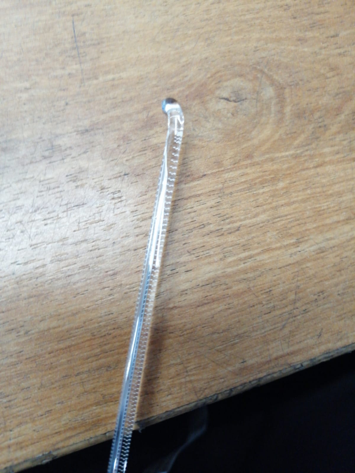
Отправлено спустя 15 минут 57 секунд:
Есть ли на этих аппаратах — fs-1120/1125 фиксатор сканера? Я просто не нашёл, но может он есть 

Kyocera FS-1120mfp ошибка C3100
Сообщение dviz » 20 май 2022, 20:08
Kyocera FS-1120mfp ошибка C3100
Сообщение n_y » 23 май 2022, 09:04
Да, но лампа не светится при старте. Согласно ошибке, нужно проверить: шлейф, форматер либо фиксатор транспортировочный заблокировал скан. головку. Фиксатор я не нашёл. всё остальное заменено. Есть ли там фиксатор? 
Кстати, оптический датчик — так же менял.
В магию не верю, где-то должно быть что-то.

Kyocera FS-1120mfp ошибка C3100
Сообщение перевозчик » 23 май 2022, 09:36
Kyocera FS-1120mfp ошибка C3100
Сообщение n_y » 23 май 2022, 11:38
Kyocera FS-1120mfp ошибка C3100
Сообщение стронций » 23 май 2022, 12:28
Kyocera FS-1120mfp ошибка C3100
Сообщение n_y » 23 май 2022, 12:57
Kyocera FS-1120mfp ошибка C3100
Сообщение стронций » 23 май 2022, 13:14
Kyocera FS-1120mfp ошибка C3100
Сообщение n_y » 23 май 2022, 13:16
Kyocera FS-1120mfp ошибка C3100
Сообщение n_y » 27 май 2022, 18:26
Вопрос такой, что значат значения «O» и «I»? Pulse — Это импульсное значение? Если да, то на контактах 6 и 7 значение 0 и 1,7 соответственно с момента включения до выпадения в ошибку не меняется. на 7 иногда падает до 1,2В (несколько тестов на этом разъёме). Получается, что и 9 — 11 должно подниматься до 6В, но «. что мертво — умереть не может. »
Отправлено спустя 40 минут 8 секунд:
Для чистоты эксперимента подкинул второй форматер, там все также, кроме 9 — 11 На LED control там вообще по 15-16В 

Источник
Kyocera ошибка c3100.
Бывает, что включение мфу Kyocera сопровождается треском и появлением ошибки «c3100 — вызовите сервисный персонал». Наиболее частая причина данной ошибки — не правильный запуск аппарата Kyocera.
Сканер на мфу Kyocera жестко зафиксирован, это делается для того чтобы при транспортировке аппарата не повредить хрупкие элементы сканера. Для устранения ошибки «Machine failure. Call service. C3100» требуется выключить аппарат, и перевести фиксатор в положение «Разблокировать», после этого можно включить мфу Kyocera.

Так же данный фиксатор может находиться сбоку аппарата или же фиксация может быть в виде желтых винтов на боковой крышке аппарата.

Компания Kyomart рекомендует при транспортировки мфу Kyocera зафиксировать сканер, путем переключения фиксатора в положение «Заблокировать», что бы избежать случайных поломок сканера.
Если же на аппарате фиксатор стоит в положении «Разблокировать», а на мфу Kyocera по-прежнему появляется ошибка «c3100 — вызовите сервисный персонал», то возможно неисправен датчик исходного положения каретки, либо неисправен двигатель приводящий в движение каретку сканера.
Если у вас не получается исправить ошибку c3100, то наши специалисты помогут Вам в этом!
Звоните менеджерам компании Kyomart +7 (343) 288-23-45 .
Источник
Ремонт принтеров
рся 3
вторник, 7 ноября 2017 г.
Ошибка C3100 Kyocera
Что делать если при запуске устройства Kyocera на дисплее появилось сообщение об ошибке C3100?
Если при запуске устройства Kyocera Вы увидели на дисплее сообщение: «Machine failure. Call service. C3100» не спешите расстраиваться и звонить в сервисный центр. Эта информация не является сообщением о неисправности или поломке устройства.
Дело в том, что перед транспортировкой копира или МФУ с завода производителя до покупателя, сканирующее устройство на аппаратах Kyocera всегда жёстко фиксируется. Это необходимо для того, чтобы хрупкие элементы сканирующего устройства не повредились при транспортировке.
Фиксаторы закрепляющие сканер могут быть двух типов:
1. Винты с оранжевыми головками (находятся на левой боковой стороне устройства);
2. Оранжевый пластиковый переключатель (находится рядом со стеклом экспонирования под верхней крышкой или реверсивный автоподатчиком
оригиналов);
3. Пластиковая заглушка-фиксатор (находится рядом со стеклом экспонирования под верхней крышкой или реверсивный автоподатчиком
оригиналов).
Ошибка C3100 связана с тем, что каретка сканера не может найти свое начальное положение.
Наиболее частая причина ошибки — неправильный запуск машины. При этом инженер забывает разблокировать каретку путем выкручивания желтых транспортных винтов на боковой крышке.
Возможно, отключен разъем датчика/неисправен датчик исходного положения каретки (оптопара на задней левой части рамы сканера) – в этом случае перед появлением ошибки будет треск от каретки «бьющейся в стенку сканера». Либо ненадежный контакт в разъеме двигателя сканера/неисправен двигатель – в этом случае каретка не двигается после включения вообще.
Все из-за того, что сканер на новых аппаратах любых производителей всегда жестко зафиксирован. Это делается для того, чтобы хрупкие элементы сканера не повредились при переноске.
Фиксатор находится возле стекла экспонирования и сканирующего элемента. Представляет из себя небольшой пластиковый рычажок и выполняется всегда в яркой раскраске для его лучшего обнаружения.
Достаточно перевести рычажок из фиксирующего в рабочее положение и ошибка C3100 устранится. Ошибка C3100 Kyocera
Источник
 Если с аппаратом Kyocera TASKalfa 1800, Kyocera TASKalfa 2200 произошла проблема, откроется следующий экран с уведомлением.
• Индикатор [Внимание] на панели управления горит или мигает.
• На дисплее сообщений панели управления аппарата появилось сообщение об ошибке.
Если индикатор [Внимание] горит или мигает и на дисплее сообщений панели управления аппарата появилось сообщение об ошибке, проверьте KYOCERA Client Tool или Монитор состояния.
ПРИМЕЧАНИЕ Если индикаторы постоянно горят и мигают не так, как описано выше, вероятно, произошла ошибка службы. Выключите питание, отсоедините шнур питания и вставьте его обратно, после чего включите питание. Это может помочь сбросить ошибку. Если ошибка не исчезает, свяжитесь со своим представителем сервисной службы (тел. в Минске +375 17 291-28-24)
Ниже описаны неполадки, которые не могут быть устранены пользователем
|
Дисплей сообщений |
Описание |
Меры устранения |
|
Бункер отраб тонера перепол. или не уст. |
Бункер для отработанного тонера установлен неправильно |
Установите Бункер для отработанного тонера должным образом |
|
Бункер для отработанного тонера заполнен |
Замените бункер отработанного тонера |
|
|
Встряхните картр. с тонером |
Тонер слежался |
Откройте переднюю крышку аппарата и вытяните контейнер с тонером. Сильно встряхните контейнер с тонером и установите его на место |
|
Вызовите сервисный персонал. |
В аппарате произошла ошибка |
Обратите внимание на код ошибки, отображаемый в дисплее сообщений, и свяжитесь с представителем сервисной службы (тел. в Минске +375 17 291-28-24) |
|
Выньте бумагу с внутреннего лотка |
Извлеките бумагу из внутреннего лотка. Нажмите клавишу [OK], чтобы возобновить печать |
|
|
Добавьте тонер |
Закончился тонер |
Замените контейнер с тонером TK-4105 |
|
Загрузите бумагу в кассету # |
↑↓ (отображается попеременно) |
Загрузите бумагу. Нажмите клавишу [OK] и перейдите к следующему шагу. • Для выбора другого устройства подачи выберите [Выберите бумагу]. • Для печати на бумаге, в настоящее время находящейся в устройстве подачи, выберите [Продолж. без изм.] |
|
Загрузите бумагу в универсальный лоток |
↑↓ (отображается попеременно) |
Загрузите бумагу. Нажмите клавишу [OK] и перейдите к следующему шагу. • Для выбора другого устройства подачи выберите [Выберите бумагу]. • Для печати на бумаге, в настоящее время находящейся в устройстве подачи, выберите [Продолж. без изм.] |
|
Закройте автоподатчик оригиналов |
Открыт автоподатчик оригиналов |
Откройте и закройте автоподатчик оригиналов |
|
Закройте крышку автопод. оригиналов |
Открыта верхняя крышка автоподатчика оригиналов |
Откройте и закройте крышку автоподатчика оригинало |
|
Закройте переднюю крышку |
Открыта передняя крышка |
Откройте и закройте переднюю крышку |
|
Закройте правую крышку # |
Открыта какая-либо крышка |
Откройте и закройте крышку, обозначенную на экране |
|
Замятие бумаги. (DP) |
В автоподатчике произошло замятие бумаги. |
См. Устранение замятия бумаги в Руководстве по эксплуатации и извлеките замятую бумагу |
|
Замените МК |
Необходимо производить замену деталей комплекта техобслуживания MK-4105 (ремкомплекта) каждые 150 000 страниц печати. |
Данная операция должна производиться специалистом. Обратитесь к представителю сервисной службы (тел. в Минске +375 17 291-28-24) |
|
Замятие |
Произошло замятие бумаги в кассете или универсальном лотке |
См. Устранение замятия бумаги и извлеките замятую бумагу |
|
Извлеките оригиналы из автоподатчика |
Для продолжения работы необходимо извлечь оригиналы из автоподатчика оригиналов |
Извлеките оригиналы из автоподатчика оригиналов |
|
Кабель USB был отключен |
Кабель USB не подключен |
Нажмите клавишу [OK] и подключите кабель USB |
|
ПК выключен |
Нажмите клавишу [OK] и включите ПК |
|
|
Не удается найти KYOCERA Client Tool |
Нажмите клавишу [OK] и откройте KYOCERA Client Tool на ПК |
|
|
Макс. к-во сканируемых страниц |
Превышен предел сканирования |
Дальнейшее сканирование невозможно. Задание отменено. Нажмите клавишу [OK] |
|
Мало тонера. (Зам., когда законч.) |
Скоро понадобится заменить контейнер с тонером |
Получите новый контейнер с тонером TK-4105. |
|
Не оригинальный тонер |
Установлен контейнер с тонером не марки Kyocera |
Производитель не несет ответственности за повреждения, вызванные использованием неоригинального тонера. Мы рекомендуем использовать исключительно оригинальные контейнеры с тонером TK-4105. . |
|
Неверный ид. уч. зап. Задание отменено |
Указан неверный идентификатор учетной записи при внешней обработке задания. Задание отменено |
Нажмите клавишу [OK] |
|
Невозможна двусторонняя печать на этой бумаге |
Не возможна печать на бумаге выбранного формата или типа |
Нажмите клавишу [OK] и перейдите к следующему шагу: |
|
Недостаточно памяти. Невозможно начать выполнение задания |
Невозможно начать выполнение задания |
Повторите попытку позже |
|
Ограничено алгоритмом учета заданий(Печать) |
Задание отменено, поскольку его выполнение ограничено функцией учета заданий |
Нажмите клавишу [OK] |
|
Ограничено алгоритмом учета заданий(Сканер) |
Задание отменено, поскольку его выполнение ограничено функцией учета заданий |
Нажмите клавишу [OK] |
|
Очистите сканер |
Произошло загрязнение сканера |
Очистите щелевое стекло с помощью чистящей салфетки, поставляемой вместе с автоподатчиком оригиналов. |
|
Ошибка. Выключить |
— |
Отключите и снова включите аппарат с помощью выключателя питания |
|
Память переполнена |
Невозможно продолжить выполнение задания из-за отсутствия свободной памяти |
Измените разрешение печати с Быстр1200 до 600 dpi. См. Printer Driver User Guide |
|
Память сканера переполнена |
Дальнейшее сканирование невозможно из-за нехватки памяти сканера. |
Для отмены задания нажмите [OK] |
|
Перезагрузка печати. Задание отменено |
Предупреждение. Недостаточно памяти принтера. Задание отменено |
Нажмите клавишу [OK] |
|
Превышено ограничение учета заданий |
Превышено число распечаток из-за ограничения алгоритмом учета заданий. Достигнут предел печати |
Это задание отменено. Нажмите клавишу [OK] |
|
Уст.другую кассету |
Выбрано «Сдвиг» |
Для использования сдвига необходимо загрузить в другой лоток бумагу такого же формата, что и в выбранном устройстве подачи, но в другой ориентации |
|
Установите все оригиналы обратно и нажмите клавишу [Старт]. |
Возникает при печати двусторонних документов в режиме ручной двусторонней печати |
Извлеките оригиналы из автоподатчика оригиналов, расположите их в первоначальном порядке и положите обратно. Нажмите клавишу [OK], чтобы возобновить печать. Для отмены задания нажмите [Стоп] |
|
Установлен неизвестный тонер. ПК |
Региональная спецификация контейнера с тонером не соответствует спецификации аппарата |
Установите оригинальный контейнер с тонером Замените контейнер с тонером TK-4105 |
- Code: C0030
- Description: FAX PWB system error
- Causes: The FAX processing cannot be continued due to the FAX firmware error.
- Remedy: 1 Resetting the main power The FAX PWB does not operate properly. Turn off the power switch and unplug the power plug. After 5s passes, reconnect the power plug and turn on the power switch.
2 Firmware upgrade The firmware is faulty. Reinstall the FAX firmware.
3 Replacing the FAX PWB The FAX PWB is faulty. Replace the FAX PWB.
- Code: C0060
- Description: Engine PWB communication error
- Causes: Error was detected at the initial communication of the Engine PWB
- Remedy: 1 Resetting the main power The Engine PWB does not operate properly. Turn off the power switch and unplug the power plug. After 5s passes, reconnect the power plug and turn on the power switch.
2 Checking the connection The connector is not properly connected. Clean the connector (YC12) terminal on the Engine PWB and re-insert the connector
3 Replacing the Engine PWB The Engine PWB is faulty. Replace the Engine PWB.
- Code: C0070
- Description: FAX PWB incompatible detection error
- Causes: Abnormal detection of FAX control PWB incompatibility in the initial communication with the FAX control PWB, any normal communication command is not transmitted.
- Remedy: 1 Checking the FAX PWB The incompatible FAX PWB is installed. Install the FAX PWB for the applicable model.
2 Firmware upgrade The FAX firmware is faulty. Reinstall the FAX firmware.
3 Replacing the main PWB The main PWB is faulty. Replace the main PWB.
- Code: C0100
- Description: Backup memory device error
- Causes: An abnormal status is output from the flash memory.
- Remedy: 1 Resetting the main power The flash memory does not operate properly. Turn off the power switch and unplug the power plug. After 5s passes, reconnect the power plug and turn on the power switch.
2 Checking the main PWB The connector or the FFC is not connected properly. Or, the wire, FFC, the PWB is faulty. Clean the terminal of the connectors on the main PWB, reconnect the connector of the wire, and reconnect the FFC terminal. If the wire or the FFC is faulty, repair or replace them. If not resolved, replace the main PWB.
- Code: C0120
- Description: MAC address data error
- Causes: The MAC address data is incorrect.
- Remedy: 1 Resetting the main power The flash memory does not operate properly. Turn off the power switch and unplug the power plug. After 5s passes, reconnect the power plug and turn on the power switch.
2 Checking the MAC address The MAC address is incorrect. Replace the main PWB when the MAC address is not indicated on the network status page.
- Code: C0130
- Description: Backup memory reading/writing error
- Causes: The reading or writing into the flash memory is unavailable.
- Remedy: 1 Resetting the main power The flash memory does not operate properly. Turn off the power switch and unplug the power plug. After 5s passes, reconnect the power plug and turn on the power switch.
2 Checking the main PWB The connector or the FFC is not connected properly. Or, the wire, FFC, the PWB is faulty. Clean the terminal of the connectors on the main PWB, reconnect the connector of the wire, and reconnect the FFC terminal. If the wire or the FFC is faulty, repair or replace them. If not resolved, replace the main PWB.
- Code: C0140
- Description: Backup memory data error
- Causes: The flash memory data read at the initial start-up is faulty
- Remedy: 1 Resetting the main power The flash memory does not operate properly. Turn off the power switch and unplug the power plug. After 5s passes, reconnect the power plug and turn on the power switch.
2 Checking the main PWB The connector or the FFC is not connected properly. Or, the wire, FFC, the PWB is faulty. Clean the terminal of the connectors on the main PWB, reconnect the connector of the wire, and reconnect the FFC terminal. If the wire or the FFC is faulty, repair or replace them. If not resolved, replace the main PWB.
- Code: C0150
- Description: Engine EEPROM reading / writing error
- Causes: 1. Continuous five times detection of no response from the device for 5ms or more on reading / writing.
2. Data read twice do not match continuous 8 times.
3. Writing data and reading data do not match continuous 8 times. - Remedy: 1 Resetting the main power The EEPROM on the Engine PWB does not operate properly. Turn off the power switch and unplug the power plug. After 5s passes, reconnect the power plug and turn on the power switch.
2 Checking the EEPROM on the Engine PWB The EEPROM is not properly attached. Reattach the EEPROM on the Engine PWB.
3 Replacing the EEPROM The EEPROM is faulty. 1. Print Maintenance Report at U000 beforehand. 2. Replace the EEPROM on the Engine PWB. C0180 appears when turning the power on. Execute U004 at that state. 3. Then, print Maintenance Report at U000. Compare the setting values with Maintenance Report printed before and change the different values. (Target maintenance mode: U051, U065, U067, U100, U101, U161, etc.)
4. Check the output image and adjust the image at U410, etc. if necessary. 4 Replacing the Engine PWB The Engine PWB is faulty. Replace the Engine PWB.
- Code: C0160
- Description: EEPROM data error
- Causes: The data read from the EEPROM is judged as abnormal.
- Remedy: 1 Resetting the main power The EEPROM on the Engine PWB does not operate properly. Turn off the power switch and unplug the power plug. After 5s passes, reconnect the power plug and turn on the power switch.
2 Executing U021 The storage data in the EEPROM on the Engine PWB is faulty. Execute U021.
3 Replacing the EEPROM The EEPROM is faulty. 1. Print Maintenance Report at U000 beforehand. 2. Replace the EEPROM on the Engine PWB. C0180 appears when turning the power on. Execute U004 at that state. 3. Then, print Maintenance Report at U000. Compare the setting values with Maintenance Report printed before and change the different values. (Target maintenance mode: U051, U065, U067, U100, U101, U161, etc.) 4. Check the output image and adjust the image at U410, etc. if necessary.
4 Replacing the Engine PWB The Engine PWB is faulty. Replace the Engine PWB.
- Code: C0170
- Description: Charger count error
- Causes: 1. Errors are detected in both backup memory of the Engine PWB charge counter and main PWB charge counter.
2. Main PWB counter data and Engine PWB counter date are faulty - Remedy: 1 Replacing the main PWB The main PWB is faulty. Replace the main PWB and execute U004
2 Replacing the EEPROM on the Engine PWB The EEPROM is faulty. 1. Print Maintenance Report at U000 beforehand. 2. Replace the EEPROM on the Engine PWB. C0180 appears when turning the power on. Execute U004 at that state. 3. Then, print Maintenance Report at U000. Compare the setting values with Maintenance Report printed before and change the different values. (Target maintenance mode: U051, U065, U067, U100, U101, U161, etc.) 4. Check the output image and adjust the image at U410, etc. if necessary.
3 Replacing the Engine PWB The Engine PWB is faulty. Replace the Engine PWB.
- Code: C0180
- Description: Machine serial number mismatch
- Causes: The machine serial Nos. in the main PWB and the EEPROM on the Engine PWB mismatch when turning the power on.
- Remedy: 1 Checking the machine serial No. of the main PWB The main PWB for the different main unit is installed. Check the machine serial Nos of MAIN and Engine at U004, and install the correct main PWB if the MAIN No. differs.
2 Checking the machine serial No. in the EEPROM on the Engine PWB The EEPROM for the different main unit is installed. Check the machine serial Nos of MAIN and Engine at U004, and install the correct EEPROM on the Engine PWB if the Engine machine serial No. differs.
3 Replacing the main PWB The main PWB is faulty. When the MAIN machine serial No. differs at U004, replace the main PWB and execute U004.
4 Checking the EEPROM on the Engine PWB The EEPROM is faulty. If the machine serial number on the Engine PWB is different at U004, reattach the EEPROM. If not repaired, replace the EEPROM on the Engine PWB. 1. Print Maintenance Report at U000 beforehand. 2. Replace the EEPROM on the Engine PWB. C0180 appears when turning the power on. Execute U004 at that state. 3. Then, print Maintenance Report at U000. Compare the setting values with Maintenance Report printed before and change the different values. (Target maintenance mode: U051, U065, U067, U100, U101, U161, etc.) 4. Check the output image and adjust the image at U410, etc. if necessary.
5 Replacing the Engine PWB The Engine PWB is faulty. Replace the Engine PWB.
- Code: C0190
- Description: Backup memory device error (Engine)
- Causes: Data from the main unit IC cannot be read out at power-up
- Remedy: 1 Resetting the main power The IC in the Engine PWB does not operate normally Turn off the power switch and unplug the power plug. After 5s passes, reconnect the power plug and turn on the power switch.
2 Replacing the Engine PWB The Engine PWB is faulty. Replace the Engine PWB.
- Code: C0500
- Description: Drive lock detected by the Engine firmware
- Causes: During the Engine steady state control, the main motor drive continued 60 minutes or more (except during the maintenance mode)
- Remedy: 1 Resetting the main power The firmware in the Engine PWB does not operate normally Turn off the power switch and unplug the power plug. After 5s passes, reconnect the power plug and turn on the power switch.
2 Replacing the Engine PWB The Engine PWB is faulty. Replace the Engine PWB.
- Code: C0510
- Description: High-voltage remote control error
- Causes: Only the high-voltage remote signal turns on while the drum is stopped
- Remedy: 1 Resetting the main power The firmware in the Engine PWB does not operate normally Turn off the power switch and unplug the power plug. After 5s passes, reconnect the power plug and turn on the power switch.
2 Replacing the Engine PWB The Engine PWB is faulty. Replace the Engine PWB.
- Code: C0520
- Description: Developer control error
- Causes: The developer bias off is detected during the main charge bias off
- Remedy: 1 Resetting the main power The firmware in the Engine PWB does not operate normally Turn off the power switch and unplug the power plug. After 5s passes, reconnect the power plug and turn on the power switch.
2 Replacing the Engine PWB The Engine PWB is faulty. Replace the Engine PWB.
- Code: C0530
- Description: Backup task error
- Causes: No operation 30s or more when monitoring the backup task operation
- Remedy: 1 Resetting the main power The firmware in the Engine PWB does not operate normally Turn off the power switch and unplug the power plug. After 5s passes, reconnect the power plug and turn on the power switch.
2 Replacing the Engine PWB The Engine PWB is faulty. Replace the Engine PWB.
- Code: C0540
- Description: Engine firmware unexpected control detection
- Causes: Eject switching solenoid turned on over the specified time
- Remedy: 1 Resetting the main power The firmware in the Engine PWB does not operate normally Turn off the power switch and unplug the power plug. After 5s passes, reconnect the power plug and turn on the power switch.
2 Replacing the Engine PWB The Engine PWB is faulty. Replace the Engine PWB.
- Code: C0800
- Description: Image processing error
- Causes: The print sequence jam (J010x) is detected 2 times continuously.
- Remedy: 1 Checking the image data The image data is faulty. When this issue occurs only when handling the certain image data, check if the image data is faulty.
2 Checking the situation The printing operation of the certain file is faulty. Acquire the job’s log if the phenomenon can be reproduced by specifying the job when the error was detected.
3 Checking the main PWB The connector or the FFC is not connected properly. Or, the wire, FFC, the PWB is faulty. Clean the terminal of the connectors on the main PWB, reconnect the connector of the wire, and reconnect the FFC terminal. If the wire or the FFC is faulty, repair or replace them. If not resolved, replace the main PWB.
- Code: C0830
- Description: FAX PWB flash program area checksum error
- Causes: The program stored in the flash memory on the FAX PWB is broken so it cannot perform.
- Remedy: 1 Resetting the main power The FAX PWB is not connected properly. Turn off the power switch and pull out the power plug. After passing 5s, reattach the FAX PWB and reinsert the power plug. Then, turn on the power switch.
2 Firmware upgrade The firmware is faulty. Reinstall the FAX firmware.
3 Initializing the fax The data in the FAX PWB is faulty. Execute U600 to initialize the FAX.
4 Replacing the FAX PWB The FAX PWB is faulty. Replace the FAX PWB.
- Code: C0840
- Description: RTC error
- Causes: • Not communicated with RTC correctly. • RTC data is inconsistent with empty battery.
- Remedy: 1 Setting time and date (RTC) Time and date (RTC) are erased Set Date and Time (RTC) from System Menu
2 Replacing the main PWB The main PWB is faulty, or the backup battery runs out. Replacing the main PWB [
- Code: C0870
- Description: PC FAX Image data transmission error
- Causes: Data was not properly transmitted even if the specified times of retry were made when the large volume data is transmitted between the FAX PWB and the main PWB.
- Remedy: 1 Resetting the main power The FAX PWB does not operate properly. Turn off the power switch and pull out the power plug. After passing 5s, reattach the FAX PWB and reinsert the power plug. Then, turn on the power switch.
2 Initializing the fax The data in the FAX PWB is faulty. Execute U600 to initialize the FAX.
3 Firmware upgrade The FAX firmware is faulty. Upgrade the fax firmware to the latest version.
4 Replacing the FAX PWB The FAX PWB is faulty. Replace the FAX PWB.
5 Replacing the main PWB The main PWB is faulty. Replace the main PWB.
- Code: C0920
- Description: FAX file system error
- Causes: The backup data could not be stored since the file system of the flash memory is faulty.
- Remedy: 1 Resetting the main power The FAX PWB does not operate properly. Turn off the power switch and pull out the power plug. After passing 5s, reattach the FAX PWB and reinsert the power plug. Then, turn on the power switch.
2 Initializing the fax FAX control values are incorrect Execute U600 to initialize the FAX.
3 Reconnecting the FAX PWB The FAX PWB is not connected properly. Reinstall FAX PWB to Main PWB.
4 Firmware upgrade The firmware is faulty. Reinstall the FAX firmware.
5 Replacing the FAX PWB The FAX PWB is faulty. Replace the FAX PWB.
- Code: C0980
- Description: 24V power interruption detection
- Causes: • 24V power shutoff signal is detected 1s continuously. • Other service call error occurs after 24V power shutoff signal is lowered, and then 24V power is recovered.
- Remedy: 1 Resetting the main power The firmware in the Engine PWB does not operate normally Turn off the power switch and unplug the power plug. After 5s passes, reconnect the power plug and turn on the power switch.
2 Checking the connection The connector is not connected properly, or the wire is faulty. Clean the terminal of the following wire connectors and reconnect the connectors. If there is no continuity, replace the wire. • Low voltage PWB — Engine PWB
3 Replacing the low voltage PWB The low voltage PWB is faulty. When the +24V generation from the low voltage PWB is not stable, and it lowers, replace the low voltage PWB.
4 Replacing the Engine PWB The Engine PWB is faulty. Replace the Engine PWB.
- Code: C1010
- Description: Lift motor 1 error
- Causes: • Cassette 1 lift motor over-current is detected 5 times continuously. • Lift sensor on is not detected 5 times continuously when passing 15s after cassette 1 is loaded.
- Remedy: 1 Checking the lift plate The lift plate does not operate properly. Repair or replace the lift plate when it does not move vertically.
2 Checking the connection The connector is not connected properly, or the wire is faulty. Clean the terminal of the following wire connectors and reconnect the connectors. If there is no continuity, replace the wire. • Lift motor — Engine PWB (YC18) • Lift sensor — Engine PWB (YC19)
3 Checking the lift motor The lift motor is faulty. Check the lift motor operation, and replace it if necessary.
4 Checking the lift sensor The lift sensor is not properly attached, or it is faulty. Reattach PF lift upper limit sensor. If not repaired, replace it.
5 Firmware upgrade The firmware is not the latest version. Upgrade the Engine firmware to the latest version
6 Replacing the Engine PWB The Engine PWB is faulty. Replace the Engine PWB.
- Code: C1020
- Description: PF lift motor 1 error Object: 500-sheet paper feeder, 500-sheetx2 paper feeder
- Causes: The PF lift sensor 1 on is not detected 5 times continuously when passing 15s after loading cassette 2.
- Remedy: 1 Checking the lift plate The lift plate does not operate properly. Repair or replace the lift plate when it does not move vertically.
2 Checking the connection The connector is not connected properly, or the wire is faulty. Clean the terminal of the following wire connectors and reconnect the connectors. If there is no continuity, replace the wire. • PF lift moor 1 — PF PWB (YC4) • PF upper limit sensor 1 — PF PWB (YC3)
3 Checking PF lift motor 1 PF lift motor 1 is faulty. Check the operation of lift motor 1, and replace it if necessary.
4 Checking PF lift sensor 1 PF lift sensor 1 is not properly attached, or it is faulty. Reattach PF lift sensor 1. If not repaired, replace it.
5 PF firmware upgrade The PF firmware is not the latest version. Upgrade the PF firmware to the latest version.
6 Replacing the PF PWB The PF PWB is faulty. Replace the PF PWB.
- Code: C1030
- Description: PF lift motor 2 error Object: 500-sheetx2 paper feeder
- Causes: The PF lift sensor 2 on is not detected 5 times continuously when passing 15s after loading cassette 3.
- Remedy: 1 Checking the lift plate The lift plate does not operate properly. Repair or replace the lift plate when it does not move vertically.
2 Checking the connection The connector is not connected properly, or the wire is faulty. Clean the terminal of the following wire connectors and reconnect the connectors. If there is no continuity, replace the wire. • PF lift moor 2 — PF PWB (YC6) • PF upper limit sensor 2 — PF PWB (YC5)
3 Checking PF lift motor 2 PF lift motor 2 is faulty. Check the operation of lift motor 2, and replace it if necessary.
4 Checking PF lift sensor 2 PF lift sensor 2 is not properly attached, or it is faulty. Reattach PF lift sensor 2. If not repaired, replace it.
5 PF firmware upgrade The PF firmware is not the latest version. Upgrade the PF firmware to the latest version.
6 Replacing the PF PWB The PF PWB is faulty. Replace the PF PWB.
- Code: C1800
- Description: Paper Feeder communication error Object: 500-sheet paper feeder, 500-sheetx2 paper feeder
- Causes: The communication error was detected 10 times continuously.
- Remedy: 1 Checking the connection The connector is not connected properly, or the wire is faulty. Clean the terminal of the following wire connectors and reconnect the connectors. If there is no continuity, replace the wire. • Engine PWB (YC6) — PF PWB (YC1)
2 Firmware upgrade The firmware is not the latest version. Upgrade the Engine firmware and PF firmware to the latest version
3 Replacing the PF PWB The PF PWB is faulty. Replace the PF PWB.
4 Replacing the Engine PWB The Engine PWB is faulty. Replace the Engine PWB.
- Code: C1900
- Description: Paper Feeder EEPROM error Object: 500-sheet paper feeder, 500-sheetx2 paper feeder For internal count
- Causes: The writing data and the reading data mismatch 4 times continuously when writing.
- Remedy: 1 Checking the connection The connector is not connected properly, or the wire is faulty. Clean the terminal of the following wire connectors and reconnect the connectors. If there is no continuity, replace the wire. • Engine PWB (YC6) — PF PWB (YC1)
2 Firmware upgrade The firmware is not the latest version. Upgrade the Engine firmware and PF firmware to the latest version
3 Replacing the PF PWB The PF PWB is faulty. Replace the PF PWB.
4 Replacing the Engine PWB The Engine PWB is faulty. Replace the Engine PWB.
- Code: C2000
- Description: Main motor steady state error
- Causes: The main motor steady state off is detected 1s continuously after becoming the steady state
- Remedy: 1 Checking the main motor The main motor drive is faulty Execute U030 [Main] and check the main motor operation. Check if the gear rotates or load is heavy in excess
2 Checking the connection The connector is not connected properly, or the wire is faulty. Clean the terminal of the following wire connectors and reconnect the connectors. If there is no continuity, replace the wire. • Main motor — Engine PWB (YC24)
3 Firmware upgrade The firmware is not the latest version. Upgrade the Engine firmware to the latest version
4 Replacing the main motor The main motor is faulty. Replace the main motor.
5 Replacing the Engine PWB The Engine PWB is faulty. Replace the Engine PWB.
- Code: C2010
- Description: Main motor startup error
- Causes: The main motor is not in the steady state within 3s after start-up
- Remedy: 1 Checking the main motor The main motor drive is faulty Execute U030 [Main] and check the main motor operation. Check if the gear rotates or load is heavy in excess
2 Checking the connection The connector is not connected properly, or the wire is faulty. Clean the terminal of the following wire connectors and reconnect the connectors. If there is no continuity, replace the wire. • Main motor — Engine PWB (YC24)
3 Firmware upgrade The firmware is not the latest version. Upgrade the Engine firmware to the latest version
4 Replacing the main motor The main motor is faulty. Replace the main motor.
5 Replacing the Engine PWB The Engine PWB is faulty. Replace the Engine PWB.
- Code: C2101
- Description: Developer motor steady state error
- Causes: Developer motor steady state off is detected 1s continuously after the steady state
- Remedy: 1 Checking the developer motor The developer motor drive is faulty. Execute U030 [DLP] and check the developer motor operation. Check if the gears in the drive unit rotate and there is heavy load in excess.
2 Checking the connection The connector is not connected properly, or the wire is faulty. Clean the terminal of the following wire connectors and reconnect the connectors. If there is no continuity, replace the wire. • Developer motor — Engine PWB (YC25)
3 Firmware upgrade The firmware is not the latest version. Upgrade the Engine firmware to the latest version
4 Replacing the developer motor The developer motor is faulty. Replace the developer motor.
5 Replacing the Engine PWB The Engine PWB is faulty. Replace the Engine PWB.
- Code: C2111
- Description: Developer motor start-up error
- Causes: Developer motor is not in the steady state within 3s after start-up
- Remedy: 1 Checking the developer motor The developer motor drive is faulty. Execute U030 [DLP] and check the developer motor operation. Check if the gears in the drive unit rotate and there is heavy load in excess.
2 Checking the connection The connector is not connected properly, or the wire is faulty. Clean the terminal of the following wire connectors and reconnect the connectors. If there is no continuity, replace the wire. • Developer motor — Engine PWB (YC25)
3 Firmware upgrade The firmware is not the latest version. Upgrade the Engine firmware to the latest version
4 Replacing the developer motor The developer motor is faulty. Replace the developer motor.
5 Replacing the Engine PWB The Engine PWB is faulty. Replace the Engine PWB.
- Code: C2300
- Description: Fuser motor steady state error
- Causes: The fuser motor steady state off is detected 1s continuously after becoming steady state
- Remedy: 1 Checking the fuser motor The fuser motor drive is faulty Execute U030 [Fuser] and check the fuser motor operation. Check if the gears in the drive unit rotate and there is heavy load in excess.
2 Checking the connection The connector is not connected properly, or the wire is faulty. Clean the terminal of the following wire connectors and reconnect the connectors. If there is no continuity, replace the wire. • Fuser motor — Engine PWB(YC24)
3 Firmware upgrade The firmware is not the latest version. Upgrade the Engine firmware to the latest version
4 Replacing the fuser motor The fuser motor is faulty. Replace the fuser motor.
5 Replacing the Engine PWB The Engine PWB is faulty. Replace the Engine PWB.
- Code: C2310
- Description: Fuser motor start-up error
- Causes: The fuser motor is not in the steady state within 3s after start-up
- Remedy: 1 Checking the fuser motor The fuser motor drive is faulty Execute U030 [Fuser] and check the fuser motor operation. Check if the gears in the drive unit rotate and there is heavy load in excess.
2 Checking the connection The connector is not connected properly, or the wire is faulty. Clean the terminal of the following wire connectors and reconnect the connectors. If there is no continuity, replace the wire. • Fuser motor — Engine PWB(YC24)
3 Firmware upgrade The firmware is not the latest version. Upgrade the Engine firmware to the latest version
4 Replacing the fuser motor The fuser motor is faulty. Replace the fuser motor.
5 Replacing the Engine PWB The Engine PWB is faulty. Replace the Engine PWB.
- Code: C2600
- Description: PF motor error Object: 500-sheet paper feeder, 500-sheetx2 paper feeder
- Causes: An error signal was detected 2s continuously during the PF motor drive
- Remedy: 1 Checking the connection The connector is not connected properly, or the wire is faulty. Clean the terminal of the following wire connectors and reconnect the connectors. If there is no continuity, replace the wire. • PF motor — PFPWB (YC2)
2 Firmware upgrade The firmware is not the latest version. Upgrade the PF firmware to the latest version.
3 Checking the PF motor The PF motor is faulty Replace the PF motor
4 Replacing the PF PWB The PF PWB is faulty. Replace the PF PWB.
- Code: C3100
- Description: Carriage error Object: CCD model
- Causes: The home position sensor is off and does not turn on when passing the specified time at initialization and it does not turn on at retry once.
- Remedy: 1 Unlocking the primary mirror unit The primary mirror unit is not unlocked. Unlock the primary mirror unit.
2 Checking the scanner and scanner wire A load is applied to the scanner movement. Move the mirror unit manually. If there is heavy load in excess, clean the scanner wire, wire drum, scanner rail, etc.
3 Checking the connection The connector is not connected properly, or the wire is faulty. Clean the terminal of the following wire connectors and reconnect the connectors. If there is no continuity, replace the wire.• Scanner motor — Engine PWB
4 Checking the scanner motor and the belt tension. The scanner motor or belt tension is faulty Reattach the scanner motor and adjust the belt tension. If not repaired, replace the scanner motor.
5 Checking the home position sensor The home position sensor is faulty. Reattach the home position sensor. If not repaired, replace it.
6 Firmware upgrade The firmware is not the latest version. Upgrade the Engine firmware to the latest version
7 Replacing the Engine PWB The Engine PWB is faulty. Replace the Engine PWB.
- Code: C3100
- Description: Carriage error Object: CIS model
- Causes: The home position sensor is off and does not turn on when passing the specified time at initialization and it does not turn on at retry once.
- Remedy: 1 Checking the scanner and ISU shaft A load is applied to the scanner movement. Move the mirror unit manually. If there is heavy load in excess, check the drive belt and clean the ISU shaft.
2 Checking the connection The connector is not connected properly, or the wire is faulty. Clean the terminal of the wire connectors and reconnect the connectors. If there is no continuity, replace the wire. • Scanner motor — Engine PWB
3 Checking the scanner motor The scanner motor is faulty. Reattach the scanner motor. If not repaired, replace it.
4 Checking the home position sensor The home position sensor is faulty. Reattach the home position sensor. If not repaired, replace it.
5 Firmware upgrade The firmware is not the latest version. Upgrade the Engine firmware to the latest version 6 Replacing the Engine PWB The Engine PWB is faulty. Replace the Engine PWB.
- Code: C3200
- Description: LED error Object: CCD model
- Causes: The white reference data retrieved by lighting the lamp at the initial operation is at the specified value or less.
- Remedy: 1 Checking the LED lamp The LED lamp does not light. Check if the LED lamp lights. If it does not light, replace the lamp unit and execute U411 [Table].
2 Checking the connection FFC is not connected properly. Or it is faulty. Clean the FFC terminals of the following FFC and reconnect them. If the FFC terminal is deformed or broken, replace the FFC. • LED drive PWB — Main PWB (YC3003)
3 Replacing the lens unit The CCD PWB is faulty. Replace the lens unit and execute U411.
4 Firmware upgrade The firmware is not the latest version. Upgrade the Engine firmware to the latest version
5 Replacing the Engine PWB The Engine PWB is faulty. Replace the Engine PWB.
- Code: C3200
- Description: CISerror Object: CIS model
- Causes: • The white reference data retrieved by lighting the lamp at the initial operation is lower than the specified value. • The white reference data retrieved by lighting the lamp at the auto table adjustment is lower than the specified value.
- Remedy: 1 Checking the CIS lamp The CIS lamp does not light Check if the CIS lamp turns on. If not, replace the lamp unit and execute U411 [Table]
2 Checking the connection FFC is not connected properly. Or it is faulty. Clean the FFC terminals of the following FFC and reconnect them. If the FFC terminal is deformed or broken, replace the FFC. • CIS PWB — Main PWB (YC3001)
3 Firmware upgrade The firmware is not the latest version. Upgrade the Engine firmware to the latest version
4 Replacing the Engine PWB The Engine PWB is faulty. Replace the Engine PWB.
- Code: C3300
- Description: CCD AGC error Object: CCD model For internal count
- Causes: The white reference data after adjustment is not within the target range
- Remedy: 1 Cleaning the backside of the contact glass The white reference sheet is dirty. Clean the white reference sheet at the backside of the contact glass.
2 Checking the LED lamp The LED lamp is broken. Check if the LED lamp lights. If it does not light, replace the lamp unit and execute U411 [Table].
3 Checking the connection FFC is not connected properly. Or it is faulty. Clean the FFC terminals of the following FFC and reconnect them. If the FFC terminal is deformed or broken, replace the FFC. • LED drive PWB — Main PWB (YC3003)
4 Replacing the lens unit The CCD PWB is faulty. Replace the lens unit and execute U411.
5 Firmware upgrade The firmware is not the latest version. Upgrade the Engine firmware to the latest version
6 Replacing the Engine PWB The Engine PWB is faulty. Replace the Engine PWB.
- Code: C3300
- Description: CIS AGC error Object: CIS model For internal count
- Causes: The white reference data after adjustment is not within the target range
- Remedy: 1 Cleaning the backside of the contact glass The white reference sheet is dirty. Clean the white reference sheet at the backside of the contact glass.
2 Checking the CIS lamp The CIS lamp does not light Check if the CIS lamp turns on. If not, replace the lamp unit and execute U411 [Table]
3 Checking the connection FFC is not connected properly. Or it is faulty. Clean the FFC terminals of the following FFC and reconnect them. If the FFC terminal is deformed or broken, replace the FFC. • CIS PWB — Main PWB (YC3001)
4 Firmware upgrade The firmware is not the latest version. Upgrade the Engine firmware to the latest version
5 Replacing the Engine PWB The Engine PWB is faulty. Replace the Engine PWB.
- Code: C3500
- Description: Scanner AISC communication error
- Causes: Readback values are different 4 times continuously during communication between the scanner and ASIC
- Remedy: 1 Checking the connection FFC is not connected properly. Or it is faulty. Clean the FFC terminals of the following FFC and reconnect them. If the FFC terminal is deformed or broken, replace the FFC. • Main PWB (YC26) — Engine PWB (YC3)
2 Firmware upgrade The firmware is not the latest version. Upgrade the main firmware and the Engine firmware to the latest version.
3 Replacing the Engine PWB The Engine PWB is faulty. Replace the Engine PWB.
4 Replacing the main PWB The main PWB is faulty. Replace the main PWB.
- Code: C3600
- Description: Scanner sequence error
- Causes: • Mail box buffer overflow is detected. • Software sequence error is detected.
- Remedy: 1 Executing U021 The memory operation is faulty. Execute U021 and initialize the backup data
2 Checking the connection FFC is not connected properly. Or it is faulty. Clean the FFC terminals of the following FFC and reconnect them. If the FFC terminal is deformed or broken, replace the FFC. • Main PWB (YC26) — Engine PWB (YC3)
3 Firmware upgrade The firmware is not the latest version. Upgrade the main firmware and the Engine firmware to the latest version.
4 Replacing the Engine PWB The Engine PWB is faulty. Replace the Engine PWB.
5 Replacing the main PWB The main PWB is faulty. Replace the main PWB.
- Code: C4001
- Description: Polygon motor synchronization error
- Causes: The polygon motor does not become steady state when passing 10s after starting the drive
- Remedy: 1 Checking the connection The connector is not connected properly, or the wire is faulty. Clean the terminal of the following wire connectors and reconnect the connectors. If there is no continuity, replace the wire. • Polygon motor — Engine PWB(YC23)
2 Checking the polygon motor The polygon motor does not rotate properly. Check the rotation sound of the polygon motor, and reattach or replace the LSU if it does not rotate properly.
3 Firmware upgrade The firmware is not the latest version. Upgrade the Engine firmware to the latest version
4 Replacing the Engine PWB The Engine PWB is faulty. Replace the Engine PWB.
- Code: C4011
- Description: Polygon motor steady-state error
- Causes: Steady state off is detected 1s continuously after the polygon motor is in the steady state
- Remedy: 1 Checking the connection The connector is not connected properly, or the wire is faulty. Clean the terminal of the following wire connectors and reconnect the connectors. If there is no continuity, replace the wire. • Polygon motor — Engine PWB(YC23)
2 Checking the polygon motor The polygon motor does not rotate properly. Check the rotation sound of the polygon motor, and reattach or replace the LSU if it does not rotate properly.
3 Firmware upgrade The firmware is not the latest version. Upgrade the Engine firmware to the latest version
4 Replacing the Engine PWB The Engine PWB is faulty. Replace the Engine PWB.
- Code: C4101
- Description: BD initialization error
- Causes: BD is not detected within 1s after the polygon motor is in the steady state
- Remedy: 1 Checking the connection The connector is not connected properly, or the wire is faulty. Clean the terminal of the following wire connectors and reconnect the connectors. If there is no continuity, replace the wire. • APC PWB(YC1) — Main PWB(YC24) • Main PWB(YC26) — Engine PWB(YC3)
2 Checking the LSU The APC PWB does not operate normally Reattach or replace the LSU
3 Firmware upgrade The firmware is not the latest version. Upgrade the main firmware and the Engine firmware to the latest version.
4 Replacing the Engine PWB The Engine PWB is faulty. Replace the Engine PWB.
5 Replacing the main PWB The main PWB is faulty. Replace the main PWB.
- Code: C5101
- Description: Main high-voltage error
- Causes: When measuring the rush-in current by changing the Vpp in 3 steps at the Vpp adjustment, the difference between zero current value and the third step current value is 5 or less.
- Remedy: 1 Checking the drum unit and the developer unit The drum or the drum screw does not rotate properly due to the excessive load. Check if the drum or drum screw rotates by manually and if not, replace the drum unit.
2 Checking the main motor The main motor is faulty. Replace the main motor.
3 Checking the main charger unit Since foreign objects adhere to the main charger highvoltage contact, it is deformed or damaged, proper current does not flow. Check the main charger unit high voltage contact. Clean it if foreign objects adhere. Replace the main charger unit if deformed or damaged and clear the main charger roller counter at U930.
4 Checking the connection FFC is not connected properly. Or it is faulty. Clean the FFC terminals of the following FFC and reconnect them. If the FFC terminal is deformed or broken, replace the FFC. • high voltage PWB — Engine PWB (YC10)
5 Checking the high-voltage PWB The high-voltage PWB is faulty. Replace the high-voltage PWB.
6 Firmware upgrade The firmware is not the latest version. Upgrade the Engine firmware to the latest version
7 Replacing the Engine PWB The Engine PWB is faulty. Replace the Engine PWB.
- Code: C6000
- Description: Fuser main heater broken wire
- Causes: 1. The fuser thermopile does not detect 100°C/212°F within 20s after starting warm-up.
2. During warm-up, the temperature detected by the fuser thermistor does reach the edge ready temperature within 60s after detecting 100°C/212°F. - Remedy: 1 Reinstalling the fuser unit There are foreign objects in the drawer contact terminal of the fuser unit Clean the drawer connector terminal of the fuser unit. Check if the pin of the drawer connector is not bent, and replace the fuser unit if it is bent. If it is normal, reinstall the fuser unit so that the drawer connector is securely connected.
2 Checking the connection The connector is not connected properly, or the wire is faulty. Clean the wire connector terminal and reconnect it. If there is no continuity, replace the wire. • Fuser heater — Low-voltage PWB (YC4) • Thermal cutout — Low-voltage PWB (TB3) • Fuser thermopile — Engine PWB (YC13)
3 Replacing the fuser thermopile The fuser thermopile does not detect temperature correctly Replace the fuser thermopile.
4 Replacing the fuser unit The fuser heater, thermal cutout or others is faulty Replace the fuser unit.
5 Replacing the low voltage PWB The low voltage PWB is faulty. Replace the low voltage PWB.
6 Firmware upgrade The firmware is not the latest version. Upgrade the Engine firmware to the latest version
7 Replacing the Engine PWB The Engine PWB is faulty. Replace the Engine PWB.
- Code: C6020
- Description: Fuser thermopile error
- Causes: The fuser thermopile detects high temperature 1s continuously
- Remedy: 1 Checking the connection The connector is not connected properly, or the wire is faulty. Clean the terminal of the following wire connectors and reconnect the connectors. If there is no continuity, replace the wire. • Fuser thermopile — Engine PWB (YC13)
2 Replacing the fuser thermopile The fuser thermopile does not detect temperature correctly Replace the fuser thermopile.
3 Replacing the low voltage PWB The low voltage PWB is faulty. Replace the low voltage PWB.
4 Firmware upgrade The firmware is not the latest version. Upgrade the Engine firmware to the latest version
5 Replacing the Engine PWB The Engine PWB is faulty. Replace the Engine PWB.
- Code: C6030
- Description: Fuser thermopile wire break detection
- Causes: 1. During warm-up, the fuser thermopile detected the abnormal outer temperature output value for 1s.
2. During warm-up, the fuser thermopile detected the abnormal target output value for 1s. - Remedy: 1 Checking the connection The connector is not connected properly, or the wire is faulty. Clean the terminal of the following wire connectors and reconnect the connectors. If there is no continuity, replace the wire. • Fuser thermopile — Engine PWB (YC13)
2 Replacing the fuser thermopile The fuser thermopile is faulty Replace the fuser thermopile.
3 Firmware upgrade The firmware is not the latest version. Upgrade the Engine firmware to the latest version
4 Replacing the Engine PWB The Engine PWB is faulty. Replace the Engine PWB.
- Code: C6050
- Description: Fuser thermopile low temperature error
- Causes: The fuser thermopile detected 100°C/212°F or less 1s continuously during printing
- Remedy: 1 Checking the connection The connector is not connected properly, or the wire is faulty. Clean the terminal of the following wire connectors and reconnect the connectors. If there is no continuity, replace the wire. • Fuser thermopile — Engine PWB (YC13)
2 Replacing the fuser thermopile The fuser thermopile does not detect temperature correctly Replace the fuser thermopile.
3 Replacing the low voltage PWB The low voltage PWB is faulty. Replace the low voltage PWB.
4 Firmware upgrade The firmware is not the latest version. Upgrade the Engine firmware to the latest version
5 Replacing the Engine PWB The Engine PWB is faulty. Replace the Engine PWB.
- Code: C6200
- Description: Broken fuser sub heater
- Causes: 1. During warm-up, the temperature detected by the fuser thermistor does not reach 100°C/212°F within 60s after starting warm-up.
2. During warm-up, the temperature detected by the fuser thermistor does not reach the edge ready temperature within 60s after detecting 100°C/212°F. - Remedy: 1 Reinstalling the fuser unit There are foreign objects in the drawer contact terminal of the fuser unit Clean the drawer connector terminal of the fuser unit. Check if the pin of the drawer connector is not bent, and replace the fuser unit if it is bent. If it is normal, reinstall the fuser unit so that the drawer connector is securely connected.
2 Checking the connection The connector is not connected properly, or the wire is faulty. Clean the wire connector terminal and reconnect it. If there is no continuity, replace the wire. • Fuser heater — Low-voltage PWB (YC4) • Thermal cutout — Low-voltage PWB (TB3) • Fuser thermistor — Engine PWB (YC13)
3 Replacing the fuser unit The fuser sub heater, fuser thermistor, or others is faulty Replace the fuser unit.
4 Replacing the low voltage PWB The low voltage PWB is faulty. Replace the low voltage PWB.
5 Firmware upgrade The firmware is not the latest version. Upgrade the Engine firmware to the latest version
6 Replacing the Engine PWB The Engine PWB is faulty. Replace the Engine PWB.
- Code: C6220
- Description: Fuser thermistor high temperature error
- Causes: The fuser thermistor detected high temperature 1s continuously
- Remedy: 1 Reinstalling the fuser unit There are foreign objects in the drawer contact terminal of the fuser unit Clean the drawer connector terminal of the fuser unit. Check if the pin of the drawer connector is not bent, and replace the fuser unit if it is bent. If it is normal, reinstall the fuser unit so that the drawer connector is securely connected.
2 Checking the connection The connector is not connected properly, or the wire is faulty. Clean the wire connector terminal and reconnect it. If there is no continuity, replace the wire. • Fuser heater — Low-voltage PWB (YC4) • Thermal cutout — Low-voltage PWB (TB3) • Fuser thermistor — Engine PWB (YC13)
3 Replacing the fuser unit The fuser thermistor does not detect temperature correctly Replace the fuser unit.
4 Replacing the low voltage PWB The low voltage PWB is faulty. Replace the low voltage PWB.
5 Firmware upgrade The firmware is not the latest version. Upgrade the Engine firmware to the latest version
6 Replacing the Engine PWB The Engine PWB is faulty. Replace the Engine PWB.
- Code: C6230
- Description: Broken fuser thermistor detection
- Causes: The fuser thermistor detects 42°C/108°F or less while the fuser thermopile detects 100°C/212°F or more during warmup
- Remedy: 1 Reinstalling the fuser unit There are foreign objects in the drawer contact terminal of the fuser unit Clean the drawer connector terminal of the fuser unit. Check if the pin of the drawer connector is not bent, and replace the fuser unit if it is bent. If it is normal, reinstall the fuser unit so that the drawer connector is securely connected.
2 Checking the connection The connector is not connected properly, or the wire is faulty. Clean the wire connector terminal and reconnect it. If there is no continuity, replace the wire. • Fuser heater — Low-voltage PWB (YC4) • Thermal cutout — Low-voltage PWB (TB3) • Fuser thermistor — Engine PWB (YC13)
3 Replacing the fuser unit The fuser thermistor is faulty Replace the fuser unit.
4 Firmware upgrade The firmware is not the latest version. Upgrade the Engine firmware to the latest version
5 Replacing the Engine PWB The Engine PWB is faulty. Replace the Engine PWB.
- Code: C6250
- Description: Fuser thermistor low temperature error
- Causes: The fuser thermistor detected 60 degree C or less 1s continuously during printing
- Remedy: 1 Reinstalling the fuser unit There are foreign objects in the drawer contact terminal of the fuser unit Clean the drawer connector terminal of the fuser unit. Check if the pin of the drawer connector is not bent, and replace the fuser unit if it is bent. If it is normal, reinstall the fuser unit so that the drawer connector is securely connected.
2 Checking the connection The connector is not connected properly, or the wire is faulty. Clean the wire connector terminal and reconnect it. If there is no continuity, replace the wire. • Fuser heater — Low-voltage PWB (YC4) • Thermal cutout — Low-voltage PWB (TB3) • Fuser thermistor — Engine PWB (YC13)
3 Replacing the fuser unit The fuser thermistor is faulty Replace the fuser unit.
4 Replacing the low voltage PWB The low voltage PWB is faulty. Replace the low voltage PWB.
5 Firmware upgrade The firmware is not the latest version. Upgrade the Engine firmware to the latest version
6 Replacing the Engine PWB The Engine PWB is faulty. Replace the Engine PWB.
- Code: C6400
- Description: Zero-cross signal error
- Causes: No zero-cross signal continued 3s during the heater control
- Remedy: 1 Checking the connection The connector is not connected properly, or the wire is faulty. Clean the terminal of the following wire connectors and reconnect the connectors. If there is no continuity, replace the wire. • Engine PWB (YC14) — Low-voltage PWB (YC8)
2 Replacing the low voltage PWB The low voltage PWB is faulty. Replace the low voltage PWB.
3 Firmware upgrade The firmware is not the latest version. Upgrade the Engine firmware to the latest version
4 Replacing the Engine PWB The Engine PWB is faulty. Replace the Engine PWB.
- Code: C6610
- Description: Pressure release error
- Causes: 1. The fuser pressure release sensor changing from on to off is not detected when passing 10s after starting the fuser pressure decrease.
2. The fuser pressure release sensor changing from off to on is not detected when passing 10s after starting the fuser pressure increase. - Remedy: 1 Reinstalling the fuser unit There are foreign objects in the drawer contact terminal of the fuser unit Clean the drawer connector terminal of the fuser unit. Check if the pin of the drawer connector is not bent, and replace the fuser unit if it is bent. If it is normal, reinstall the fuser unit so that the drawer connector is securely connected.
2 Checking the connection The connector is not connected properly, or the wire is faulty. Clean the wire connector terminal and reconnect it. If there is no continuity, replace the wire. • Engine PWB (YC21) — Fuser pressure release motor • Engine PWB (YC13) — Fuser pressure release sensor
3 Replacing the fuser unit The fuser unit is faulty at the fuser pressure release mechanism or the fuser pressure release sensor . Replace the fuser unit.
- Code: C6650
- Description: Fuser thermopile EEPROM error
- Causes: 1. Access to the thermopile EEPROM is not available.
2. During scanning, no response from the device is detected 5ms or more 5 times continuously. - Remedy: 1 Checking the connection The connector is not connected properly, or the wire is faulty. Clean the terminal of the following wire connectors and reconnect the connectors. If there is no continuity, replace the wire. • Fuser thermopile — Engine PWB(YC13)
2 Replacing the fuser thermopile The fuser thermopile does not detect temperature correctly Replace the fuser thermopile.
3 Firmware upgrade The firmware is not the latest version. Upgrade the Engine firmware to the latest version
4 Replacing the Engine PWB The Engine PWB is faulty. Replace the Engine PWB.
- Code: C7200
- Description: Inner thermistor broken (developer)
- Causes: The input sampling value of the sensor is at the reference value or more.
- Remedy: 1 Reinstalling the developer unit The developer unit is not properly installed. Reinstall developer unit so that the connector connects securely.
2 Checking the connection The connector is not connected properly, or the wire is faulty. Clean the terminal of the following wire connectors and reconnect the connectors. If there is no continuity, replace the wire. • Developer relay PWB — Engine PWB (YC8)
3 Developer unit replacement The sensor on the developer PWB is faulty Replace the developer unit.
4 Firmware upgrade The firmware is not the latest version. Upgrade the Engine firmware to the latest version
5 Replacing the Engine PWB The Engine PWB is faulty. Replace the Engine PWB.
- Code: C7210
- Description: Inner thermistor short-circuited (developer)
- Causes: The sensor input sampling value is at the reference value or less
- Remedy: 1 Reinstalling the developer unit The developer unit is not properly installed. Reinstall developer unit so that the connector connects securely.
2 Checking the connection The connector is not connected properly, or the wire is faulty. Clean the terminal of the following wire connectors and reconnect the connectors. If there is no continuity, replace the wire. • Developer relay PWB — Engine PWB (YC8)
3 Developer unit replacement The sensor on the developer PWB is faulty Replace the developer unit.
4 Firmware upgrade The firmware is not the latest version. Upgrade the Engine firmware to the latest version 5 Replacing the Engine PWB The Engine PWB is faulty. Replace the Engine PWB.
- Code: C7800
- Description: Outer thermistor broken
- Causes: The input sampling value of the sensor is at the reference value or more.
- Remedy: 1 Checking the connection The connector is not connected properly, or the wire is faulty. Clean the terminal of the wire connectors and reconnect the connectors. If there is no continuity, replace the wire. • Temperature/humidity sensor — Engine PWB (YC9)
2 Replacing the temperature/ humidity sensor The temperature/humidity sensor is faulty. Replace the temperature/humidity sensor.
3 Firmware upgrade The firmware is not the latest version. Upgrade the Engine firmware to the latest version
4 Replacing the Engine PWB The Engine PWB is faulty. Replace the Engine PWB.
- Code: C7810
- Description: Outer thermistor short-circuited
- Causes: The sensor input sampling value is at the reference value or less
- Remedy: 1 Checking the connection The connector is not connected properly, or the wire is faulty. Clean the terminal of the wire connectors and reconnect the connectors. If there is no continuity, replace the wire. • Temperature/humidity sensor — Engine PWB (YC9)
2 Replacing the temperature/ humidity sensor The temperature/humidity sensor is faulty. Replace the temperature/humidity sensor.
3 Firmware upgrade The firmware is not the latest version. Upgrade the Engine firmware to the latest version
4 Replacing the Engine PWB The Engine PWB is faulty. Replace the Engine PWB.
- Code: C8030
- Description: DF tray upper limit detection error Object: 500-sheet document finisher
- Causes: The DF tray upper limit sensor on is detected when the DF tray motor is in ascending operation
- Remedy: 1 Checking the connection The connector is not connected properly, or the wire is faulty. Clean the terminal of the following wire connectors and reconnect the connectors. If there is no continuity, replace the wire. • DF tray upper limit sensor — DFPWB (CN5) • Paper level sensor 1, 2 — DFPWB (CN6)
2 Replacing the sensor The Dr tray upper limit sensor, paper level sensor 1 or 2 is faulty Replace the DF tray upper limit sensor or paper level sensor.
3 Firmware upgrade The firmware is not the latest version. Upgrade the DP firmware to the latest version.
4 Replacing the DF PWB The DF PWB is faulty. Replace the DF PWB.
- Code: C8040
- Description: DF belt error Object: 500-sheet document finisher
- Causes: The DF belt sensor on or off cannot be detected when passing the specified time after the DF belt solenoid turns on
- Remedy: 1 Checking the connection The connector is not connected properly, or the wire is faulty. Clean the wire connector terminal and reconnect it. If there is no continuity, replace the wire. • DF belt sensor — DF PWB (CN10) • DF belt solenoid — DF PWB (CN21)
2 Replacing the DF belt sensor DF belt sensor is faulty Replace DF belt sensor
3 Replacing the DF belt solenoid DF belt solenoid is faulty Replace DF belt solenoid
4 Firmware upgrade The firmware is not the latest version. Upgrade the DP firmware to the latest version.
5 Replacing the DF PWB The DF PWB is faulty. Replace the DF PWB.
- Code: C8140
- Description: Dr tray motor error Object: 500-sheet document finisher
- Causes: During the DF tray motor drive, the DF tray lower limit sensor, paper level sensor 1 and 2 on is not detected within 10s.
- Remedy: 1 Checking the connection The connector is not connected properly, or the wire is faulty. Clean the terminal of the following wire connectors and reconnect the connectors. If there is no continuity, replace the wire. • DF tray motor — DF PWB (CN15) • DF tray lower limit sensor — DF PWB (CN5) • Paper level sensor1, 2 — DF PWB (CN6)
2 Replacing the DF tray motor The DF tray motor is faulty. Replace the DF tray motor.
3 Replacing the sensor The DF tray lower limit sensor, paper level sensor 1 or 2 is faulty Replace the DF tray lower limit sensor or paper level sensor.
4 Firmware upgrade The firmware is not the latest version. Upgrade the DP firmware to the latest version.
5 Replacing the DF PWB The DF PWB is faulty. Replace the DF PWB.
- Code: C8210
- Description: DF staple error Object: 500-sheet document finisher
- Causes: JAM7013 and 7023 was detected twice
- Remedy: 1 Checking the connection The connector is not connected properly, or the wire is faulty. Clean the terminal of the wire connectors and reconnect the connectors. If there is no continuity, replace the wire. • DF staple unit — DF PWB
2 Checking the staple Check if the upper BF registration guide shifts manually, and reattach it if it does not smoothly shift. Check if the lower BF registration guide shifts manually, and reattach it if it does not smoothly shift.
3 Replacing the DF staple unit The DF staple unit is faulty. Replace the DF staple unit.
4 Firmware upgrade The firmware is not the latest version. Upgrade the DP firmware to the latest version.
5 Replacing the DF PWB The DF PWB is faulty. Replace the DF PWB.
- Code: C8320
- Description: DF adjuster motor 2 error Object: 500-sheet document finisher
- Causes: The DF adjusting sensor 2 on or off cannot be detected when passing the specified time after the DF adjusting motor 2 turns on
- Remedy: 1 Checking the connection The connector is not connected properly, or the wire is faulty. Clean the terminal of the following wire connectors and reconnect the connectors. If there is no continuity, replace the wire. • DF adjusting motor 2 — DFPWB (CN18) • DF adjusting sensor
2 — DFPWB (CN7) 2 Replacing DF adjusting motor 2 DF adjusting motor 2 is faulty Replace DF adjusting motor 2
3 Replacing the DF adjusting sensor 2 DF adjusting sensor 2 is faulty Replace DF adjusting sensor 2
4 Firmware upgrade The firmware is not the latest version. Upgrade the DP firmware to the latest version.
5 Replacing the DF PWB The DF PWB is faulty. Replace the DF PWB.
- Code: C8330
- Description: DF adjuster motor 1error Object: 500-sheet document finisher
- Causes: The DF adjusting sensor 1 on or off cannot be detected when passing the specified time after the DF adjusting motor 1 turns on
- Remedy: 1 Checking the connection The connector is not connected properly, or the wire is faulty. Clean the terminal of the following wire connectors and reconnect the connectors. If there is no continuity, replace the wire.• DF adjusting motor 1 — DFPWB(CN18) • DF adjusting sensor 1 — DFPWB(CN7)
2 Replacing DF adjusting motor 1 DF adjusting motor 1 is faulty Replace DF adjusting motor 1
3 Replacing the DF adjusting sensor 1 DF adjusting sensor 1 is faulty Replace DF adjusting sensor 1
4 Firmware upgrade The firmware is not the latest version. Upgrade the DP firmware to the latest version.
5 Replacing the DF PWB The DF PWB is faulty. Replace the DF PWB.
- Code: C8350
- Description: DF roller motor error Object: 500-sheet document finisher
- Causes: The DF roller sensor on or off cannot be detected when passing the specified time after the DF roller motor turns on
- Remedy: 1 Checking the connection The connector is not connected properly, or the wire is faulty. Clean the terminal of the following wire connectors and reconnect the connectors. If there is no continuity, replace the wire. • DF roller motor — DF PWB (CN20) • DF roller sensor — DF PWB (CN11)
2 Replacing the DF roller sensor DF roller sensor is faulty Replace DF roller sensor
3 Replacing the DF roller motor The DF roller motor is faulty Replace DF roller motor 4 Firmware upgrade The firmware is not the latest version. Upgrade the DP firmware to the latest version. 5 Replacing the DF PWB The DF PWB is faulty. Replace the DF PWB.
- Code: C8360
- Description: DF slide motor error Object: 500-sheet document finisher
- Causes: The DF slide sensor on or off cannot be detected when passing the specified time after the DF slide motor turns on
- Remedy: 1 Checking the connection The connector is not connected properly, or the wire is faulty. Clean the terminal of the following wire connectors and reconnect the connectors. If there is no continuity, replace the wire. • DF slide motor — DF PWB(CN14) • DF slide sensor — DF PWB(CN22)
2 Replacing the DF slide sensor The DF slide sensor is faulty. Replace the DF slide sensor
3 Replacing the DF slide motor The DF slide motor is faulty. Replace the DF slide motor
4 Firmware upgrade The firmware is not the latest version. Upgrade the DP firmware to the latest version.
5 Replacing the DF PWB The DF PWB is faulty. Replace the DF PWB.
- Code: C8460
- Description: EEPROM error Object: 500-sheet document finisher
- Causes: EEPROM read/write is not available
- Remedy: 1 Firmware upgrade The firmware is not the latest version. Upgrade the DP firmware to the latest version.
2 Replacing the DF PWB The DF PWB is faulty. Replace the DF PWB.
- Code: C8800
- Description: Document finisher communication error Object: 500-sheet document finisher
- Causes: The communication error was detected 10 times continuously.
- Remedy: 1 Checking the connection The connector is not connected properly, or the wire is faulty. Clean the wire connector terminal and reconnect it. If there is no continuity, replace the wire. • Engine PWB (YC5) — DF relay PWB (YC2) • DF relay PWB (YC3) — DF PWB (CN1)
2 Firmware upgrade The firmware is not the latest version. Upgrade the DP firmware to the latest version.
3 Replacing the DF relay PWB The DF relay PWB is faulty Replace the DF relay PWB.
4 Replacing the DF PWB The DF PWB is faulty. Replace the DF PWB.
5 Firmware upgrade The firmware is not the latest version. Upgrade the Engine firmware to the latest version
6 Replacing the Engine PWB The Engine PWB is faulty. Replace the Engine PWB.
- Code: C8830
- Description: Relay conveying unit communication error Object: 500-sheet document finisher + relay conveying unit
- Causes: The communication error was detected 10 times continuously.
- Remedy: 1 Checking the connection The connector is not connected properly, or the wire is faulty. Clean the terminal of the following wire connectors and reconnect the connectors. If there is no continuity, replace the wire. • Engine PWB (YC5) — DF relay PWB (YC2) • DF relay PWB (YC4) — BR PWB (YC5)
2 Firmware upgrade The firmware is not the latest version. Upgrade the BR firmware to the latest version.
3 Replacing the BR PWB The BR PWB is faulty. Replace the BR PWB.
4 Replacing the DF relay PWB The DF relay PWB is faulty Replace the DF relay PWB.
5 Firmware upgrade The firmware is not the latest version. Upgrade the Engine firmware to the latest version
6 Replacing the Engine PWB The Engine PWB is faulty. Replace the Engine PWB.
- Code: C8990
- Description: Finisher setup error Object: 500-sheet document finisher + relay conveying unit
- Causes: 1. Communication error occurs with either the finisher or relay conveying unit.
2. Communication error occurs while installation of the relay conveying unit is detected - Remedy: 1 Checking the connection The connector is not connected properly, or the wire is faulty. Clean the wire connector terminal and reconnect it. If there is no continuity, replace the wire. • DF PWB (CN1) — DF relay PWB (YC3) • DF relay PWB (YC4) — BR PWB (YC5)
2 Firmware upgrade The firmware is not the latest version. Upgrade the DP firmware to the latest version.
3 Replacing the DF PWB The DF PWB is faulty. Replace the DF PWB.
4 Replacing the BR PWB The BR PWB is faulty. Replace the BR PWB.
- Code: C9000
- Description: DP communication error Object: Document processor
- Causes: The communication error was detected 10 times continuously.
- Remedy: 1 Firmware upgrade The main unit firmware and the document processor firmware mismatch Upgrade the main unit firmware and the document processor firmware to the latest version.
2 Checking the connection The connector is not connected properly, or the wire is faulty. Clean the terminal of the following wire connectors and reconnect the connectors. If there is no continuity, replace the wire. • DP PWB (YC2) — Engine PWB (YC4)
3 Replacing the DP PWB The DP PWB is faulty. Replace the DP PWB.
4 Replacing the Engine PWB The Engine PWB is faulty. Replace the Engine PWB.
- Code: C9060
- Description: DP EEPROM error Object: Document processor
- Causes: The writing data and the reading data into the EEPROM mismatch.
- Remedy: 1 Checking the EEPROM The EEPROM is not properly installed. Reattach the EEPROM on the DP PWB.
2 Replacing the DP PWB The DP PWB is faulty. Replace the DP PWB.
3 Replacing the EEPROM The EEPROM is faulty. Replace the EEPROM on the DP PWB, then execute U411.
- Code: C9180
- Description: DP feed-shift motor error Object: Document processor
- Causes: 1. The DP feed-shift motor home position cannot be detected even driving it for one round.
2. The DP feed-shift motor home position cannot be detected even after retrying the detection for 3 times. - Remedy: 1 Checking the connection The connector is not connected properly, or the wire is faulty. Clean the terminal of the following wire connectors and reconnect the connectors. If there is no continuity, replace the wire. • DP feed-shift motor — DP PWB (YC7) • DP feed-shift sensor — DP PWB (YC4) • DP PWB (YC2) — Engine PWB (YC18)
2 Replacing the DP feed-shift sensor The DP feed-shift sensor is faulty. Replce the DP feed-shift sensor.
3 Replacing the DP feed-shift motor The DP feed-shift motor is faulty. Replace the DP feed-shift motor.
4 Replacing the DP PWB The DP PWB is faulty. Replace the DP PWB.
5 Replacing the Engine PWB The Engine PWB is faulty. Replace the Engine PWB.
- Code: F000
- Description: Main unit CPU communication error (Controller — Panel)
- Causes: The panel cannot be detected since the CPU communication between the main PWB and the operation panel main PWB is unavailable.
- Remedy: 1 Resetting the main power The communication between the main PWB and the operation panel main PWB is faulty. Turn off the power switch and pull out the power plug. After passing 5s, reinsert the power plug and turn on the power switch.
2 Checking the connection The connector is not connected properly. Or, the wire or the SATA cable is faulty. Clean the wire, the terminal of SATA cable connector and reconnect them. If there is no continuity, replace the wire. • Main PWB — Operation panel PWB
3 Executing U021 The backup RAM data is faulty. Execute U021 to initialize the backup RAM data.
4 Replacing the main PWB The main PWB is faulty. Replace the main PWB.
5 Replacing the operation panel main PWB The operation panel main PWB is faulty. Replace the panel main PWB.
- Code: F010
- Description: Program read error
- Causes: Data corruption is detected at the program read
- Remedy: 1 Resetting the main power The communication between the main PWB and the operation panel main PWB is faulty. Turn off the power switch and pull out the power plug. After passing 5s, reinsert the power plug and turn on the power switch.
2 Executing U021 The backup RAM data is faulty. Execute U021 to initialize the backup RAM data.
3 Replacing the main PWB The main PWB is faulty. Replace the main PWB.
- Code: F020
- Description: System memory error (RAM reading/writing error or CPU memory error)
- Causes: The error appears during the reading/writing check of the RAM for the CPU when the main unit starts up.
- Remedy: 1 Resetting the main power The communication between the main PWB and the operation panel main PWB is faulty. Turn off the power switch and pull out the power plug. After passing 5s, reinsert the power plug and turn on the power switch.
2 Executing U021 The backup RAM data is faulty. Execute U021 to initialize the backup RAM data.
3 Checking the main PWB The connector or the FFC is not connected properly. Or, the wire, FFC, the PWB is faulty. Clean the terminal of the connectors on the main PWB, reconnect the connector of the wire, and reconnect the FFC terminal. If the wire or the FFC is faulty, repair or replace them. If not resolved, replace the main PWB.
- Code: F040
- Description: Communication error between the main unit CPU (Communication error between the controller and Engine)
- Causes: There is an error in the communication between the main PWB and the Engine PWB.
- Remedy: 1 Resetting the main power There is an error in the communication between the main PWB and the Engine PWB. Turn off the power switch and pull out the power plug. After passing 5s, reinsert the power plug and turn on the power switch.
2 Checking the connection The connector is not connected properly, or the wire is faulty. Clean the terminal of the following wire connectors and reconnect the connectors. If there is no continuity, replace the wire. • Engine PWB (YC3) — Main PWB (YC26)
3 Firmware upgrade The firmware is not the latest version. Upgrade the main firmware and the Engine firmware to the latest version.
4 Replacing the main PWB The main PWB is faulty. Replace the main PWB.
5 Replacing the Engine PWB The Engine PWB is faulty. Replace the Engine PWB.
- Code: F050
- Description: Engine program error
- Causes: The Engine program cannot start up.
- Remedy: 1 Firmware upgrade The firmware is not the latest version. Upgrade the Engine firmware to the latest version
2 Resetting the main power The Engine firmware checksum is faulty. Turn off the power switch and pull out the power plug. After passing 5s, reinsert the power plug and turn on the power switch.
3 Checking the EEPROM The EEPROM is not properly attached. Reattach the EEPROM.
4 Checking the Engine PWB The connector or the FFC is not connected properly. Or, the wire, FFC, the PWB is faulty. Clean the terminal of the connectors on the Engine PWB, reconnect the connector of the wire, and reconnect the FFC terminal. If the wire or the FFC is faulty, repair or replace it. If not resolved, replace the Engine PWB.
- Code: F052
- Description: Panel Engine program error
- Causes: The panel program cannot start up.
- Remedy: 1 Firmware upgrade The firmware is not the latest version. Upgrade the panel firmware to the latest version.
2 Resetting the main power The panel RAM checksum is faulty. Turn off the power switch and pull out the power plug. After passing 5s, reinsert the power plug and turn on the power switch.
3 Checking the connection The connector is not connected properly, or the wire is faulty. Clean the terminal of the connectors on the operation panel PWB, reconnect the connector of the wire. If there is no continuity, replace the wire.
4 Replacing the operation panel main PWB The operation panel main PWB is faulty. Replace the panel main PWB.
- Code: F12X
- Description: Abnormality detecting in a Scan control section
- Causes:
- Remedy: (1) Check the harness between Scan/DP<=>Main boards, and the connection state of a connector, and perform an operation check. (2) Initialize SSD and perform an operation check. * (3) U021 Controller backup initialization is carried out and an operation check is performed. (4) Exchange a Scan/DP board and perform an operation check. (5) Exchange a Main board and perform an operation check. (6) Get USBLOG and contact service headquarters. * Only SSD standard model
- Code: F14X
- Description: Abnormality detecting in a FAX control part
- Causes:
- Remedy: (1) Check the harness between FAX<=>Main boards, and the connection state of a connector, and perform an operation check. (2) Initialize SSD and perform an operation check. * (3) U021 Controller backup initialization is carried out and an operation check is performed. (4) Perform a deed operation check for DIMM Clear by U671. * Notes(Since it disappears when received data remain, cautions are required.) (5) Exchange FAX_DIMM and perform an operation check. * Notes (6) Exchange a FAX board and perform an operation check. (7) Exchange a Main board and perform an operation check. (8) Get USBLOG and contact service headquarters. * Only SSD standard model * Note Only model which has Flash for FAX data in a Main board
- Code: F15X
- Description: Abnormality detecting in an authentication device control section
- Causes:
- Remedy: (1) Check the harness between authentication device <=>Main boards, and the connection situation of a connector, and perform an operation check. (2) Initialize SSD and perform an operation check. * (3) Carry out U021 Main backup initialization and perform an operation check. (4) Exchange a Main board and perform an operation check. (5) Exchange SSD and perform an operation check. * (6) Get USBLOG and contact service headquarters. * Only SSD standard model
- Code: F17X
- Description: Abnormality detecting in a printer data control part
- Causes:
- Remedy: (1) Initialize SSD and perform an operation check. * (2) Carry out U021 Main backup initialization and perform an operation check. (3) Exchange a Main board and perform an operation check. (4) Exchange SSD and perform an operation check. * (5) Get USBLOG and contact service headquarters. * Only SSD standard model
- Code: F18X
- Description: Abnormality detecting in a Video control section
- Causes:
- Remedy: (1) Check the harness between Engine<=>Main boards, and the connection state of a connector, and perform an operation check. (2) Initialize SSD and perform an operation check. * (3) U021 Controller backup initialization is carried out and an operation check is performed. (4) Exchange an Engine board and perform an operation check. (5) Exchange a Main board and perform an operation check. (6) Get USBLOG and contact service headquarters. * Only SSD standard model
- Code: F1DX
- Description: Abnormality detecting of the image memory Management Department
- Causes: * Poor arrangement of F1D4:Random Access Memory(1) Confirmation of U340(2) Initialization of a set point (U021)
- Remedy: (1) Initialize SSD and perform an operation check. * (2) Carry out U021 Main backup initialization and perform an operation check. (3) Exchange a Main board and perform an operation check. (4) Exchange SSD and perform an operation check. * (5) Get USBLOG and contact service headquarters. * Only SSD standard model
- Code: F21X, F22X, F23X
- Description: Abnormality detecting in an image-processing part
- Causes: * F248 is the abnormalities of a printer process.In recurring by specific printer data, please give me cooperation at acquisition of capture data and USBLOG.
- Remedy: (1) Check contact of a DDR memory and perform an operation check. (2) Initialize SSD and perform an operation check. * (3) Carry out U021 Main backup initialization and perform an operation check. (4) Exchange a Main board and perform an operation check. (5) Exchange SSD and perform an operation check. * (6) Get USBLOG and contact service headquarters. * Only SSD standard model
- Code: F24X
- Description: Abnormality detecting in the system Management Department
- Causes: * F248 is the abnormalities of a printer process.In recurring by specific printer data, please give me cooperation at acquisition of capture data and USBLOG.
- Remedy: (1) Check contact of a DDR memory and perform an operation check. (2) Initialize SSD and perform an operation check. * (3) Carry out U021 Main backup initialization and perform an operation check. (4) Exchange a Main board and perform an operation check. (5) Exchange SSD and perform an operation check.* (6) Get USBLOG and contact service headquarters. * Only SSD standard model
- Code: F25X
- Description: Abnormality detecting in a network management department
- Causes: [Main body to External network] Ethernet connector * It may occur according to a visitor’s networkenvironment.
- Remedy: (1) Initialize SSD and perform an operation check. * (2) Carry out U021 Main backup initialization and perform an operation check. (3) Exchange a Main board and perform an operation check. (4) Get USBLOG and packet capture and contact service headquarters. * Only SSD standard model
- Code: F26X … F2AX
- Description: Abnormality detecting in the system Management Department
- Causes:
- Remedy: (1) Initialize SSD and perform an operation check. * (2) Carry out U021 Main backup initialization and perform an operation check. (3) Exchange a Main board and perform an operation check. (4) Exchange SSD and perform an operation check. * (5) Get USBLOG and contact service headquarters. * Only SSD standard model
- Code: F2BX … F32X
- Description: Abnormality detecting in a network control part
- Causes: [Main body to External network] Ethernet connector
- Remedy: (1) Initialize SSD and perform an operation check. * (2) Carry out U021 Main backup initialization and perform an operation check. (3) Exchange a Main board and perform an operation check. 4) Get USBLOG and contact service headquarters. (Depending on an analysis result, it is packet capture acquisition) * Only SSD standard model
- Code: F33X
- Description: Abnormality detecting in the Scan Management Department
- Causes:
- Remedy: (1) Check the harness between Scan/DP<=>Main boards, and the connection state of a connector, and perform an operation check. (2) Initialize SSD and perform an operation check. * (3) U021 Controller backup initialization is carried out and an operation check is performed. (4) Exchange a Scan/DP board and perform an operation check. (5) Exchange a Main board and perform an operation check. (6) Get USBLOG and contact service headquarters. * Only SSD standard model
- Code: F34X
- Description: Abnormality detecting in the Panel Management Department
- Causes:
- Remedy: (1) Check the harness between Panel<=>Main boards, and the connection state of a connector, and perform an operation check. * Notes (2) Initialize SSD and perform an operation check. * (3) U021 Controller backup initialization is carried out and an operation check is performed. (4) Exchange a Panel board and perform an operation check. * Notes (5) Exchange a Main board and perform an operation check. (6) Get USBLOG and contact service headquarters. * Only SSD standard model * Note : A Dual Core CPU model and HyPAS model
- Code: F35X
- Description: Abnormality detecting in the printing controlling Management Department
- Causes:
- Remedy: (1) Initialize SSD and perform an operation check. * (2) Carry out U021 Main backup initialization and perform an operation check. (3) Exchange a Main board and perform an operation check. (4) Exchange SSD and perform an operation check. * (5) Get USBLOG and contact service headquarters. * Only SSD standard model
- Code: F37X
- Description: Abnormality detecting in the FAX Management Department
- Causes:
- Remedy: (1) Initialize SSD and perform an operation check. * (2) Carry out U021 Main backup initialization and perform an operation check. (3) Perform a deed operation check for DIMM Clear by U671.(Since it disappears when received data remain, cautions are required.) * notes (4) Exchange FAX_DIMM and perform an operation check. * Notes (5) Exchange a Main board and perform an operation check. (6) Exchange SSD and perform an operation check. * (7) Get USBLOG and contact service headquarters. * Only SSD standard model * Note Only model which has Flash for FAX data in a Main board
- Code: F38X
- Description: Abnormality detecting in the authentication authorized Management Department
- Causes:
- Remedy: (1) Initialize SSD and perform an operation check. * (2) Carry out U021 Main backup initialization and perform an operation check. (3) Exchange a Main board and perform an operation check. (4) Exchange SSD and perform an operation check. * (5) Get USBLOG and contact service headquarters. * Only SSD standard model
- Code: F3AX … F45X
- Description: Abnormality detecting in the Entity Management Department
- Causes:
- Remedy: (1) Initialize SSD and perform an operation check. * (2) Carry out U021 Main backup initialization and perform an operation check. (3) Exchange a Main board and perform an operation check. (4) Exchange SSD and perform an operation check. * (5) Get USBLOG and contact service headquarters. * Only SSD standard model
- Code: F46X
- Description: Abnormality detecting of a printer rendering part
- Causes: * F46F is the abnormalities of a printer process.In recurring by specific printer data, please give me cooperation at acquisition of capture data and USBLOG.
- Remedy: (1) Exchange boards and perform an operation check. (2) the acquisition wish of USBLOG — carry out(Depending on the (2) case, it is print capture data acquisition) * Only SSD standard model
- Code: F47X
- Description: Abnormality detecting of an image editing processing part
- Causes:
- Remedy: (1) Initialize SSD and perform an operation check. * (2) Carry out U021 Main backup initialization and perform an operation check. (3) Exchange a Main board and perform an operation check. (4) Exchange SSD and perform an operation check. * (5) Get USBLOG and contact service headquarters. * Only SSD standard model
- Code: F4DX
- Description: Abnormality detecting in the Entity Management Department
- Causes:
- Remedy: (1) Initialize SSD and perform an operation check. * (2) Carry out U021 Main backup initialization and perform an operation check. (3) Exchange a Main board and perform an operation check. (4) Exchange SSD and perform an operation check. * (5) Get USBLOG and contact service headquarters. * Only SSD standard model
- Code: F50X
- Description: Abnormality detecting in the FAX Management Department
- Causes: Since the USB log immediately after occurrence is needed for analysis, please give me cooperation of acquisition.
- Remedy: (1) Initialize SSD and perform an operation check. * (2) Carry out U021 Main backup initialization and perform an operation check. (3) Exchange a Main board and perform an operation check. (4) Exchange SSD and perform an operation check. * (5) Get USBLOG and contact service headquarters. * Only SSD standard model
- Code: F52X … F57X
- Description: Abnormality detecting in a JOB execution part
- Causes: Since the USB log immediately after occurrence is needed for analysis, please give me cooperation of acquisition.
- Remedy: (1) Initialize SSD and perform an operation check. * (2) Carry out U021 Main backup initialization and perform an operation check. (3) Exchange a Main board and perform an operation check. (4) Exchange SSD and perform an operation check. * (5) Get USBLOG and contact service headquarters. * Only SSD standard model
- Code: F63X
- Description: Abnormality detecting in a device control section
- Causes:
- Remedy: (1) Initialize SSD and perform an operation check. * (2) Carry out U021 Main backup initialization and perform an operation check. (3) Exchange a Main board and perform an operation check. (4) Exchange SSD and perform an operation check. * (5) Get USBLOG and contact service headquarters. * Only SSD standard model
- Code: F68X
- Description: Abnormality detecting in a storage device control section
- Causes: * F684 is the overwrite error at the time of an SSD security kit.
- Remedy: (1) Initialize SSD and perform an operation check. * (2) Carry out U021 Main backup initialization and perform an operation check. (3) Exchange a Main board and perform an operation check. (4) Exchange SSD and perform an operation check. * (5) Get USBLOG and contact service headquarters. * Only SSD standard model
- Code: F80X
- Description: Abnormality detecting in the Data Access Platform Service
- Causes: Since the USB log immediately after occurrence is needed for analysis, please give me cooperation of acquisition.
- Remedy: (1) Initialize SSD and perform an operation check. * (2) Carry out U021 Main backup initialization and perform an operation check. (3) Exchange a Main board and perform an operation check. (4) Exchange SSD and perform an operation check. * (5) Get USBLOG and contact service headquarters. * Only SSD standard model
- Code: F90X
- Description: Abnormality detecting in the extension application service part
- Causes: Since the USB log immediately after occurrence is needed for analysis, please give me cooperation of acquisition.
- Remedy: (1) Initialize SSD and perform an operation check. * (2) Carry out U021 Main backup initialization and perform an operation check. (3) Exchange a Main board and perform an operation check. (4) Exchange SSD and perform an operation check. * (5) Get USBLOG and contact service headquarters. * Only SSD standard model
- Code: F93X
- Description: Abnormality detecting in the extension application management part
- Causes: Since the USB log immediately after occurrence is needed for analysis, please give me cooperation of acquisition.
- Remedy: (1) Initialize SSD and perform an operation check. * (2) Carry out U021 Main backup initialization and perform an operation check. (3) Exchange a Main board and perform an operation check. (4) Exchange SSD and perform an operation check. * (5) Get USBLOG and contact service headquarters. * Only SSD standard model
- Code: F9FX
- Description: Abnormality detecting in the extension application various service part
- Causes: Since the USB log immediately after occurrence is needed for analysis, please give me cooperation of acquisition.
- Remedy: (1) Initialize SSD and perform an operation check. * (2) Carry out U021 Main backup initialization and perform an operation check. (3) Exchange a Main board and perform an operation check. (4) Exchange SSD and perform an operation check. * (5) Get USBLOG and contact service headquarters. * Only SSD standard model
- Code: FC0X
- Description: Abnormality detecting in system application
- Causes: Since the USB log immediately after occurrence is needed for analysis, please give me cooperation of acquisition.
- Remedy: (1) Initialize SSD and perform an operation check. * (2) Carry out U021 Main backup initialization and perform an operation check. (3) Exchange a Main board and perform an operation check. (4) Exchange SSD and perform an operation check. * (5) Get USBLOG and contact service headquarters. * Only SSD standard model
- Code: FC5X
- Description: Abnormality detecting in Copy application
- Causes: Since the USB log immediately after occurrence is needed for analysis, please give me cooperation of acquisition.
- Remedy: (1) Initialize SSD and perform an operation check. * (2) Carry out U021 Main backup initialization and perform an operation check. (3) Exchange a Main board and perform an operation check. (4) Exchange SSD and perform an operation check. * (5) Get USBLOG and contact service headquarters. * Only SSD standard model
- Code: FCAX
- Description: Abnormality detecting in Print application
- Causes: Since the USB log immediately after occurrence is needed for analysis, please give me cooperation of acquisition.
- Remedy: (1) Initialize SSD and perform an operation check. * (2) Carry out U021 Main backup initialization and perform an operation check. (3) Exchange a Main board and perform an operation check. (4) Exchange SSD and perform an operation check. * (5) Get USBLOG and contact service headquarters. * Only SSD standard model
- Code: FCFX
- Description: Abnormality detecting in Send application
- Causes: Since the USB log immediately after occurrence is needed for analysis, please give me cooperation of acquisition.
- Remedy: (1) Initialize SSD and perform an operation check. * (2) Carry out U021 Main backup initialization and perform an operation check. (3) Exchange a Main board and perform an operation check. (4) Exchange SSD and perform an operation check. * (5) Get USBLOG and contact service headquarters. * Only SSD standard model
- Code: FD4X
- Description: Abnormality detecting in Box application
- Causes: Since the USB log immediately after occurrence is needed for analysis, please give me cooperation of acquisition.
- Remedy: (1) Initialize SSD and perform an operation check. * (2) Carry out U021 Main backup initialization and perform an operation check. (3) Exchange a Main board and perform an operation check. (4) Exchange SSD and perform an operation check. * (5) Get USBLOG and contact service headquarters. * Only SSD standard model
- Code: FD9X
- Description: Abnormality detecting in FAX application
- Causes: Since the USB log immediately after occurrence is needed for analysis, please give me cooperation of acquisition.
- Remedy: (1) Initialize SSD and perform an operation check. * (2) Carry out U021 Main backup initialization and perform an operation check. (3) Exchange a Main board and perform an operation check. (4) Exchange SSD and perform an operation check. * (5) Get USBLOG and contact service headquarters. * Only SSD standard model
- Code: FDEX
- Description: Abnormality detecting in maintenance application
- Causes: Since the USB log immediately after occurrence is needed for analysis, please give me cooperation of acquisition.
- Remedy: (1) Initialize SSD and perform an operation check. * (2) Carry out U021 Main backup initialization and perform an operation check. (3) Exchange a Main board and perform an operation check. (4) Exchange SSD and perform an operation check. * (5) Get USBLOG and contact service headquarters. * Only SSD standard model
- Code: FE3X
- Description: Abnormality detecting in a authentication/ authorization part
- Causes: Since the USB log immediately after occurrence is needed for analysis, please give me cooperation of acquisition.
- Remedy: (1) Initialize SSD and perform an operation check. * (2) Carry out U021 Main backup initialization and perform an operation check. (3) Exchange a Main board and perform an operation check. (4) Exchange SSD and perform an operation check. * (5) Get USBLOG and contact service headquarters. * Only SSD standard model
- Code: FF5X
- Description: Abnormality detecting in the Application Entity Management Department
- Causes: Since the USB log immediately after occurrence is needed for analysis, please give me cooperation of acquisition.
- Remedy: (1) Initialize SSD and perform an operation check. * (2) Carry out U021 Main backup initialization and perform an operation check. (3) Exchange a Main board and perform an operation check. (4) Exchange SSD and perform an operation check. * (5) Get USBLOG and contact service headquarters. * Only SSD standard model
- Code: FF7X
- Description: Abnormality detecting in a report creation part
- Causes: Since the USB log immediately after occurrence is needed for analysis, please give me cooperation of acquisition. [Controller problem] Resolution is only power off / On.
- Remedy: (1) Initialize SSD and perform an operation check. * (2) Carry out U021 Main backup initialization and perform an operation check. (3) Exchange a Main board and perform an operation check. (4) Exchange SSD and perform an operation check. * (5) Get USBLOG and contact service headquarters. * Only SSD standard model