Все современные копировальные аппараты, мфу и принтеры Kyocera имеют возможность диагностировать все узлы устройства в режиме запуска и во время работы аппарата. По этому, если во время включения или во время работы произошел сбой, то техника Kyocera сможет сообщить о наличии ошибки.
В большинстве случаев у аппаратов Kyocera код ошибки отображается на дисплее, в остальных случаях тип ошибки зависит от последовательности и количества миганий индикаторов.
Если Ваш копировальный аппарат, МФУ или принтер Kyocera выдал на дисплее некий код, то узнать причину, описание возникновения ошибки, а так же в каком узле аппарата стоит искать проблему, Вы можете в этом разделе выбрав интересующую модель из списка.
Но диагностика не решит проблему сбоя аппарата, для этого лучше обратиться к профессиональным и опытным сервисным специалистам компании Kyomart! Позвоните нам по телефону
8 (343) 288-23-45 или отправьте запрос на электронную почту: sales@kyomart.ru , и мы обязательно свяжемся с Вами в кратчайшие сроки.
| Код ошибки | Описание ошибки | Причина ошибки |
|---|---|---|
| 0100 | Backup memory device error | Defective flash memory. Defective main PWB. |
| 0120 | MAC address data error For data in which the MAC address is invalid. |
Defective flash memory. Defective engine PWB. |
| 0130 | Backup memory read/write error | Defective flash memory. Defective control PWB. |
| 0140 | Backup memory data error | Defective flash memory. Defective control PWB. |
| 0150 | Control PWB EEPROM error Detecting control PWB EEPROM (U17) communication error. |
Improper installation control PWB EEPROM (U17). Defective control PWB. Data damage of control PWB EEPROM (U17). |
| 0170 | Billing counting error | Defective control PWB. Data damage of control PWB EEPROM (U17). |
| 0190 | Backup memory device error (engine PWB) | Defective engine PWB. |
| 0800 | Image processing error JAM010x is detected twice. |
Defective main PWB.B. |
| 0840 | Faults of RTC The time is judged to go back based on the comparison of the RTC time and the current time or five years or more have passed. |
Defective control PWB. The battery is disconnected from the control PWB. |
| 1010 | Lift motor error During driving the lift motor, a motor overcurrent signal is detected for 5 s. This error is detected five times successively. |
Defective bottom plate elevation mechanism in the cassette. Defective connector cable or poor contact in the connector. Defective drive transmission system of the lift motor. Defective lift motor. Defective engine PWB or connect-R PWB. |
| 1020 | PF lift motor 1 error (paper feeder) After cassette 2 is inserted, PF lift sensor 1 does not turn on. This error is detected four times successively. |
Defective bottom plate elevation mechanism in the cassette. Defective connector cable or poor contact in the connector. Defective drive transmission system of the PF lift motor. Defective PF lift motor. Defective PF main PWB. |
| 1030 | PF lift motor 2 error (paper feeder) After cassette 3 is inserted, PF lift sensor 2 does not turn on. This error is detected four times successively. |
Defective bottom plate elevation mechanism in the cassette. Defective connector cable or poor contact in the connector. Defective drive transmission system of the PF lift motor. Defective PF lift motor. Defective PF main PWB. |
| 1040 | PF lift motor 3 error (paper feeder) After cassette 4 is inserted, PF lift sensor 3 does not turn on. This error is detected four times successively. |
Defective bottom plate elevation mechanism in the cassette. Defective connector cable or poor contact in the connector. Defective drive transmission system of the PF lift motor. Defective PF lift motor. Defective PF main PWB. |
| 1050 | PF lift motor 4 error (paper feeder) After cassette 5 is inserted, PF lift sensor 4 does not turn on. This error is detected four times successively. |
Defective bottom plate elevation mechanism in the cassette. Defective connector cable or poor contact in the connector. Defective drive transmission system of the PF lift motor. Defective PF lift motor. Defective PF main PWB. |
| 1140 | BPF lift motor upward error (Bulk paper feeder) BPF lift maximum sensor does not turn on. The lock signal of the motor is detected continuously three times. |
Defective connector cable or poor contact in the connector. Defective drive transmission system of the motor. Defective BPF lift motor. Defective BPF main PWB. |
| 1150 | BPF lift motor downward error (Bulk paper feeder) BPF lift minimum sensor does not turn on. The lock signal of the motor is detected continuously three times. |
Defective connector cable or poor contact in the connector. Defective drive transmission system of the motor. Defective BPF lift motor. Defective BPF main PWB. |
| 1800 | Paper feeder 1 communication error A communication error is detected 10 times in succession. |
Improper installation paper feeder. Defective connector cable or poor contact in the connector. Defective engine PWB. Defective PF main PWB. |
| 1810 | Paper feeder 2 communication error A communication error is detected 10 times in succession. |
Improper installation paper feeder. Defective connector cable or poor contact in the connector. Defective PF main PWB. |
| 1820 | Paper feeder 3 communication error A communication error is detected 10 times in succession. |
Improper installation paper feeder. Defective connector cable or poor contact in the connector. Defective PF main PWB. |
| 1830 | Paper feeder 4 communication error A communication error is detected 10 times in succession. |
Improper installation paper feeder. Defective connector cable or poor contact in the connector. Defective PF main PWB. |
| 1900 | Paper feeder 1/BPF paper feeder EEPROM error When writing the data, the write data and the read data is not in agreement. |
Defective PF main PWB. Device damage of EEPROM. |
| 1910 | Paper feeder 2 EEPROM error When writing the data, the write data and the read data is not in agreement. |
Defective PF main PWB. Device damage of EEPROM. |
| 1920 | Paper feeder 3 EEPROM error When writing the data, the write data and the read data is not in agreement. |
Defective PF main PWB. Device damage of EEPROM. |
| 1930 | Paper feeder 4 EEPROM error When writing the data, the write data and the read data is not in agreement. |
Defective PF main PWB. Device damage of EEPROM. |
| 2000 | Main motor error The main motor ready input is not given for 2 s during the main motor is ON. |
Defective harness between main motor (CN1) and control PWB (YC17), or improper connector insertion. Defective drive transmission system of the main motor. Defective main motor. Defective control PWB. |
| 2010 | Main motor steady-state error Stable OFF is detected for 2 s continuously after main motor stabilized. |
Defective connector cable or poor contact in the connector. Defective drive transmission system of the main motor. Defective main motor. Defective engine PWB. |
| 2200 | Drum motor steady-state error The drum motor ready input is not given for 2 s during the drum motor is ON. |
Defective connector cable or poor contact in the connector. Defective drive transmission system of the drum motor. Defective drum motor. Defective engine PWB. |
| 2210 | Drum motor steady-state error (60/50/45 ppm model only) Stable OFF is detected for 2 s continuously after drum motor stabilized. |
Defective connector cable or poor contact in the connector. Defective drive transmission system of the drum motor. Defective drum motor. Defective engine PWB. |
| 2330 | Fuser pressure release motor error (Over-current) (60/50/45 ppm model only) The over-current detection signal of the motor is detected continuously twenty times. |
Defective connector cable or poor contact in the connector. Defective drive transmission system of the fuser pressure release motor. Defective fuser pressure release motor. Defective PWB. |
| 2340 | Fuser pressure release motor error (Timeout) (60/50/45 ppm model only) The position detection sensor is not detected continuously for 30 s. |
Defective connector cable or poor contact in the connector. Defective drive transmission system of the fuser pressure release motor. Defective fuser pressure release motor. Defective PWB. |
| 2600 | PF drive motor 1 error (paper feeder 1) When the PF drive motor is driven, error signal is detected continuously for 2 s. |
Defective connector cable or poor contact in the connector. Defective drive transmission system of the PF drive motor. Defective PF drive motor. Defective PF main PWB. |
| 2610 | PF drive motor 2 error (paper feeder 2) When the PF drive motor is driven, error signal is detected continuously for 2 s. |
Defective connector cable or poor contact in the connector. Defective drive transmission system of the PF drive motor. Defective PF drive motor. Defective PF main PWB. |
| 2620 | PF drive motor 3 error (paper feeder 3) When the PF drive motor is driven, error signal is detected continuously for 2 s. |
Defective connector cable or poor contact in the connector. Defective drive transmission system of the PF drive motor. Defective PF drive motor. Defective PF main PWB. |
| 2630 | PF drive motor 4 error (paper feeder 4) When the PF drive motor is driven, error signal is detected continuously for 2 s. |
Defective connector cable or poor contact in the connector. Defective drive transmission system of the PF drive motor. Defective PF drive motor. Defective PF main PWB. |
| 4000 | Polygon motor (laser scanner unit) error The polygon motor ready input is not given for 6 s during the polygon motor is ON. |
Defective harness between polygon motor and control PWB (YC10), or improper connector insertion. Defective laser scanner unit. Defective control PWB. |
| 4200 | BD error (laser scanner unit) error | BD sensor does not detect laser beam due to condensation on the polygon mirror. Defective laser scanner unit. Defective control PWB. |
| 5100 | Main charger high-voltage error Five pages have been printed with the main charger output short-circuited. |
Drum unit installed incorrectly. Engine PWB installed incorrectly. Defective engine PWB. |
| 6000 | Broken fuser heater wire The temperature does not reach 100°C/212°F after the fuser heater has been turned on continuously for 30 s. The temperature does not rise by 1°C/1.8°F after the fuser heater lamp has been turned on continuously for 15 s during warm-up or at standby.(Only when the detection temperature is less than 200°C.) |
Defective connector cable or poor contact in the connector. Fuser thermostat triggered. Broken fuser heater wire. |
| 6020 | Abnormally high fuser thermistor temperature Fuser thermistor detects abnormally temperature. |
Shorted fuser thermistor. Defective control PWB. |
| 6030 | Broken fuser thermistor wire Input from fuser thermistor is 0 (A/D value). |
Poor contact in the fuser thermistor connector terminals. Broken fuser thermistor wire. Fuser thermistor installed incorrectly. Fuser thermal cutout triggered. Fuser heater lamp installed incorrectly. Broken fuser heater lamp wire. |
| 6120 | Abnormally high fuser thermistor 1 temperature (60/50/45 ppm model) The detection temperature of fuser thermistor 1 is higher than 245°C/473°F. In a heater-off state, the detection temperature of fuser thermistor 1 is higher than 195°C/383°F after the detection temperature of fuser thermistor 1 was 155°C/311°F or less. (40 ppm model) The detection temperature of fuser thermistor 1 is higher than 250°C/482°F. In a heater-off state, the detection temperature of fuser thermistor 1 is higher than 170°C/338°F after the detection temperature of fuser thermistor 1 was 155°C/311°F or less. |
Deformed connector pin. Defective triac. Shorted fuser thermistor. Defective engine PWB. |
| 6130 | Broken fuser thermistor 1 wire A/D value of the fuser thermistor 1 exceeds 1019 bit continuously for 4 s during warming up. |
Defective connector cable or poor contact in the connector. Deformed connector pin. Defective triac.or pin. Defective fuser thermistor. Defective engine PWB. |
| 6400 | Zero cross signal error The zero cross signal does not reach the control PWB for specified time. |
Defective harness between high voltage PWB (YC202) and control PWB (YC23), or improper connector insertion. Defective connection between power source PWB (YC103) and high voltage PWB (YC201). Defective power source PWB. Defective control PWB. |
| 7000 | Toner motor lock error During driving the toner motor, a motor overcurrent signal is detected for 5 s. |
Lump of toner inside toner container. Defective drive transmission system of the toner motor. Defective toner motor. Defective engine PWB. |
| 7100 | Toner sensor error Sensor output value of 930 or more continuously for 5 s. |
Defective connector cable or poor contact in the connector. Defective toner sensor. Defective engine PWB. |
| 7400 | Developer unit non-installing error Sensor output value of 31 or less continuously for 5 s.r. |
Defective connector cable or poor contact in the connector. Defective toner sensor. Defective engine PWB. |
| 7410 | Drum unit non- installing error The drum unit is not installed or not installed properly. The drum PWB EEPROM does not communicate normally. | The drum unit is not installed. Defective connector cable or poor contact in the connector. Defective drum PWB EEPROM. Defective engine PWB. |
| 7800 | Broken external thermistor wire The average of thermistor output value of 1016 or more continuously for 160 ms. The average of thermistor output value of 930 or more continuously for 5 s. |
Defective connector cable or poor contact in the connector. Defective temperature sensor. |
| 7810 | Short-circuited external thermistor wire The average of thermistor output value of 31 or less continuously for 5 s. |
Defective connector cable or poor contact in the connector. Defective temperature sensor. |
| 7900 | Drum unit EEPROM error No response is issued from the device in reading/writing for 5 ms or more and this problem is repeated five times successively. Mismatch of reading data from two locations occurs eight times successively. Mismatch between writing data and reading data occurs eight times successively. |
Defective connector cable or poor contact in the connector. Defective drum unit. |
| F000 | Main PWB — operation panel PWB communication error | Defective main PWB. Defective operation panel PWB. |
| F010 | Main PWB checksum error | Defective main PWB. |
| F020 | Main PWB RAM checksum error | Defective main memory (RAM) on the main PWB. Defective expanded memory (DIMM). |
| F040 | Main PWB — engine PWB communication error | Defective main PWB. Defective engine PWB. |
| F041 | Main PWB — scanner communication error | Defective main PWB. |
| F050 | Engine ROM checksum error | Defective engine PWB. |
| F051 | Scan engine ROM checksum error | Defective engine PWB. |
- Code: C0030
- Description: FAX PWB system error
- Causes: The FAX processing cannot be continued due to the FAX firmware error.
- Remedy: 1 Resetting the main power The FAX PWB does not operate properly. Turn off the power switch and the main power switch. After 5 seconds, turn on the main power switch and the power switch.
2 Firmware upgrade The firmware is faulty. Reinstall the FAX firmware.
3 Replacing the FAX PWB The FAX PWB is faulty. Replace the FAX PWB.
- Code: C0060
- Description: Engine PWB communication error
- Causes: Error was detected at the initial communication of the engine PWB
- Remedy: 1 Resetting the main power The engine PWB does not operate properly. Turn off the power switch and the main power switch. After 5 seconds, turn on the main power switch and the power switch.
2 Checking the connection The connector is not properly connected. Clean the engine PWB connector (YC17) and reconnect it.
3 Firmware upgrade The firmware is not the latest version. Upgrade the firmware to the latest version.
4 Replacing the engine PWB The engine PWB is faulty. Replace the engine PWB and then execute U411 [Table(ChartA)].
- Code: C0070
- Description: FAX PWB incompatible detection error
- Causes: Abnormal detection of FAX control PWB incompatibility in the initial communication with the FAX control PWB, any normal communication command is not transmitted.
- Remedy: 1 Checking the FAX PWB The incompatible FAX PWB is installed. Install the FAX PWB for the applicable model.
2 Firmware upgrade The FAX firmware is faulty. Reinstall the FAX firmware.
3 Replacing the main PWB The main PWB is faulty. Replace the main PWB.
- Code: C0100
- Description: Backup memory device error
- Causes: An abnormal status is output from the flash memory.
- Remedy: 1 Resetting the main power The flash memory does not operate properly. Turn off the power switch and the main power switch. After 5 seconds, turn on the main power switch and the power switch.
2 Checking the main PWB The connector or the FFC is not connected properly. Or, the wire, FFC, the PWB is faulty. Clean the terminal of the connectors on the main PWB, reconnect the connector of the wire, and reconnect the FFC terminal. If the wire or the FFC is faulty, repair or replace them. If not resolved, replace the main PWB.
- Code: C0120
- Description: MAC address data error
- Causes: The MAC address data is incorrect.
- Remedy: 1 Resetting the main power The flash memory does not operate properly. Turn off the power switch and the main power switch. After 5 seconds, turn on the main power switch and the power switch.
2 Checking the MAC address The MAC address is incorrect. Replace the main PWB when the MAC address is not indicated on the network status page.
- Code: C0130
- Description: Backup memory reading/writing error
- Causes: The reading or writing into the flash memory is unavailable.
- Remedy: 1 Resetting the main power The flash memory does not operate properly. Turn off the power switch and the main power switch. After 5 seconds, turn on the main power switch and the power switch.
2 Checking the main PWB The connector or the FFC is not connected properly. Or, the wire, FFC, the PWB is faulty. Clean the terminal of the connectors on the main PWB, reconnect the connector of the wire, and reconnect the FFC terminal. If the wire or the FFC is faulty, repair or replace them. If not resolved, replace the main PWB.
- Code: C0150
- Description: Engine EEPROM reading / writing error
- Causes: 1. No response from the device is detected for 5ms or more 5 times continuously when reading / writing the data.
2. The reading data of 2 points mismatches 8 times continuously.
3. The reading data and the writing data mismatch 8 times continuously. - Remedy: 1 Resetting the main power The EEPROM on the engine PWB does not operate properly. Turn off the power switch and the main power switch. After 5 seconds, turn on the main power switch and the power switch.
2 Reinstalling the EEPROM The EEPROM is not properly attached. Reattach the EEPROM on the engine PWB.
3 Replacing the EEPROM The EEPROM is faulty. 1. Print Maintenance Report at U000 beforehand. 2. Replace the EEPROM on the engine PWB. C0180 appears when turning the power on. Execute U004 at that state. 3. Then, print Maintenance Report at U000. Compare the setting values with Maintenance Report printed before and change the different values. (Target maintenance mode: U051, U065, U067, U100, U101, U161, etc.) 4. Check the output image and adjust the image at U410, etc. if necessary.
4 Replacing the engine PWB The engine PWB is faulty. Replace the engine PWB and then execute U411 [Table(ChartA)].
- Code: C0160
- Description: EEPROM data error
- Causes: The data read from the EEPROM is judged as abnormal.
- Remedy: 1 Resetting the main power The EEPROM on the engine PWB does not operate properly. Turn off the power switch and the main power switch. After 5 seconds, turn on the main power switch and the power switch.
2 Executing U021 The storage data in the EEPROM on the engine PWB is faulty. Execute U021. 3 Replacing the EEPROM The EEPROM is faulty. 1. Print Maintenance Report at U000 beforehand. 2. Replace the EEPROM on the engine PWB. C0180 appears when turning the power on. Execute U004 at that state.
3. Then, print Maintenance Report at U000. Compare the setting values with Maintenance Report printed before and change the different values. (Target maintenance mode: U051, U065, U067, U100, U101, U161, etc.)
4. Check the output image and adjust the image at U410, etc. if necessary. 4 Replacing the engine PWB The engine PWB is faulty. Replace the engine PWB and then execute U411 [Table(ChartA)].
- Code: C0170
- Description: Charger count error
- Causes: 1. Errors are detected in both backup memory of the engine PWB charge counter and main PWB charge counter.
2. Main PWB counter data and engine PWB counter date are faulty - Remedy: 1 Replacing the main PWB The main PWB is faulty. Replace the main PWB and execute U004.
2 Replacing the EEPROM The EEPROM is faulty. 1. Print Maintenance Report at U000 beforehand. 2. Replace the EEPROM on the engine PWB. C0180 appears when turning the power on. Execute U004 at that state. 3. Then, print Maintenance Report at U000. Compare the setting values with Maintenance Report printed before and change the different values. (Target maintenance mode: U051, U065, U067, U100, U101, U161, etc.) 4. Check the output image and adjust the image at U410, etc. if necessary.
3 Replacing the engine PWB The engine PWB is faulty. Replace the engine PWB and then execute U411 [Table(ChartA)].
- Code: C0180
- Description: Machine serial number mismatch
- Causes: The machine serial Nos. in the main PWB and the EEPROM on the engine PWB mismatch when turning the power on.
- Remedy: 1 Checking the machine serial No. of the main PWB The main PWB for the different main unit is installed. Check the machine serial Nos of MAIN and ENGINE at U004, and install the correct main PWB if the MAIN No. differs.
2 Checking the machine serial No. in the EEPROM on the engine PWB The EEPROM for the different main unit is installed. Check the machine serial Nos of MAIN and ENGINE at U004, and install the correct EEPROM on the engine PWB if the ENGINE machine serial No. differs.
3 Replacing the main PWB The main PWB is faulty. When the MAIN machine serial No. differs at U004, replace the main PWB and execute U004.
4 Replacing the EEPROM The EEPROM is faulty. If the machine serial number on the engine PWB is different at U004, reattach the EEPROM. If not repaired, replace the EEPROM on the engine PWB. 1. Print Maintenance Report at U000 beforehand. 2. Replace the EEPROM on the engine PWB. C0180 appears when turning the power on. Execute U004 at that state. 3. Then, print Maintenance Report at U000. Compare the setting values with Maintenance Report printed before and change the different values. (Target maintenance mode: U051, U065, U066, U067, U100, U101, U161, etc.) 4. Check the output image and adjust the image at U410, etc. if necessary.
5 Replacing the engine PWB The engine PWB is faulty. Replace the engine PWB and then execute U411 [Table(ChartA)].
- Code: C0350
- Description: Operation panel PWB communication error (Electronic volume I2C communication error)
- Causes: Since NACK was received during the I2C communication, the retry was repeated 5 times and the initial command was transmitted, and then the retry was repeated 5 times again. After that, NACK was also received.
- Remedy: 1 Resetting the main power The firmware installed in the engine PWB does not operate correctly. Turn off the power switch and the main power switch. After 5 seconds, turn on the main power switch and the power switch.
2 Checking the connection The connector is not connected properly, or the wire is faulty. Clean the terminal of the following wire connectors and reconnect the connectors. If there is no continuity, replace the wire. • Operation panel 1 — Main PWB
3 Replacing operation panel PWB 1 Operation panel PWB 1 is faulty. Replace operation panel PWB 1.
4 Replacing the main PWB The main PWB is faulty. Replace the main PWB.
- Code: C0500
- Description: Engine firmware drive lock
Remarks: excluding the case of maintenance mode in process - Causes: The main motor drive continued 60 minutes or more during the engine steady control.
- Remedy: 1 Resetting the main power The firmware installed in the engine PWB does not operate correctly. Turn off the power switch and the main power switch. After 5 seconds, turn on the main power switch and the power switch.
2 Replacing the engine PWB The engine PWB is faulty. Replace the engine PWB and then execute U411 [Table(ChartA)].
- Code: C0510
- Description: High voltage remote control error
- Causes: Only the high voltage remote signal is on when the drum is stopped.
- Remedy: 1 Resetting the main power The firmware installed in the engine PWB does not operate correctly. Turn off the power switch and the main power switch. After 5 seconds, turn on the main power switch and the power switch.
2 Replacing the engine PWB The engine PWB is faulty. Replace the engine PWB and then execute U411 [Table(ChartA)].
- Code: C0520
- Description: Developer control error
- Causes: The developer bias on is detected when the main charger bias is off.
- Remedy: 1 Resetting the main power The firmware installed in the engine PWB does not operate correctly. Turn off the power switch and the main power switch. After 5 seconds, turn on the main power switch and the power switch.
2 Replacing the engine PWB The engine PWB is faulty. Replace the engine PWB and then execute U411 [Table(ChartA)].
- Code: C0530
- Description: Backup task error
- Causes: No operation 30s or more when monitoring the backup task operation
- Remedy: 1 Resetting the main power The firmware installed in the engine PWB does not operate correctly. Turn off the power switch and the main power switch. After 5 seconds, turn on the main power switch and the power switch.
2 Replacing the engine PWB The engine PWB is faulty. Replace the engine PWB and then execute U411 [Table(ChartA)].
- Code: C0540
- Description: Engine firmware unanticipated control detection 1
- Causes: The feed-shift solenoid turns on for the specified time
- Remedy: 1 Resetting the main power The firmware installed in the engine PWB does not operate correctly. Turn off the power switch and the main power switch. After 5 seconds, turn on the main power switch and the power switch.
2 Replacing the engine PWB The engine PWB is faulty. Replace the engine PWB and then execute U411 [Table(ChartA)].
- Code: C0550
- Description: Engine firmware unanticipated control detection 2
- Causes: Detecting the main charge control failure when the drum is stopped
- Remedy: 1 Resetting the main power The firmware installed in the engine PWB does not operate correctly. Turn off the power switch and the main power switch. After 5 seconds, turn on the main power switch and the power switch.
2 Replacing the engine PWB The engine PWB is faulty. Replace the engine PWB and then execute U411 [Table(ChartA)].
- Code: C0560
- Description: Engine firmware unanticipated control detection 3
- Causes: Event watch process is come to time-out at start-up.
- Remedy: 1 Resetting the main power The firmware installed in the engine PWB does not operate correctly. Turn off the power switch and the main power switch. After 5 seconds, turn on the main power switch and the power switch.
2 Replacing the engine PWB The engine PWB is faulty. Replace the engine PWB and then execute U411 [Table(ChartA)].
- Code: C0570
- Description: Engine firmware unanticipated control detection 4
- Causes: Time-out of each function control is detected during warm-up.
- Remedy: 1 Resetting the main power The firmware installed in the engine PWB does not operate correctly. Turn off the power switch and the main power switch. After 5 seconds, turn on the main power switch and the power switch.
2 Replacing the engine PWB The engine PWB is faulty. Replace the engine PWB and then execute U411 [Table(ChartA)]. [CONFIDENTIAL
- Code: C0640
- Description: Hard Disk error
- Causes: Hard disk (HDD) cannot be accessed normally.
- Remedy: 1 Releasing the partial operation The partial operation is executed. Reset the partial operation at U906.
2 (In case of HDD non-standard machine) replacing the SSD When installing the 8GB HDD mistakenly, it tries to access the HDD. At that time, the error appears if the HDD is not installed in the main units . Replace with the correct 32GB SSD.
3 (When abnormal sounds occur) Replacing the HDD The HDD is faulty. Replace the HDD when the abnormal sounds are from the HDD.
4 Checking the connection The connector is not connected properly. The SATA cable or the wire is faulty. Reconnect the below SATA cable and connector of the wire. If there is no continuity, replace SATA cable or the wire. • HDD — main PWB
5 Initializing the HDD The HDD storage data is faulty. Execute U024 [FULL] (HDD Format).
6 Replacing the HDD The HDD is faulty. Replace the HDD.
7 Replacing the main PWB The main PWB is faulty. Replace the main PWB. Step
- Code: C0650
- Description: FAX image storage pair-check error
- Causes: The SSD (FAX image storage) used in other main unit is installed.
- Remedy: 1 Checking the SSD The SSD (FAX image storage) already used in other unit is installed. When installing the SSD used once, replace with the correct SSD.
2 Executing U671 The SSD (FAX image storage) already used in other unit is reused without executing U671. When installing the SSD used once, execute U671 [FAX Data CLEAR].
3 Reinstalling the SSD The SSD (FAX image storage) is not properly installed. Be sure to install the SSD to the connector on the main PWB.
4 Replacing the SSD The SSD (FAX image storage) is faulty. Replace with the new SSD.
5 Replacing the main PWB The main PWB is faulty. Replace the main PWB.
- Code: C0660
- Description: Hard Disk encryption key error
- Causes: 1. The encrypted password entered when replacing the main PWB is not correct.
2. Install SSD which is used in the other machine. - Remedy: 1 (When the issue occurs after replacing the main PWB) Executing U004 The encryption key after replacing the main PWB is faulty. Execute U004 when this issue occurs after replacing the main PWB.
2 Replacing the HDD (abnormal sounds) The HDD is faulty. Replace the HDD when the abnormal sounds are from the HDD.
3 Checking the connection The connector is not connected properly. The SATA cable or the wire is faulty. Reconnect the below SATA cable and connector of the wire. If there is no continuity, replace SATA cable or the wire. • HDD — main PWB
4 Initializing the HDD The HDD storage data is faulty. Execute U024 [FULL] (HDD Format).
5 Replacing the HDD The HDD is faulty. Replace the HDD.
6 Replacing the main PWB The main PWB is faulty. Replace the main PWB.
- Code: C0670
- Description: Hard Disk overwriting error
- Causes: The SSD (FAX image storage) used in other main unit is installed.
- Remedy: 1 Replacing the HDD (abnormal sounds) The HDD is faulty. Replace the HDD when the abnormal sounds are from the HDD.
2 Checking the connection The connector is not connected properly. The SATA cable or the wire is faulty. Reconnect the below SATA cable and connector of the wire. If there is no continuity, replace SATA cable or the wire. • HDD — main PWB
3 Initializing the HDD The HDD storage data is faulty. Execute U024 [FULL] (HDD Format).
4 Replacing the HDD The HDD is faulty. Replace the HDD.
5 Replacing the main PWB The main PWB is faulty. Replace the main PWB.
- Code: C0680
- Description: SSD error
- Causes: SSD cannot be accessed or an error occurs when accessing SSD.
- Remedy: 1 Checking the SSD (if lit after replacing the SSD) An SSD out of specification is installed. Install the SSD matching the memory capacity specification.
2 Resetting the main power The SSD is faulty. Turn off the power switch and the main power switch. After 5 seconds, turn on the main power switch and the power switch.
3 Reinstalling the SSD The connection with the main PWB is faulty. Reinstall the SSD on the main PWB.
4 Initializing the SSD The data stored in the SSD is faulty. Retrieve data stored in the SSD at U026 and initialize the SSD at U024.
5 Replacing the SSD The SSD is faulty. Retrieve data stored in the SSD at U026 and replace the SSD .
6 Replacing the main PWB The main PWB is faulty. Replace the main PWB.
- Code: C0800
- Description: Image processing error
- Causes: The print sequence jam (J010x) is detected 2 times continuously.
- Remedy: 1 Checking the image data The image data is faulty. When this issue occurs only when handling the certain image data, check if the image data is faulty.
2 Checking the situation The printing operation of the certain file is faulty. Acquire the job’s log if the phenomenon can be reproduced by specifying the job when the error was detected.
3 Checking the main PWB The connector or the FFC is not connected properly. Or, the wire, FFC, the PWB is faulty. Clean the terminal of the connectors on the main PWB, reconnect the connector of the wire, and reconnect the FFC terminal. If the wire or the FFC is faulty, repair or replace them. If not resolved, replace the main PWB.
- Code: C0830
- Description: FAX PWB flash program area checksum error
- Causes: The program stored in the flash memory on the FAX PWB is broken so it cannot perform.
- Remedy: 1 Resetting the main power The FAX PWB is not connected properly. Turn off the power switch and the main power switch. After 5s passes, reinstall the FAX PWB, and then turn on the main power switch and the power switch.
2 Firmware upgrade The firmware is faulty. Reinstall the FAX firmware.
3 Initializing the fax The data in the FAX PWB is faulty. Execute U600 to initialize the FAX.
4 Replacing the FAX PWB The FAX PWB is faulty. Replace the FAX PWB.
- Code: C0840
- Description: RTC error
- Causes: <Check at the start up>
• Setting value of RTC has returned to the past.
• The power has not turned on more than 5 years.
• Setting value of RTC is older than 00:01 January 1st, 2000.
<Check regularly (each 5 minutes) after start up>
• Setting value of RTC has returned to the past which is older than the time previously checked. After detecting C0840, reset the main power to go into disable function and [Time for Maintenance] is displayed. - Remedy: 1 Executing U906 The backup battery on the main PWB is faulty, and so, the RTC settings are erased after unplugging the power cord. Execute U906 and reset the display [Maintenance T]. After that, set the date and time (RTC) through System menu. (It is necessary to perform this process every time when unplug/plug the power cord.)
2 Replacing the main PWB The main PWB is faulty, or the backup battery runs out. The user call regarding C0840 is frequent even if performing the previous treatment, replace the main PWB.
- Code: C0870
- Description: Image data transmission error
- Causes: Data was not properly transmitted even if the specified times of retry were made when the large volume data is transmitted between the FAX PWB and the main PWB.
- Remedy: 1 Resetting the main power The FAX PWB does not operate properly. Turn off the power switch and the main power switch. After 5s passes, reinstall the FAX PWB, and then turn on the main power switch and the power switch.
2 Initializing the fax The data in the FAX PWB is faulty. Execute U600 to initialize the FAX.
3 Firmware upgrade The FAX firmware is faulty. Upgrade the firmware to the latest version.
4 Replacing the FAX PWB The FAX PWB is faulty. Replace the FAX PWB.
5 Replacing the main PWB The main PWB is faulty. Replace the main PWB.
6 Executing U024 The data stored in the SSD is faulty. Execute U024 [SSD Format].
- Code: C0920
- Description: FAX file system error
- Causes: The backup data could not be stored since the file system of the flash memory is faulty.
- Remedy: 1 Resetting the main power The FAX PWB does not operate properly. Turn off the power switch and the main power switch. After 5s passes, reinstall the FAX PWB, and then turn on the main power switch and the power switch.
2 Initializing the fax FAX control values are incorrect. Execute U600 to initialize the FAX.
3 Firmware upgrade The firmware is faulty. Reinstall the FAX firmware.
4 Replacing the FAX PWB The FAX PWB is faulty. Replace the FAX PWB.
- Code: C0950
- Description: FAX job stay error
- Causes: Print processing of the received FAX could not be executed and the job continues staying.
- Remedy: 1 Resetting the main power The printing process is not properly executed. Turn off the power switch and the main power switch. After 5s passes, reinstall the FAX PWB, and then turn on the main power switch and the power switch.
2 Firmware upgrade The firmware does not properly activate. Upgrade the firmware to the latest version.
- Code: C0980
- Description: 24V power interruption detection
- Causes: 24V power off signal is detected for 1s continuously.
- Remedy: 1 Resetting the main power The firmware installed in the engine PWB does not operate correctly. Turn off the power switch and the main power switch. After 5 seconds, turn on the main power switch and the power switch.
2 Checking the connection The connector is not connected properly, or the wire is faulty. Clean the terminal of the following wire connectors and reconnect the connectors. If there is no continuity, replace the wire. • Low voltage PWB — Engine PWB
3 Replacing the low voltage PWB The low voltage PWB is faulty. When the +24V generation from the low voltage PWB is not stable, and it lowers, replace the low voltage PWB.
4 Firmware upgrade The firmware is not the latest version. Upgrade the firmware to the latest version.
5 Replacing the engine PWB The engine PWB is faulty. Replace the engine PWB and then execute U411 [Table(ChartA)].
- Code: C1010
- Description: Lift motor 1 error
- Causes: Cassette 1 lift motor 1 over-current is detected 5 times continuously. The lift sensor not turning on 5 times continuously when passing 15s after loading cassette 1.
- Remedy: 1 Checking the lift plate The lift plate does not operate properly. Repair or replace the lift plate when it does not move vertically.
2 Checking the connection The connector is not connected properly, or the wire is faulty. Clean the terminal of the following wire connectors and reconnect the connectors. If there is no continuity, replace the wire. • Lift motor 1 — Engine PWB • Lift sensor 1 — Engine PWB
3 Checking lift motor 1 Lift motor 1 is not attached properly, or it is faulty. Reattach lift motor 1. If it does not operate correctly, replace it.
4 Checking lift sensor 1 Lift sensor 1 is not attached properly, or it is faulty. Reattach lift sensor 1. If it does not operate correctly, replace it.
5 Firmware upgrade The firmware is not the latest version. Upgrade the firmware to the latest version.
6 Replacing the engine PWB The engine PWB is faulty. Replace the engine PWB and then execute U411 [Table(ChartA)].
- Code: C1020
- Description: Lift motor 2 error
- Causes: Cassette 2 lift motor 2 over-current is detected 5 times continuously. The lift sensor not turning on 5 times continuously when passing 15s after loading cassette 2.
- Remedy: 1 Checking the lift plate The lift plate does not operate properly. Repair or replace the lift plate when it does not move vertically.
2 Checking the connection The connector is not connected properly, or the wire is faulty. Clean the terminal of the following wire connectors and reconnect the connectors. If there is no continuity, replace the wire. • Lift motor 2 — Engine PWB • Lift sensor 2 — Engine PWB
3 Checking lift motor 2 Lift motor 2 is not attached properly, or it is faulty. Reattach lift motor 2. If it does not operate correctly, replace it.
4 Checking lift sensor 2 Lift sensor 2 is not attached properly, or it is faulty. Reattach lift sensor 2. If it does not operate correctly, replace it.
5 Firmware upgrade The firmware is not the latest version. Upgrade the firmware to the latest version.
6 Replacing the engine PWB The engine PWB is faulty. Replace the engine PWB and then execute U411 [Table(ChartA)].
- Code: C1030
- Description: PF lift motor 1 error
Target: Paper feeder (500-sheet x 2) - Causes: The PF lift sensor 1 on is not detected 5 times continuously when passing 15s after loading cassette 3.
- Remedy: 1 Checking the lift plate The lift plate does not operate properly. Repair or replace the lift plate when it does not move vertically.
2 Checking the connection The connector is not connected properly, or the wire is faulty. Clean the terminal of the following wire connectors and reconnect the connectors. If there is no continuity, replace the wire. • PF lift motor 1 — PF PWB • PF lift sensor 1 — PF PWB
3 Checking PF lift motor 1 PF lift motor 1 is not attached properly, or it is faulty. Reattach PF lift motor 1. If it does not operate correctly, replace it.
4 Checking PF lift sensor 1 PF lift sensor 1 is not attached properly, or it is faulty. Reattach PF lift sensor 1. If it does not operate correctly, replace it.
5 PF firmware upgrade The PF firmware is not the latest version. Upgrade the firmware to the latest version.
6 Replacing the PF PWB The PF PWB is faulty. Replace the PF PWB.
- Code: C1040
- Description: PF lift motor 2 error
Target: Paper feeder (500-sheet x 2) - Causes: The PF lift sensor 1 on is not detected 5 times continuously when passing 15s after loading cassette 4.
- Remedy: 1 Checking the lift plate The lift plate does not operate properly. Repair or replace the lift plate when it does not move vertically.
2 Checking the connection The connector is not connected properly, or the wire is faulty. Clean the terminal of the following wire connectors and reconnect the connectors. If there is no continuity, replace the wire. • PF lift motor 2 — PF PWB • PF lift sensor 2 — PF PWB
3 Checking PF lift motor 2 PF lift motor 2 is not attached properly, or it is faulty. Reattach PF lift motor 2. If it does not operate correctly, replace it.
4 Checking PF lift sensor 2 PF lift sensor 2 is not properly attached, or it is faulty. Reattach PF lift sensor 2. If it does not operate correctly, replace it.
5 PF firmware upgrade The PF firmware is not the latest version. Upgrade the firmware to the latest version.
6 Replacing the PF PWB The PF PWB is faulty. Replace the PF PWB.
- Code: C1100
- Description: PF lift motor 1 error
Target: Large capacity paper feeder (1,500-sheet x 2) - Causes: • The PF lift sensor 1 not turning on is detected 5 times continuously when passing 23s after loading cassette 3. (detection time at the 2nd time and later: 2s)
• The lift over-current protection monitor signal is detected for 1s or more 5 times continuously during the motor operation. (however, this is not detected for 1s when starting up PF lift motor 1) - Remedy: 1 Checking the lift plate The lift plate does not operate properly. Repair or replace the lift plate when it does not move vertically.
2 Checking the connection The connector is not connected properly, or the wire is faulty. Clean the terminal of the following wire connectors and reconnect the connectors. If there is no continuity, replace the wire. • PF lift motor 1 — PF PWB • PF lift sensor 1 — PF PWB
3 Checking PF lift motor 1 PF lift motor 1 is not attached properly, or it is faulty. Reattach PF lift motor 1. If it does not operate correctly, replace it.
4 Checking PF lift sensor 1 PF lift sensor 1 is not attached properly, or it is faulty. Reattach PF lift sensor 1. If it does not operate correctly, replace it.
5 PF firmware upgrade The PF firmware is not the latest version. Upgrade the firmware to the latest version.
6 Replacing the PF PWB The PF PWB is faulty. Replace the PF PWB.
- Code: C1110
- Description: PF lift motor 2 error
Target: Large capacity paper feeder (1,500-sheet x 2) - Causes: • The PF lift sensor 2 not turning on is detected 5 times continuously when passing 23s after loading cassette 3. (detection time at the 2nd time and later: 2s)
• The lift over-current protection monitor signal is detected for 1s or more 5 times continuously during the motor operation. (however, this is not detected for 1s when starting up PF lift motor 2) - Remedy: 1 Checking the lift plate The lift plate does not operate properly. Repair or replace the lift plate when it does not move vertically.
2 Checking the connection The connector is not connected properly, or the wire is faulty. Clean the terminal of the following wire connectors and reconnect the connectors. If there is no continuity, replace the wire. • PF lift motor 2 — PF PWB • PF lift sensor 2 — PF PWB
3 Checking PF lift motor 2 PF lift motor 2 is not attached properly, or it is faulty. Reattach PF lift motor 2. If it does not operate correctly, replace it.
4 Checking PF lift sensor 2 PF lift sensor 2 is not attached properly, or it is faulty. Reattach PF lift sensor 2. If it does not operate correctly, replace it.
5 PF firmware upgrade The PF firmware is not the latest version. Upgrade the firmware to the latest version.
6 Replacing the PF PWB The PF PWB is faulty. Replace the PF PWB.
- Code: C1800
- Description: Paper Feeder communication error
Target: Paper feeder (500-sheet x 2) - Causes: The communication error was detected 10 times continuously.
- Remedy: 1 Reinstalling the paper feeder The paper feeder is not properly installed. Clean the drawer connector terminal of the paper feeder and main unit and reinstall the paper feeder.
2 Checking the connection The connector is not connected properly or, the wire or drawer connector is faulty. Check the connection. Repair and clean the terminal. Insert the connector all the way. If there is no continuity or the drawer connector is faulty, replace it.
3 Firmware upgrade The firmware is not the latest version. Upgrade the firmware to the latest version.
4 Replacing the PF PWB The PF PWB is faulty. Replace the PF PWB.
5 Replacing the engine PWB The engine PWB is faulty. Replace the engine PWB and then execute U411 [Table(ChartA)].
- Code: C1800
- Description: Paper Feeder communication error
Target: Large capacity paper feeder (1,500-sheet x 2) - Causes: The communication error was detected 10 times continuously.
- Remedy: 1 Reinstalling the paper feeder The paper feeder is not properly installed. Clean the drawer connector terminal of the paper feeder and main unit and reinstall the paper feeder.
2 Checking the connection The connector is not connected properly or, the wire or drawer connector is faulty. Check the connection. Repair and clean the terminal. Insert the connector all the way. If there is no continuity or the drawer connector is faulty, replace it.
3 Firmware upgrade The firmware is not the latest version. Upgrade the firmware to the latest version.
4 Replacing the PF PWB The PF PWB is faulty. Replace the PF PWB.
5 Replacing the engine PWB The engine PWB is faulty. Replace the engine PWB and then execute U411 [Table(ChartA)].
- Code: C1900
- Description: Paper Feeder EEPROM error
Target: Paper feeder (500-sheet x 2) For internal count - Causes: The writing data and the reading data mismatch 4 times continuously when writing.
- Remedy: 1 Checking the connection The connector is not connected properly or, the wire or drawer connector is faulty. Check the connection. Repair and clean the terminal. Insert the connector all the way. If there is no continuity or the drawer connector is faulty, replace it.
2 Firmware upgrade The firmware is not the latest version. Upgrade the firmware to the latest version.
3 Replacing the PF PWB The PF PWB is faulty. Replace the PF PWB.
4 Replacing the engine PWB The engine PWB is faulty. Replace the engine PWB and then execute U411 [Table(ChartA)].
- Code: C1900
- Description: Paper Feeder EEPROM error
Target: Large capacity paper feeder (1,500-sheet x 2) For internal count - Causes: The writing data and the reading data mismatch 4 times continuously when writing.
- Remedy: 1 Checking the connection The connector is not connected properly or, the wire or drawer connector is faulty. Check the connection. Repair and clean the terminal. Insert the connector all the way. If there is no continuity or the drawer connector is faulty, replace it.
2 Firmware upgrade The firmware is not the latest version. Upgrade the firmware to the latest version.
3 Replacing the PF PWB The PF PWB is faulty. Replace the PF PWB.
4 Replacing the engine PWB The engine PWB is faulty. Replace the engine PWB and then execute U411 [Table(ChartA)].
- Code: C2000
- Description: Main motor steady state error
- Causes: The main motor steady state off is detected 1s continuously after becoming the steady state.
- Remedy: 1 Firmware upgrade The firmware is not the latest version. Upgrade the firmware to the latest version.
2 Checking the connection The connector is not connected properly, or the wire is faulty. Clean the terminal of the following wire connectors and reconnect the connectors. If there is no continuity, replace the wire. • Main motor — Engine PWB
3 Checking drive unit 1 Drive unit 1 is faulty. Execute U030[Main] and check if the gear in drive unit 1 rotates normally. If there is a load in rotation, clean the gear and bushing and apply grease. If not repaired, replace drive unit 1.
4 Checking the main motor The main motor is not attached properly, or it is faulty. Reattach the main motor and execute U030[Main]. If not operating normally, replace it.
5 Replacing the engine PWB The engine PWB is faulty. Replace the engine PWB and then execute U411 [Table(ChartA)].
- Code: C2010
- Description: Main motor startup error
- Causes: The main motor is not in the steady state within 3s after start-up.
- Remedy: 1 Firmware upgrade The firmware is not the latest version. Upgrade the firmware to the latest version.
2 Checking the connection The connector is not connected properly, or the wire is faulty. Clean the terminal of the following wire connectors and reconnect the connectors. If there is no continuity, replace the wire. • Main motor — Engine PWB
3 Checking drive unit 1 Drive unit 1 is faulty. Execute U030[Main] and check if the gear in drive unit 1 rotates normally. If there is a load in rotation, clean the gear and bushing and apply grease. If not repaired, replace drive unit 1.
4 Checking the main motor The main motor is not attached properly, or it is faulty. Reattach the main motor and execute U030[Main]. If not operating normally, replace it.
5 Replacing the engine PWB The engine PWB is faulty. Replace the engine PWB and then execute U411 [Table(ChartA)].
- Code: C2101
- Description: Developer motor steady state error
- Causes: Developer motor steady state off is detected 1s continuously after becoming the steady state.
- Remedy: 1 Firmware upgrade The firmware is not the latest version. Upgrade the firmware to the latest version.
2 Checking the connection The connector is not connected properly, or the wire is faulty. Clean the terminal of the following wire connectors and reconnect the connectors. If there is no continuity, replace the wire. • Developer motor — Engine PWB
3 Checking drive unit 1 Drive unit 1 is not attached properly, or it is faulty. Execute U030[DLP] and check if the gear in drive unit 1 rotates normally. If there is a load in rotation, clean the gear and bushing and apply grease. If not repaired, replace drive unit 1.
4 Checking the developer motor The developer motor is not properly attached, or it is faulty. Reattach the developer motor and execute U030[DLP]. If not operating normally, replace it.
5 Replacing the engine PWB The engine PWB is faulty. Replace the engine PWB and then execute U411 [Table(ChartA)].
- Code: C2111
- Description: Developer motor start-up error
- Causes: The developer motor is not in the steady state within 3s after start-up
- Remedy: 1 Firmware upgrade The firmware is not the latest version. Upgrade the firmware to the latest version.
2 Checking the connection The connector is not connected properly, or the wire is faulty. Clean the terminal of the following wire connectors and reconnect the connectors. If there is no continuity, replace the wire. • Developer motor — Engine PWB
3 Checking drive unit 1 Drive unit 1 is not attached properly, or it is faulty. Execute U030[DLP] and check if the gear in drive unit 1 rotates normally. If there is a load in rotation, clean the gear and bushing and apply grease. If not repaired, replace drive unit 1
4 Checking the developer motor The developer motor is not properly attached, or it is faulty. Reattach the developer motor and execute U030[DLP]. If not operating normally, replace it.
5 Replacing the engine PWB The engine PWB is faulty. Replace the engine PWB and then execute U411 [Table(ChartA)].
- Code: C2300
- Description: Fuser motor steady state error
- Causes: The fuser motor steady state off is detected 1s continuously after becoming steady state.
- Remedy: 1 Firmware upgrade The firmware is not the latest version. Upgrade the firmware to the latest version.
2 Checking the connection The connector is not connected properly, or the wire is faulty. Clean the terminal of the following wire connectors and reconnect the connectors. If there is no continuity, replace the wire. • Fuser motor — Engine PWB
3 Checking drive unit 1 Drive unit 1 is not attached properly, or it is faulty. Execute U030[Fuser] and check if the gear in the drive unit 1 rotates normally. If there is a load in rotation, clean the gear and bushing and apply grease. If not repaired, replace drive unit 1.
4 Checking the fuser motor The fuser motor is not properly attached, or it is faulty. Reattach the fuser motor ad execute U030[Fuser]. If not operating properly, replace the fuser motor.
5 Replacing the engine PWB The engine PWB is faulty. Replace the engine PWB and then execute U411 [Table(ChartA)].
- Code: C2310
- Description: Fuser motor start-up error
- Causes: The fuser motor is not in the steady state within 3s after start-up.
- Remedy: 1 Firmware upgrade The firmware is not the latest version. Upgrade the firmware to the latest version.
2 Checking the connection The connector is not connected properly, or the wire is faulty. Clean the terminal of the following wire connectors and reconnect the connectors. If there is no continuity, replace the wire. • Fuser motor — Engine PWB
3 Checking drive unit 1 Drive unit 1 is not attached properly, or it is faulty. Execute U030[Fuser] and check if the gear in the drive unit 1 rotates normally. If there is a load in rotation, clean the gear and bushing and apply grease. If not repaired, replace drive unit 1.
4 Checking the fuser motor The fuser motor is not properly attached, or it is faulty. Reattach the fuser motor ad execute U030[Fuser]. If not operating properly, replace the fuser motor.
5 Replacing the engine PWB The engine PWB is faulty. Replace the engine PWB and then execute U411 [Table(ChartA)].
- Code: C2600
- Description: PF drive motor error
Target: Paper feeder (500-sheet x 2) - Causes: An error signal was received for 2s continuously when the PF drive motor is driven.
- Remedy: 1 Checking the connection The connector is not connected properly, or the wire is faulty. Clean the terminal of the following wire connectors and reconnect the connectors. If there is no continuity, replace the wire. • PF drive motor — PF PWB
2 Firmware upgrade The firmware is not the latest version. Upgrade the firmware to the latest version.
3 Checking the PF drive motor The PF drive motor is faulty. Replace the PF drive motor.
4 Replacing the PF PWB The PF PWB is faulty. Replace the PF PWB.
- Code: C2610
- Description: PF feed motor error
Target: Large capacity paper feeder (1,500-sheet x 2) - Causes: An error signal was received for 2s continuously when the PF feed motor is driven.
- Remedy: 1 Checking the connection The connector is not connected properly, or the wire is faulty. Clean the terminal of the following wire connectors and reconnect the connectors. If there is no continuity, replace the wire. • PF feed motor — PF PWB
2 Firmware upgrade The firmware is not the latest version. Upgrade the firmware to the latest version.
3 Checking the PF feed motor The PF feed motor is not attached properly, or it is faulty. Reattach the PF feed motor and execute U247 [LCF] > [Motor] > {On]. If not operating properly, replace the PF feed motor.
4 Replacing the PF PWB The PF PWB is faulty. Replace the PF PWB.
- Code: C3100
- Description: Carriage error
- Causes: The home position sensor is off and does not turn on when passing the specified time at initialization and it does not turn on at retry once.
- Remedy: 1 Unlocking the primary mirror unit The primary mirror unit is not unlocked. Unlock the primary mirror unit.
2 Checking the lamp unit operation There is a load at the lamp unit slide motion. Execute U073[Scanner Motor] and check the lamp unit operation. If there is an excess load applied, clean the scanner wire, scanner wire drum, scanner rail, etc.
3 Checking the scanner wires The scanner wire is dirty or comes off. Clean the scanner wires. If the wires come off, reattach the scanner wires.
4 Checking the connection The connector is not connected properly, or the wire is faulty. Clean the terminal of the following wire connectors and reconnect the connectors. If there is no continuity, replace the wire. • Scanner motor — Engine PWB • Home position sensor — Engine PWB
5 Checking the scanner motor The scanner motor is not attached properly, or it is faulty. The belt tension is not enough. Reattach the scanner motor and adjust the belt tension properly. Execute U073[Scanner Motor] and if it does not operate normally, replace the scanner motor.
6 Checking the home position sensor The home position sensor is not attached properly or faulty. Reattach the home position sensor. If it does not operate correctly, replace it.
7 Firmware upgrade The firmware is not the latest version. Upgrade the firmware to the latest version.
8 Replacing the engine PWB The engine PWB is faulty. Replace the engine PWB and then execute U411 [Table(ChartA)].
- Code: C3200
- Description: LED error
- Causes: The white reference data obtained by turning on the LED lamp is lower than the specified value.
- Remedy: 1 Checking the LED lamp The LED lamp does not light. Execute U061 [CCD] and check if the LED lamp turns on. If it does not turn on, replace the LED unit and execute U411[Table(ChartA)].
2 Checking the connection FFC is not connected properly. Or it is faulty. Clean the FFC terminal and reconnect it. If the FFC terminal is deformed or FFC wire is broken, replace the FFC. • LED drive PWB — CCD PWB • CCD PWB — Main PWB
3 Replacing the LED unit The LED drive PWB is faulty. Replace the LED unit.
4 Replacing the lens unit The CCD PWB is faulty. Replace the lens unit and execute U411.
5 Firmware upgrade The firmware is not the latest version. Upgrade the firmware to the latest version.
6 Replacing the engine PWB The engine PWB is faulty. Replace the engine PWB and then execute U411 [Table(ChartA)].
- Code: C3210
- Description: CIS lamp error
Target: Dual scan DP - Causes: The input data did not exceed threshold for 5s when lighting the CIS lamp.
- Remedy: 1 Releasing the partial operation The partial operation is executed. Reset the partial operation at U906.
2 Checking the DPCIS The CIS lamp does not light. Execute U061 [CIS] and check if the CIS lamp turns on. If the CIS lamp does not turn on, replace the DPCIS and execute U091, U411.
3 Cleaning the CIS glass and the CIS roller The CIS glass or the CIS roller is dirty. Clean the CIS glass and the CIS roller.
4 Reconnecting the DPSHD PWB The DPSHD PWB is not properly connected. Reconnect the DPSHD PWB to the DPCIS.
5 Checking the connection The connector is not connected properly, or the wire is faulty. Clean the terminal of the following wire connectors and reconnect the connectors. If there is no continuity, replace the wire. • DPSHD PWB — DP PWB • DP PWB — Engine PWB
6 Firmware upgrade The firmware is faulty. Upgrade the firmware to the latest version.
7 Replacing the DPSHD PWB The DPSHD PWB is faulty. Replace the DPSHD PWB.
8 Replacing the DP PWB The DP PWB is faulty. Replace the DP PWB.
9 Replacing the engine PWB The engine PWB is faulty. Replace the engine PWB and then execute U411 [Table(ChartA)].
- Code: C3300
- Description: CCD AGC error
- Causes: The white reference data after adjustment is not within the target range
- Remedy: 1 Cleaning the backside of the contact glass The white reference sheet is dirty. Clean the white reference sheet at the backside of the contact glass.
2 Checking the LED lamp The LED lamp is broken. Execute U061 [CCD] and check if the LED lamp turns on. If it does not turn on, replace the LED unit and execute U411[Table(ChartA)].
3 Checking the connection FFC is not connected properly. Or it is faulty. Clean the FFC terminal and reconnect it. If the FFC terminal is deformed or FFC wire is broken, replace the FFC. • LED drive PWB — CCD PWB • CCD PWB — Main PWB
4 Replacing the LED unit The LED drive PWB is faulty. Replace the LED unit.
5 Replacing the lens unit The CCD PWB is faulty. Replace the lens unit and execute U411.
6 Firmware upgrade The firmware is not the latest version. Upgrade the firmware to the latest version.
7 Replacing the engine PWB The engine PWB is faulty. Replace the engine PWB and then execute U411 [Table(ChartA)].
- Code: C3310
- Description: CIS AGC error
Target: Dual scan DP For internal count - Causes: The DPCIS could not acquire the correct white reference value while AGC process was executed.
- Remedy: 1 Releasing the partial operation The partial operation is executed. Execute resetting the partial operation at U906.
2 Cleaning the CIS glass and the CIS roller The CIS glass or the CIS roller is dirty. Clean the CIS glass and the CIS roller.
3 Firmware upgrade The firmware is faulty. Upgrade the firmware to the latest version.
4 Reconnecting the DPSHD PWB The DPSHD PWB is not properly connected. Reconnect the DPSHD PWB to the DPCIS.
5 Checking the connection The connector is not connected properly, or the wire is faulty. Clean the terminal of the following wire connectors and reconnect the connectors. If there is no continuity, replace the wire. • DPSHD PWB — DP PWB • DP PWB — Engine PWB
6 Replacing the DPSHD PWB The DPSHD PWB is faulty. Replace the DPSHD PWB.
7 Replacing the DPCIS The DPCIS is faulty. Replace the DPCIS then execute U091 and U411.
8 Replacing the DP PWB The DP PWB is faulty. Replace the DP PWB.
9 Replacing the engine PWB The engine PWB is faulty. Replace the engine PWB and then execute U411 [Table(ChartA)].
- Code: C3500
- Description: Scanner AISC communication error
- Causes: Readback values are different 4 times continuously during communication between the scanner and ASIC
- Remedy: 1 Checking the connection FFC is not connected properly. Or it is faulty. Clean the terminals of the FFC and reconnect if. If the FFC terminal is deformed or FFC wire is broken, replace the FFC. • Main PWB — Engine PWB
2 Firmware upgrade The firmware is not the latest version. Upgrade the firmware to the latest version.
3 Replacing the engine PWB The engine PWB is faulty. Replace the engine PWB and then execute U411 [Table(ChartA)].
4 Replacing the main PWB The main PWB is faulty. Replace the main PWB.
- Code: C3600
- Description: Scanner sequence error
- Causes: • The mail box buffer overflow is detected.
• The software sequence error is detected. - Remedy: 1 Checking the connection FFC is not connected properly. Or it is faulty. Clean the terminals of the FFC and reconnect if. If the FFC terminal is deformed or FFC wire is broken, replace the FFC. • Main PWB — Engine PWB
2 Firmware upgrade The firmware is not the latest version. Upgrade the firmware to the latest version.
3 Replacing the engine PWB The engine PWB is faulty. Replace the engine PWB and then execute U411 [Table(ChartA)].
4 Replacing the main PWB The main PWB is faulty. Replace the main PWB.
- Code: C3800
- Description: AFE error
- Causes: When writing, writing data and reading data does not match 3 times continuously. There is no response from AFE for 100ms.
- Remedy: 1 Checking the connection FFC is not connected properly. Or it is faulty. Clean the FFC terminals of the following FFC and reconnect them. If the FFC terminal is deformed or broken, replace the FFC. • CCD PWB — Engine PWB
2 Replacing the lens unit The CCD PWB is faulty. Replace the lens unit and execute U411.
3 Replacing the engine PWB The engine PWB is faulty. Replace the engine PWB and then execute U411 [Table(ChartA)].
- Code: C3900
- Description: Backup memory reading/writing error (Engine PWB)
- Causes: Read value and write value are different
- Remedy: 1 Resetting the main power The engine PWB does not operate properly. Turn off the power switch and the main power switch. After 5 seconds, turn on the main power switch and the power switch.
2 Replacing the engine PWB The engine PWB is faulty. Replace the engine PWB and then execute U411 [Table(ChartA)].
- Code: C4001
- Description: Polygon motor synchronization error
- Causes: The polygon motor does not become steady state when passing 10s after starting the drive
- Remedy: 1 Checking the connection The connector is not connected properly, or the wire is faulty. Clean the terminal of the following wire connectors and reconnect the connectors. If there is no continuity, replace the wire. • Polygon motor — Engine PWB
2 Checking the polygon motor The polygon motor does not rotate properly. Check the rotation sound of the polygon motor, and reattach or replace the LSU if it does not rotate properly.
3 Firmware upgrade The firmware is not the latest version. Upgrade the firmware to the latest version.
4 Replacing the engine PWB The engine PWB is faulty. Replace the engine PWB and then execute U411 [Table(ChartA)].
- Code: C4011
- Description: Polygon motor steady-state error
- Causes: Steady state off is detected 1s continuously after the polygon motor is in the steady state
- Remedy: 1 Checking the connection The connector is not connected properly, or the wire is faulty. Clean the terminal of the following wire connectors and reconnect the connectors. If there is no continuity, replace the wire. • Polygon motor — Engine PWB
2 Checking the polygon motor The polygon motor does not rotate properly. Check the rotation sound of the polygon motor, and reattach or replace the LSU if it does not rotate properly.
3 Firmware upgrade The firmware is not the latest version. Upgrade the firmware to the latest version.
4 Replacing the engine PWB The engine PWB is faulty. Replace the engine PWB and then execute U411 [Table(ChartA)].
- Code: C4101
- Description: BD initialization error
- Causes: BD is not detected within 1s after the polygon motor is in the steady state
- Remedy: 1 Checking the connection The connector is not connected properly, or the wire is faulty. Clean the terminal of the following wire connectors and reconnect the connectors. If there is no continuity, replace the wire. • LSU (APC PWB) — Engine PWB
2 Checking the LSU The APC PWB does not operate normally. Reattach or replace the LSU.
3 Firmware upgrade The firmware is not the latest version. Upgrade the firmware to the latest version.
4 Replacing the engine PWB The engine PWB is faulty. Replace the engine PWB and then execute U411 [Table(ChartA)].
- Code: C4201
- Description: BD initialization error
- Causes: The BD signal is not detected during the laser lighting.
- Remedy: 1 Checking the connection The connector is not connected properly, or the wire is faulty. Clean the terminal of the following wire connectors and reconnect the connectors. If there is no continuity, replace the wire. • LSU (APC PWB) — Engine PWB
2 Checking the LSU The APC PWB does not operate normally. Reattach or replace the LSU.
3 Firmware upgrade The firmware is not the latest version. Upgrade the firmware to the latest version.
4 Replacing the engine PWB The engine PWB is faulty. Replace the engine PWB and then execute U411 [Table(ChartA)].
- Code: C4701
- Description: VIDEO ASIC device error 1
- Causes: Communication with VIDEO ASIC has fails 10 times continuously. (After writing to VIDEO ASIC, read from same address and the error occurred that the value does not match)
- Remedy: 1 Resetting the main power The ASIC operation on the engine is faulty. Turn off the power switch and the main power switch. After 5 seconds, turn on the main power switch and the power switch.
2 Firmware upgrade The firmware is not the latest version. Upgrade the firmware to the latest version.
3 Replacing the engine PWB The engine PWB is faulty. Replace the engine PWB and then execute U411 [Table(ChartA)].
- Code: C5101
- Description: Main high voltage error
- Causes: When measuring the rush-in current by changing the Vpp in 3 steps at the Vpp adjustment, the difference between zero current value and the third step current value is 5 or less.
- Remedy: 1 Checking the drum unit and the developer unit The drum does not rotate normally with a excess load. Check if the drum is rotated manually. If not, replace the drum unit.
2 Checking the main charger unit Since foreign objects adhere to the main charger high voltage contact, it is deformed or damaged, proper current does not flow. Check the high voltage contact of the main charger unit and clean it if foreign objects adhere. If deformed or damaged, replace the main charger unit and execute U930.
3 Checking the connection FFC is not connected properly. Or it is faulty. Clean the terminals of the FFC and reconnect if. If the FFC terminal is deformed or FFC wire is broken, replace the FFC. • High voltage PWB — Engine PWB
4 Replacing the high voltage PWB The high voltage PWB is faulty. Replace the high voltage PWB.
5 Checking the main motor The main motor is not attached properly, or it is faulty. Reattach the main motor and execute U030[Main]. If not operating normally, replace it.
6 Firmware upgrade The firmware is not the latest version. Upgrade the firmware to the latest version.
7 Replacing the engine PWB The engine PWB is faulty. Replace the engine PWB and then execute U411 [Table(ChartA)].
- Code: C6000
- Description: Broken fuser heater 1 error
- Causes: 1. The fuser thermopile does not detect 100°C/212°F within 20s after starting warm-up
2. During warm-up, the temperature detected by the fuser thermopile does reach the edge ready temperature within 60s after detecting 100°C/212°F. - Remedy: 1 Reinstalling the fuser unit There are foreign objects in the drawer contact terminal of the fuser unit. Clean the drawer connector terminal of the fuser unit. Check if the pin of the drawer connector is not bent, and replace the fuser unit if it is bent. If it is normal, reinstall the fuser unit so that the drawer connector is securely connected.
2 Checking the connection The connector is not connected properly, or the wire is faulty. Clean the terminal of the following wire connectors and reconnect the connectors. If there is no continuity, replace the wire. • Fuser heater 1 — Low voltage PWB • Fuser thermostat — Fuser unit (Drawer connector) — Engine PWB • Fuser thermopile — Engine PWB
3 Replacing the fuser thermopile The fuser thermopile does not detect temperature correctly. Replace the fuser thermopile.
4 Replacing the fuser unit The fuser heater, fuser thermistor or other is faulty. Replace the fuser unit.
5 Replacing the low voltage PWB The low voltage PWB is faulty. Replace the low voltage PWB.
6 Firmware upgrade The firmware is not the latest version. Upgrade the firmware to the latest version.
7 Replacing the engine PWB The engine PWB is faulty. Replace the engine PWB and then execute U411 [Table(ChartA)].
- Code: C6020
- Description: Fuser thermopile error
- Causes: The fuser thermopile detects high temperature 1s continuously
- Remedy: 1 Checking the connection The connector is not connected properly, or the wire is faulty. Clean the terminal of the following wire connectors and reconnect the connectors. If there is no continuity, replace the wire. • Fuser thermopile — Engine PWB
2 Replacing the fuser thermopile The fuser thermopile does not detect temperature correctly. Replace the fuser thermopile.
3 Replacing the low voltage PWB The low voltage PWB is faulty. Replace the low voltage PWB.
4 Firmware upgrade The firmware is not the latest version. Upgrade the firmware to the latest version.
5 Replacing the engine PWB The engine PWB is faulty. Replace the engine PWB and then execute U411 [Table(ChartA)].
- Code: C6030
- Description: Broken fuser thermopile error
- Causes: 1. During warm-up, the fuser thermopile detected the abnormal outer temperature output value for 1s.
2. During warm-up, the fuser thermopile detected the abnormal target output value for 1s. - Remedy: 1 Checking the connection The connector is not connected properly, or the wire is faulty. Clean the terminal of the following wire connectors and reconnect the connectors. If there is no continuity, replace the wire. • Fuser thermopile — Engine PWB
2 Replacing the fuser thermopile The fuser thermopile is faulty. Replace the fuser thermopile.
3 Firmware upgrade The firmware is not the latest version. Upgrade the firmware to the latest version. 4 Replacing the engine PWB The engine PWB is faulty. Replace the engine PWB and then execute U411 [Table(ChartA)].
- Code: C6050
- Description: Fuser thermopile low temperature error
- Causes: The fuser thermopile detected 100°C/212°F or less 1s continuously during printing
- Remedy: 1 Checking the connection The connector is not connected properly, or the wire is faulty. Clean the terminal of the following wire connectors and reconnect the connectors. If there is no continuity, replace the wire. • Fuser heaters — Low voltage PWB • Fuser thermostat — Fuser unit (Drawer connector) — Engine PWB • Fuser thermopile — Engine PWB
2 Replacing the fuser thermopile The fuser thermopile does not detect temperature correctly. Replace the fuser thermopile.
3 Replacing the fuser unit The fuser heater, fuser thermistor or other is faulty. Replace the fuser unit.
4 Replacing the low voltage PWB The low voltage PWB is faulty. Replace the low voltage PWB.
5 Firmware upgrade The firmware is not the latest version. Upgrade the firmware to the latest version.
6 Replacing the engine PWB The engine PWB is faulty. Replace the engine PWB and then execute U411 [Table(ChartA)].
- Code: C6200
- Description: Broken fuser heater 2 error
- Causes: 1. The fuser thermistor does not detect 35°C/95°F within 30s after starting warm-up
2. During warm-up, the temperature detected by the fuser thermistor does reach the edge ready temperature within 60s after detecting 100°C/212°F. - Remedy: 1 Reinstalling the fuser unit There are foreign objects in the drawer contact terminal of the fuser unit. Clean the drawer connector terminal of the fuser unit. Check if the pin of the drawer connector is not bent, and replace the fuser unit if it is bent. If it is normal, reinstall the fuser unit so that the drawer connector is securely connected.
2 Checking the connection The connector is not connected properly, or the wire is faulty. Clean the terminal of the following wire connectors and reconnect the connectors. If there is no continuity, replace the wire. • Fuser heater 2 — Low voltage PWB • Fuser thermostat — Fuser unit (Drawer connector) — Engine PWB • Fuser thermopile — Engine PWB
3 Replacing the fuser unit The fuser heater 2, fuser thermistor or other is faulty. Replace the fuser unit.
4 Replacing the low voltage PWB The low voltage PWB is faulty. Replace the low voltage PWB.
5 Firmware upgrade The firmware is not the latest version. Upgrade the firmware to the latest version.
6 Replacing the engine PWB The engine PWB is faulty. Replace the engine PWB and then execute U411 [Table(ChartA)].
- Code: C6220
- Description: Fuser thermistor high temperature error
- Causes: The fuser thermistor detected high temperature 1s continuously
- Remedy: 1 Reinstalling the fuser unit There are foreign objects in the drawer contact terminal of the fuser unit. Clean the drawer connector terminal of the fuser unit. Check if the pin of the drawer connector is not bent, and replace the fuser unit if it is bent. If it is normal, reinstall the fuser unit so that the drawer connector is securely connected.
2 Checking the connection The connector is not connected properly, or the wire is faulty. Clean the terminal of the following wire connectors and reconnect the connectors. If there is no continuity, replace the wire. • Fuser heaters — Low voltage PWB • Fuser thermostat — Fuser unit (Drawer connector) — Engine PWB • Fuser thermopile — Engine PWB
3 Replacing the fuser unit The fuser thermistor does not detect normal temperature. Replace the fuser unit.
4 Replacing the low voltage PWB The low voltage PWB is faulty. Replace the low voltage PWB.
5 Firmware upgrade The firmware is not the latest version. Upgrade the firmware to the latest version.
6 Replacing the engine PWB The engine PWB is faulty. Replace the engine PWB and then execute U411 [Table(ChartA)].
- Code: C6230
- Description: Broken fuser thermistor error
- Causes: The fuser thermistor detects 10°C/50°F or more while the fuser thermopile detects 100°C/212°F or more during war-up.
- Remedy: 1 Reinstalling the fuser unit There are foreign objects in the drawer contact terminal of the fuser unit. Clean the drawer connector terminal of the fuser unit. Check if the pin of the drawer connector is not bent, and replace the fuser unit if it is bent. If it is normal, reinstall the fuser unit so that the drawer connector is securely connected.
2 Checking the connection The connector is not connected properly, or the wire is faulty. Clean the terminal of the following wire connectors and reconnect the connectors. If there is no continuity, replace the wire. • Fuser heaters — Low voltage PWB • Fuser thermostat — Fuser unit (Drawer connector) — Engine PWB • Fuser thermopile — Engine PWB
3 Replacing the fuser unit The fuser thermistor is faulty. Replace the fuser unit. 4 Replacing the low voltage PWB The low voltage PWB is faulty. Replace the low voltage PWB.
5 Firmware upgrade The firmware is not the latest version. Upgrade the firmware to the latest version.
6 Replacing the engine PWB The engine PWB is faulty. Replace the engine PWB and then execute U411 [Table(ChartA)]. [CONFIDENTIAL
- Code: C6250
- Description: Fuser thermistor low temperature error
- Causes: The fuser thermistor detected 60 degree C or less 1s continuously during printing
- Remedy: 1 Reinstalling the fuser unit There are foreign objects in the drawer contact terminal of the fuser unit. Clean the drawer connector terminal of the fuser unit. Check if the pin of the drawer connector is not bent, and replace the fuser unit if it is bent. If it is normal, reinstall the fuser unit so that the drawer connector is securely connected.
2 Checking the connection The connector is not connected properly, or the wire is faulty. Clean the terminal of the following wire connectors and reconnect the connectors. If there is no continuity, replace the wire. • Fuser heaters — Low voltage PWB • Fuser thermostat — Fuser unit (Drawer connector) — Engine PWB • Fuser thermopile — Engine PWB
3 Replacing the fuser unit The fuser thermistor is faulty. Replace the fuser unit.
4 Replacing the low voltage PWB The low voltage PWB is faulty. Replace the low voltage PWB.
5 Firmware upgrade The firmware is not the latest version. Upgrade the firmware to the latest version.
6 Replacing the engine PWB The engine PWB is faulty. Replace the engine PWB and then execute U411 [Table(ChartA)].
- Code: C6400
- Description: Zero-cross signal error
- Causes: The zero-cross signal did not enter 3s continuously during the fuser heater control.
- Remedy: 1 Checking the connection The connector is not connected properly, or the wire is faulty. Clean the terminal of the following wire connectors and reconnect the connectors. If there is no continuity, replace the wire. • Low voltage PWB — Engine PWB
2 Replacing the low voltage PWB The low voltage PWB is faulty. Replace the low voltage PWB.
3 Firmware upgrade The firmware is not the latest version. Upgrade the firmware to the latest version.
4 Replacing the engine PWB The engine PWB is faulty. Replace the engine PWB and then execute U411 [Table(ChartA)].
- Code: C6410
- Description: Uninstalled fuser unit
- Causes: The fuser pressure release sensor signal was not detected and the fuser thermistor AD value was 252 or more for 3s continuously.
- Remedy: 1 Reinstalling the fuser unit There are foreign objects in the drawer contact terminal of the fuser unit. Clean the drawer connector terminal of the fuser unit. Check if the pin of the drawer connector is not bent, and replace the fuser unit if it is bent. If it is normal, reinstall the fuser unit so that the drawer connector is securely connected.
2 Checking the connection The connector is not connected properly, or the wire is faulty. Clean the terminal of the following wire connectors and reconnect the connectors. If there is no continuity, replace the wire. • Fuser heaters — Low voltage PWB • Fuser thermistor — Fuser unit (Drawer connector) — Engine PWB • Fuser press-release motor — Engine PWB
3 Replacing the fuser unit The fuser thermistor is faulty. Replace the fuser unit.
4 Replacing the low voltage PWB The low voltage PWB is faulty. Replace the low voltage PWB.
5 Firmware upgrade The firmware is not the latest version. Upgrade the firmware to the latest version.
6 Replacing the engine PWB The engine PWB is faulty. Replace the engine PWB and then execute U411 [Table(ChartA)].
- Code: C6610
- Description: Pressure release error
- Causes: 1. The fuser pressure release sensor changing from on to off is not detected when passing 10s after starting the fuser pressure decrease.
2. The fuser pressure release sensor changing from off to on is not detected when passing 10s after starting the fuser pressure increase. - Remedy: 1 Reinstalling the fuser unit There are foreign objects in the drawer contact terminal of the fuser unit. Clean the drawer connector terminal of the fuser unit. Check if the pin of the drawer connector is not bent, and replace the fuser unit if it is bent. If it is normal, reinstall the fuser unit so that the drawer connector is securely connected.
2 Checking the connection The connector is not connected properly, or the wire is faulty. Clean the terminal of the following wire connectors and reconnect the connectors. If there is no continuity, replace the wire. • Fuser heaters — Low voltage PWB • Fuser press-release motor — Engine PWB • Fuser press-release sensor — Fuser unit (Drawer connector) — Engine PWB
3 Replacing the fuser unit The fuser unit is faulty at the fuser pressure release mechanism or the fuser pressure release sensor . Replace the fuser unit. Step
- Code: C6650
- Description: Fuser thermopile EEPROM error
- Causes: 1. Access to the thermopile EEPROM is not available.
2. Data in the thermopile EEPROM is abnormal. - Remedy: 1 Checking the connection The connector is not connected properly, or the wire is faulty. Clean the terminal of the following wire connectors and reconnect the connectors. If there is no continuity, replace the wire. • Fuser thermopile — Engine PWB
2 Replacing the fuser thermopile The fuser thermopile does not detect normal temperature. Replace the fuser thermopile.
3 Firmware upgrade The firmware is not the latest version. Upgrade the firmware to the latest version.
4 Replacing the engine PWB The engine PWB is faulty. Replace the engine PWB and then execute U411 [Table(ChartA)].
- Code: C7200
- Description: Broken inner thermistor error
- Causes: The input sampling value of the sensor is at the reference value or more.
- Remedy: 1 Reinstalling the developer unit The developer unit is not properly installed. Reinstall developer unit so that the connector connects securely.
2 Checking the connection The connector is not connected properly, or the wire is faulty. Clean the terminal of the following wire connectors and reconnect the connectors. If there is no continuity, replace the wire. • Developer relay PWB — Engine PWB
3 Replacing the developer unit The sensor on the developer PWB is faulty. Replace the developer unit.
4 Firmware upgrade The firmware is not the latest version. Upgrade the firmware to the latest version.
5 Replacing the developer relay PWB The developer relay PWB is faulty. Replace the developer relay PWB.
6 Replacing the engine PWB The engine PWB is faulty. Replace the engine PWB and then execute U411 [Table(ChartA)].
- Code: C7210
- Description: Inner thermistor short-circuited
- Causes: The sensor input sampling value is at the reference value or less
- Remedy: 1 Reinstalling the developer unit The developer unit is not properly installed. Reinstall developer unit so that the connector connects securely.
2 Checking the connection The connector is not connected properly, or the wire is faulty. Clean the terminal of the following wire connectors and reconnect the connectors. If there is no continuity, replace the wire. • Developer relay PWB — Engine PWB
3 Replacing the developer unit The sensor on the developer PWB is faulty. Replace the developer unit.
4 Firmware upgrade The firmware is not the latest version. Upgrade the firmware to the latest version.
5 Replacing the developer relay PWB The developer relay PWB is faulty. Replace the developer relay PWB.
6 Replacing the engine PWB The engine PWB is faulty. Replace the engine PWB and then execute U411 [Table(ChartA)].
- Code: C7401
- Description: Developer unit type mismatch error
- Causes: There is mismatch between the main unit and developer unit.
- Remedy: 1 Checking the developer unit The different type of the developer unit is installed. Install the correct developer unit.
2 Reinstalling the developer unit The developer unit is not properly installed. Reinstall developer unit so that the connector connects securely.
3 Checking the connection The connector is not connected properly, or the wire is faulty. Clean the terminal of the following wire connectors and reconnect the connectors. If there is no continuity, replace the wire. • Developer relay PWB — Engine PWB
4 Firmware upgrade The firmware is not the latest version. Upgrade the firmware to the latest version.
5 Replacing the developer relay PWB The developer relay PWB is faulty. Replace the developer relay PWB.
6 Replacing the engine PWB The engine PWB is faulty. Replace the engine PWB and then execute U411 [Table(ChartA)].
- Code: C7411
- Description: Drum unit type mismatch error
- Causes: There is mismatch between the main unit and drum unit.
- Remedy: 1 Checking the drum unit and the developer unit The different drum unit is installed. Install the proper drum unit.
2 Reinstalling the drum unit The drum unit is not properly installed. Reinsert the drum unit connector for secure connection.
3 Checking the connection The connector is not connected properly, or the wire is faulty. Clean the terminal of the following wire connectors and reconnect the connectors. If there is no continuity, replace the wire. • Drum relay PWB — Engine PWB
4 Firmware upgrade The firmware is not the latest version. Upgrade the firmware to the latest version.
5 Replacing the drum relay PWB The drum relay PWB is faulty. Replace the drum relay PWB.
6 Replacing the engine PWB The engine PWB is faulty. Replace the engine PWB and then execute U411 [Table(ChartA)].
- Code: C7800
- Description: Broken outer thermistor error
- Causes: The input sampling value of the sensor is at the reference value or more.
- Remedy: 1 Checking the connection The connector is not connected properly, or the wire is faulty. Clean the terminal of the following wire connectors and reconnect the connectors. If there is no continuity, replace the wire. • Temperature/humidity sensor — Engine PWB
2 Replacing the temperature/ humidity sensor The temperature/humidity sensor is faulty. Replace the temperature/humidity sensor.
3 Firmware upgrade The firmware is not the latest version. Upgrade the firmware to the latest version.
4 Replacing the engine PWB The engine PWB is faulty. Replace the engine PWB and then execute U411 [Table(ChartA)].
- Code: C7810
- Description: Outer thermistor short-circuited
- Causes: The sensor input sampling value is at the reference value or less
- Remedy: 1 Checking the connection The connector is not connected properly, or the wire is faulty. Clean the terminal of the following wire connectors and reconnect the connectors. If there is no continuity, replace the wire. • Temperature/humidity sensor — Engine PWB
2 Replacing the temperature/ humidity sensor The temperature/humidity sensor is faulty. Replace the temperature/humidity sensor.
3 Firmware upgrade The firmware is not the latest version. Upgrade the firmware to the latest version.
4 Replacing the engine PWB The engine PWB is faulty. Replace the engine PWB and then execute U411 [Table(ChartA)].
- Code: C7901
- Description: Drum unit EEPROM error
- Causes: 1. Five times consecutive detection of no response from the device for more than 5ms on reading / writing.
2. Data read in 2 places does not match 8 consecutive times.
3. Writing data and reading data does not match 8 consecutive times. - Remedy: 1 Resetting the main power The data stored in the EEPROM in the drum unit is faulty. Turn off the power switch and the main power switch. After 5 seconds, turn on the main power switch and the power switch.
2 Reinstalling the drum unit The drum unit is not properly installed. Reinsert the drum unit connector for secure connection.
3 Checking the connection The connector is not connected properly, or the wire is faulty. Clean the terminal of the following wire connectors and reconnect the connectors. If there is no continuity, replace the wire. • Drum relay PWB — Engine PWB
4 Replacing the drum unit The EEPROM in the drum unit is faulty. Replace the drum unit.
5 Firmware upgrade The firmware is not the latest version. Upgrade the firmware to the latest version.
6 Replacing the drum relay PWB The drum relay PWB is faulty. Replace the drum relay PWB.
7 Replacing the engine PWB The engine PWB is faulty. Replace the engine PWB and then execute U411 [Table(ChartA)].
- Code: C7911
- Description: Developer unit EEPROM error
- Causes: 1. Five times consecutive detection of no response from the device for more than 5ms on reading / writing.
2. Data read in 2 places does not match 8 consecutive times.
3. Writing data and reading data does not match 8 consecutive times. - Remedy: 1 Resetting the main power The data stored in the EEPROM in the developer unit is faulty. Turn off the power switch and the main power switch. After 5 seconds, turn on the main power switch and the power switch.
2 Reinstalling the developer unit The developer unit is not properly installed. Reinstall developer unit so that the connector connects securely.
3 Checking the connection The connector is not connected properly, or the wire is faulty. Clean the terminal of the following wire connectors and reconnect the connectors. If there is no continuity, replace the wire. • Developer relay PWB — Engine PWB
4 Replacing the developer unit The EEPROM in the developer unit is faulty. Replace the developer unit.
5 Firmware upgrade The firmware is not the latest version. Upgrade the firmware to the latest version.
6 Replacing the developer relay PWB The developer relay PWB is faulty. Replace the developer relay PWB.
7 Replacing the engine PWB The engine PWB is faulty. Replace the engine PWB and then execute U411 [Table(ChartA)].
- Code: C8010
- Description: PH motor error 1
Target: 3,000-sheet finisher + Punch unit, 1,000-sheet finisher + Punch unit - Causes: 1. The PH home position sensor does not turn on even 200ms passed when the PH motor drives.
2. The pulse plate does not count the specified pulse even if passing 300ms after the punch operation is started. - Remedy: 1 Checking the punch unit The punch unit is not assembled properly. If the punch unit does not move manually, repair the position where restricts the operation.
2 Checking the PH cam drive parts The PH cam drive parts are not attached properly, or faulty. Reattach the PH cam drive parts. If not repaired, replace them.
3 Checking the connection The connector is not connected properly, or the wire is faulty. Clean the terminal of the following wire connectors and reconnect the connectors. If there is no continuity, replace the wire. • PH motor — PH PWB • PH home position sensor — PH PWB • PH PWB — DF PW
4 Checking the PH motor The PH motor is not attached properly, or it is faulty. Reattach the PH motor and execute U240 [Motor] > [Punch]. If it does not operate correctly, replace it.
5 Checking the PH home position sensor The PH home position sensor is not attached properly, or it is faulty. Reattach the PH home position sensor and execute U241 [Punch] > [Punch HP]. If it does not operate correctly, replace it.
6 Firmware upgrade The firmware is not the latest version. Upgrade the PH firmware to the latest version.
7 Replacing the PH PWB The PH PWB is faulty. Replace the PH PWB.
8 Replacing the DF PWB The DF PWB is faulty. Replace the DF PWB.
- Code: C8020
- Description: PH motor error 2
Target: 3,000-sheet finisher + Punch unit, 1,000-sheet finisher + Punch unit - Causes: The positioning alignment of the home position is not completed within 3s when initializing or waiting the home position.
- Remedy: 1 Checking the punch unit The punch unit is not assembled properly. If the punch unit does not move manually, repair the position where restricts the operation.
2 Checking the PH cam drive parts The PH cam drive parts are not attached properly, or faulty. Reattach the PH cam drive parts. If not repaired, replace them.
3 Checking the connection The connector is not connected properly, or the wire is faulty. Clean the terminal of the following wire connectors and reconnect the connectors. If there is no continuity, replace the wire. • PH motor — PH PWB • PH PWB — DF PWB
4 Checking the PH motor The PH motor is not attached properly, or it is faulty. Reattach the PH motor and execute U240 [Motor] > [Punch]. If it does not operate correctly, replace it.
5 Firmware upgrade The firmware is not the latest version. Upgrade the PH firmware to the latest version.
6 Replacing the PH PWB The PH PWB is faulty. Replace the PH PWB.
7 Replacing the DF PWB The DF PWB is faulty. Replace the DF PWB.
- Code: C8030
- Description: PH motor error 3
Target: 3,000-sheet finisher + Punch unit, 1,000-sheet finisher + Punch unit - Causes: The home position detection does not turn off within 50ms when initializing the home position.
- Remedy: 1 Checking the punch unit The punch unit is not assembled properly. If the punch unit does not move manually, repair the position where restricts the operation.
2 Checking the PH cam drive parts The PH cam drive parts are not attached properly, or faulty. Reattach the PH cam drive parts. If not repaired, replace them.
3 Checking the connection The connector is not connected properly, or the wire is faulty. Clean the terminal of the following wire connectors and reconnect the connectors. If there is no continuity, replace the wire. • PH motor — PH PWB • PH PWB — DF PWB
4 Checking the PH motor The PH motor is not attached properly, or it is faulty. Reattach the PH motor and execute U240 [Motor] > [Punch]. If it does not operate correctly, replace it.
5 Firmware upgrade The firmware is not the latest version. Upgrade the PH firmware to the latest version.
6 Replacing the PH PWB The PH PWB is faulty. Replace the PH PWB.
7 Replacing the DF PWB The DF PWB is faulty. Replace the DF PWB.
- Code: C8090
- Description: DF paddle motor error
Target: 3,000-sheet finisher, 1,000-sheet finisher - Causes: 1. The DF paddle sensor does not turn on when passing 1s while the DF paddle motor drives.
2. The DF paddle sensor does not turn off when passing 1s from the on condition. - Remedy: 1 Checking the DF paddle drive parts The DF paddle drive parts are not properly attached, or it is faulty. Reattach the DF paddle drive parts. If not repaired, replace them.
2 Checking the connection The connector is not connected properly, or the wire is faulty. Clean the terminal of the following wire connectors and reconnect the connectors. If there is no continuity, replace the wire. • DF paddle motor — DF PWB • DF paddle sensor — DF PWB
3 Checking the DF paddle motor The DF paddle motor is not attached properly, or it is faulty. Reattach the DF paddle motor and execute U240 [Motor] > [Beat]. If it does not operate correctly, replace it.
4 Checking the DF paddle sensor The DF paddle sensor is not attached properly, or it is faulty. Reattach the DF paddle sensor and execute U241 [Finisher] > [Lead Paddle]. If it does not operate correctly, replace it.
5 Replacing the DF PWB The DF PWB is faulty. Replace the DF PWB.
- Code: C8100
- Description: DF exit release motor error
Target: 1,000-sheet finisher - Causes: 1. The DF paper bundle eject switch does not turn on after passing 1s when the DF eject release motor drives.
2. The DF paper bundle eject switch does not turn off when driving for 1s from the on condition. - Remedy: 1 Checking the DF bundle exit unit The exit guide in the DF bundle exit unit is deformed. If the eject guide, etc., of the DF bundle eject unit is deformed, repair or replace it.
2 Checking the DF bundle exit unit drive parts The DF bundle exit unit drive parts are not properly attached, or they are faulty. Reattach the DF bundle exit unit drive parts. If not repaired, replace them.
3 Checking the connection The connector is not connected properly, or the wire is faulty. Clean the terminal of the following wire connectors and reconnect the connectors. If there is no continuity, replace the wire. • DF exit release motor — DF PWB • DF bundle exit switch — DF PWB
4 Checking the DF exit release motor The DF exit release motor is not attached properly, or it is faulty. Reattach the DF exit release motor and execute U240 [Motor] > [Eject Unlock(HP)]. If it does not operate correctly, replace it.
5 Checking the DF bundle exit switch The DF bundle exit switch is not attached properly, or it is faulty. Reattach the DF bundle exit switch and execute U241 [Finisher] > [Bundle Eject HP]. If it does not operate correctly, replace it.
6 Replacing the DF PWB The DF PWB is faulty. Replace the DF PWB.
- Code: C8100
- Description: DF exit release motor error
Target: 3,000-sheet finisher - Causes: 1. The DF paper bundle eject sensor does not turn on after passing 1s when the DF eject release motor drives.
2. The DF paper bundle eject sensor does not turn off when driving for 1s from the on condition. - Remedy: 1 Checking the DF bundle exit unit The exit guide in the DF bundle exit unit is deformed. If the eject guide, etc., of the DF bundle eject unit is deformed, repair or replace it.
2 Checking the DF bundle exit unit drive parts The DF bundle exit unit drive parts are not properly attached, or they are faulty. Reattach the DF bundle exit unit drive parts. If not repaired, replace them.
3 Checking the connection The connector is not connected properly, or the wire is faulty. Clean the terminal of the following wire connectors and reconnect the connectors. If there is no continuity, replace the wire. • DF exit release motor — DF PWB • DF bundle exit sensor — DF PWB
4 Checking the DF exit release motor The DF exit release motor is not attached properly, or it is faulty. Reattach the DF exit release motor and execute U240 [Motor] > [Eject Unlock(HP)]. If it does not operate correctly, replace it.
5 Checking the DF bundle exit sensor The DF bundle exit sensor is not attached properly, or it is faulty. Reattach the DF bundle exit sensor and execute U241 [Finisher] > [Bundle Eject HP]. If it does not operate correctly, replace it.
6 Replacing the DF PWB The DF PWB is faulty. Replace the DF PWB.
- Code: C8110
- Description: DF shift motor 1 error
Target: 3,000-sheet finisher - Causes: 1. DF shift sensor 1 does not turn on when passing 3s while DF shift motor 1 drives.
2. DF shift sensor 1 does not turn off when passing 3s while DF shift motor 1 drives. - Remedy: 1 Checking the front shift guide The front shift guide is not assembled properly. If the front shift guide does not move manually, repair the position where restricts the operation.
2 Checking the front shift guide drive parts The front shift guide drive parts are not properly attached, or they are faulty. Reattach the front shift guide drive parts. If not repaired, replace them.
3 Checking the connection The connector is not connected properly, or the wire is faulty. Clean the terminal of the following wire connectors and reconnect the connectors. If there is no continuity, replace the wire. • DF shift motor 1 — DF PWB • DF shift sensor 1 — DF PWB
4 Checking DF shift motor 1 DF shift motor 1 is not attached properly, or it is faulty. Reattach DF shift motor 1 and execute U240 [Motor] > [Sort Test]. If it does not operate correctly, replace it.
5 Checking DF shift sensor 1 DF shift sensor 1 is not attached properly, or it is faulty. Reattach DF shift sensor 1 and execute U241 [Finisher] > [Shift Front HP]. If it does not operate correctly, replace it.
6 Replacing the DF PWB The DF PWB is faulty. Replace the DF PWB.
- Code: C8120
- Description: DF shift motor 2 error
Target: 3,000-sheet finisher - Causes: 1. DF shift sensor 2 does not turn on when passing 3s while DF shift motor 2 drives.
2. DF shift sensor 2 does not turn off when passing 3s while DF shift motor 2 drives. - Remedy: 1 Checking the rear shift guide The rear shift guide is not assembled properly. If the rear shift guide does not move manually, repair the position where restricts the operation.
2 Checking the rear shift guide drive parts The rear shift guide drive parts are not properly attached, or they are faulty. Reattach the rear shift guide drive parts. If not repaired, replace them.
3 Checking the connection The connector is not connected properly, or the wire is faulty. Clean the terminal of the following wire connectors and reconnect the connectors. If there is no continuity, replace the wire. • DF shift motor 2 — DF PWB • DF shift sensor 2 — DF PWB
4 Checking DF shift motor 2 DF shift motor 2 is not attached properly, or it is faulty. Reattach DF shift motor 2 and execute U240 [Motor] > [Sort Test]. If it does not operate correctly, replace it.
5 Checking DF shift sensor 2 DF shift sensor 2 is not attached properly, or it is faulty. Reattach DF shift sensor 2 and execute U241 [Finisher] > [Shift Tail HP]. If it does not operate correctly, replace it.
6 Replacing the DF PWB The DF PWB is faulty. Replace the DF PWB.
- Code: C8130
- Description: DF shift release motor error
Target: 3,000-sheet finisher - Causes: 1. The DF shift release sensor does not turn on when driving the DF shift release motor for 3s in the direction of HP detection.
2. The DF shift release sensor does not turn off when driving the DF shift release motor for 3s in the direction of HP detection off. - Remedy: 1 Checking the rear shift guide The rear shift guide is not assembled properly. If the rear shift guide does not move manually, repair the position where restricts the operation.
2 Checking the rear shift guide drive parts The rear shift guide drive parts are not properly attached, or they are faulty. Reattach the rear shift guide drive parts. If not repaired, replace them.
3 Checking the connection The connector is not connected properly, or the wire is faulty. Clean the terminal of the following wire connectors and reconnect the connectors. If there is no continuity, replace the wire. • DF shift release motor — DF PWB • DF shift release sensor — DF PWB
4 Checking the DF shift release motor The DF shift release motor is not attached properly, or it is faulty. Reattach the DF shift release motor and execute U240 [Motor] > [Sort Test]. If it does not operate correctly, replace it.
5 Checking the DF shift release sensor The DF shift release sensor is not attached properly, or it is faulty. Reattach the DF shift release sensor and execute U241 [Finisher] > [Shift Unlock HP]. If it does not operate correctly, replace it.
6 Replacing the DF PWB The DF PWB is faulty. Replace the DF PWB.
- Code: C8140
- Description: DF tray motor error 1
Target: 1,000-sheet finisher - Causes: The DF tray sensor or DF tray upper level sensor turning on is not detected when passing 30s while the DF tray is ascending.
- Remedy: 1 Checking the DF tray The DF tray is not assembled properly. If the DF tray does not move up and down manually, repair the position where restricts the operation.
2 Checking the DF tray drive parts The DF tray drive parts are not properly attached, or they are faulty. Reattach the DF tray drive parts. If not repaired, replace them.
3 Checking the connection The connector is not connected properly, or the wire is faulty. Clean the terminal of the following wire connectors and reconnect the connectors. If there is no continuity, replace the wire. • DF tray motor — DF PWB • DF tray sensor 1 — DF PWB • DF tray upper surface sensor 1 — DF PWB • DF tray upper surface sensor 2 — DF PWB
4 Checking the DF tray motor The DF tray motor is not attached properly, or it is faulty. Reattach the DF tray motor and execute U240 [Motor] > [Tray]. If it does not operate correctly, replace it.
5 Checking DF tray sensor 1 DF tray sensor 1 is not attached properly, or it is faulty. Reattach DF tray sensor 1 and execute U241 [Finisher] > [Tray U-Limit]. If it does not operate correctly, replace it.
6 Checking DF tray upper side sensors 1, 2 DF tray upper surface sensor 1, 2 is not attached properly, or it is faulty. Reattach DF tray upper surface sensor 1, 2 and execute U241 [Finisher] > [Tray Top]. If it does not operate correctly, replace it.
7 Replacing the DF PWB The DF PWB is faulty. Replace the DF PWB.
- Code: C8140
- Description: DF tray motor error 1
Target: 3,000-sheet finisher - Causes: The DF tray sensor or DF tray upper level sensor turning on is not detected when passing 30s while the DF main tray is ascending.
- Remedy: 1 Checking the DF main tray The DF main tray is not assembled properly. If the DF main tray does not move up and down manually, repair the position where restricts the operation.
2 Checking the DF main tray drive parts The DF main tray drive parts are not properly attached, or they are faulty. Reattach the DF main tray drive parts. If not repaired, replace them.
3 Checking the connection The connector is not connected properly, or the wire is faulty. Clean the terminal of the following wire connectors and reconnect the connectors. If there is no continuity, replace the wire. • DF tray motor — DF PWB • DF tray sensor 1 — DF PWB • DF tray sensor 2 — DF PWB • DF tray upper surface sensor 1 — DF PWB • DF tray upper surface sensor 2 — DF PWB
4 Checking the DF tray motor The DF tray motor is not attached properly, or it is faulty. Reattach the DF tray motor and execute U240 [Motor] > [Tray]. If it does not operate correctly, replace it.
5 Checking DF tray sensors 1, 2 DF tray sensor 1, 2 is not attached properly, or it is faulty. Reattach DF tray sensor 1, 2 and execute U241 [Finisher] > [Tray U-Limit]. If it does not operate correctly, replace it.
6 Checking DF tray upper side sensors 1, 2 DF tray upper surface sensor 1, 2 is not attached properly, or it is faulty. Reattach DF tray upper surface sensor 1, 2 and execute U241 [Finisher] > [Tray Top]. If it does not operate correctly, replace it.
7 Replacing the DF PWB The DF PWB is faulty. Replace the DF PWB.
- Code: C8150
- Description: DF tray motor error 2
Target: 1,000-sheet finisher - Causes: The DF tray sensor or DF tray upper level sensor turning on to off is not detected when passing 30s while the DF main tray is descending.
- Remedy: 1 Checking the DF tray The DF tray is not assembled properly. If the DF tray does not move up and down manually, repair the position where restricts the operation.
2 Checking the DF tray drive parts The DF tray drive parts are not properly attached, or they are faulty. Reattach the DF tray drive parts. If not repaired, replace them.
3 Checking the connection The connector is not connected properly, or the wire is faulty. Clean the terminal of the following wire connectors and reconnect the connectors. If there is no continuity, replace the wire. • DF tray motor — DF PWB • DF tray sensor 1 — DF PWB • DF tray upper surface sensor 1 — DF PWB • DF tray upper surface sensor 2 — DF PWB
4 Checking the DF tray motor The DF tray motor is not attached properly, or it is faulty. Reattach the DF tray motor and execute U240 [Motor] > [Tray]. If it does not operate correctly, replace it.
5 Checking DF tray sensor 1 DF tray sensor 1 is not attached properly, or it is faulty. Reattach DF tray sensor 1 and execute U241 [Finisher] > [Tray U-Limit]. If it does not operate correctly, replace it.
6 Checking DF tray upper side sensors 1, 2 DF tray upper surface sensor 1, 2 is not attached properly, or it is faulty. Reattach DF tray upper surface sensor 1, 2 and execute U241 [Finisher] > [Tray Top]. If it does not operate correctly, replace it.
7 Replacing the DF PWB The DF PWB is faulty. Replace the DF PWB.
- Code: C8150
- Description: DF tray motor error 2
Target: 3,000-sheet finisher - Causes: The DF tray sensor or DF tray upper level sensor turning on to off is not detected when passing 30s while the DF tray is descending.
- Remedy: 1 Checking the DF main tray The DF main tray is not assembled properly. If the DF main tray does not move up and down manually, repair the position where restricts the operation.
2 Checking the DF main tray drive parts The DF main tray drive parts are not properly attached, or they are faulty. Reattach the DF main tray drive parts. If not repaired, replace them.
3 Checking the connection The connector is not connected properly, or the wire is faulty. Clean the terminal of the following wire connectors and reconnect the connectors. If there is no continuity, replace the wire. • DF tray motor — DF PWB • DF tray sensor 1 — DF PWB • DF tray sensor 2 — DF PWB • DF tray upper surface sensor 1 — DF PWB • DF tray upper surface sensor 2 — DF PWB
4 Checking the DF tray motor The DF tray motor is not attached properly, or it is faulty. Reattach the DF tray motor and execute U240 [Motor] > [Tray]. If it does not operate correctly, replace it.
5 Checking DF tray sensors 1, 2 DF tray sensor 1, 2 is not attached properly, or it is faulty. Reattach DF tray sensor 1, 2 and execute U241 [Finisher] > [Tray U-Limit]. If it does not operate correctly, replace it.
6 Checking DF tray upper side sensors 1, 2 DF tray upper surface sensor 1, 2 is not attached properly, or it is faulty. Reattach DF tray upper surface sensor 1, 2 and execute U241 [Finisher] > [Tray Top]. If it does not operate correctly, replace it.
7 Replacing the DF PWB The DF PWB is faulty. Replace the DF PWB.
- Code: C8160
- Description: DF tray motor error 3
Target: 1,000-sheet finisher - Causes: The DF tray sensor 3 on is not detected when passing 30s at the DF tray descending.
- Remedy: 1 Checking the DF tray The DF tray is not assembled properly. If the DF tray does not move up and down manually, repair the position where restricts the operation.
2 Checking the DF tray drive parts The DF tray drive parts are not properly attached, or they are faulty. Reattach the DF tray drive parts. If not repaired, replace them.
3 Checking the connection The connector is not connected properly, or the wire is faulty. Clean the terminal of the following wire connectors and reconnect the connectors. If there is no continuity, replace the wire. • DF tray motor — DF PWB • DF tray sensor 3 -DF PWB
4 Checking the DF tray motor The DF tray motor is not attached properly, or it is faulty. Reattach the DF tray motor and execute U240 [Motor] > [Tray]. If it does not operate correctly, replace it.
5 Checking DF tray sensor 3 DF tray sensor 3 is not attached properly, or it is faulty. Reattach DF tray sensor 3 and execute U241 [Finisher] > [Tray L-Limit]. If it does not operate correctly, replace it.
6 Replacing the DF PWB The DF PWB is faulty. Replace the DF PWB.
- Code: C8160
- Description: DF tray motor error 3
Target: 3,000-sheet finisher - Causes: The DF tray sensor 4 on is not detected when passing 60s at the DF main tray descending.
- Remedy: 1 Checking the DF main tray The DF main tray is not assembled properly. If the DF main tray does not move up and down manually, repair the position where restricts the operation.
2 Checking the DF main tray drive parts The DF main tray drive parts are not properly attached, or they are faulty. Reattach the DF main tray drive parts. If not repaired, replace them.
3 Checking the connection The connector is not connected properly, or the wire is faulty. Clean the terminal of the following wire connectors and reconnect the connectors. If there is no continuity, replace the wire. • DF tray motor — DF PWB • DF tray sensor 4 -DF PWB
4 Checking the DF tray motor The DF tray motor is not attached properly, or it is faulty. Reattach the DF tray motor and execute U240 [Motor] > [Tray]. If it does not operate correctly, replace it.
5 Checking DF tray sensor 4 DF tray sensor 4 is not attached properly, or it is faulty. Reattach DF tray sensor 4 and execute U241 [Finisher] > [Tray L-Limit]. If it does not operate correctly, replace it.
6 Replacing the DF PWB The DF PWB is faulty. Replace the DF PWB.
- Code: C8170
- Description: DF side registration motor 1 error 1
Target: 1,000-sheet finisher - Causes: The home position cannot be detected after passing 3s when relocating to the home position.
- Remedy: 1 Checking the front DF adjusting plate The DF front adjusting plate is not assembled correctly. If the front DF adjusting plate does not move manually, repair the position where there is stuck.
2 Checking the DF front adjusting plate drive units The DF front adjusting plate drive parts are not attached properly, or they are faulty. Reattach the DF front adjusting plate drive parts. If not resolved, replace the parts.
3 Checking the connection The connector is not connected properly, or the wire is faulty. Clean the terminal of the following wire connectors and reconnect the connectors. If there is no continuity, replace the wire. • DF side registration motor 1 — DF PWB • DF side registration sensor 1 — DF PWB
4 Checking DF side registration motor 1 DF side registration motor 1 is not attached properly, or it is faulty. Reattach DF side registration motor 1 and execute U240 [Motor] > [Width Test(A3)] or [Width Test(LD)]. If it does not operate correctly, replace it.
5 Checking DF side registration sensor 1 DF side registration sensor 1 is not properly attached, or it is faulty. Reattach DF side registration sensor 1, then execute U241 [Finisher] > [Width Front HP]. If DF side registration sensor 1 does not operate properly, replace it.
6 Replacing the DF PWB The DF PWB is faulty. Replace the DF PWB.
- Code: C8170
- Description: DF side registration motor 1 error 1
Target: 3,000-sheet finisher - Causes: The home position cannot be detected after passing 3s when relocating to the home position.
- Remedy: 1 Checking the front DF adjusting plate The DF front adjusting plate is not assembled correctly. If the front DF adjusting plate does not move manually, repair the position where there is stuck.
2 Checking the DF front adjusting plate drive units The DF front adjusting plate drive parts are not attached properly, or they are faulty. Reattach the DF front adjusting plate drive parts. If not resolved, replace the parts.
3 Checking the connection The connector is not connected properly, or the wire is faulty. Clean the terminal of the following wire connectors and reconnect the connectors. If there is no continuity, replace the wire. • DF side registration motor 1 — DF PWB • DF side registration sensor 1 — DF PWB
4 Checking DF side registration motor 1 DF side registration motor 1 is not attached properly, or it is faulty. Reattach DF side registration motor 1 and execute U240 [Motor] > [Width Test(A3)] or [Width Test(LD)]. If it does not operate correctly, replace it.
5 Checking DF side registration sensor 1 DF side registration sensor 1 is not properly attached, or it is faulty. Reattach DF side registration sensor 1, then execute U241 [Finisher] > [Width Front HP]. If DF side registration sensor 1 does not operate properly, replace it.
6 Replacing the DF PWB The DF PWB is faulty. Replace the DF PWB.
- Code: C8180
- Description: DF side registration motor 1 error 2
Target: 1,000-sheet finisher - Causes: J6810/J6811/J6812 (Front DF side registration jam) was detected 2 times continuously.
- Remedy: 1 Checking the front DF adjusting plate The DF front adjusting plate is not assembled correctly. If the front DF adjusting plate does not move manually, repair the position where there is stuck.
2 Checking the DF front adjusting plate drive units The DF front adjusting plate drive parts are not attached properly, or they are faulty. Reattach the DF front adjusting plate drive parts. If not resolved, replace the parts.
3 Replacing the front DF side registration guide drive parts The front DF side registration guide drive parts are faulty. Replace the front DF side registration guide drive parts.
4 Checking the connection The connector is not connected properly, or the wire is faulty. Clean the terminal of the following wire connectors and reconnect the connectors. If there is no continuity, replace the wire. • DF side registration motor 1 — DF PWB • DF side registration sensor 1 — DF PWB
5 Checking DF side registration motor 1 DF side registration motor 1 is not attached properly, or it is faulty. Reattach DF side registration motor 1 and execute U240 [Motor] > [Width Test(A3)] or [Width Test(LD)]. If it does not operate correctly, replace it.
6 Checking DF side registration sensor 1 DF side registration sensor 1 is not properly attached, or it is faulty. Reattach DF side registration sensor 1, then execute U241 [Finisher] > [Width Front HP]. If DF side registration sensor 1 does not operate properly, replace it.
7 Replacing the DF PWB The DF PWB is faulty. Replace the DF PWB.
- Code: C8180
- Description: DF side registration motor 1 error 2
Target: 3,000-sheet finisher - Causes: J6810/J6811/J6812 (Front DF side registration jam) was detected 2 times continuously.
- Remedy: 1 Checking the front DF adjusting plate The DF front adjusting plate is not assembled correctly. If the front DF adjusting plate does not move manually, repair the position where there is stuck.
2 Checking the DF front adjusting plate drive units The DF front adjusting plate drive parts are not attached properly, or they are faulty. Reattach the DF front adjusting plate drive parts. If not resolved, replace the parts.
3 Replacing the front DF side registration guide drive parts The front DF side registration guide drive parts are faulty. Replace the front DF side registration guide drive parts.
4 Checking the connection The connector is not connected properly, or the wire is faulty. Clean the terminal of the following wire connectors and reconnect the connectors. If there is no continuity, replace the wire. • DF side registration motor 1 — DF PWB • DF side registration sensor 1 — DF PWB
5 Checking DF side registration motor 1 DF side registration motor 1 is not attached properly, or it is faulty. Reattach DF side registration motor 1 and execute U240 [Motor] > [Width Test(A3)] or [Width Test(LD)]. If it does not operate correctly, replace it.
6 Checking DF side registration sensor 1 DF side registration sensor 1 is not properly attached, or it is faulty. Reattach DF side registration sensor 1, then execute U241 [Finisher] > [Width Front HP]. If DF side registration sensor 1 does not operate properly, replace it.
7 Replacing the DF PWB The DF PWB is faulty. Replace the DF PWB.
- Code: C8190
- Description: DF side registration motor 2 error 1
Target: 1,000-sheet finisher - Causes: The home position cannot be detected after passing 3s when relocating to the home position.
- Remedy: 1 Checking the rear DF adjusting plate The DF rear adjusting plate is not assembled correctly. If the rear DF adjusting plate does not move manually, repair the position where there is stuck.
2 Checking the DF rear adjusting plate drive units The DF rear adjusting plate drive parts are not attached properly, or they are faulty. Reattach the DF rear adjusting plate drive parts. If not resolved, replace the parts.
3 Checking the connection The connector is not connected properly, or the wire is faulty. Clean the terminal of the following wire connectors and reconnect the connectors. If there is no continuity, replace the wire. • DF side registration motor 2 — DF PWB • DF side registration sensor 2 — DF PWB
4 Checking DF side registration motor 2 DF side registration motor 2 is not attached properly, or it is faulty. Reattach DF side registration motor 2 and execute U240 [Motor] > [Width Test(A3)] or [Width Test(LD)]. If it does not operate correctly, replace it.
5 Checking DF side registration sensor 2 DF side registration sensor 2 is not properly attached, or it is faulty. Reattach DF side registration sensor 2, then execute U241 [Finisher] > [Width Tail HP]. If DF side registration sensor 2 does not operate properly, replace it.
6 Replacing the DF PWB The DF PWB is faulty. Replace the DF PWB.
- Code: C8190
- Description: DF side registration motor 2 error 1
Target: 3,000-sheet finisher - Causes: The home position cannot be detected after passing 3s when relocating to the home position.
- Remedy: 1 Checking the rear DF adjusting plate The DF rear adjusting plate is not assembled correctly. If the rear DF adjusting plate does not move manually, repair the position where there is stuck.
2 Checking the DF rear adjusting plate drive units The DF rear adjusting plate drive parts are not attached properly, or they are faulty. Reattach the DF rear adjusting plate drive parts. If not resolved, replace the parts.
3 Checking the connection The connector is not connected properly, or the wire is faulty. Clean the terminal of the following wire connectors and reconnect the connectors. If there is no continuity, replace the wire. • DF side registration motor 2 — DF PWB • DF side registration sensor 2 — DF PWB
4 Checking DF side registration motor 2 DF side registration motor 2 is not attached properly, or it is faulty. Reattach DF side registration motor 2 and execute U240 [Motor] > [Width Test(A3)] or [Width Test(LD)]. If it does not operate correctly, replace it.
5 Checking DF side registration sensor 2 DF side registration sensor 2 is not properly attached, or it is faulty. Reattach DF side registration sensor 2, then execute U241 [Finisher] > [Width Tail HP]. If DF side registration sensor 2 does not operate properly, replace it.
6 Replacing the DF PWB The DF PWB is faulty. Replace the DF PWB.
- Code: C8200
- Description: DF side registration motor 2 error 2
Target: 1,000-sheet finisher - Causes: J6910/J6911/J6912 (Rear DF side registration jam) was detected 2 times continuously.
- Remedy: 1 Checking the rear DF adjusting plate The DF rear adjusting plate is not assembled correctly. If the rear DF adjusting plate does not move manually, repair the position where there is stuck.
2 Checking the DF rear adjusting plate drive units The DF rear adjusting plate drive parts are not attached properly, or they are faulty. Reattach the DF rear adjusting plate drive parts. If not resolved, replace the parts.
3 Checking the connection The connector is not connected properly, or the wire is faulty. Clean the terminal of the following wire connectors and reconnect the connectors. If there is no continuity, replace the wire. • DF side registration motor 2 — DF PWB • DF side registration sensor 2 — DF PWB
4 Checking DF side registration motor 2 DF side registration motor 2 is not attached properly, or it is faulty. Reattach DF side registration motor 2 and execute U240 [Motor] > [Width Test(A3)] or [Width Test(LD)]. If it does not operate correctly, replace it.
5 Checking DF side registration sensor 2 DF width adjustment sensor 2 is not installed properly. Or, it is faulty. Reattach DF side registration sensor 2, then execute U241 [Finisher] > [Width Tail HP]. If DF side registration sensor 2 does not operate properly, replace it.
6 Replacing the DF PWB The DF PWB is faulty. Replace the DF PWB.
- Code: C8200
- Description: DF side registration motor 2 error 2
Target: 3,000-sheet finisher - Causes: J6910/J6911/J6912 (Rear DF side registration jam) was detected 2 times continuously.
- Remedy: 1 Checking the rear DF adjusting plate The DF rear adjusting plate is not assembled correctly. If the rear DF adjusting plate does not move manually, repair the position where there is stuck.
2 Checking the DF rear adjusting plate drive units The DF rear adjusting plate drive parts are not attached properly, or they are faulty. Reattach the DF rear adjusting plate drive parts. If not resolved, replace the parts.
3 Checking the connection The connector is not connected properly, or the wire is faulty. Clean the terminal of the following wire connectors and reconnect the connectors. If there is no continuity, replace the wire. • DF side registration motor 2 — DF PWB • DF side registration sensor 2 — DF PWB
4 Checking DF side registration motor 2 DF side registration motor 2 is not attached properly, or it is faulty. Reattach DF side registration motor 2 and execute U240 [Motor] > [Width Test(A3)] or [Width Test(LD)]. If it does not operate correctly, replace it.
5 Checking DF side registration sensor 2 DF width adjustment sensor 2 is not installed properly. Or, it is faulty. Reattach DF side registration sensor 2, then execute U241 [Finisher] > [Width Tail HP]. If DF side registration sensor 2 does not operate properly, replace it.
6 Replacing the DF PWB The DF PWB is faulty. Replace the DF PWB.
- Code: C8210
- Description: DF slide motor error
Target: 1,000-sheet finisher - Causes: The home position is not be detected after passing 3s when replacing to the home position at the initial operation.
- Remedy: 1 Checking the DF staple unit The DF staple unit is not assembled properly. If the DF staple unit does not move front and back manually, repair the position where restricts the operation.
2 Checking the DF staple unit drive parts The DF staple unit drive parts are not properly attached, or they are faulty. Reattach the DF staple unit drive parts. If not repaired, replace them.
3 Checking the connection The connector is not connected properly, or the wire is faulty. Clean the terminal of the following wire connectors and reconnect the connectors. If there is no continuity, replace the wire. • DF slide motor — DF PWB • DF slide sensor — DF PWB
4 Checking the DF slide motor The DF slide motor is not attached properly, or it is faulty. Reattach the DF slide motor and execute U240 [Motor] > [Staple Move]. If it does not operate correctly, replace it.
5 Checking the DF slide sensor The DF slide sensor is not attached properly, or it is faulty. Reattach the DF slide sensor and execute U241 [Finisher] > [Staple HP]. If it does not operate correctly, replace it.
6 Replacing the DF PWB The DF PWB is faulty. Replace the DF PWB.
- Code: C8210
- Description: DF slide motor error
Target: 3,000-sheet finisher - Causes: The home position is not be detected after passing 3s when replacing to the home position at the initial operation.
- Remedy: 1 Checking the DF staple unit The DF staple unit is not assembled properly. If the DF staple unit does not move front and back manually, repair the position where restricts the operation.
2 Checking the DF staple unit drive parts The DF staple unit drive parts are not properly attached, or they are faulty. Reattach the DF staple unit drive parts. If not repaired, replace them.
3 Checking the connection The connector is not connected properly, or the wire is faulty. Clean the terminal of the following wire connectors and reconnect the connectors. If there is no continuity, replace the wire. • DF slide motor — DF PWB • DF slide sensor — DF PWB
4 Checking the DF slide motor The DF slide motor is not attached properly, or it is faulty. Reattach the DF slide motor and execute U240 [Motor] > [Staple Move]. If it does not operate correctly, replace it.
5 Checking the DF slide sensor The DF slide sensor is not attached properly, or it is faulty. Reattach the DF slide sensor and execute U241 [Finisher] > [Staple HP]. If it does not operate correctly, replace it.
6 Replacing the DF PWB The DF PWB is faulty. Replace the DF PWB.
- Code: C8230
- Description: DF staple motor error 1
Target: 1,000-sheet finisher - Causes: DF staple jam is detected twice continuously.
- Remedy: 1 Checking the DF staple unit The DF staple unit is not assembled properly. If the DF staple can’t be done without paper jam, repair the position where restricts the operation.
2 Checking the connection The connector is not connected properly, or the wire is faulty. Clean the terminal of the following wire connectors and reconnect the connectors. If there is no continuity, replace the wire. • DF staple unit — DF PWB
3 Replacing the DF staple unit The DF staple motor is faulty. Execute U240 [Motor] > [Staple]. If the DF staple motor does not operate properly, replace the DF staple unit.
4 Replacing the DF PWB The DF PWB is faulty. Replace the DF PWB.
- Code: C8230
- Description: DF staple motor error 1
Target: 3,000-sheet finisher - Causes: DF staple jam is detected 2 times continuously. (The condition of jam detection for the second time: after the DF staple motor (staple unit) is started, home position can’t be detected even 600ms passed.)
- Remedy: 1 Checking the DF staple unit The DF staple unit is not assembled properly. If the DF staple can’t be done without paper jam, repair the position where restricts the operation.
2 Checking the connection The connector is not connected properly, or the wire is faulty. Clean the terminal of the following wire connectors and reconnect the connectors. If there is no continuity, replace the wire. • DF staple unit — DF PWB
3 Replacing the DF staple unit The DF staple motor is faulty. Execute U240 [Motor] > [Staple]. If the DF staple motor does not operate properly, replace the DF staple unit.
4 Replacing the DF PWB The DF PWB is faulty. Replace the DF PWB.
- Code: C8240
- Description: DF staple motor error 2
Target: 3,000-sheet finisher - Causes: DF staple jam is detected 2 times continuously. (The condition of jam detection for the second time: during the DF staple motor (staple unit) operation, the lock detection signal level is 1V or more for 500ms continuously.)
- Remedy: 1 Checking the DF staple unit The DF staple unit is not assembled properly. If the DF staple can’t be done without paper jam, repair the position where restricts the operation.
2 Checking the connection The connector is not connected properly, or the wire is faulty. Clean the terminal of the following wire connectors and reconnect the connectors. If there is no continuity, replace the wire. • DF staple unit — DF PWB
3 Replacing the DF staple unit The DF staple motor is faulty. Execute U240 [Motor] > [Staple]. If the DF staple motor does not operate properly, replace the DF staple unit.
4 Replacing the DF PWB The DF PWB is faulty. Replace the DF PWB.
- Code: C8250
- Description: DF main tray error 4
Target: 1,000-sheet finisher - Causes: The lock detection signal level is 0.7V or less for 10s continuously during the DF tray motor motion.
- Remedy: 1 Checking the DF tray The DF tray is not assembled properly. If the DF tray does not move up and down manually, repair the position where restricts the operation.
2 Checking the DF tray drive parts The DF tray drive parts are not properly attached, or they are faulty. Reattach the DF tray drive parts. If not repaired, replace them.
3 Checking the connection The connector is not connected properly, or the wire is faulty. Clean the terminal of the following wire connectors and reconnect the connectors. If there is no continuity, replace the wire. • DF tray motor — DF PWB
4 Checking the DF tray motor The DF tray motor is not attached properly, or it is faulty. Reattach the DF tray motor and execute U240 [Motor] > [Tray]. If it does not operate correctly, replace it.
5 Replacing the DF PWB The DF PWB is faulty. Replace the DF PWB.
- Code: C8260
- Description: DF middle motor HP detection error
Target: 1,000-sheet finisher - Causes: Home position is not detected when passing 1s or more after driving the DF middle motor.
- Remedy: 1 Checking the DF paddle drive parts The DF paddle drive parts are not properly attached, or it is faulty. Reattach or replace the DF paddle drive parts.
2 Checking the connection The connector is not connected properly, or the wire is faulty. Clean the terminal of the following wire connectors and reconnect the connectors. If there is no continuity, replace the wire. • DF middle motor — DF PWB • DF paddle sensor — DF PWB
3 Checking the DF middle motor The DF middle motor is not attached properly, or it is faulty. Reattach the DF middle motor and execute U240 [Motor] > [Middle(H)]. If it does not operate correctly, replace it.
4 Checking the DF paddle sensor The DF paddle sensor is not attached properly, or it is faulty. Reattach the DF paddle sensor and execute U241 [Finisher] > [Lead Paddle]. If it does not operate correctly, replace it.
5 Replacing the DF PWB The DF PWB is faulty. Replace the DF PWB.
- Code: C8260
- Description: DF middle motor HP detection error
Target: 3,000-sheet finisher - Causes: Home position is not detected when passing 1s or more after driving the DF middle motor.
- Remedy: 1 Checking the DF paddle drive parts The DF paddle drive parts are not properly attached, or it is faulty. Reattach or replace the DF paddle drive parts.
2 Checking the connection The connector is not connected properly, or the wire is faulty. Clean the terminal of the following wire connectors and reconnect the connectors. If there is no continuity, replace the wire. • DF middle motor — DF PWB • DF paddle sensor — DF PWB
3 Checking the DF middle motor The DF middle motor is not attached properly, or it is faulty. Reattach the DF middle motor and execute U240 [Motor] > [Middle(H)]. If it does not operate correctly, replace it.
4 Checking the DF paddle sensor The DF paddle sensor is not attached properly, or it is faulty. Reattach the DF paddle sensor and execute U241 [Finisher] > [Lead Paddle]. If it does not operate correctly, replace it.
5 Replacing the DF PWB The DF PWB is faulty. Replace the DF PWB.
- Code: C8410
- Description: PH slide motor error 1
Target: 1,000-sheet finisher + Punch unit - Causes: The PH slide sensor does not turn on after shifting 30mm when relocating to the home position.
- Remedy: 1 Checking the punch unit The punch unit is not assembled properly. If the punch slide section does not move front and back manually, repair the position where restricts the operation.
2 Checking the PH drive parts The PH drive parts are not attached properly, or faulty. Reattach the PH drive parts. If not repaired, replace them.
3 Checking the connection The connector is not connected properly, or the wire is faulty. Clean the terminal of the following wire connectors and reconnect the connectors. If there is no continuity, replace the wire. • PH slide motor — PH PWB • PH slide sensor — PH PWB • PH PWB — DF PWB
4 Checking the PH slide motor The PH slide motor is not attached properly, or it is faulty. Reattach the PH slide motor and execute U240 [Motor] > [Punch Move]. If it does not operate correctly, replace it.
5 Checking the PH slide sensor The PH slide sensor is not attached properly, or it is faulty. Reattach the PH slide sensor. If it does not operate correctly, replace it.
6 Replacing the PH PWB The PH PWB is faulty. Replace the PH PWB.
7 Replacing the DF PWB The DF PWB is faulty. Replace the DF PWB.
- Code: C8410
- Description: PH slide motor error 1
Target: 3,000-sheet finisher + Punch unit - Causes: The PH slide sensor does not turn on after shifting 30mm when relocating to the home position.
- Remedy: 1 Checking the punch unit The punch unit is not assembled properly. If the punch slide section does not move front and back manually, repair the position where restricts the operation.
2 Checking the PH drive parts The PH drive parts are not attached properly, or faulty. Reattach the PH drive parts. If not repaired, replace them.
3 Checking the connection The connector is not connected properly, or the wire is faulty. Clean the terminal of the following wire connectors and reconnect the connectors. If there is no continuity, replace the wire. • PH slide motor — PH PWB • PH slide sensor — PH PWB • PH PWB — DF PWB
4 Checking the PH slide motor The PH slide motor is not attached properly, or it is faulty. Reattach the PH slide motor and execute U240 [Motor] > [Punch Move]. If it does not operate correctly, replace it.
5 Checking the PH slide sensor The PH slide sensor is not attached properly, or it is faulty. Reattach the PH slide sensor. If it does not operate correctly, replace it.
6 Replacing the PH PWB The PH PWB is faulty. Replace the PH PWB.
7 Replacing the DF PWB The DF PWB is faulty. Replace the DF PWB. Step
- Code: C8420
- Description: PH slide motor error 2
Target: 1,000-sheet finisher + Punch unit - Causes: The paper edge cannot be detected even if shifting 30mm when detecting the paper edge.
- Remedy: 1 Checking the punch unit The punch unit is not assembled properly. If the punch slide section does not move front and back manually, repair the position where restricts the operation.
2 Checking the PH drive parts The PH drive parts are not attached properly, or faulty. Reattach the PH drive parts. If not repaired, replace them.
3 Checking the connection The connector is not connected properly, or the wire is faulty. Clean the terminal of the following wire connectors and reconnect the connectors. If there is no continuity, replace the wire. • PH slide motor — PH PWB • PH paper edge sensor 1 — PH PWB • PH paper edge sensor 2 — PH PWB • PH PWB — DF PWB
4 Checking the PH slide motor The PH slide motor is not attached properly, or it is faulty. Reattach the PH slide motor and execute U240 [Motor] > [Punch Move]. If it does not operate correctly, replace it.
5 Checking the PH paper edge sensors 1, 2 PH paper edge sensor 1 or 2 is not attached properly, or it is faulty. Reattach the sensor and execute U241 [] > []. If it does not operate correctly, replace it.
6 Replacing the PH PWB The PH PWB is faulty. Replace the PH PWB.
7 Replacing the DF PWB The DF PWB is faulty. Replace the DF PWB.
- Code: C8420
- Description: PH slide motor error 2
Target: 3,000-sheet finisher + Punch unit - Causes: The paper edge cannot be detected even if shifting 30mm when detecting the paper edge.
- Remedy: 1 Checking the punch unit The punch unit is not assembled properly. If the punch slide section does not move front and back manually, repair the position where restricts the operation.
2 Checking the PH drive parts The PH drive parts are not attached properly, or faulty. Reattach the PH drive parts. If not repaired, replace them.
3 Checking the connection The connector is not connected properly, or the wire is faulty. Clean the terminal of the following wire connectors and reconnect the connectors. If there is no continuity, replace the wire. • PH slide motor — PH PWB • PH paper edge sensor 1 — PH PWB • PH paper edge sensor 2 — PH PWB • PH PWB — DF PWB
4 Checking the PH slide motor The PH slide motor is not attached properly, or it is faulty. Reattach the PH slide motor and execute U240 [Motor] > [Punch Move]. If it does not operate correctly, replace it.
5 Checking the PH paper edge sensors 1, 2 PH paper edge sensor 1 or 2 is not attached properly, or it is faulty. Reattach the sensor and execute U241 [] > []. If it does not operate correctly, replace it.
6 Replacing the PH PWB The PH PWB is faulty. Replace the PH PWB.
7 Replacing the DF PWB The DF PWB is faulty. Replace the DF PWB.
- Code: C8430
- Description: Main program error / Punch unit communication error
Target: 1,000-sheet finisher + Punch unit - Causes: 1. The punch unit main program is faulty at power-up.
2. Communication is unavailable after establishing the connection with the punch unit. - Remedy: 1 Resetting the main power The PWB malfunctions. Turn off the power switch and the main power switch. After 5 seconds, turn on the main power switch and the power switch.
2 Checking the connection The connector is not connected properly, or the wire is faulty. Clean the terminal of the following wire connectors and reconnect the connectors. If there is no continuity, replace the wire. • PH PWB — DF PWB
3 Replacing the PH PWB The PH PWB is faulty. Replace the PH PWB.
4 Replacing the DF PWB The DF PWB is faulty. Replace the DF PWB.
- Code: C8430
- Description: Main program error / Punch unit communication error
Target: 3,000-sheet finisher + Punch unit - Causes: 1. The punch unit main program is faulty at power-up.
2. Communication is unavailable after establishing the connection with the punch unit. - Remedy: 1 Resetting the main power The PWB malfunctions. Turn off the power switch and the main power switch. After 5 seconds, turn on the main power switch and the power switch.
2 Checking the connection The connector is not connected properly, or the wire is faulty. Clean the terminal of the following wire connectors and reconnect the connectors. If there is no continuity, replace the wire. • PH PWB — DF PWB
3 Replacing the PH PWB The PH PWB is faulty. Replace the PH PWB.
4 Replacing the DF PWB The DF PWB is faulty. Replace the DF PWB.
- Code: C8500
- Description: Main program error / Mail Box communication error
Target: 3,000-sheet finisher + Mail box - Causes: 1. The mail box main program is faulty at power-up.
2. Communication is unavailable after establishing the connection with the mail box. - Remedy: 1 Resetting the main power The PWB malfunctions. Turn off the power switch and the main power switch. After 5 seconds, turn on the main power switch and the power switch.
2 Checking the connection The connector is not connected properly, or the wire is faulty. Clean the terminal of the following wire connectors and reconnect the connectors. If there is no continuity, replace the wire. • MT PWB — DF PWB
3 Replacing the MT PWB The MT PWB is faulty. Replace the MT PWB.
4 Replacing the DF PWB The DF PWB is faulty. Replace the DF PWB.
- Code: C8510
- Description: MB conveying motor error 1
Target: 3,000-sheet finisher + Mail box - Causes: MT home position sensor on is not detected for 5s continuously at the initial operation.
- Remedy: 1 Checking the MT conveying roller The MT conveying roller is not assembled properly. If the MT conveying roller is not rotated manually, repair the part that restricts the operation.
2 Checking the connection The connector is not connected properly, or the wire is faulty. Clean the terminal of the following wire connectors and reconnect the connectors. If there is no continuity, replace the wire. • MT conveying motor — MT PWB • MT home position sensor — MT PWB
3 Checking the MT conveying motor The MT conveying motor is not attached properly, or it is faulty. Reattach the MT conveying motor and execute U240 [Mail Box] > [Conv]. If it does not operate correctly, replace it.
4 Checking the MT home position sensor The MT home position sensor is not attached properly, or it is faulty. Reattach the sensor and execute U241 [] > []. If it does not operate correctly, replace it.
5 Replacing the MT PWB The MT PWB is faulty. Replace the MT PWB.
- Code: C8520
- Description: MB conveying motor error 2
Target: 3,000-sheet finisher + Mail box - Causes: MT home position sensor on is not detected for 1s continuously at the standby operation.
- Remedy: 1 Checking the MT conveying roller The MT conveying roller is not assembled properly. If the MT conveying roller is not rotated manually, repair the part that restricts the operation.
2 Checking the MT conveying roller drive parts The MT conveying roller drive parts are not properly attached, or they are faulty. Reattach the MT conveying roller drive parts.
3 Replacing the MT conveying roller drive parts The MT conveying roller drive parts are faulty. Replace the MT conveying roller drive parts.
4 Checking the connection The connector is not connected properly, or the wire is faulty. Clean the terminal of the following wire connectors and reconnect the connectors. If there is no continuity, replace the wire. • MT conveying motor — MT PWB • MT home position sensor — MT PWB
5 Checking the MT conveying motor The MT conveying motor is not attached properly, or it is faulty. Reattach the MT conveying motor and execute U240 [Mail Box] > [Conv]. If it does not operate correctly, replace it.
6 Checking the MT home position sensor The MT home position sensor is not attached properly, or it is faulty. Reattach the sensor and execute U241 [] > []. If it does not operate correctly, replace it.
7 Replacing the MT PWB The MT PWB is faulty. Replace the MT PWB.
- Code: C8800
- Description: Main program error / communication error between the engine and DF.
Target: 1,000-sheet finisher - Causes: 1. The main program is faulty at power-up.
2. Communication is unavailable after establishing the connection with the finisher. - Remedy: 1 Resetting the main power The program does not start up properly. Turn off the power switch and the main power switch. After 5 seconds, turn on the main power switch and the power switch.
2 Firmware upgrade The firmware is not the latest version. Upgrade the DF firmware to the latest version.
3 Checking the connection The connector is not connected properly, or the wire is faulty. Clean the terminal of the following wire connectors and reconnect the connectors. If there is no continuity, replace the wire. • DF PWB — Engine PWB
4 Replacing the DF PWB The DF PWB is faulty. Replace the DF PWB.
5 Firmware upgrade The firmware is not the latest version. Upgrade the firmware to the latest version.
6 Replacing the engine PWB The engine PWB is faulty. Replace the engine PWB and then execute U411 [Table(ChartA)].
- Code: C8800
- Description: Main program error / communication error between the engine and DF.
Target: 3,000-sheet finisher - Causes: 1. The main program is faulty at power-up.
2. Communication is unavailable after establishing the connection with the finisher. - Remedy: 1 Resetting the main power The program does not start up properly. Turn off the power switch and the main power switch. After 5 seconds, turn on the main power switch and the power switch.
2 Firmware upgrade The firmware is not the latest version. Upgrade the DF firmware to the latest version.
3 Checking the connection The connector is not connected properly, or the wire is faulty. Clean the terminal of the following wire connectors and reconnect the connectors. If there is no continuity, replace the wire. • DF PWB — Engine PWB
4 Replacing the DF PWB The DF PWB is faulty. Replace the DF PWB.
5 Firmware upgrade The firmware is not the latest version. Upgrade the firmware to the latest version.
6 Replacing the engine PWB The engine PWB is faulty. Replace the engine PWB and then execute U411 [Table(ChartA)].
- Code: C8990
- Description: Finisher setup error
Target: 3,000-sheet finisher + Bridge unit, 1,000-sheet finisher + Bridge unit - Causes: 1. The relay conveying unit is not installed while the finisher is connected.
2. The relay conveying unit is installed while the finisher is not connected. - Remedy: 1 Reinstalling the bridge unit The bridge unit is not connected properly. Clean the connecting terminal of the bridge unit and reconnect it to the main unit.
2 Checking the connection The connector is not connected properly, or the wire is faulty. Clean the terminal of the following wire connectors and reconnect the connectors. If there is no continuity, replace the wire. • BR PWB — Engine PWB • DF PWB — Engine PWB
3 Replacing the BR PWB The BR PWB is faulty. Replace the BR PWB.
4 Firmware upgrade The firmware is not the latest version. Upgrade the firmware to the latest version.
5 Replacing the engine PWB The engine PWB is faulty. Replace the engine PWB and then execute U411 [Table(ChartA)].
- Code: C9000
- Description: DP communication error
Target: Document processor - Causes: The communication error was detected 10 times continuously.
- Remedy: 1 Firmware upgrade The main unit firmware and the document processor firmware mismatch. Upgrade the firmware to the latest version.
2 Checking the connection The connector is not connected properly, or the wire is faulty. Clean the terminal of the following wire connectors and reconnect the connectors. If there is no continuity, replace the wire. • DP PWB — Engine PWB
3 Replacing the DP PWB The DP PWB is faulty. Replace the DP PWB.
4 Replacing the engine PWB The engine PWB is faulty. Replace the engine PWB and then execute U411 [Table(ChartA)].
- Code: C9040
- Description: DP lift motor ascend error
Target: Document processor - Causes: Unable to detect turning on the DP lift upper limit sensor continues specified times or more when passing 500 pulses while the DP lift motor is ascending.
- Remedy: 1 Checking the original lift plate The original lift plate is not attached properly. Or, the fulcrum located at the back side of the machine for the original lift plate is broken. If the original lift plate does not move up and down manually, repair the position where there is stuck. If damaged, replace it.
2 Checking the connection The connector is not connected properly, or the wire is faulty. Clean the terminal of the following wire connectors and reconnect the connectors. If there is no continuity, replace the wire. • DP lift motor — DP PWB • DP lift upper limit sensor — DP PWB
3 Checking the DP lift motor The DP lift motor is not attached properly, or it is faulty. Reattach the DP lift motor and execute U243 [Lift Motor]. If it does not operate correctly, replace it.
4 Checking the DP lift upper limit sensor The DP lift upper limit sensor is not attached properly, or it is faulty. Reattach the DP lift upper limit sensor and execute U244 [Lift U-Limit]. If it does not operate correctly, replace it.
5 Replacing the DP PWB The DP PWB is faulty. Replace the DP PWB.
- Code: C9050
- Description: DP lift motor descend error
Target: Document processor - Causes: Unable to detect turning on the DP lift lower limit sensor continues specified times or more when passing 500 pulses while the DP lift motor is descending.
- Remedy: 1 Checking the original lift plate The DP original lift plate is not properly attached. If the original lift plate does not move up and down manually, repair the position where restricts the operation.
2 Checking the connection The connector is not connected properly, or the wire is faulty. Clean the terminal of the following wire connectors and reconnect the connectors. If there is no continuity, replace the wire. • DP lift motor — DP PWB • DP lift lower limit sensor — DP PWB
3 Checking the DP lift motor The DP lift motor is not attached properly, or it is faulty. Reattach the DP lift motor and execute U243 [Lift Motor]. If it does not operate correctly, replace it.
4 Checking the DP lift lower limit sensor The DP lift lower limit sensor is not attached properly, or it is faulty. Reattach the DP lift lower limit sensor and execute U244 [Lift L-Limit]. If it does not operate correctly, replace it.
5 Replacing the DP PWB The DP PWB is faulty. Replace the DP PWB.
- Code: C9060
- Description: DP EEPROM error
Target: Document processor - Causes: The writing data and the reading data into the EEPROM mismatch.
- Remedy: 1 Checking the EEPROM The EEPROM is not properly installed. Reattach the EEPROM on the DP PWB.
2 Replacing the DP PWB The DP PWB is faulty. Replace the DP PWB.
3 Replacing the EEPROM The EEPROM is faulty. Replace the EEPROM on the DP PWB, then execute U411.
- Code: C9070
- Description: DP — SHD communication error
Target: Dual scan DP - Causes: The communication error between the DP PWB and the DP SHD PWB is detected during the communication.
- Remedy: 1 Checking the connection The connector is not connected properly, or the wire is faulty. Clean the terminal of the following wire connectors and reconnect the connectors. If there is no continuity, replace the wire. • DPSHD PWB — DP PWB
2 Replacing the DPSHD PWB The DPSHD PWB is faulty. Replace the DPSHD PWB.
3 Replacing the DP PWB The DP PWB is faulty. Replace the DP PWB.
- Code: C9080
- Description: LED failure detection
Target: Dual scan DP For internal count - Causes: After 4 blocks of the LED lamps of the DPCIS are lit when turning on the power, the acquired peak value of some blocks is the reference value or less.
- Remedy: 1 Checking the LED lamp The LED lamp of the DPCIS does not light. Execute U061 [CIS] and confirm the LED lamp of the DPCIS does not turn on. Then, go to the next step.
2 Reconnecting the DPSHD PWB The DPSHD PWB is not properly connected. Reconnect the DPSHD PWB to the DPCIS.
3 Checking the connection The connector is not connected properly, or the wire is faulty. Clean the terminal of the following wire connectors and reconnect the connectors. If there is no continuity, replace the wire. • DPSHD PWB — DP PWB
4 Executing U411 DP scanning is not properly adjusted. Execute U411 [DP FD(ChartB)] and [DP FD(ChartA)].
5 Replacing the DPCIS The DPCIS is faulty. Replace the DPCIS then execute U091 and U411.
6 Replacing the DPSHD PWB The DPSHD PWB is faulty. Replace the DPSHD PWB.
- Code: C9180
- Description: DP feed-shift motor error
Target: Mechanically reversed DP with the DP feed belt
Remarks: When detecting the DP feed-shift motor error (C9180) (up to 2 times), display J9002. - Causes: HP can’t be detected even after the retrying process for the HP detection of the DP feed-shift guide for 3 times continuously.
* HP detection of the DP feed-shift guide: When the DP feed-shift motor moves to HP, if HP can’t be detected even driving the DP feed-shift motor for 1 round, the retry is done. - Remedy: 1 Removing the original The original accordion jam in the guide between the DP reversing tray and the DP registration roller. (The position is not visible when the DP upper cover is opened.) Remove the original which is stuck in the guide between the DP reversing tray and DP registration roller.
2 Cleaning the DP conveying guide. Sticky foreign objects adhere to the DP conveying guide. Clean the DP conveying guide.
3 Resetting the main power The DP feed-shift motor is not controlled correctly. Turn off the power switch and the main power switch. After 5 seconds, turn on the main power switch and the power switch.
4 Checking the DP feed-shift motor The DP feed-shift motor is not rotated correctly. Or, there is an excess load. After removing the DP feed-shift motor and repair it by rotating the drive section manually, reattach it.
5 Checking the connection The connector is not connected properly, or the wire is faulty. Clean the connector terminal of the wire and reconnect. If there is no continuity, replace the wire. • DP feed-shift motor — DP PWB • DP feed-shift sensor — DP PWB
6 Firmware upgrade The firmware is not the latest version. Upgrade the firmware to the latest version.
7 Replacing the DP feed-shift motor The DP feed-shift motor is faulty. Replace the DP feed-shift motor.
8 Checking the DP feed-shift sensor The DP feed-shift sensor is not attached properly or faulty. Reattach the DP feed-shift sensor. If not repaired, replace it.
9 Replacing the DP PWB The DP PWB is faulty. Replace the DP PWB.
- Code: C9500
- Description: Image processing circuit error (Scanner)
- Causes:
- Remedy: 1 Checking the connection FFC is not connected properly. Or it is faulty. Clean the terminals of the FFC and reconnect if. If the FFC terminal is deformed or FFC wire is broken, replace the FFC. • Main PWB (YC64, YC65)- Engine PWB (YC37, YC3)
2 Replacing the main PWB The main PWB is faulty. Replace the main PWB.
3 Replacing the engine PWB The engine PWB is faulty. Replace the engine PWB and then execute U411 [Table(ChartA)].
- Code: C9510
- Description: Image processing circuit error (DP)
Target: Dual scan DP - Causes:
- Remedy: 1 Reattaching the DP relay PWB The DP relay PWB is not properly attached. Reattach the DP relay PWB.
2 Checking the connection The SATA cable is not properly connected, or it is faulty. Reconnect the connector of the following SATA cable. If there is no continuity, replace the SATA cable. • DP SHD PWB — DP relay PWB
3 Replacing the DPSHD PWB The DPSHD PWB is faulty. Replace the DPSHD PWB.
4 Replacing the DP relay PWB The DP relay PWB is faulty. Replace the DP relay PWB.
5 Replacing the main PWB The main PWB is faulty. Replace the main PWB.
- Code: F000
- Description: Main unit CPU communication error (Controller — Panel)
- Causes: The panel cannot be detected since the CPU communication between the main PWB and operation panel PWB 1 is unavailable.
- Remedy: 1 Resetting the main power The communication between the main PWB and the operation panel PWB 1 is faulty. Turn off the power switch and the main power switch. After 5 seconds, turn on the main power switch and the power switch.
2 Checking the connection The connector is not connected properly. Or, the wire or the SATA cable is faulty. Clean the terminal of the wire and SATA cable connector and reconnect them. If there is no continuity, replace the wire. • Main PWB — Operation panel main PWB 1
3 Executing U021 The backup RAM data is faulty. Execute U021 to initialize the backup RAM data.
4 Replacing the main PWB The main PWB is faulty. Replace the main PWB.
5 Replacing operation panel PWB 1 Operation panel PWB 1 is faulty. Replace operation panel PWB 1.
- Code: F010
- Description: Program read error (SSD)
- Causes: Data corruption is detected at the program read
- Remedy: 1 Resetting the main power The communication between the main PWB and the operation panel PWB 1 is faulty. Turn off the power switch and the main power switch. After 5 seconds, turn on the main power switch and the power switch.
2 Checking the SSD The SSD is not installed properly. Clean the SSD terminals and reinstall the SSD. If the SSD terminals are faulty, correct or replace it.
3 Checking the SSD (if lit after replacing the SSD) An SSD out of specification is installed. Install the SSD matching the memory capacity specification.
4 (When the service call error appears after replacing the SSD) Replacing the SSD along the correct procedures SSD was replaced without installing the USB memory storing the release firmware set in the main unit. Install the USB memory storing the release firmware set in the main unit and turn the power off and on to upgrade the firmware. (For regular procedures, refer to Service Manual Chapter 4 [SSD replacement procedures when SSD replacement message appears])
5 Checking the connection The connector is not connected properly. Or, the wire or the SATA cable is faulty. Clean the terminal of the wire and SATA cable connector and reconnect them. If there is no continuity, replace the wire. • Main PWB — Operation panel main PWB 1
6 Executing U021 The backup RAM data is faulty. Execute U021 to initialize the backup RAM data.
7 Replacing the SSD The SSD is faulty. Replace the SSD. (For regular procedures, refer to Service Manual Chapter 4 [SSD replacement procedures when SSD replacement message appears])
8 Replacing the main PWB The main PWB is faulty. Replace the main PWB.
- Code: F020
- Description: System memory error (RAM read/write error, CPU memory error)
- Causes: The error appears during the reading/writing check of the RAM for the CPU when the main unit starts up.
- Remedy: Resetting the main power The communication between the main PWB and the operation panel main PWB is faulty. Turn off the power switch and the main power switch. After 5 seconds, turn on the main power switch and the power switch.
2 Executing U021 The backup RAM data is faulty. Execute U021 to initialize the backup RAM data.
3 Checking the main PWB The connector or the FFC is not connected properly. Or, the wire, FFC, the PWB is faulty. Clean the terminal of the connectors on the main PWB, reconnect the connector of the wire, and reconnect the FFC terminal. If the wire or the FFC is faulty, repair or replace them. If not resolved, replace the main PWB.
- Code: F021
- Description: System memory error (RAM read/write error, ASIC memory error)
- Causes: Error occurred when checking read/write of RAM for main PWB ASIC at start up.
- Remedy: 1 Resetting the main power The main PWB does not properly start up. Turn off the power switch and the main power switch. After 5 seconds, turn on the main power switch and the power switch.
2 Executing U021 The backup RAM data is faulty. Execute U021 to initialize the backup RAM data.
3 Checking the main PWB The connector or the FFC is not connected properly. Or, the wire, FFC, the PWB is faulty. Clean the terminal of the connectors on the main PWB, reconnect the connector of the wire, and reconnect the FFC terminal. If the wire or the FFC is faulty, repair or replace them. If not resolved, replace the main PWB.
- Code: F022
- Description: System memory error (RAM read/write error, ASIC memory error)
- Causes: Error occurred when checking read/write of RAM for DP relay PWB ASIC at start up.
- Remedy: 1 Resetting the main power The main PWB does not properly start up. Turn off the power switch and the main power switch. After 5 seconds, turn on the main power switch and the power switch.
2 Executing U021 The backup RAM data is faulty. Execute U021 to initialize the backup RAM data.
3 Checking the DP relay PWB The DP relay PWB is not properly connected or attached. Or, it is faulty. Reattach the DP relay PWB and tighten the screw. If not repaired, replace the DP relay PWB.
- Code: F040
- Description: Communication error between the main unit CPU (Communication error between the controller and engine)
- Causes: There is an error in the communication between the main PWB and the engine PWB.
- Remedy: 1 Resetting the main power There is an error in the communication between the main PWB and the engine PWB. Turn off the power switch and the main power switch. After 5 seconds, turn on the main power switch and the power switch.
2 Checking the connection The connector or FFC is not connected properly. Or, the wire or FFC is faulty. Reconnect the following wire connectors and reconnect the FFC. If there is no continuity, replace the wire. If the FFC terminal section is deformed or FFC is broken, replace the FFC. • Main PWB — Engine PWB
3 Firmware upgrade The firmware is not the latest version. Upgrade the firmware to the latest version.
4 Replacing the main PWB The main PWB is faulty. Replace the main PWB.
5 Replacing the engine PWB The engine PWB is faulty. Replace the engine PWB and then execute U411 [Table(ChartA)].
- Code: F041
- Description: Communication error between the main PWB and the scanner engine
- Causes: There is an error in the communication between the main PWB and the engine PWB (Scanner).
- Remedy: 1 Resetting the main power The communication between the controller and the scanner is faulty. Turn off the power switch and the main power switch. After 5 seconds, turn on the main power switch and the power switch.
2 Checking the connection The connector or FFC is not connected properly. Or, the wire or FFC is faulty. Reconnect the following wire connectors and reconnect the FFC. If there is no continuity, replace the wire. If the FFC terminal section is deformed or FFC is broken, replace the FFC. • Main PWB — Engine PWB
3 Firmware upgrade The firmware is not the latest version. Upgrade the firmware to the latest version.
4 Replacing the main PWB The main PWB is faulty. Replace the main PWB.
5 Replacing the engine PWB The engine PWB is faulty. Replace the engine PWB and then execute U411 [Table(ChartA)].
- Code: F050
- Description: Engine program error
- Causes: The engine program cannot start up.
- Remedy: 1 Firmware upgrade The firmware is not the latest version. Upgrade the engine firmware to the latest version.
2 Resetting the main power The engine firmware checksum is faulty. Turn off the power switch and the main power switch. After 5 seconds, turn on the main power switch and the power switch.
3 Reinstalling the EEPROM The EEPROM is not properly attached. Reattach the EEPROM.
4 Checking the engine PWB The connector or the FFC is not connected properly. Or, the wire, FFC, the PWB is faulty. Clean the terminal of the connectors on the engine PWB, reconnect the connector of the wire, and reconnect the FFC terminal. If the wire or the FFC is faulty, repair or replace it. If not resolved, replace the engine PWB and execute U411 [Table(ChartA)].
- Code: F051
- Description: Scanner engine program error
- Causes: The scanner program cannot start up
- Remedy: 1 Firmware upgrade The firmware is not the latest version. Upgrade the engine firmware to the latest version.
2 Resetting the main power The scanner engine RAM checksum is faulty. Turn off the power switch and the main power switch. After 5 seconds, turn on the main power switch and the power switch.
3 Reattaching the SSD The SSD is not installed properly. Reinstall SSD.
4 Checking the engine PWB The connector or the FFC is not connected properly. Or, the wire, FFC, the PWB is faulty. Clean the terminal of the connectors on the engine PWB, reconnect the connector of the wire, and reconnect the FFC terminal. If the wire or the FFC is faulty, repair or replace it. If not resolved, replace the engine PWB and execute U411 [Table(ChartA)].
- Code: F052
- Description: Panel engine program error
- Causes: The panel program cannot start up.
- Remedy: 1 Firmware upgrade The firmware is not the latest version. Upgrade the panel firmware to the latest version.
2 Resetting the main power The panel RAM checksum is faulty. Turn off the power switch and the main power switch. After 5 seconds, turn on the main power switch and the power switch.
3 Checking the connection The connector is not connected properly, or the wire is faulty. Clean the terminals of the operation panel PWB 1 connector and reinsert the wire connector. If there is no continuity, replace the wire.
4 Replacing operation panel PWB 1 Operation panel PWB 1 is faulty. Replace operation panel PWB 1.
Содержание
- Как почистить память принтера kyocera ecosys
- RAM диск переполнен или не активирован
- Первое решение по ошибке RAM диск переполнен
- Второе
- Третье
- Решение вопроса с ошибкой по «RAM диск переполнен».
- Ошибка при печати на принтере Kyocera
- Как очистить память на принтере kyocera?
- Как очистить память принтера Kyocera?
- Как сбросить ошибку на принтере Kyocera?
- Как сбросить принтера до заводских настройки Kyocera?
- Как зайти в системное меню Kyocera?
- Как сбросить пароль на принтере Kyocera?
- Как очистить память принтера Кэнон?
- Как перезагрузить Киосеру?
- Как перезагрузить принтер Ecosys fs-1020MFP?
- Что делать если принтер Kyocera не печатает?
- МобилЛэнд
- Что значит ошибка c7990 на kyocera?
- Почему возникает
- Решение
- Первый вариант сброса ошибки С7990
- Инструкция: чистка бункера отработки на примере Kyocera P2235d / M2135dn / M2635dn / M2735dw
- Устранение ошибки C7990 – Шаг №1
- Шаг №2
- Шаг №3
- Шаг №4
- Где находится бункер отработанного тонера?
- При попытке использования картриджа – чип блокирует систему
- Какие еще есть причины возникновения ошибки с7990?
- Дополнительная информация, касающаяся ошибки C7990
- Сброс сообщения «Замените МК» на МФУ kyocera 1035/2035/2535
- Расшифровка кода ошибки по индикаторам
- Обновленные коды ошибок для популярной серии принтеров Kyocera
Как почистить память принтера kyocera ecosys
КОНФЕРЕНЦИЯ СТАРТКОПИ
Принтеры, копировальные аппараты, МФУ, факсы и другая офисная техника:
вопросы ремонта, обслуживания, заправки, выбора
Имеем СМБ сканирование. Непрерывное.
В определенный момент появляется «Память переполнена. Задание отменено. Нажмите «Конец»».
Вопрос в чем, как понять, что «Конец уже близок» и остановиться, дабы все, что нажито отсканировано непосильным трудом не улетело в трубу?
nkrk (0): Нажмите «Конец»».
Конец не выдержит, если его постоянно нажимать))
nkrk (0): как понять, что «Конец уже близок» Посмотреть на него Немножко посчитать. В качестве шпаргалки можно использовать отчет конфигурации аппарата. Файловый размер одной страницы известен, кол-во свободной оперативки тоже. Делим, получаем примерное «понятие».
сохраняет страницы в разные файлы или в один собирает ?
прошивка от какой даты ?
Выполнение процедуры невозможно
из-за нехватки памяти. Если доступна
только кнопка [Конец], нажмите
[Конец]. Задание будет отменено.
Аппарат сможет воспроизвести те же
оригиналы после выполнения
следующих настроек:
— Уменьшите [Качество изображения]
для параметра [Формат файла].
Кроме того, аппарат сможет
воспроизвести те же оригиналы
после выполнения следующих
настроек:
— Выберите [Обычный] для пункта
«Дополн. память» в системном меню.
ПРИМЕЧАНИЕ: Прежде чем
изменять настройки
дополнительной памяти,
обратитесь к администратору.
В один, конечно. Особенно если в цветном режиме сканирует — и полпачки (50/2 стр) забьют всю свободную память.
bmwmtv (2): сохраняет страницы в разные файлы или в один собирает ? Не знаю. Как придется, наверное. А к чему это?
bmwmtv (2): прошивка от какой даты ?
Система : 2MW_2F00.002.007 2012.07.02
bmwmtv (3): — Выберите [Обычный] для пункта
«Дополн. память» в системном меню. А вот это я на скорую руку пропустил. Но цель то не в «увеличении» памяти, а в познании меры)
nkrk (5): 2012.07.02
Можно и обновить. но можно и не трогать: памяти это не прибавит)
nkrk (5): Как придется, наверное
:)) Это нехорошо)) Это — как раз к потребности в памяти.
nkrk (5): в познании меры
В каком режиме (BW/grayscale/color) и с каким разрешением сканируете?
Сканирую не я, а госпожи операторы). Сканируют в зависимости от того, что необходимо.
По умолчанию стоит 300х300, цвет, в один пдф.
nkrk (7): в один пдф. если он в один файл всё собирает , то он это файл держит в памяти. а если каждую страницу в отдельный файл , то он будет их сливать постепенно из памяти
прошивка в почте на всякий случай
nkrk (7): 300х300, цвет, в один пдф.
Это после сканирования он (аппарат) переливает изо в пдф, а в процессе оно все-таки лежит несжатым. Вот и посчитайте: метров (максимум) 800 памяти у него свободно изначально, таких страниц (при 24-битном цвете) — это штук
bmwmtv (8): если каждую страницу в отдельный файл , то он будет их сливать постепенно из памяти
Значит ли это, что так можно сканировать, пока не надоест?
nkrk (10): пока не надоест?
nkrk (7): госпожи операторы — народ усидчивый, им не надоест — раньше ролики подачи сотрутся))
nkrk (10): Значит ли это, что так можно сканировать, пока не надоест? Последний экскремент показал, что нет.
(12) С этого места поподробнее?
Разумеется, (11) справедливо, если все-таки время от времени завершать задание сканирования и начинать новое: файлы будут записаны только после этого.
Я было подумал, что файлы будут отправляться до завершения операции.
А попробовал отсканировать в «максимуме качества» с разделением, на предмет появления все того же сообщения.
(14) Я, конечно, извиняюсь, но если сканируются оригиналы типа офисных документов — вряд ли они нужны выше чем в 300dpi grayscale. А в таком режиме — в память влезет, мягко говоря, дофигища листов (не менее
5-6ти полных закладок автоподатчика).
(15) Нет, не «офисные». Сканируются и сшитые документы, и с картинками, и с чертежами.
Источник
RAM диск переполнен или не активирован
Принтер kyocera fs-1130mfp начал выдавать ошибку «RAM диск переполнен или не активирован»
Одну страницу на печать выводит без проблем. Отправляем на печать несколько страниц или файл, состоящий из нескольких страниц, печатается только первая.
Потом выводит лист с описанием ошибки.


Первое, что возникает в голове — кто и, что с ним сделал?
Начинается выяснение причин.
В результате приходим к выводу, что проблема в принтере.
У нескольких человек одно и тоже.
Путем не хитрых поисков в интернете находим множество решений данной проблемы.
Первое решение по ошибке RAM диск переполнен
Рекомендуется прошить принтер на более новую прошивку, если таковое возможно.
Как правило прошивка принтера это не телефон сбросить и скорее всего без сервисного центра тут не обойтись.
Второе
Найти настройки этого RAM в принтере и указать на его не использование. Использовать и совершать все обработки предварительно в операционной системе компьютера.
Третье
Встречал еще третий способ убрать все галочки и в настройкх в принтера и включить Режим совместимости GDI, ниже скриншот прилагаю.

Первый способ не подходит изначально — надо работать, а принтер в сервис отдавать это время как минимум неделя, а то и две.
Вторые два способа не работают.
Путем раздумий было установлено, что такая ошибка появилась после обновления операционной системы windows 10.
Еще выяснилось, кто исполльзует в офисе Linux с таким не сталкивались и у них все печатает как положено.
Значит принтер исправен и проблема в операционных системах, а именно в чудной windows 10.
Решение вопроса с ошибкой по «RAM диск переполнен».
Первым делом удаляем драйвер принтера который установила windows 10.
Удаляем его напрочь со всеми потрохами (желательно).
Переходим на сайт разработчика нашего принтера, в моем случае это kyocera.com или в моем случае принтер fs-1130mfp сюда
И скачиваем последний самый свежий пакет драйверов для нашего принтера.
Затем как вы уже поняли ставим официальные драйвера по инструкции производителя оборудования.
В моем случае я скачал драйвера, распаковал архив и запустил файл setup.exe.
Далее все делал по инструкции, по появляющимся вопросам и подсказкам.
По окончании установки драйверов и необходимого сопутствующего софта, а такой бывает в ряде моделей принтеров, согласился на печать тестовой страницы.
Тестовая страница успешно отпечаталась.
Но тестовая страница одна, а нам надо несколько и сразу.
Поэтому открыл самый тяжелый файл, по объему, на 30 страниц и отправил его на печать.
Все отпечаталось без проблем и каких либо нареканий.
Используйте только программное обеспечение от производителя и будет вам счастье.
Если есть кому, что добавить или сказать пишите в комментариях.
Источник
Ошибка при печати на принтере Kyocera
Всем доброе утро. Вчера попал в очень неприятную ситуацию, когда у нас в офисе было собрание, а на этом собрании мною были предоставлен ноутбук и новенький принтер Kyocera 2100DN и во время собрании директор попытался напечатать 20 копий одностраничного документа что бы раздать собравшимся, но что принтер посылал его говоря что нехватка памяти и он сможет распечатать только один документ, и при печати один листок петатался норм, а второй выходил с описанием ошибки:
Признак: Вместо требуемого кол-ва копий напечатана только одна.
Причина: RAM-диск заполнен или не включен, либо SSD или карта SD заполнены, не включены или не вставлены надлежащим образом.
Действие: Включите или увеличьте RAM-диск. Или установите SSD или карту SD правильно и отключите RAM-диск, либо увеличьте емкость SSD или карты SD.
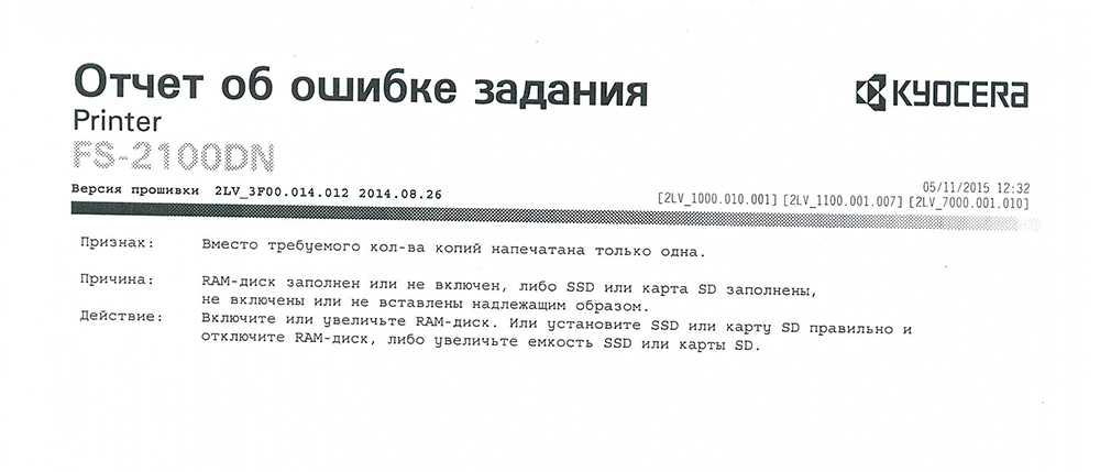
В итоге на самом собрании у меня не получилось быстро решить проблему, а вот после собрания пришлось повозиться и вот как эта бяка лечиться (но к сожалению такую операцию нужно проделывать на каждой станции)
- для начала зайдем в свойство принтера

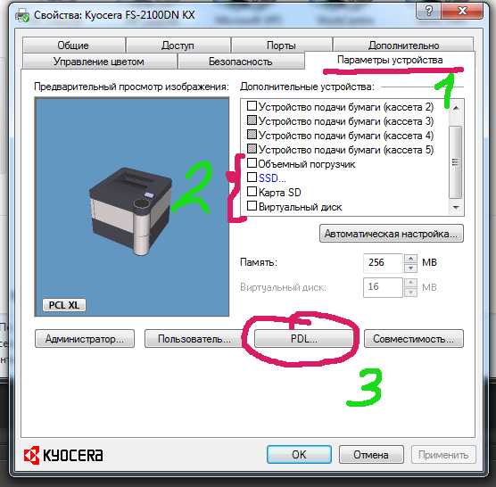

Вот и все. И после таких манипуляций принтер заработал. Очень конечно меня огорчил этот косяк на принтере Киосера, потому как обычная и стандартная задача для принтера вылилась в ковыряниях в драйверах и настройках. Очень надеюсь, что данную ситуацию исправят разработчики и также надеюсь, что в процессе эксплуатации таких курьезов не будет с аппаратом! Фирма то вроде серьезная, а подход не очень.
Источник
Как очистить память на принтере kyocera?
Как очистить память принтера Kyocera?
Чтобы очистить энергонезависимую память или буферизованные данные принтера, выключите принтер.
.
Очистка памяти принтера
- На начальном экране выберите Параметры > Устройство > Обслуживание > Очистка при простое.
- Поставьте флажок Очистить энергонезависимую память и коснитесь СТЕРЕТЬ.
- Следуйте указаниям на дисплее.
Как сбросить ошибку на принтере Kyocera?
Kyocera: сброс ошибки «установлен неоригинальный картридж с тонером»
- Сброс счетчика осуществляется одновременным нажатием кнопок «Старт» и «Стоп» (либо «Сброс» и «ОК») на принтере и удержанием их в течение нескольких секунд.
- На разных принтерах или мфу комбинация может отличаться.
Как сбросить принтера до заводских настройки Kyocera?
Kyocera m2540dn сброс до заводских настроек reset
- Включить МФУ Kyocera m2540dn.
- Войти в тех. меню, набрав 10871087.
- Набрать в техническом меню U021.
- Нажать на панели кнопку «Старт».
- Выбрать [EXECUTE] и нажать «Старт».
- Выключить питание.
Как зайти в системное меню Kyocera?
Для входа в инженерное меню необходимо после выхода аппарата в готовность набрать комбинацию цифр — 10871087. При этом все цифры необходимо вводить без пауз, не обращая внимания на «протесты» аппаратов. При удачном входе в инженерное меню на экране пользователь увидит символы U000.
Как сбросить пароль на принтере Kyocera?
Для сброса настроек по умолчанию (hard reset) необходимо включить МФУ и ввести комбинацию цифр 10871087. Затем необходимо перейти к другим подразделам меню и найти строку Set Factory Def. Совершаем переход и подтверждаем действие кнопкой «ОК».
Как очистить память принтера Кэнон?
СПРАВОЧНАЯ ИНФОРМАЦИЯ
- Убедитесь в том, что аппарат включен.
- Нажмите кнопку [FAX/ФАКС]. .
- Нажмите кнопку [Menu/Меню]. .
- С помощью кнопок выберите [Memory reference/Обращение к памяти] и нажмите кнопку OK. .
- С помощью кнопок выберите [Delete all docs/Удалить все документы] и нажмите кнопку OK.
Как перезагрузить Киосеру?
Первый метод:
- Нажмите и удерживайте кнопку питания в течение короткого времени, чтобы выключить мобильный телефон.
- На втором шаге нажмите и удерживайте несколько секунд клавишу уменьшения громкости + питания .
- Отпустите все кнопки, когда появится логотип KYOCERA .
Как перезагрузить принтер Ecosys fs-1020MFP?
Перезаправив картридж у KYOCERA FS—1020MFP, иногда можно столкнуться с проблемой — аппарат позволит напечатать несколько листов, а потом впадает в ошибку E-0001. Удерживаем эти кнопки 3-8 секунд, до появления бегущих по кругу индикаторов на дисплее, и отпускаем. Можно пользоваться!
Что делать если принтер Kyocera не печатает?
Первое, что нужно сделать – это выключить принтер из сети, подождать некоторое время и включить повторно. Второе, проверить наличие в лотке бумаги, нет ли замятия бумаги внутри принтера и не переполнен ли выходной лоток.
Источник
МобилЛэнд
Что значит ошибка c7990 на kyocera?
Она означает что переполнен бункер с отработанным тонером. Дело в том, что технология лазерной печати построена таким образом, что в процессе печати принтера неизбежно появляется “лишний” отработанный тонер. Он не подходит для повторного использования и поэтому складируется в отдельный бункер, который присутствует либо на самом печатающем картридже, либо стоит как отдельный элемент принтера.
Чтобы не допустить полное его заполнение и выход отработанного тонера наружу (а он является летучим и весьма вредным веществом, крайне не рекомендуемым для вдыхания) в большинстве лазерных принтеров реализована система слежения за его наполнением. И ошибка c7990 на принтерах kyocera как раз и есть тот самый сигнал, который говорит, что пора почистить бункер отработанного тонера.
Почему возникает
Суть лазерной печати заключается в нанесении тонера на поверхность фотовала, заряженного противоположенным током. Порошок накладывается на всю поверхность, но остается только на определенных участках. Весь лишний удаляется в специальную емкость, а оставшейся запекается на бумаге в печке.
В этом случае, нас интересует судьба только оставшегося в принтере тонера. Он автоматически помещается в бункер отходов. В дальнейшем не используется для печати. Легко догадаться, что эта емкость имеет свой ресурс. Когда он заканчивается, устройство должно предупредить пользователя, что следует предпринять определенные действия. Разные марки принтеров делают это по-своему, а Киосера выдает ошибку с7990.
Решение
Способы решения напрашиваются сами. Необходимо почистить отработанный тонер.
- Отключите принтер от электропитания. Вытяните шнур питания из розетки.
- Откройте переднюю крышку.
- Сейчас Вы увидите проявочный узел. Его вынимаем.
- Дальше идет фотобарабан, который вытягиваем за зеленные ручки, чтобы не повредить поверхность.
- Кладем его на стол, который предварительно нужно застелить старой газетой или бумагой.
- Осматриваем картридж и находим места, через которые извлекаются остатки тонера.
- Через эти отверстия нужно высыпать порошок.
Делайте это на улице или помещении, где нет сквозняка. Помните, что вещество очень вредно для человека и окружающей среды, так как изготовлено из нефти. Используйте резиновые перчатки, а если есть бытовой респиратор, его тоже можно применить, чтобы защититься от вредной пыли.
В целях профилактики дальнейшего возникновения ошибки c7990 на принтерах Kyocera следует проводить чистку отработки при каждой заправке новой порции порошка. Если пополнение не производите самостоятельно, то в сервисном центре это должны сделать, но напомнить не будет лишним.
Первый вариант сброса ошибки С7990
Этот вариант подойдет для некоторых моделей Kyocera. Делается это очень просто:
- Первое что требуется сделать это открытье переднюю крышку, как показано на рисунке:

Откройте переднюю крышку - Далее вытащите картридж с блоком проявки из МФУ. Можно отдельно, а можно и вместе.
Вытащите узел проявки из МФУ - Теперь извлеките узел фотобарабана из МФУ, удерживая за зеленые или синие рычаги обеими руками.
Извлеките узел барабана из МФУ


Инструкция: чистка бункера отработки на примере Kyocera P2235d / M2135dn / M2635dn / M2735dw
Для начала следует вынуть совместимый с МФУ Kyocera P2235d / M2135dn / M2635dn / M2735dw драм картридж DK-1150:
- откройте крышку с обратной стороны устройства;
- достаньте вал проявки;
- выньте драм-картридж.

Если у вас старая комплектация драм-картриджа DK-1150, тогда достаточно будет подковырнуть технологическое отверстие плоской отверткой и вытрясти отработку в герметичный пакет.

Новые драм-картриджи DK-1150 лишены технологического отверстия.
Проблему с чисткой можно решить полной разборкой детали (см. следующий раздел) или аккуратным сверлением бункера отработки. Получившееся отверстие затем стоит заклеить плотным скотчем, а уже при необходимости открывать.
Устранение ошибки C7990 – Шаг №1
Первое, что необходимо сделать, чтобы ошибка C7990 больше не беспокоила, это выключить печатающее устройство. Затем открыть переднюю крышку. Аккуратно, не торопясь, извлечь блок проявки. Извлекать нужно вместе с тонер-картриджем. Просто потяните его на себя, он выйдет.

Выключаем МФУ кнопкой включения/выключения питания. Открываем крышку и извлекаем блок проявки.
Шаг №2
После того как блок проявки извлечён, отложите его в сторону. Второе, что делаем, это извлекаем драм-юнит. Именно по его вине появилась на дисплее устройства ошибка C7990. Вытаскиваем драм также, как и блок проявки, потянув на себя. Тянуть нужно за специально предназначенные для этого зелёные вставки по бокам.

Извлекаем драм-юнит за специальные полукольца. Ошибка C7990 вызвана именно проблемами с драм-юнитом печатающего устройства Kyocera.
Шаг №3
Третье, на демонтированном драм-юните необходимо отщелкнуть небольшую крышку, закрывающую отверстие для чистки отсека отработки. Чтобы это сделать, поворачиваем драм зелёными вставками назад. По бокам находятся крышки. Отщелкнуть нужно одну из них, без разницы какую. Убрав закрывающую крышку высыпаем отработку.

При помощи плоской отвёртки отгибаем защёлки и снимаем крышку закрывающую бункер отработанного тонера.
После того как сняли крышку закрывающую бункер отработанного тонера в драме, высыпаем отработку через открывшуюся полость. Можно воспользоваться специальным пылесосом.
Шаг №4
Итак, отсек для отработанного тонера после проделанных манипуляций пуст. Причину вызвавшую ошибку C7990 на печатающем устройстве Kyocera устранили. Ставим крышечку на своё место. Вставляем драм-юнит, а затем блок проявки с тонер-картриджем в аппарат. Закрываем переднюю крышку устройства. Включаем МФУ и радуемся устранением проблемы.
Где находится бункер отработанного тонера?
Бункер расположен за блоком фотобарабана DK. Чтобы добраться до него необходимо вынуть блок проявки DV. Блок проявки — это блок, в который вставляется тонер-картридж.
При попытке использования картриджа – чип блокирует систему
Производители все время усложняют уровень защиты чипов в картриджах, теперь задача чипа заключается не в анализе оставшегося ресурса печати, а в блокировании возможности заправки картриджа.
Производителей можно разделить на две группы:
1. Производители, чья техника продолжает работу, когда счетчик отсчитал положенное количество копий, чип не блокирует работу заправленного картриджа.
К ним относятся: HP, Canon, Kyocera, Brother (у последнего применяются механические флажки).
В таких картриджах чип можно не менять, картридж продолжит работу и после заправки. В цветных картриджах чипы иногда требуется заменять, кроме счетчика они дополнительно хранят информацию о согласовании цветов.
2. Компании, которые устанавливают блокирующиеся чипы, которые препятствуют заправке картриджей.
К ним относятся: Lexmark, Samsung, Xerox, Pantum.
Чтобы картридж этих производителей продолжил свою работу после заправки, требуется обязательная установка нового чипа, даже полный картридж без чипа работать не будет. Либо, можно воспользоваться альтернативным путем – прошить принтер.
Прошивка принтера – это внесение изменений во внутреннее программное обеспечение самого аппарата так, чтобы принтер «забыл» о чипе и всегда думал, что картридж полный.
Какие еще есть причины возникновения ошибки с7990?
Причиной может послужить выход из строя датчика или платы управления. В этом случае лучше вызвать специалиста сервисного центра.
P.S. При переполненном бункера некоторые аппараты не всегда выдают ошибку С7990 на дисплее. Иногда пользователь об этом может узнать, когда принтер начинает трещать. Если вовремя не провести чистку, ломается шестерёнка. В этом случае, необходим уже ремонт или замена фотобарабана (бункера WT)
Дополнительная информация, касающаяся ошибки C7990
Если вы извлекли драм-юнит и на нём нет крышек закрывающих доступ для очистки отработки, то Вам нужно проделать отверстие самостоятельно. В некоторых моделях печатающих устройств Kyocera, отверстия на драм-юните для очистки отработки отсутствуют. После того как проделали отверстие и высыпали отработанный тонер обязательно заклейте отверстие скотчем! Далее установите драм и блок проявки на своё место, включите устройство. Ошибка C7990 больше Вас не побеспокоит, до следующего переполнения отработанным тонером.
Сброс сообщения «Замените МК» на МФУ kyocera 1035/2035/2535
Итак, делается это очень просто:
- Набираем на клавиатуре код: 10871087 и попадаем в сервисное меню
- Открываем программу u251
- Выбираете стрелочками «clear«
- Для выхода выполняете программу u001 (Не все модели поддерживают такой метод выхода из инженерного меню)
Если у Вас не получилось выйти из инженерного меню по программе u001, то просто выключите и включите Ваш аппарат.
Данным действием мы выполняем сброс счетчика обслуживания!
На этом все, надоедливая просьба исчезла. Мой совет — если МФУ начало просить заменить ему детали (по пробегу) и Вы еще ни разу в нем ничего не меняли, советую заранее прикупить новый Drum Unit DK-170 (проверьте, какой стоит у Вас!), так как это обычно первое, что выходит из строя и печать начинается с черными полосами.
Мы надеемся, что данная статья была полезна для Вас.
Расшифровка кода ошибки по индикаторам
Как расшифровать код ошибки по миганиям индикаторов?
Поле индикаторов в принтере Kyosera P2035D разделено на 8 секторов.

Информационных всего пять: пустые сектора, 1, 2, 3, 4.
Начало передачи кода – это мигание всех четырех секторов одновременно. Далее передается четырехзначный код последовательно. Каждое мигание – это цифра от 1 до 9 в двоичном формате.
Вес каждого сектора:
пустые сектора – 0
1 сектор – единица
2 сектор – двойка
3 сектор – четверка
4 сектор – восьмерка.
Например, код 7990 передается так. Мигают 1, 2, 3, 4 сектора одновременно (разделитель). Затем мигают 1, 2, 3 (1+2+4=7). После мигают 1, 4 (1+8=9). Потом повторяется 1, 4 (1+8=9). Завершает цикл миганием пустых секторов 0. Итого, 7990
Обновленные коды ошибок для популярной серии принтеров Kyocera
Коды ошибок для популярной серии принтеров Kyocera FS-2100DN, FS-4100DN, FS-4200DN, FS-4300DN, а также для пришедших им на смену ECOSYS P3045dn, ECOSYS P3050dn, ECOSYS P3055dn, ECOSYS P3060dn.
1.Self-diagnostic function — Функция самодиагностики
Принтеры оснащены функцией самодиагностики. Когда проблема обнаружена, устройство прекращает печать и на панели управления отображается сообщение об ошибке. Сообщение об ошибке состоит из четырехзначного кода, указывающего на тип ошибки.
| Code | Contents | Causes | Check procedures/ corrective measures |
| 0100 | Backup memory device error | Defective flash memory. | Replace the main PWB and check for correct operation (see page 1-5-22). |
| Defective main PWB. | |||
| 0120 | MAC address data error For data in which the MAC address is invalid. | Defective flash memory. | Replace the main PWB and check for correct operation (see page 1-5-22). |
| Defective main PWB. | Replace the main PWB and check for correct operation (see page 1-5-22). | ||
| 0130 | Backup memory read/write error (main PWB) | Defective flash memory. | Replace the main PWB and check for correct operation (see page 1-5-22). |
| Defective main PWB. | |||
| 0140 | Backup memory data error (main PWB) | Defective flash memory. | Replace the main PWB and check for correct operation (see page 1-5-22). |
| Defective main PWB. | |||
| 0150 | Backup memory read/write error (engine PWB) Detecting engine PWB EEPROM communication error. | Improper installation engine PWB EEPROM. | Check the installation of the EEPROM and remedy if necessary. |
| Defective engine PWB. | Replace the engine PWB and check for correct operation (see page 1-5-22). | ||
| Device damage of EEPROM. | Contact the Service Administrative Division. | ||
| 0160 | Backup memory data error (engine PWB) | Defective EEPROM. | Replace the engine PWB and check for correct operation (see page 1-5-22). |
| Defective engine PWB. | |||
| 0170 | Billing counting error A checksum error is detected in the main and engine backup memories for the billing counters. | Data damage of EEPROM. | Contact the Service Administrative Division. |
| Defective PWB. | Replace the main PWB or the engine PWB and check for correct operation (see page 15-22, 1-5-22). | ||
| 0190 | Backup memory device error (engine PWB) | Defective engine PWB. | Replace the engine PWB and check for correct operation (see page 1-5-22). |
| 0800 | Image processing error JAM010x is detected twice. | Defective connector cable or poor contact in the connector. | Reinsert the connector. Also check for continuity within the connector cable. If none, replace the cable. Fuser thermistor 1/2 and fuser thermistor connect PWB(YC1/2) Fuser thermistor connect PWB(YC3) and engine PWB (YC21) |
| Defective fuser thermistor. | Replace the fuser thermistor connect PWB . | ||
| Replace the fuser unit (see page 1-5-19). | |||
| Defective engine PWB. | Replace the engine PWB and check for correct operation (see page 1-5-22). | ||
| Defective main PWB. | Replace the main PWB and check for correct operations page 1-5-22). | ||
| 0840 | Faults of RTC Unable to communicate with the RTC device normally. The RTC data is mismatched due to dead battery or short-circuit with the metal part. | Other RTC device failure due to dead battery or short-circuit with the metal part. | Restart the main unit and set the correct time from the operation panel. Repair it if the battery comes off from the main PWB. |
| Defective main PWB. | Replace the main PWB and check for correct operation (see page 1-5-22). | ||
| 1010 | Lift motor error (60/55/50 ppm model only) After cassette 1 is inserted, lift sensor does not turn on within 10 s. This error is detected five times successively. | Defective bottom plate elevation mechanism in the cassette. | Check to see if the bottom plate can move smoothly and repair it if any problem is found. |
| Defective connector cable or poor contact in the connector. | Reinsert the connector. Also check for continuity within the connector cable. If none, replace the cable. Lift motor and engine PWB (YC13) | ||
| Defective drive transmission system of the lift motor. | Check if the gears rotate smoothly. If not, grease the bushes and gears. Check for broken gears and replace if any. | ||
| Defective lift motor. | Replace the lift motor. | ||
| Defective engine PWB. | Replace the engine PWB and check for correct operation (see page 1-5-22). | ||
| 1020 | PF lift motor 1 error (paper feeder) After cassette 2 is inserted, PF lift sensor 1 does not turn on. This error is detected four times successively. | Defective bottom plate elevation mechanism in the cassette. | Check to see if the bottom plate can move smoothly and repair it if any problem is found. |
| Defective connector cable or poor contact in the connector. | Reinsert the connector. Also check for continuity within the connector cable. If none, replace the cable. PF lift motor 1 and PF main PWB (YC7) | ||
| Defective drive transmission system of the PF lift motor. | Check if the gears rotate smoothly. If not, grease the bushes and gears. Check for broken gears and replace if any. | ||
| Defective PF lift motor. | Replace the PF lift motor 1. | ||
| Defective PF main PWB. | Replace the PF main PWB (Refer to the service manual for the paper feeder). | ||
| 1030 | PF lift motor 2 error (paper feeder) After cassette 3 is inserted, PF lift sensor 2 does not turn on. This error is detected four times successively. | Defective bottom plate elevation mechanism in the cassette. | Check to see if the bottom plate can move smoothly and repair it if any problem is found. |
| Defective connector cable or poor contact in the connector. | Reinsert the connector. Also check for continuity within the connector cable. If none, replace the cable. PF lift motor 2 and PF main PWB (YC7) | ||
| Defective drive transmission system of the PF lift motor. | Check if the gears rotate smoothly. If not, grease the bushes and gears. Check for broken gears and replace if any. | ||
| Defective PF lift motor. | Replace the PF lift motor 2. | ||
| Defective PF main PWB. | Replace the PF main PWB (Refer to the service manual for the paper feeder). | ||
| 1040 | PF lift motor 3 error (paper feeder) After cassette 4 is inserted, PF lift sensor 3 does not turn on. This error is detected four times successively. | Defective bottom plate elevation mechanism in the cassette. | Check to see if the bottom plate can move smoothly and repair it if any problem is found. |
| Defective connector cable or poor contact in the connector. | Reinsert the connector. Also check for continuity within the connector cable. If none, replace the cable. PF lift motor 3 and PF main PWB (YC7) | ||
| Defective drive transmission system of the PF lift motor. | Check if the gears rotate smoothly. If not, grease the bushes and gears. Check for broken gears and replace if any. | ||
| Defective PF lift motor. | Replace the PF lift motor 3. | ||
| Defective PF main PWB. | Replace the PF main PWB (Refer to the service manual for the paper feeder). | ||
| 1050 | PF lift motor 4 error (paper feeder) After cassette 5 is inserted, PF lift sensor 4 does not turn on. This error is detected four times successively. | Defective bottom plate elevation mechanism in the cassette. | Check to see if the bottom plate can move smoothly and repair it if any problem is found. |
| Defective connector cable or poor contact in the connector. | Reinsert the connector. Also check for continuity within the connector cable. If none, replace the cable. PF lift motor 4 and PF main PWB (YC7) | ||
| Defective drive transmission system of the PF lift motor. | Check if the gears rotate smoothly. If not, grease the bushes and gears. Check for broken gears and replace if any. | ||
| Defective PF lift motor. | Replace the PF lift motor 4. | ||
| Defective PF main PWB. | Replace the PF main PWB (Refer to the service manual for the paper feeder). | ||
| 1140 | BPF lift motor upward error (Bulk paper feeder) BPF lift maximum sensor does not turn on. The lock signal of the motor is detected continuously three times. | Defective connector cable or poor contact in the connector. | Reinsert the connector. Also check for continuity within the connector cable. If none, replace the cable. BPF lift motor and BPF main PWB (YC4) |
| Defective drive transmission system of the motor. | Check if the gears rotate smoothly. If not, grease the bushes and gears. Check for broken gears and replace if any. | ||
| Defective BPF lift motor. | Replace the BPF lift motor. | ||
| Defective BPF main PWB. | Replace the BPF main PWB (Refer to the service manual for the paper feeder). | ||
| 1150 | BPF lift motor downward error (Bulk paper feeder) BPF lift minimum sensor does not turn on. The lock signal of the motor is detected continuously three times. When detecting an overcurrent detection signal. | Defective connector cable or poor contact in the connector. | Reinsert the connector. Also check for continuity within the connector cable. If none, replace the cable. BPF lift motor and BPF main PWB (YC4) |
| Defective drive transmission system of the motor. | Check if the gears rotate smoothly. If not, grease the bushes and gears. Check for broken gears and replace if any. | ||
| Defective BPF lift motor. | Replace the BPF lift motor. | ||
| Defective BPF main PWB. | Replace the BPF main PWB (Refer to the service manual for the paper feeder). | ||
| 1800 | Paper feeder 1 communication error A communication error is detected 10 times in succession. | Improper installation paper feeder. | Follow installation instruction carefully again. |
| Defective connector cable or poor contact in the connector. | Reinsert the connector. Also check for continuity within the connector cable. If none, replace the cable. PF main PWB (YC3) and engine PWB (YC22) | ||
| Defective engine PWB. | Replace the engine PWB and check for correct operation (see page 1-5-22). | ||
| Defective PF main PWB. | Replace the PF main PWB (Refer to the service manual for the paper feeder). | ||
| 1810 | Paper feeder 2 communication error A communication error is detected 10 times in succession. | Improper installation paper feeder. | Follow installation instruction carefully again. |
| Defective connector cable or poor contact in the connector. | Reinsert the connector. Also check for continuity within the connector cable. If none, replace the cable. PF main PWB (YC3) and engine PWB (YC22) | ||
| Defective PF main PWB. | Replace the PF main PWB (Refer to the service manual for the paper feeder). | ||
| 1820 | Paper feeder 3 communication error A communication error is detected 10 times in succession. | Improper installation paper feeder. | Follow installation instruction carefully again. |
| Defective connector cable or poor contact in the connector. | Reinsert the connector. Also check for continuity within the connector cable. If none, replace the cable. PF main PWB (YC3) and engine PWB (YC22) | ||
| Defective PF main PWB. | Replace the PF main PWB (Refer to the service manual for the paper feeder). | ||
| 1830 | Paper feeder 4 communication error A communication error is detected 10 times in succession. | Improper installation paper feeder. | Follow installation instruction carefully again. |
| Defective connector cable or poor contact in the connector. | Reinsert the connector. Also check for continuity within the connector cable. If none, replace the cable. PF main PWB (YC3) and engine PWB (YC22) | ||
| Defective PF main PWB. | Replace the PF main PWB (Refer to the service manual for the paper feeder). | ||
| 1900 | Paper feeder 1/BPF paper feeder EEPROM error When writing the data, the write data and the read data is not in agreement. | Defective PF main PWB. | Replace the PF main PWB or the BPF main PWB (Refer to the service manual for the paper feeder). |
| Device damage of EEPROM. | |||
| 1910 | Paper feeder 2 EEPROM error When writing the data, the write data and the read data is not in agreement. | Defective PF main PWB. | Replace the PF main PWB (Refer to the service manual for the paper feeder). |
| Device damage of EEPROM. | |||
| 1920 | Paper feeder 3 EEPROM error When writing the data, the write data and the read data is not in agreement. | Defective PF main PWB. | Replace the PF main PWB (Refer to the service manual for the paper feeder). |
| Device damage of EEPROM. | |||
| 1930 | Paper feeder 4 EEPROM error When writing the data, the write data and the read data is not in agreement. | Defective PF main PWB. | Replace the PF main PWB (Refer to the service manual for the paper feeder). |
| Device damage of EEPROM. | |||
| 2000 | Main motor drive error The main motor is not stabilized within 2 s after driving starts. | Defective connector cable or poor contact in the connector. | Reinsert the connector. Also check for continuity within the connector cable. If none, replace the cable. Main motor and engine PWB (YC4) |
| Defective drive transmission system of the main motor. | Check if the rollers and gears rotate smoothly. If not, grease the bushes and gears. Check for broken gears and replace if any. | ||
| Defective main motor. | Replace the main motor. | ||
| Defective engine PWB. | Replace the engine PWB and check for correct operation (see page 1-5-22). | ||
| 2010 | Main motor steady-state error Stable OFF is detected for 2 s continuously after main motor stabilized. | Defective connector cable or poor contact in the connector. | Reinsert the connector. Also check for continuity within the connector cable. If none, replace the cable. Main motor and engine PWB (YC4) |
| Defective drive transmission system of the main motor. | Check if the rollers and gears rotate smoothly. If not, grease the bushes and gears. Check for broken gears and replace if any. | ||
| Defective main motor. | Replace the main motor. | ||
| Defective engine PWB. | Replace the engine PWB and check for correct operation (see page 1-5-22). | ||
| 2200 | Drum motor drive error (60/55/50 ppm model only) The drum motor is not stabilized within 2 s after driving starts. | Defective connector cable or poor contact in the connector. | Reinsert the connector. Also check for continuity within the connector cable. If none, replace the cable. Drum motor and engine PWB (YC4) |
| Defective drive transmission system of the drum motor. | Check if the rollers and gears rotate smoothly. If not, grease the bushes and gears. Check for broken gears and replace if any. | ||
| Defective drum motor. | Replace the drum motor. | ||
| Defective engine PWB. | Replace the engine PWB and check for correct operation (see page 1-5-22). | ||
| 2210 | Drum motor steady-state error (60/55/50 ppm model only) Stable OFF is detected for 2 s continuously after drum motor stabilized. | Defective connector cable or poor contact in the connector. | Reinsert the connector. Also check for continuity within the connector cable. If none, replace the cable. Drum motor and engine PWB (YC4) |
| Defective drive transmission system of the drum motor. | Check if the rollers and gears rotate smoothly. If not, grease the bushes and gears. Check for broken gears and replace if any. | ||
| Defective drum motor. | Replace the drum motor. | ||
| Defective engine PWB. | Replace the engine PWB and check for correct operation (see page 1-5-22). | ||
| 2330 | Fuser pressure release motor error (Over-current) The over-current detection signal of the motor is detected continuously twenty times. | Defective connector cable or poor contact in the connector. | Reinsert the connector. Also check for continuity within the connector cable. If none, replace the cable. Fuser pressure release motor and relay-L PWB(YC11) Relay-L PWB(YC3) and engine PWB(YC2) |
| Defective drive transmission system of the fuser pressure release motor. | Check if the gears rotate smoothly. If not, grease the bushes and gears. Check for broken gears and replace if any. | ||
| Defective fuser pressure release motor. | Replace the fuser pressure release motor. | ||
| Defective PWB. | Replace the relay-L PWB or engine PWB. (See Page 1-5-24,1-5-22) | ||
| 2340 | Fuser pressure release motor error (Timeout) The position detection sensor is not detected continuously for 30 s. | Defective connector cable or poor contact in the connector. | Reinsert the connector. Also check for continuity within the connector cable. If none, replace the cable. Fuser pressure release motor and relay-L PWB(YC11) Relay-L PWB(YC1) and engine PWB(YC2) |
| Defective drive transmission system of the fuser pressure release motor. | Check if the gears rotate smoothly. If not, grease the bushes and gears. Check for broken gears and replace if any. | ||
| Defective fuser pressure release motor. | Replace the fuser pressure release motor. | ||
| Defective PWB. | Replace the relay-L PWB or engine PWB. (See Page 1-5-24,1-5-22) | ||
| 2600 | PF drive motor 1 error (paper feeder 1) When the PF drive motor is driven, error signal is detected continuously for 2 s. | Defective connector cable or poor contact in the connector. | Reinsert the connector. Also check for continuity within the connector cable. If none, replace the cable. PF drive motor 1 and PF main PWB (YC6) |
| Defective drive transmission system of the PF drive motor. | Check if the rollers and gears rotate smoothly. If not, grease the bushes and gears. Check for broken gears and replace if any. | ||
| Defective PF drive motor. | Replace the PF drive motor 1. | ||
| Defective PF main PWB. | Replace the PF main PWB (Refer to the service manual for the paper feeder). | ||
| 2610 | PF drive motor 2 error (paper feeder 2) When the PF drive motor is driven, error signal is detected continuously for 2 s. | Defective connector cable or poor contact in the connector. | Reinsert the connector. Also check for continuity within the connector cable. If none, replace the cable. PF drive motor 2 and PF main PWB (YC6) |
| Defective drive transmission system of the PF drive motor. | Check if the rollers and gears rotate smoothly. If not, grease the bushes and gears. Check for broken gears and replace if any. | ||
| Defective PF drive motor. | Replace the PF drive motor 2. | ||
| Defective PF main PWB. | Replace the PF main PWB (Refer to the service manual for the paper feeder). | ||
| 2620 | PF drive motor 3 error (paper feeder 3) When the PF drive motor is driven, error signal is detected continuously for 2 s. | Defective connector cable or poor contact in the connector. | Reinsert the connector. Also check for continuity within the connector cable. If none, replace the cable. PF drive motor 3 and PF main PWB (YC6) |
| Defective drive transmission system of the PF drive motor. | Check if the rollers and gears rotate smoothly. If not, grease the bushes and gears. Check for broken gears and replace if any. | ||
| Defective PF drive motor. | Replace the PF drive motor 3. | ||
| Defective PF main PWB. | Replace the PF main PWB (Refer to the service manual for the paper feeder). | ||
| 2630 | PF drive motor 4 error (paper feeder 4) When the PF drive motor is driven, error signal is detected continuously for 2 s. | Defective connector cable or poor contact in the connector. | Reinsert the connector. Also check for continuity within the connector cable. If none, replace the cable. PF drive motor 4 and PF main PWB (YC6) |
| Defective drive transmission system of the PF drive motor. | Check if the rollers and gears rotate smoothly. If not, grease the bushes and gears. Check for broken gears and replace if any. | ||
| Defective PF drive motor. | Replace the PF drive motor 4. | ||
| Defective PF main PWB. | Replace the PF main PWB (Refer to the service manual for the paper feeder). | ||
| 4000 | Polygon motor synchronization error The polygon motor is not stabilized within 20 s after driving starts. | Defective connector cable or poor contact in the connector. | Reinsert the connector. Also check for continuity within the connector cable. If none, replace the cable. Polygon motor and engine PWB (YC15) |
| Defective polygon motor. | Replace the laser scanner unit (see page 15-18). | ||
| Defective engine PWB. | Replace the engine PWB and check for correct operation (see page 1-5-22). | ||
| 4201 | BD steady-state error When the value of Register BDSET is 1 after setting Register BDSET as one and pass- | Defective connector cable or poor contact in the connector. | Reinsert the connector. Also check for continuity within the connector cable. If none, replace the cable. APC PWB(YC1) and engine PWB (YC16) APC PWB(YC2) and PD PWB(YC1) |
| ing by BD1 cycle. | Defective PD PWB. | Replace the laser scanner unit (see page 15-18). | |
| Defective engine PWB. | Replace the engine PWB and check for correct operation (see page 1-5-22). | ||
| 5100 | Chager current error When the current value measured at the time of potential adjustment is less than 20 ^A. | Defective connector cable or poor contact in the connector. | Reinsert the connector. Also check for continuity within the connector cable. If none, replace the cable. Chager unit and high voltage PWB High voltage PWB (YC101) and engine PWB (YC19) |
| Defective high voltage PWB. | Replace the high voltage PWB and check for correct operation (see page 1-5-26). | ||
| Defective engine PWB. | Replace the engine PWB and check for correct operation (see page 1-5-22). | ||
| 6000 | Broken fuser heater wire The detection temperature of fuser thermistor 2 is 100 °C/ 212°F or less after the fuser heater lamp has been turned on continuously for 30 s. | Defective connector cable or poor contact in the connector. | Reinsert the connector. Also check for continuity within the connector cable. If none, replace the cable. Fuser heater and power source PWB (YC2) Fuser thermistor and Fuser thermistor connect PWB(YC1 and YC2) Fuser thermistor connect PWB(YC3) and engine PWB (YC21) |
| Deformed connector pin. | See page 1-4-19. | ||
| Defective triac. | See page 1-4-19. | ||
| Fuser thermostat triggered. | Reinsert the fuser unit (see page 1-5-19). | ||
| Broken fuser heater wire. | |||
| Defective engine PWB. | Replace the engine PWB and check for correct operation (see page 1-5-22). | ||
| 6020 | Abnormally high fuser thermistor 2 temperature | Deformed connector pin. | See page 1-4-19. |
| The detection temperature of fuser thermistor 2 is higher than 235°C/455°F. | Defective triac. | See page 1-4-19. | |
| Shorted fuser thermistor. | Replace the fuser unit (see page 1-5-19). | ||
| In a heater-off state, the detection temperature of fuser thermistor 2 is higher than 195°C/383°F after the detection temperature of fuser thermistor 2 was 155°C/311 °F or less. | Defective engine PWB. | Replace the engine PWB and check for correct operation (see page 1-5-22). | |
| 6030 | Broken fuser thermistor 2 wire A/D value of the fuser thermistor 2 exceeds 1019 bit continuously for 4 s during warming up. | Defective connector cable or poor contact in the connector. | Reinsert the connector. Also check for continuity within the connector cable. If none, replace the cable. Fuser thermistor and fuser thermistor connect PWB(YC2) Fuser thermistor connect PWB(YC3) and engine PWB (YC21) |
| Deformed connector pin. | See page 1-4-19. | ||
| Defective triac. | See page 1-4-19. | ||
| Defective fuser thermistor. | Replace the fuser unit (see page 1-5-19). | ||
| Defective engine PWB. | Replace the engine PWB and check for correct operation (see page 1-5-22). | ||
| 6000/ | Broken fuser heater wire | Deformed connec- | If the I/F connector pins of the fuser unit and |
| 6020/ | Abnormally high fuser | tor pin. | the main unit are deformed owing to foreign |
| thermistor 2 temperature | matters, replace the connectors or the units | ||
| 6030/ | Broken fuser thermistor 2 | including the connectors. | |
| 6120/ 6130/ Com- bined | wire Abnormally high fuser thermistor 1 temperature Broken fuser thermistor 1 wire | Defective triac. | Remove the power cord and check that the resistance between terminals T1 and T2 of the triac TRA31 and triac TRA41 are of several Mega-Ohms and not shorted (see figure 1-4-3). If failed, replace the power source PWB (see page 1-5-25). |
| 6120 | Abnormally high fuser thermistor 1 temperature | Deformed connector pin. | See page 1-4-19. |
| The detection temperature of fuser thermistor 1 is higher than 245°C/473°F. | Defective triac. | See page 1-4-19. | |
| Shorted fuser thermistor. | Replace the fuser unit (see page 1-5-19). | ||
| In a heater-off state, the detection temperature of fuser thermistor 1 is higher than 195°C/383°F after the detection temperature of fuser thermistor 1 was 155°C/311 °F or less. | Defective engine PWB. | Replace the engine PWB and check for correct operation (see page 1-5-22). | |
| 6130 | Broken fuser thermistor 1 wire A/D value of the fuser thermistor 1 exceeds 1019 bit continuously for 4 s during warming up. | Defective connector cable or poor contact in the connector. | Reinsert the connector. Also check for continuity within the connector cable. If none, replace the cable. Fuser thermistor and fuser thermistor connect PWB(YC1) Fuser thermistor connect PWB(YC3) and engine PWB (YC21) |
| Deformed connector pin. | See page 1-4-19. | ||
| Defective triac. | See page 1-4-19. | ||
| Defective fuser thermistor. | Replace the fuser unit (see page 1-5-19). | ||
| Defective engine PWB. | Replace the engine PWB and check for correct operation (see page 1-5-22). | ||
| 6400 | Zero-cross signal error While fuser heater control is performed, the zero-cross signal is not input within 2 s. | Defective connector cable or poor contact in the connector. | Reinsert the connector. Also check for continuity within the connector cable. If none, replace the cable. Power source PWB (YC3) and engine PWB (YC1) |
| Defective power source PWB or engine PWB. | Replace the power source PWB or the engine PWB and check for correct operation (see page 1-5-22). | ||
| 7100 | Toner sensor error Sensor output value of 930 or more continuously for 5 s. | Defective connector cable or poor contact in the connector. | Reinsert the connector. Also check for continuity within the connector cable. If none, replace the cable. Toner sensor and drum PWB (YC3) Drum connect PWB(YC2) and relay-L PWB (YC3) Relay-L PWB(YC1) and engine PWB (YC2) |
| Defective toner sensor. | Replace the developer unit. (See Page 1-5-13) | ||
| Defective engine PWB. | Replace the engine PWB and check for correct operation (see page 1-5-22). | ||
| 7400 | Developer unit non-installing error Sensor output value of 31 or less continuously for 5 s. | Defective connector cable or poor contact in the connector. | Reinsert the connector. Also check for continuity within the connector cable. If none, replace the cable. Toner sensor and drum PWB (YC3) Drum connect PWB(YC2) and relay-L PWB (YC3) Relay-L PWB(YC1) and engine PWB (YC2) |
| Defective toner sensor. | Replace the developer unit. (See Page 1-5-13) | ||
| Defective engine PWB. | Replace the engine PWB and check for correct operation (see page 1-5-22). | ||
| 7410 | Drum unit type mismatch error The drum PWB EEPROM does not communicate normally. Absence of the drum unit | Defective connector cable or poor contact in the connector. | Reinsert the connector. Also check for continuity within the connector cable. If none, replace the cable. Drum unit and drum connect PWB (YC1) Drum connect PWB(YC2) and relay-L PWB (YC3) Relay-L PWB(YC1) and engine PWB (YC2) |
| is detected. | Defective toner sensor. | Replace the drum unit. (See Page 1-5-13) | |
| Defective engine PWB. | Replace the engine PWB and check for correct operation (see page 1-5-22). | ||
| 7800 | Broken external thermistor wire The average of thermistor output value of 93 or less. | Defective connector cable or poor contact in the connector. | Reinsert the connector. Also check for continuity within the connector cable. If none, replace the cable. Operation PWB (YC1) and engine PWB (YC17) |
| Defective temperature sensor. | Replace the operation PWB. | ||
| 7810 | Short-circuited external thermistor wire The average of thermistor output value of 930 or more. | Defective connector cable or poor contact in the connector. | Reinsert the connector. Also check for continuity within the connector cable. If none, replace the cable. Operation PWB (YC1) and engine PWB (YC17) |
| Defective temperature sensor. | Replace the operation PWB. | ||
| 7900 | Drum unit EEPROM error No response is issued from the device in reading/writing for 5 ms or more and this problem is repeated five times successively. | Defective connector cable or poor contact in the connector. | Reinsert the connector. Also check for continuity within the connector cable. If none, replace the cable. Drum unit and drum connect PWB (YC1) Drum connect PWB(YC2) and relay-L PWB (YC3) Relay-L PWB(YC1) and engine PWB (YC2) |
| Mismatch of reading data from two locations occurs eight times successively. Mismatch between writing data and reading data occurs eight times successively. | Defective drum unit. | Replace the drum unit (see 1-5-15). | |
| F000 | Main PWB — operation PWB communication error | Defective connector cable or poor contact in the connector. | Reinsert the connector. Also check for continuity within the connector cable. If none, replace the cable. Operation PWB(YC1) and engine PWB (YC17) |
| Defective main PWB. | Turn the main power switch off/on to restart the machine. If the error is not resolved, replace main PWB (see page 1-5-22). | ||
| Defective operation PWB. | Replace the operation PWB and check for correct operation. | ||
| F010 | Main PWB checksum error | Defective main PWB. | Turn the main power switch off/on to restart the machine. If the error is not resolved, replace main PWB (see page 1-5-22). |
| F020 | Main PWB RAM checksum error | Defective main memory (RAM) in main PWB | Turn the main power switch off/on to restart the machine. If the error is not resolved, replace main PWB (see page 1-5-22). |
| Defective expended memory (DIMM) | Replace the expansion memory (DIMM). (See Page 1-2-12) Also in the case of the capacity besides specification, it displays. | ||
| F040 | Main PWB — print engine communication error | Defective main PWB. | Turn the main power switch off/on to restart the machine. If the error is not resolved, replace main PWB (see page 1-5-22). |
| Defective engine PWB. | Replace the engine PWB and check for correct operation (see page 1-5-22). | ||
| F050 | Print engine ROM checksum error | Defective engine PWB. | Turn the main power switch off/on to restart the machine. If the error is not resolved, replace engine PWB (see page 1-5-22). |
2. System Error (Fxxxx) Outline — Системная ошибка (Fxxxx)
| It locks on a Welcome screen.It locks on a starting logo (Taskalfa/Ecosys) screen.(Even if time passes for a definite period of time in more than * notes, a screen does not change) | (1) Check the harness, and the connection state of a connector between Panel Main boards, and perform an operation check. (2) Check contact of a DDR memory (extracting) and perform an operation check. If exchangeable, it will exchange and will perform an operation check. (3) U021 Controller backup initialization is carried out and an operation check is performed. (4) Exchange a PanelMain board and perform an operation check. (5) Exchange a Main board and perform an operation check. (6) It will get, if USBLOG is obtainable, and contact service headquarters. | 1. Panel Main IF (Engine PWB Relay) Main PWB: YC2 Engine PWB: YC20,YC30 Panel PWB: YC1 2. DDR memory Main PWB: YS1 | * note: 60[s] | |
| F000 | CF000 will be displayed if * notes progress is carried out for a definite period of time with a Welcome screen.The communication fault between Panel-Main boardsCommunication fault between Panel Core-Main Core Notes 2 | (1) Check the harness, and the connection state of a connector between Panel Main boards, and perform an operation check. (2) Check contact of a DDR memory (extracting) and perform an operation check. If exchangeable, it will exchange and will perform an operation check. (3) U021 Controller backup initialization is carried out and an operation check is performed. (4) Exchange a Main board and perform an operation check. (5) Exchange a PanelMain board and perform an operation check. (6) It will get, if USBLOG is obtainable, and contact service headquarters. | 1. Panel Main IF (Engine PWB Relay) Main PWB: YC2 Engine PWB: YC20,YC30 Panel PWB: YC1 2. DDR memory Main PWB: YS1 | * note: 60[s] |
| F15X | Abnormality detecting in an authentication device control section | (1) Check the harness between authentication device Main boards, and the connection situation of a connector, and perform an operation check. (2) Carry out U021 Main backup initialization and perform an operation check. (3) Exchange a Main board and perform an operation check. (4) Get USBLOG and contact service headquarters. | ^Authentication device Main IF Main PWB: YC6 Authentication device: IC card reader etc. | [Main body authentication device] USB-HOST connector [Main boad USB connector] Main boad: YC510 |
| F17X | Abnormality detecting in a printer data control part | (1) U021 Controller backup initialization is carried out and an operation check is performed. (2) Exchange a Main board and perform an operation check. (3) Get USBLOG and contact service headquarters. | ||
| F18X | Abnormality detecting in a Video control section | (1) Check the harness between Engine Main boards, and the connection state of a connector, and perform an operation check. (2) U021 Controller backup initialization is carried out and an operation check is performed. (3) Exchange an Engine board and perform an operation check. (4) Exchange a Main board and perform an operation check. (5) Get USBLOG and contact service headquarters. | ||
| F1DX | Abnormality detecting of the image memory Management Department | (1) U021 Controller backup initialization is carried out and an operation check is performed. (2) Exchange a Main board and perform an operation check. (3) Get USBLOG and contact service headquarters. | * Poor arrangement of F1 D4:Random Access Memory(1) Confirmation of U340(2) Initialization of a set point (U021) | |
| F21X | Abnormality detecting in an image-processing part | (1) Check contact of a DDR memory and perform an operation check. (2) Carry out U021 Main backup initialization and perform an operation check. (3) Exchange a Main board and perform an operation check. (4) Get USBLOG and contact service headquarters. | ||
| F22X | ||||
| F23X | ||||
| F24X | Abnormality detecting in the system Management Department | (1) Check contact of a DDR memory and perform an operation check. (2) Carry out U021 Main backup initialization and perform an operation check. (3) Exchange a Main board and perform an operation check. (4) Get USBLOG and contact service headquarters. | * F248 is the abnormalities of a printer process.In recurring by specific printer data, please give me cooperation at acquisition of capture data and USBLOG. | [Controller failure] Turn power on and off to clear. USB log is required for investigation. [Main PWB] There is no hard components that can be checked in the field. |
| F25X | Abnormality detecting in a network management department | (1) U021 Controller backup initialization is carried out and an operation check is performed. (2) Exchange a Main board and perform an operation check. (3) Get USBLOG and contact service headquarters. | * It may occur according to a visitor’s network environment. | [Main body External network] Ethernet network |
| F26X | Abnormality detecting in the system Management Department | (1) U021 Controller backup initialization is carried out and an operation check is performed. (2) Exchange a Main board and perform an operation check. (3) Get USBLOG and contact service headquarters. | ||
| F27X | ||||
| F28X | ||||
| F29X | ||||
| F2AX | ||||
| F2BX | Abnormality detecting in a network control part | (1) Carry out U021 Main backup initialization and perform an operation check. (2) Exchange a Main board and perform an operation check. (3) Get USBLOG and contact service headquarters. (Depending on an analysis result, it is packet capture acquisition) | [Main body External network] Ethernet network | |
| F2CX | ||||
| F2DX | ||||
| F2EX | ||||
| F2FX | ||||
| F30X | ||||
| F31X | ||||
| F32X | ||||
| F35X | Abnormality detecting in the printing controlling Management Department | (1) U021 Controller backup initialization is carried out and an operation check is performed. (2) Exchange a Main board and perform an operation check. (3) Get USBLOG and contact service headquarters. | ||
| F38X | Abnormality detecting in the authentication authorized Management Department | (1) U021 Controller backup initialization is carried out and an operation check is performed. (2) Exchange a Main board and perform an operation check. (3) Get USBLOG and contact service headquarters. | [Main body authentication device] USB-HOST connector [Main boad USB connector] Main boad: YC510 | |
| F3AX | Abnormality detecting in the Entity Management Department | (1) U021 Controller backup initialization is carried out and an operation check is performed. (2) Exchange a Main board and perform an operation check. (3) Get USBLOG and contact service headquarters. | ||
| F3BX | ||||
| F3CX | ||||
| F3DX | ||||
| F3EX | ||||
| F3FX | ||||
| F40X | ||||
| F41X | ||||
| F43X | ||||
| F44X | ||||
| F45X | ||||
| F46X | Abnormality detecting of a printer rendering part | (1) Exchange boards and perform an operation check. (2) the acquisition wish of USBLOG — carry out (Depending on the (2) case, it is print capture data acquisition) | * F46F is the abnormalities of a printer process.In recurring by specific printer data, please give me cooperation at acquisition of capture data and USBLOG. | |
| F4DX F4EX | Abnormality detecting in the Entity Management Department | (1) U021 Controller backup initialization is carried out and an operation check is performed. (2) Exchange a Main board and perform an operation check. (3) Get USBLOG and contact service headquarters. | [Main PWB] There is no hard components that can be checked in the field. | |
| F4FX | Abnormality detecting in the JOB Management Department | (1) U021 Controller backup initialization is carried out and an operation check is performed. (2) Exchange a Main board and perform an operation check. (3) Get USBLOG and contact service headquarters. | Since the USB log immediately after occurrence is needed for analysis, please give me cooperation of acquisition. | |
| F52X F53X F55X F56X F57X | Abnormality detecting in a JOB execution part | «(1) U021 Controller backup initialization is carried out and an operation check is performed. (2) Exchange a Main board and perform an operation check. (3) Get USBLOG and contact service headquarters. | Since the USB log immediately after occurrence is needed for analysis, please give me cooperation of acquisition. | |
| F61X | Abnormality detecting in a report creation part | (1) U021 Controller backup initialization is carried out and an operation check is performed. (2) Exchange a Main board and perform an operation check. (3) Get USBLOG and contact service headquarters. | Since the USB log immediately after occurrence is needed for analysis, please give me cooperation of acquisition. | [Controller failure] Turn power on and off to clear. USB log is required for investigation. |
| F63X | Abnormality detecting in a device control section | (1) U021 Controller backup initialization is carried out and an operation check is performed. (2) Exchange a Main board and perform an operation check. (3) Get USBLOG and contact service headquarters. | ||
| F68X | Abnormality detecting in a storage device control section | (1) U021 Controller backup initialization is carried out and an operation check is performed. (2) Exchange a Main board and perform an operation check. (3) Get USBLOG and contact service headquarters. | * F684 is the overwrite error at the time of an HDD security kit. | |
| F90X | Abnormality detecting in the extension application service part | (1) U021 Controller backup initialization is carried out and an operation check is performed. (2) Exchange a Main board and perform an operation check. (3) Get USBLOG and contact service headquarters. | Since the USB log at the time of occurrence is needed for analysis, please give me cooperation of acquisition. | |
| F93X | Abnormality detecting in the extension application management part | (1) U021 Controller backup initialization is carried out and an operation check is performed. (2) Exchange a Main board and perform an operation check. (3) Get USBLOG and contact service headquarters. | Since the USB log at the time of occurrence is needed for analysis, please give me cooperation of acquisition. |
3.System Error (Fxxxx) Outline — Системная ошибка (Fxxxx)
Источник
Все современные копировальные аппараты, мфу и принтеры Kyocera имеют возможность диагностировать все узлы устройства в режиме запуска и во время работы аппарата. По этому, если во время включения или во время работы произошел сбой, то техника Kyocera сможет сообщить о наличии ошибки.
В большинстве случаев у аппаратов Kyocera код ошибки отображается на дисплее, в остальных случаях тип ошибки зависит от последовательности и количества миганий индикаторов. Если Ваш копировальный аппарат, МФУ или принтер Kyocera выдал на дисплее некий код, то узнать причину, описание возникновения ошибки, а так же в каком узле аппарата стоит искать проблему.
| Код ошибки | Описание |
|---|---|
| 0030 | Fax control PWB system problem |
| 0070 | Fax control PWB incompatibility detection problem |
| 0100 | Backup memory read/write problem (main board) |
| 0110 | Backup memory data problem (main board) |
| 0120 | Drum EEPROM read/write problem (для 2550) |
| 0130 | Backup memory read/write problem (main PCB EEPROM) (для 1650/2050/2550) |
| 0140 | Backup memory data problem (main PCB EEPROM) (для 1650/2050/2550) |
| 0150 | Backup memory read/write problem (engine board) |
| 0160 | Backup memory data problem (engine board) |
| 0170 | Accounting count problem |
| 0180 | Machine number mismatch |
| 0210 | Communication problem between the main board and engine board (для KM-1500/1620/2020/1635/2035/1650/2050/2550/6030/8030, FS-1018/1118) |
| Communication problem between the main board and operation board (для KM-1525/1530/2030/2530/3530/6230/4530/5530/6330/7530) | |
| 0240 | Printer board PWB communication problem |
| 0250 | Scanner network board communication problem |
| 0280 | Communication problem between the fax control PWB and main PWB |
| 0320 | Side deck communication problem |
| 0340 | Finisher communication problem |
| 0410 | Optional DP communication problem |
| 0420 | Optional first paper feeder communication problem |
| Large paper deck /paper feed desk communication problem /Side deck communication problem | |
| 0440 | Finisher communication problem |
| 0450 | Mailbox communication problem |
| 0470 | Switchback unit communication problem |
| 0500 | Optional second paper feeder communication problem |
| 0510 | Optional third paper feeder communication problem |
| 0600 | DIMM problem (для 2530/3530) |
| 0610 | Bitmap (DIMM) problem |
| 0620 | Memory input interface problem |
| 0630 | DMA problem |
| 0640 | Hard disk drive problem |
| 0800 | Image processing problem (JAM05 is detected twice) |
| 0820 | Fax control PCB CG ROM checksum error |
| 0830 | Flash ROM program area checksum error |
| 0860 | Fax control PCB software switch checksum error |
| 0870 | Fax control PWB to main PWB high capacity data transfer problem |
| 0880 | Fax control PWB program archive problem |
| 0890 | Fax control PCB CG font archive problem |
| 0900 | Fax software incompatibility detection problem |
| 0920 | Fax file system error |
| 0960 | Developer EEPROM read/write problem (для 2550/6030/8030) |
| 1000 | Exposure lamp problem |
| 1010 | Lift motor 1 error |
| 1020 | Lift motor 2 error |
| 1030 | Lift motor 3 error |
| 1040 | Lift motor 4 error |
| 1100 | Paper deck motor 1 problem [Drawer 3] |
| 1110 | Paper deck motor 2 problem [Drawer 4] |
| 1120 | Deck right lift position problem |
| 1130 | Deck left lift position problem |
| 1140 | Side deck lift motor (going up) problem |
| 1150 | Side deck lift motor (going down) problem |
| 1160 | Large paper deck (paper feed desk) sequence problem |
| 1170 | Large paper deck (paper feed desk) incorrect type problem |
| 2000 | Main motor problem |
| Image forming motor problem (для 6230/4530/5530/6330/7530) | |
| 2500 | Paper feed motor problem |
| 2550 | Paper conveying motor problem (для 4530/5530) |
| 2600 | Deck conveying motor /desk drive motor problem |
| 2640 | Side deck drive motor problem |
| 3100 | Scanner carriage problem |
| 3200 | Exposure lamp problem |
| 3300 | Optical system (AGC) problem |
| 4000 | Polygon motor synchronization problem |
| 4010 | Polygon motor steady-state problem |
| 4100 | BD initialization (A) problem |
| 4110 | BD initialization (B) problem |
| 4200 | BD steady-state problem |
| 5100 | Main charger problem |
| 5110 | Transfer/separation high voltage problem |
| 5300 | Broken cleaning lamp wire |
| 5500 | Drum surface potential sensor problem 1 |
| 5510 | Drum surface potential sensor problem 2 |
| 5600 | Drum surface potential problem 1 |
| 5610 | Drum surface potential problem 2 |
| 6000 | Broken fixing heater wire |
| 6020 | Abnormally high fixing unit thermistor temperature |
| 6030 | Broken fixing unit thermistor |
| 6050 | Abnormally low fixing unit thermistor temperature |
| 6100 | Broken fixing heater wire |
| 6200 | Abnormally low fixing unit thermistor temperature |
| 6300 | Abnormally high fixing unit thermistor temperature |
| 6400 | Zero-crossing signal problem |
| 6410 | Fixing unit connector insertion problem |
| 6420 | Fixing fuse cut problem |
| 6420 | Broken fixing unit thermistor wire |
| 7100 | Toner sensor problem |
| 7300 | Broken external temperature thermistor wire (для KM-1505/1510/1810/4230/5230/6230) |
| Toner sensor problem/ Toner hopper problem (для KM-2530/3530/3035/4035/5035/6230/4530/5530/6330/7530/6030/8030) | |
| 7310 | Short-circuited external temperature thermistor |
| 7400 | Image formation unit connector insertion problem |
| Developing unit connector insertion problem (для 2550) | |
| 7410 | Drum unit connector insertion problem |
| 7750 | Drum type mismatch problem A (для 1635/2035) |
| 7760 | Drum type mismatch problem B (для 1635/2035) |
| 7800 | Broken external temperature thermistor |
| 7810 | Short-circuited external temperature thermistor |
Оборудование оснащено функцией самодиагностики. При обнаружении проблемы, аппарат блокируется, на дисплее отображается код вида С#### с указанием характера проблемы. Также появляется сообщение необходимости обслуживания. После устранения проблемы, ошибку можно сбросить тумблером питания, выключив и включив аппарат.
| Код |
Значение |
Описание |
Причина |
Решение |
| C0030 | FAX control PWB system error |
Processing with the fax software was disabled due to a hardware problem. | Defective FAX control PWB. |
Replace the FAX control PWB |
| C0070 | FAX control PWB incompatible detection Error |
Abnormal detection of FAX control PWB incompatibility In the initial communication with the FAX control PWB, any normal communication command is not transmitted. | Defective fax software. Defective FAX control PWB. |
Install the fax software. Replace the FAX control PWB |
| C0100 | Backup memory device error |
Defective flash memory. Defective control PWB. |
Replace the control PWB | |
| C0120 | MAC address data error |
Defective flash memory. |
Replace the control PWB | |
| C0130 | Backup memory read/write error |
Defective flash memory. Defective control PWB |
Replace the control PWB | |
| C0140 | Backup memory data error |
Defective flash memory. Defective control PWB. |
Replace the control PWB | |
| C0150 | Control PWB EEPROM error |
Detecting control PWB EEPROM (U17) communication error. | Improper installation control PWB EEPROM (U17). Defective control PWB. Data damage of control PWB EEPROM (U17). |
Check the installation of the EEPROM (U17) and remedy if necessary. Replace the control PWB. |
| C0170 | Billing counting error |
Defective control PWB. Data damage of control PWB EEPROM (U17). |
Replace the control PWB | |
| C0180 | Machine number mismatch |
Machine number of main and engine does not match. | The main PWB or the engine PWB were exchanged. Data damage of control PWB EEPROM (U17). |
U004 Setting the machine number. |
| C0420 | Paper feeder communication error |
Communication error between control PWB and optional paper feeder. | Improper installation paper feeder. Defective harness between control PWB (YC30) and paper feeder interface connector, or improper connector insertion. Defective control PWB. Defective harness between PF main PWB (YC5) and paper feeder interface connector, or improper connector insertion. Defective PF mainPWB. |
Follow installation instruction carefully again. Reinsert the connector. Also check for continuity within the connector harness. If none, remedy or replace the harness. Replace the control PWB. If none, remedy or replace the harness (Refer to the service manual for the paper feeder). Replace the PF main PWB (Refer to the service manual for the paper feeder). |
| C0830 | FAX control PWB flash program area checksum error |
A checksum error occurred with the program of the FAX control PWB. | Defective fax software. Defective FAX control PWB. |
Install the fax software. Replace the FAX control PWB |
| C0840 | Faults of RTC |
The time is judged to go back based on the comparison of the RTC time and the current time or five years or more have passed. | Defective control PWB. The battery is disconnected from the control PWB. |
Replace the control PWB. Check visually and remedy if necessary. |
| C0870 | FAX control PWB to control PWB high capacity data transfer problem |
High-capacity data transfer between the FAX control PWB and the control PWB of the machine was not normally performed even if the data transfer was retried the specified times. | Improper installation FAX control PWB. Defective FAX control PWB or control PWB. |
Reinstall the FAX control PWB. Replace the FAX control PWB or control PWB and check for correct operation. |
| C0920 | Fax file system error |
The backup data is not retained for file system abnormality of flash memory of the FAX control PWB. | Defective FAX control PWB. |
Replace the FAX control PWB. |
| C2000 | Main motor error |
The main motor ready input is not given for 2 s during the main motor is ON. | Defective harness between main motor (CN1) and control PWB (YC17), or improper connector insertion. Defective drive transmission system of the main motor. Defective main motor. Defective control PWB. |
Reinsert the connector. Also check for continuity within the connector harness. If none, remedy or replace the harness. Check if the rollers and gears rotate smoothly. If not, grease the bushings and gears. Check for broken gears and replace if any. Replace the main motor. Replace the control PWB. |
| C2610 | PF paper feed motor error (paper feeder) |
The PF paper feed motor of cassette 2 ready input is not given for 2 s during the PF paper feed motor is ON. | Defective harness between PF paper feed motor and PF main PWB (YC4), or improper connector insertion. Defective PF paper feed motor drive transmission system. Defective PF main motor. Defective control PWB. |
Reinsert the connector. Also check for continuity within the connector harness. If none, remedy or replace the harness (Refer to the service manual for the paper feeder). Check if the gears rotate smoothly. If not, grease the bushings and gears. Check for broken gears and replace if any. Replace the PF main motor. Replace the control PWB. |
| C2620 | PF paper feed motor error (Paper feeder) |
The PF paper feed motor of cassette 3 ready input is not given for 2 s during the PF paper feed motor is ON. | Defective harness between PF paper feed motor and PF main PWB (YC4), or improper connector insertion. Defective PF paper feed motor drive transmission system. Defective PF main motor. Defective control PWB. |
Reinsert the connector. Also check for continuity within the connector harness. If none, remedy or replace the harness (Refer to the service manual for the paper feeder). Check if the gears rotate smoothly. If not, grease the bushings and gears. Check for broken gears and replace if any. Replace the PF main motor (Refer to the service manual for the paper feeder). Replace the control PWB. |
| C3100 | ISU home position errorr. |
Defective FFC between CCD PWB (YC1) and control PWB (YC8). Defective FFC between control PWB (YC6) and scanner PWB (YC103), or improper FFC insertion. Defective home position sensor. Defective harness between ISU motor and scanner PWB (YC104), or improper connector insertion. Defective ISU motor. |
Replace the image scanner unit (ISU). Reinsert the FFC. Also check for continuity within the FFC. If none, remedy or replace the FFC. Replace the home position sensor. Reinsert the connector. Also check for continuity within the connector harness. If none, remedy or replace the harness. Replace the ISU motor. | |
| C3200 | Exposure lamp error |
The exposure lamp is not turned on. | Defective FFC between scanner PWB (YC103) and control PWB (YC6), or improper FFC insertion. Defective FFC between CCD PWB (YC1) and control PWB (YC8). Defective harness between CCD PWB (YC3) and LED drive PWB (YC1), or improper connector insertion. Defective harness between LED drive PWB (YC2) and exposure lamp, or improper connector insertion. Defective exposure lamp.sensor. Defective LED drive PWB. Defective control PWB. |
Reinsert the FFC. Also check for continuity within the FFC. If none, remedy or replace the FFC. Replace the image scanner unit (ISU). Reinsert the connector. Also check for continuity within the connector harness. If none, remedy or replace the harness. Replace the exposure lamp. Replace the LED drive PWB. Replace the control PWB. |
| C3300 | AGC error |
After AGC, correct input is not obtained at CCD. | Defective FFC between CCD PWB (YC1) and control PWB (YC8). Defective exposure lamp.sensor. Defective CCD PWB. Defective control PWB. |
Replace the image scanner unit (ISU). Replace the exposure lamp. Replace the CCD PWB. Replace the control PWB. |
| C3500 | CPU — ASIC (CCD PWB) communication error |
An error code is detected. | Defective FFC between CCD PWB (YC1) and control PWB (YC8). Defective CCD PWB. Defective control PWB. |
Replace the image scanner unit (ISU). Replace the CCD PWB. Replace the control PWB. |
| C4000 | Polygon motor (laser scanner unit) error |
The polygon motor ready input is not given for 6 s during the polygon motor is ON. | Defective harness between polygon motor and control PWB (YC10), or improper connector insertion. Defective laser scanner unit. Defective control PWB. |
Reinsert the connector. Also check for continuity within the connector har- ness. If none, remedy or replace the harness. Replace the laser scanner unit. Replace the control PWB. |
| C4200 | BD error (laser scanner unit) error |
BD sensor does not detect laser beam due to condensation on the polygon mirror. Defective laser scanner unit. Defective control PWB. |
Turn machine power off for at least 30 minutes, then turn machine on again. If not cured, replace the laser scanner unit. Replace the control PWB. | |
| C4700 | VIDEO ASIC device error |
Mismatch of reading data from two locations occurs eight times successively. Mismatch between writing data and reading data occurs eight times successively. | Defective connector cable or poor contact in the connector. Defective control PWB. |
Reinsert the connector. Also check for continuity within the connector cable. If none, replace the cable. Replace the control PWB. |
| C6000 | Broken Fuser heater wire |
The fuser temperature does not rise after the Fuser heater has been turned on. | Poor contact in the fuser thermistor connector terminals. Poor contact in the Fuser heater connector terminals. Fuser thermistor installed incorrectly. Fuser thermal cutout triggered. Fuser heater installed incorrectly. Broken Fuser heater wire. |
Reinsert the connector. Replace the fuser unit. |
| C6020 | Abnormally high fuser thermistor temperature |
Fuser thermistor detects abnormally temperature. When the temperature of a fuser thermistor detects 195 °C or more at the time of heater OFF and 155 °C or more. | Shorted fuser thermistor. Defective control PWB. |
Replace the fuser unit. Replace the control PWB. |
| C6030 | Broken fuser thermistor wire |
Input from fuser thermistor is 0 (A/D value). | Poor contact in the fuser thermistor connector terminals. Broken fuser thermistor wire. Fuser thermistor installed incorrectly. Fuser thermal cutout triggered. Fuser heater installed incorrectly. Broken Fuser heater wire. |
Reinsert the connector. Replace the fuser unit. |
| C6400 | Zero cross signal error |
The zero cross signal does not reach the control PWB for specified time. | Defective harness between high voltage PWB (CN202) and control PWB (YC23), or improper connector insertion. Defective connection between power source PWB (YC103) and high voltage PWB (CN201). Defective power source PWB. Defective control PWB. |
Reinsert the connector. Also check for continuity within the connector harness. If none, remedy or replace the harness. Reinsert the connector. Replace the power source PWB. Replace the control PWB. |
| C7990 | Waste toner full |
The waste toner sensor has detected that the waste toner reservoir (drum unit) is full. | Waste toner reservoir (drum unit) is full. Defective waste toner sensor. Defective control PWB. |
Turn the power switch off/on to restart the machine. If the error is not resolved, replace the drum unit. Replace the waste toner sensor. Replace the control PWB. |
| F000 | Control PWB — Operation panel PWB communication error |
Defective harness between operation panel PWB (YC1) and control PWB (YC7), or improper connector insertion. motor is ON. Defective operation panel PWB. Defective control PWB. |
Reinsert the connector. Also check for continuity within the connector harness. If none, remedy or replace the harness. Replace the operation panel PWB. Replace the control PWB. | |
| F020 | Control PWB RAM checksum error |
Defective main memory (RAM) on the control PWB. Defective expanded memory (DIMM). |
Turn the power switch off/on to restart the machine. If the error is not resolved, replace control PWB. Replace the expanded memory (DIMM). | |
| F040 | Control PWB engine communication error |
A communication error is detected. | Defective control PWB. |
Turn the power switch off/on to restart the machine. If the error is not resolved, replace control PWB. |
| F041 | Control PWB — scanner PWB communication error |
A communication error is detected. | Defective control PWB or scanner PWB. |
Turn the power switch off/on to restart the machine. If the error is not resolved, replace control PWB or scanner PWB. |
| F050 | Control PWB engine checksum error |
Some error may have occurred when downloading the firmware of the control PWB. Defective control PWB. |
Download the firmware of the control PWB again. Turn the power switch off/on to restart the machine. If the error is not resolved, replace control PWB. | |
| F186 | Control PWB video data control error |
Defective control PWB. |
Turn the power switch off/on to restart the machine. If the error is not resolved, replace control PWB. |
Содержание
- Pwb плата kyocera что это значит
- Коды ошибок аппаратов Kyocera серии FS-1030/1035/1130/1135/2030/2035
- Коды ошибок Kyocera FS 1030-1035/2030-2035
- Система обозначений в модельном ряду устройств Kyocera
Pwb плата kyocera что это значит
КОНФЕРЕНЦИЯ СТАРТКОПИ
Принтеры, копировальные аппараты, МФУ, факсы и другая офисная техника:
вопросы ремонта, обслуживания, заправки, выбора
Здравствуйте. МФУ изначально не подавал никаких признаков жизни, после замены платы питания и форматора включился. При включении выходит в готовность на несколько секунд, и вываливается в ошибку C0150. На всех форумах советуют прошить аппарат, но где взять прошивку ни слова. На оф. сайте ее нет, может у кого из форумчан завалялась? И еще вопрос, прошивку закачать на отформатированную флэшку воткнуть в мфу, включить мфу, и все?
1. homemedia 24.07.13 10:12
При замене Control PWB извлечь микросхему EEPROM (U17)
из разъема снятой платы и установть ее на соответствующее
место на новой плате Control PWB.
После замены Control PWB возникнет ошибка
C0180 — несовпадение серийного номера.
Для восстановления работоспособности машины выполнить сервисный режим U004
(Выбрать «EXECUTE» для копирования номера машины из микросхемы EEPROM).
2. homemedia 24.07.13 10:19
Порядок обновления микропрограмм
1. Выполнить форматирование USB карты памяти.
2. Записать файлы микропрограмм в корень карты.
3. Включить питание, дождаться надписи
«Готов к копированию» и выключить питание.
4. Отключить интерфейсные кабели — USB, Ethrnet.
5. Присоединить карту к USB разъему.
6. Включить питание.
7. Через 40 секунд на дисплее появится надпись
«FW-Update» и будет мигать светодиод «Память»,
указывающий на автоматическое обновление.
8. Будет отображены изменяемые программы:
FW- Update [CTRL]
FW- Update [ENGN]
FW- Update [SCAN]
9. Через 5 мин светодиод «Память» загорится постоянно обновление завершено.
10. Выключить питание, отсоединив силовой кабель, и извлечь карту USB
(выключить питание выключателем будет невозможно).
11. Распечатать отчет U000 для проверки версий микропрограмм.
Да изначально была С0180, сбросил, теперь С0150.
(2) а прошивку то где взять?
4. homemedia 24.07.13 10:42
Хмм, делаю все как вы написали, никаких движений чяднт?
т.е. принтер с флэшкой грузится и вываливается в ошибку
7. homemedia 24.07.13 11:55
В настройках USB не заблокирован? Аппарат видит флэшку?
Со старой платой Control PWB как себя ведёт?
Новая плата Control PWB — новая или б/у с другого аппарата?
Плата новая. Сейчас сходил проверил микруху, считывается нормально. Как определить видит-ли флэшку аппарат?
С открытой крышкой выпадает С0180, что делать, что еще посмотреть?
Сейчас попробовал еще раз прошить, мфу завис на загрузке и выдал ошибку CF000.
Со старой платой не включается.
12. homemedia 24.07.13 17:15
микросхему EEPROM перекинул со старой платы?
Микросхема со старого. Сегодня сверил партс номера плат форматора. Блин вместо 1124 мне поставили 1024, поставщик не отвечает, клиент негодует. Пробую залить туда 1024, прошивка идет, но обновляется только FW- Update [CTRL], остальные No Change. Можно как-то заставить его работать с платой от 1024 или это не возможно? Посмотрел описание аппаратов, они отличаются 3 кнопками(функция сканирования на флэшку), думаю клиент обойдется без этой функции. И почему не прошиваются другие пункты?
14. homemedia 25.07.13 10:53
15. homemedia 25.07.13 12:32
Там в архиве (4) была свежая прошивка и на 1024 и на 1124.
Бугагашечки. А то, что в 1124 есть факс, а в 1024 его нет — ничо?
Источник
Коды ошибок аппаратов Kyocera серии FS-1030/1035/1130/1135/2030/2035
Решил сделать небольшую шпаргалку с кодами ошибок к принтерам Kyocera FS 1030/1035, 1130/1135, 2030/2035. Может быть и вам пригодится.
Решил сделать небольшую шпаргалку с кодами ошибок к принтерам Kyocera FS 1030/1035, 1130/1135, 2030/2035. Может быть и вам пригодится.
Коды ошибок Kyocera FS 1030-1035/2030-2035
В серии Kyocera FS код ошибки выводится в формате С#### или F###. Небольшая сводная таблица по ним:
| Код | Значение | Описание | Причина | Решение |
|---|---|---|---|---|
| C0030 | Системная ошибка в управлении факсом | Обработка при помощи программного обеспечения факса была отключена из за проблем с оборудованием | Неисправность в системе управления факсом PWB | Заменить систему управления факсом PWB |
| C0070 | Обнаружена несовместимость платы управления PWB | Обнаружена несовместимость при первичной инициализации системы управления факсом PWB. Никакие команды связи не проходят. | Дефект программного обеспечения факса | Установить программное обеспечение для факса |
| C0100 | Ошибка при резервном копировании памяти устройства | Неисправна флеш память | Заменить плату управления PWB | |
| C0120 | Ошибка данных MAC адреса | Неисправность в плате управления PWB | Заменить плату управления PWB | |
| C0130 | Ошибка чтения/записи при резервном копировании | Неисправна флеш память | Заменить плату управления PWB | |
| C0140 | Ошибка при резервном копировании данных | Неисправна флеш память | Заменить плату управления PWB | |
| C0150 | Ошибка EEPROM платы управления PWB | Обнаружена ошибка связи PWB EEPROM (U17) | Неправильная установка PWB EEPROM (U17) | Проверить установку EEPROM (U17) и при необходимости исправить |
| C0170 | Ошибка счетчика | 1. Неисправность control PWB.
2. Повреждения данных PWB EEPROM (U17) |
1. Заменить плату управления PWB.
2. Обратиться в сервис обслуживания |
|
| C0180 | Номер аппарата не совпадает | Основной номер и номер двигателя не совпадают | 1. Основная PWB или PWB двигателя была заменена.
2. Повреждения данных PWB EEPROM (U17) |
1. U004 Задать номер.
2. Обратиться в сервис обслуживания |
| C0420 | Ошибка связи с системой подачи бумаги | Ошибка коммуникации между платой PWB и дополнительным устройством подачи бумаги | 1. Неправильная установка устройства подачи бумаги
2. Повреждение провода между платой PWB (YC30) и интерфесным разъемом устройства подачи, либо разъем подключен неправильно. 3. Неисправен кабель между PF основной PWB и подачей бумаги, либо разъем не вставлен. Плата PF неисправна. 4. Неисправность control PWB |
1. Еще раз внимательно прочитайте инструкцию по установке.
2. Убедитесь, что разъем подключен, а кабель не поврежден. При необходимости — замените. 3. Убедитесь, что разъем подключен, а кабель не поврежден.Заменить печатную плату. 4. Заменить плату управления PWB. |
| C0830 | Ошибка контрольной суммы прошивки FAX control PWB | Произошла ошибка контрольной суммы программы управления FAX control PWB | 1. Дефект программного обеспечения факса.
2. Неисправность в системе управления факсом PWB |
1. Установить программное обеспечение для факса.
2. Заменить плату управления факсом PWB |
| C0840 | Неисправность RTС | Расхождение во времени между RTC и текущим пять и более лет. | 1. Неисправность control PWB
2. Отсоединена батарея. |
1. Заменить плату управления PWB.
2. Визуально проверить и при необходимости исправить. |
| C0870 | Проблема передачи данных большой емкости между FAX control PWB и control PWB | Не выполняется передача данных между FAX control PWB и control PWB, даже при повторе через заданный промежуток | Неправильная установка FAX control PWB | Переставить FAX control PWB |
| C0920 | Ошибка файловой системы факса | Резервное копирование данных не производится по причине ошибки файловой системы флеш-памяти | Неисправность в системе управления факсом PWB | Заменить плату управления факсом PWB |
| C2000 | Ошибка главного двигателя | Главный двигатель не выходит на готовность в течение 2 секунд после включения | 1. Неисправен кабель между основным двигателем (CN1) и платой PWB (YC17) или разъем вставлен неправильно.
2. Неисправен привод основного двигателя. 3. Неисправен двигатель. 4. Неисправность control PWB |
1. Вставьте разъем. Проверьте целостность кабеля.
2. Проверьте плавность вращения роликов и шестерней. При необходимости смажьте. Убедитесь в отсутсвии разрывов передач. 4. Заменить. |
| C2610 | Ошибка дигателя устройства подачи бумаги | Двигатель устройства подачи бумаги лотка 2 не выходит на готовность более чем через 2 секунды после включения. | Неисправность кабеля между двигателем устройства подачи бумаги и control PWB (YC4). | Вставьте разъем. Проверьте целостность кабеля (Обратитесь к инструкции) |
| C2620 | Ошибка дигателя устройства подачи бумаги | Двигатель устройства подачи бумаги лотка 3 не выходит на готовность более чем через 2 секунды после включения. | Неисправность кабеля между двигателем устройства подачи бумаги и control PWB (YC4). | Вставьте разъем. Проверьте целостность кабеля (Обратитесь к инструкции) |
| C3100 | Ошибка исходного положения ISU | 1. Неисправность FFC между CCD PWB (YC1) и control PWB (YC8).
2. Неисправность FFC между control PWB (YC6) и сканера WPB (YC103) или неправильная установка FCC. 3. Неисправность датчика исходного положения. 4. Неисправность кабеля между двигателем ISU и сканером PWB (YC104) или разъем вставлен неправильно. |
1. Заменить блок сканера ISU
2. Переставить FFC. Проверить на разрыв, при необходимости заменить. 3. Заменить датчик. 4. Вставьте разъем. Проверьте целостность кабеля. |
|
| C3200 | Ошибка лампы экспозиции | Лампа экспозиции не включается | 1. Повреждения FFC между сканером PWB (YC103) и control PWB (YC6), либо некорректная установка FFC.
2. Повреждения FFC между CCD PWB (YC1) и control PWB (YC8). 3. Неисправен кабель между CCD PWB (YC3) и LED приводом PWB (YC1) либо разъем не подключен. 4. Неисправен кабель между LED приводом PWB (YC2) и лампой экспонирования. 5. Лампа экспонирования вышла из строя. 6. Неисправен светодиодный привод. |
1. Переустановите FFC. Проверьте целостность, при необходимости замените.
2. Заменить блок сканера. 3. Убедитесь, что разъем подключен, а кабель не поврежден. При необходимости — замените. 4. Убедитесь, что разъем подключен, а кабель не поврежден. При необходимости — замените. 5. Заменить лампу. 6. Заменить привод. |
| C3300 | Ошибка AGC | 1. Повреждения FFC между CCD PWB (YC1) и control PWB (YC8).
2. Лампа экспонирования вышла из строя. 3. Неисправность CCD PWB 4. Неисправность control PWB |
1. Заменить блок сканера.
2. Заменить лампу. 3. Заменить CCD PWB 4. Заменить control PWB |
|
| C3500 | Ошибка связи CPU — ASIC (CCD PWB) | Обнаружен код ошибки | 1. Повреждения FFC между CCD PWB (YC1) и control PWB (YC8).
2. Неисправность CCD PWB. 3. Неисправность control PWB |
1. Заменить блок сканера (ISU).
2. Заменить CCD PWB 3. Заменить control PWB |
| C4000 | Ошибка полигон-мотора (блока лазерного сканера) | Полигон-мотор не выходит на готовность после 6 секунд после включения. | 1. Поврежден кабель между полигон-мотором и control PWB (YC10) или разъем не вставлен.
2. Неисправен блок лазерного сканера. 3. Неисправность control PWB |
1. Убедитесь, что разъем подключен, а кабель не поврежден. При необходимости — замените.
2. Заменить блок сканера. 3. Заменить control PWB |
| C4200 | Ошибка BD (блока лазерного сканера) | 1. BD датчик не обнаруживает лазерный луч из-за скопления конденсата на зеркале.
2. Неисправен блок лазерного сканера. |
1. Выключите питание машины минимум на 30 минут, затем снова включите, если это не помогает необходимо менять блок сканера.
2. Заменить блок сканера. |
|
| C6000 | Выход из строя термо-элемента (фьюзера) | Температура фьюзера не поднимается после включения устройства. | 1. Плохой контакт клемм термистора фьюзера.
2. Плохой контакт в местах подключения нагревателя термоблока. 3. Термисторы фьюзера установлены неправильно. 4 . Срабатывает термореле 5. Нагреватель фьюзера установлен неправильно 6. Выход из строя термо-элемента |
1. Проверьте контакты.
2. Проверьте контакты. 3. Заменить блок закрепления 4. Заменить блок закрепления 5. Заменить блок закрепления 6. Заменить блок закрепления |
| C6020 | Слишком высокая температура фьюзера | Термистор фьюзера обнаружил аномально высокую температуру. | Пробой термистора фьюзера | Заменить блок закрепления |
| C6030 | Поврежден шлейф термистора термоэлемента | Значени на входе термистора равно 0 | 1. Плохой контакт в клеммах термистора.
2. Неисправен шлейф термистора 3. Термистор установлен некорректно 4. Срабатывает термореле |
Проверить контакты
Заменить блок закрепления |
| C6400 | Ошибка пересечения нуля | Сигнал пересечения нуля не достигает контрольной платы за указанное время | 1. Неисправен кабель между PWB высокого напряжения(YC202) и control PWB (YC23) или разъем не вставлен
2. Дефект соединения между источником питания PWB (YC103) и PWB высокого напряжения (YC201) Источник Система обозначений в модельном ряду устройств Kyocera
Итак, если зайти на сайт производителя kyoceradocumentsolutions.ru в продуктовый раздел, то вы увидите примерно следующее:
Согласитесь, что у человека, до сих пор незнакомого с устройствами Kyocera, может возникнуть легкое недопонимание в стиле «кто все эти люди?». Сужу по себе — я действительно немного смутился в первый раз, а потому сделал шпаргалку, которая расставила все на свои места. Ею и собираюсь поделиться с Хабром. Реплика от Кэпа: одно из решений возникшего затруднения, которое лежит в стороне от темы статьи — связаться с дилером. Вам поможет все выяснить и подобрать устройство под ваши требования специалист, который разбирается в принтерах по долгу работы. Координаты удобного дилера можно найти на сайте или при помощи поиска. Так вот, обозначения устройств расшифровываются крайне просто. Всего есть три типа устройств — принтеры, МФУ и широкоформатные устройства:
Широкоформатные устройства МФУ
Цифровые обозначения:
Например: Принтеры
Цифровые обозначения:
Например: Источник Adblock |

