1. TROUBLESHOOTING FOR SERVO AMPLIFIER (DRIVE UNIT)
No.
Name
10
Undervoltage
11
Switch setting error
Memory error 1
12
(RAM)
13
Clock error
Control process
14
error
Memory error 2
15
(EEP-ROM)
Encoder initial
16
communication
error 1
Detail
Detail name
No.
Voltage drop in the control
10.1
circuit power
Voltage drop in the main circuit
10.2
power
Axis number setting error/
11.1
Station number setting error
Disabling control axis setting
11.2
error
12.1
RAM error 1
12.2
RAM error 2
12.3
RAM error 3
12.4
RAM error 4
12.5
RAM error 5
12.6
RAM error 6
13.1
Clock error 1
13.2
Clock error 2
14.1
Control process error 1
14.2
Control process error 2
14.3
Control process error 3
14.4
Control process error 4
14.5
Control process error 5
14.6
Control process error 6
14.7
Control process error 7
14.8
Control process error 8
14.9
Control process error 9
14.A
Control process error 10
14.B
Control process error 11
15.1
EEP-ROM error at power on
EEP-ROM error during
15.2
operation
Home position information read
15.4
error
Encoder initial communication —
16.1
Receive data error 1
Encoder initial communication —
16.2
Receive data error 2
Encoder initial communication —
16.3
Receive data error 3
Encoder initial communication —
16.5
Transmission data error 1
Encoder initial communication —
16.6
Transmission data error 2
Encoder initial communication —
16.7
Transmission data error 3
Encoder initial communication —
16.A
Process error 1
Encoder initial communication —
16.B
Process error 2
Encoder initial communication —
16.C
Process error 3
Encoder initial communication —
16.D
Process error 4
Encoder initial communication —
16.E
Process error 5
Encoder initial communication —
16.F
Process error 6
Alarm deactivation
Stop
method
Cycling
Alarm
CPU
(Note
the
reset
reset
2, 3)
power
EDB
SD
DB
DB
DB
DB
DB
DB
DB
DB
DB
DB
DB
DB
DB
DB
DB
DB
DB
DB
DB
DB
DB
DB
DB
DB
DB
DB
DB
DB
DB
DB
DB
DB
DB
DB
DB
DB
1 — 3
Alarm code (Note 
Process-
Stop
ing
system
ACD3
ACD2
system
(Note 9)
(Bit 3)
(Bit 2)
(Note 9)
Common All axes
0
0
Common All axes
Common All axes
Common All axes
Common All axes
Common All axes
Common All axes
0
0
Common All axes
Common All axes
Common All axes
0
0
Common All axes
Common All axes
Common All axes
Common All axes
Common All axes
Common All axes
0
0
Common All axes
Common All axes
Common All axes
Common All axes
Common All axes
Common All axes
Common All axes
0
0
Each
Each
axis
axis
Each
Each
axis
axis
Each
Each
axis
axis
Each
Each
axis
axis
Each
Each
axis
axis
Each
Each
axis
axis
0
1
Each
Each
axis
axis
Each
Each
axis
axis
Each
Each
axis
axis
Each
Each
axis
axis
Each
Each
axis
axis
Each
Each
axis
axis
ACD1
ACD0
(Bit 1)
(Bit 0)
1
0
0
0
0
0
0
0
0
0
1
0
-
Contents
-
Table of Contents
-
Troubleshooting
-
Bookmarks
Quick Links
General-Purpose AC Servo
MELSERVO-J4 Servo amplifier
INSTRUCTION MANUAL TROUBLE SHOOTING
D
Related Manuals for Mitsubishi Electric MELSERVO-J4
Summary of Contents for Mitsubishi Electric MELSERVO-J4
-
Page 1
General-Purpose AC Servo MELSERVO-J4 Servo amplifier INSTRUCTION MANUAL TROUBLE SHOOTING… -
Page 2: Safety Instructions
Safety Instructions Please read the instructions carefully before using the equipment. To use the equipment correctly, do not attempt to install, operate, maintain, or inspect the equipment until you have read through this Instruction Manual, Installation guide, and appended documents carefully. Do not use the equipment until you have a full knowledge of the equipment, safety information and instructions.
-
Page 3
1. To prevent electric shock, note the following WARNING Before wiring or inspection, turn off the power and wait for 15 minutes or more until the charge lamp turns off. Then, confirm that the voltage between P+ and N- is safe with a voltage tester and others. Otherwise, an electric shock may occur. -
Page 4
(2) Usage CAUTION Before resetting an alarm, make sure that the run signal of the servo amplifier is off in order to prevent a sudden restart. Otherwise, it may cause an accident. Use the servo amplifier with the specified servo motor. (3) Corrective actions CAUTION When it is assumed that a hazardous condition may occur due to a power failure or product malfunction,… -
Page 5
MEMO A — 4… -
Page 6: Table Of Contents
CONTENTS 1. TROUBLESHOOTING 1- 1 to 1-72 1.1 Alarm and warning list ……………………1- 1 1.2 Remedies for alarms……………………. 1- 6 1.3 Remedies for warnings ……………………1-54 1.4 Trouble which does not trigger alarm/warning …………….1-63 2. DRIVE RECORDER 2- 1 to 2-10 2.1 How to use drive recorder…………………….
-
Page 7
MEMO… -
Page 8: Troubleshooting
1. TROUBLESHOOTING 1. TROUBLESHOOTING 1.1 Alarm and warning list When an error occurs during operation, the corresponding alarm or warning is displayed. If any alarm or warning has occurred, refer to section 1.2 and take the appropriate action. When an alarm occurs, ALM (Malfunction) will turn off.
-
Page 9
1. TROUBLESHOOTING Name Detail No. Detail name Encoder initial communication 1F.1 Incompatible encoder error 3 1F.2 Incompatible load-side encoder Encoder normal communication 20.1 Encoder normal communication — Receive data error 1 error 1 20.2 Encoder normal communication — Receive data error 2 20.3 Encoder normal communication — Receive data error 3 20.5… -
Page 10
1. TROUBLESHOOTING Name Detail No. Detail name Inrush current suppression circuit 3A.1 Inrush current suppression circuit error error Parameter setting error for driver 3D.1 Parameter combination error for driver communication on slave communication 3D.2 Parameter combination error for driver communication on master Operation mode error 3E.1 Operation mode error… -
Page 11
1. TROUBLESHOOTING Name Detail No. Detail name Load-side encoder normal 71.1 Load-side encoder communication — Receive data error 1 communication error 1 71.2 Load-side encoder communication — Receive data error 2 71.3 Load-side encoder communication — Receive data error 3 71.5 Load-side encoder communication — Transmission data error 1 71.6… -
Page 12
1. TROUBLESHOOTING Name Detail No. Detail name Servo amplifier overheat warning 91.1 Main circuit device overheat warning Battery cable disconnection 92.1 Encoder battery cable disconnection warning warning 92.3 Battery degradation ABS data transfer warning 93.1 ABS data transfer requirement warning during magnetic pole detection STO warning 95.1 STO1 off detection… -
Page 13: Remedies For Alarms
1. TROUBLESHOOTING 1.2 Remedies for alarms When any alarm has occurred, eliminate its cause, ensure safety, and deactivate the alarm before restarting operation. Otherwise, it may cause injury. If [AL. 25 Absolute position erased] occurs, always make home position setting CAUTION again.
-
Page 14
1. TROUBLESHOOTING Alarm No.: 10 Name: Undervoltage The voltage of the control circuit power supply has dropped. Alarm content The voltage of the main circuit power supply has dropped. Detail Detail name Cause Check method Check result Action Target 10.1 Voltage drop in The connection of the Check the control… -
Page 15: Ram Error
1. TROUBLESHOOTING Alarm No.: 11 Name: Switch setting error The setting of the axis selection rotary switch or auxiliary axis number setting switch is incorrect. Alarm content The setting of the disabling control axis switch is incorrect. Detail Detail name Cause Check method Check result…
-
Page 16: Clock Error
1. TROUBLESHOOTING Alarm No.: 13 Name: Clock error [RJ010]: MR-J3-T10 came off. Alarm content A part in the servo amplifier is failure. A clock error transmitted from the controller occurred. Detail Detail name Cause Check method Check result Action Target 13.1 Clock error 1 (1) The MR-J3-T10 came…
-
Page 17: Control Process Error
1. TROUBLESHOOTING Alarm No.: 14 Name: Control process error [RJ010]: MR-J3-T10 came off. Alarm content The process did not complete within the specified time. Detail Detail name Cause Check method Check result Action Target 14.2 Control process (1) The MR-J3-T10 came Check if [AL.
-
Page 18
1. TROUBLESHOOTING Alarm No.: 15 Name: Memory error 2 (EEP-ROM) [RJ010]: MR-J3-T10 came off. Alarm content A part (EEP-ROM) in the servo amplifier is failure. Detail Detail name Cause Check method Check result Action Target 15.1 EEP-ROM error EEP-ROM is Disconnect the cables It is repeatable. -
Page 19
1. TROUBLESHOOTING Alarm No.: 16 Name: Encoder initial communication error 1 Alarm content Communication error occurred between encoder and servo amplifier. Detail Detail name Cause Check method Check result Action Target 16.1 Encoder initial (1) An encoder cable is Check if the encoder It has a failure. -
Page 20
1. TROUBLESHOOTING Alarm No.: 16 Name: Encoder initial communication error 1 Alarm content Communication error occurred between encoder and servo amplifier. Detail Detail name Cause Check method Check result Action Target 16.3 Encoder initial An axis not used is not Check the setting of It is not set as Set it as disabled-… -
Page 21
1. TROUBLESHOOTING Alarm No.: 16 Name: Encoder initial communication error 1 Alarm content Communication error occurred between encoder and servo amplifier. Detail Detail name Cause Check method Check result Action Target 16.A Encoder initial (1) The servo amplifier is Replace the servo It is not repeatable. -
Page 22
1. TROUBLESHOOTING Alarm No.: 17 Name: Board error Alarm content A part in the servo amplifier is malfunctioning. Detail Detail name Cause Check method Check result Action Target 17.6 Board error 5 The setting value of the Disconnect the cables It is repeatable. -
Page 23
1. TROUBLESHOOTING Alarm No.: 1E Name: Encoder initial communication error 2 Alarm content An encoder is malfunctioning. Detail Detail name Cause Check method Check result Action Target 1E.1 Encoder (1) An encoder is Replace the servo It is not repeatable. Replace the servo malfunction malfunctioning. -
Page 24
1. TROUBLESHOOTING Alarm No.: 20 Name: Encoder normal communication error 1 Alarm content Communication error occurred between encoder and servo amplifier. Detail Detail name Cause Check method Check result Action Target 20.1 Encoder normal (1) An encoder cable is Check if the encoder It has a failure. -
Page 25
1. TROUBLESHOOTING Alarm No.: 20 Name: Encoder normal communication error 1 Alarm content Communication error occurred between encoder and servo amplifier. Detail Detail name Cause Check method Check result Action Target 20.7 Encoder normal Check it with the check method for [AL. 20.1]. communication — Transmission data error 3… -
Page 26
1. TROUBLESHOOTING Alarm No.: 24 Name: Main circuit error A ground fault occurred on the servo motor power lines. Alarm content A ground fault occurred at the servo motor. Detail Detail name Cause Check method Check result Action Target 24.1 Ground fault (1) The servo amplifier is Disconnect the servo… -
Page 27
1. TROUBLESHOOTING Alarm No.: 25 Name: Absolute position erased The absolute position data is faulty. The power was switched on for the first time in the absolute position detection system. Alarm content After the scale measurement encoder was set to the absolute position detection system, the power was switched on for the first time. -
Page 28
1. TROUBLESHOOTING Alarm No.: 25 Name: Absolute position erased The absolute position data is faulty. The power was switched on for the first time in the absolute position detection system. Alarm content After the scale measurement encoder was set to the absolute position detection system, the power was switched on for the first time. -
Page 29
1. TROUBLESHOOTING Alarm No.: 27 Name: Initial magnetic pole detection error Alarm content The initial magnetic pole detection was not completed properly. Detail Detail name Cause Check method Check result Action Target 27.1 Magnetic pole (1) A moving part collided Check if it collided. -
Page 30
1. TROUBLESHOOTING Alarm No.: 28 Name: Linear encoder error 2 Alarm content Working environment of linear encoder is not normal. Detail Detail name Cause Check method Check result Action Target 28.1 Linear encoder (1) The ambient Check the ambient It is out of Lower the — Environment temperature of the… -
Page 31
1. TROUBLESHOOTING Alarm No.: 2B Name: Encoder counter error Alarm content Data which encoder created is failure. Detail Detail name Cause Check method Check result Action Target 2B.1 Encoder (1) An encoder cable is Check if the encoder It has a failure. Repair or replace the counter error 1 malfunctioning. -
Page 32
1. TROUBLESHOOTING Alarm No.: 31 Name: Overspeed The servo motor seed has exceeded the permissible instantaneous speed. Alarm content The linear servo motor seed has exceeded the permissible instantaneous speed. Detail Detail name Cause Check method Check result Action Target 31.1 Abnormal motor (1) The command pulse… -
Page 33
1. TROUBLESHOOTING Alarm No.: 32 Name: Overcurrent Alarm content Current that flew is higher than the permissible current of the servo amplifier. Detail Detail name Cause Check method Check result Action Target 32.1 Overcurrent (1) The servo amplifier is Disconnect the servo It occurs. -
Page 34
1. TROUBLESHOOTING Alarm No.: 32 Name: Overcurrent Alarm content Current that flew is higher than the permissible current of the servo amplifier. Detail Detail name Cause Check method Check result Action Target 32.3 Overcurrent Check it with the check method for [AL. 32.1]. detected at hardware detection circuit… -
Page 35
1. TROUBLESHOOTING Alarm No.: 34 Name: SSCNET receive error 1 Alarm content An error occurred in SSCNET III/H communication. (continuous communication error with 3.5 ms interval) Detail Detail name Cause Check method Check result Action Target 34.1 SSCNET (1) The SSCNET III cable is Check the SSCNET III It is disconnected. -
Page 36
1. TROUBLESHOOTING Alarm No.: 35 Name: Command frequency error Alarm content Input pulse frequency of command pulse is too high. Detail Detail name Cause Check method Check result Action Target 35.1 Command (1) The command pulse Check the command The command pulse Check operation frequency error frequency is high. -
Page 37
1. TROUBLESHOOTING Alarm No.: 36 Name: SSCNET receive error 2 An error occurred in SSCNET III/H communication. (intermittent communication error with about 70 ms Alarm content interval) Detail Detail name Cause Check method Check result Action Target 36.1 Continuous (1) The SSCNET III cable is Check the SSCNET III It is disconnected. -
Page 38
1. TROUBLESHOOTING Alarm No.: 37 Name: Parameter error Alarm content Parameter setting is incorrect. Detail Detail name Cause Check method Check result Action Target 37.1 Parameter (1) A parameter was set Check if the software It is not supported. Replace with the setting range for a function not version of the servo… -
Page 39
1. TROUBLESHOOTING Alarm No.: 3A Name: Inrush current suppression circuit error Alarm content The inrush current suppression circuit error was detected. Detail Detail name Cause Check method Check result Action Target 3A.1 Inrush current (1) Inrush current Replace the servo It is not repeatable. -
Page 40
1. TROUBLESHOOTING Alarm No.: 42 Name: Servo control error Alarm content A servo control error occurred. Detail Detail name Cause Check method Check result Action Target 42.1 Servo control The linear encoder Check the setting of The setting is Set it correctly. error by resolution setting differs [Pr. -
Page 41
1. TROUBLESHOOTING Alarm No.: 42 Name: Servo control error Alarm content A servo control error occurred. Detail Detail name Cause Check method Check result Action Target 42.2 Servo control The linear encoder Check the setting of The setting is Set it correctly. error by speed resolution setting differs [Pr. -
Page 42
1. TROUBLESHOOTING Alarm No.: 42 Name: Fully closed loop control error detection (during fully closed loop control) Alarm content A fully closed loop control error has occurred. Detail Detail name Cause Check method Check result Action Target 42.8 Fully closed The resolution of the Check the setting of The setting is… -
Page 43
1. TROUBLESHOOTING Alarm No.: 45 Name: Main circuit device overheat Alarm content Inside of the servo amplifier overheated. Detail Detail name Cause Check method Check result Action Target 45.1 Main circuit (1) Ambient temperature Check the ambient It is over 55 °C. Lower the ambient device has exceeded 55 °C. -
Page 44
1. TROUBLESHOOTING Alarm No.: 46 Name: Servo motor overheat Alarm content The servo motor overheated. Detail Detail name Cause Check method Check result Action Target 46.2 Abnormal Ambient temperature of Check the ambient It is over 40 °C. Lower the ambient temperature of the linear servo motor or temperature of the… -
Page 45
1. TROUBLESHOOTING Alarm No.: 50 Name: Overload 1 Alarm content Load exceeded overload protection characteristic of servo amplifier. Detail Detail name Cause Check method Check result Action Target 50.1 Thermal (1) The servo motor power Check the servo motor It is disconnected. Repair or replace the overload error 1 cable was… -
Page 46
1. TROUBLESHOOTING Alarm No.: 50 Name: Overload 1 Alarm content Load exceeded overload protection characteristic of servo amplifier. Detail Detail name Cause Check method Check result Action Target 50.4 Thermal (1) A moving part collided Check if it collided. It collided. Check operation overload error 1 against the machine. -
Page 47
1. TROUBLESHOOTING Alarm No.: 51 Name: Overload 2 Alarm content Maximum output current flowed continuously due to machine collision or the like. Detail Detail name Cause Check method Check result Action Target 51.1 Thermal (1) The servo motor power Check the servo motor It is disconnected. -
Page 48
1. TROUBLESHOOTING Alarm No.: 52 Name: Error excessive Alarm content Droop pulses have exceeded the alarm occurrence level. Detail Detail name Cause Check method Check result Action Target 52.1 Excess droop (1) The servo motor power Check the servo motor It is disconnected. -
Page 49
1. TROUBLESHOOTING Alarm No.: 54 Name: Oscillation detection Alarm content An oscillation of the servo motor was detected. Detail Detail name Cause Check method Check result Action Target 54.1 Oscillation (1) The servo system is Check if the servo The torque ripple is Adjust the servo gain detection error unstable and oscillating. -
Page 50
1. TROUBLESHOOTING Alarm No.: 56 Name: Forced stop error Alarm content The servo motor does not decelerate normally during forced stop deceleration. Detail Detail name Cause Check method Check result Action Target 56.3 Estimated The forced stop Increase the It is not repeatable. Adjust the distance over deceleration time… -
Page 51
1. TROUBLESHOOTING Alarm No.: 70 Name: Load-side encoder initial communication error 1 Alarm content An error occurs in the communication between the load-side encoder and the servo amplifier. Detail Detail name Cause Check method Check result Action Target 70.1 Load-side (1) A load-side encoder Check if the load-side It has a failure. -
Page 52
1. TROUBLESHOOTING Alarm No.: 70 Name: Load-side encoder initial communication error 1 Alarm content An error occurs in the communication between the load-side encoder and the servo amplifier. Detail Detail name Cause Check method Check result Action Target 70.3 Load-side An axis not used is not Check the setting of It is not set as… -
Page 53
1. TROUBLESHOOTING Alarm No.: 70 Name: Load-side encoder initial communication error 1 Alarm content An error occurred in the initial communication between the load-side encoder and servo amplifier. Detail Detail name Cause Check method Check result Action Target 70.6 Load-side When you use an A/B/Z- Check if the Z-phase It is disconnected or… -
Page 54
1. TROUBLESHOOTING Alarm No.: 71 Name: Load-side encoder normal communication error 1 Alarm content An error occurred in the communication between the load-side encoder and servo amplifier. Detail Detail name Cause Check method Check result Action Target 71.1 Load-side (1) A load-side encoder Check if the load-side It has a failure. -
Page 55
1. TROUBLESHOOTING Alarm No.: 72 Name: Load-side encoder normal communication error 2 Alarm content The load-side encoder detected an error signal. Detail Detail name Cause Check method Check result Action Target 72.1 Load-side The encoder detected a Decrease the loop It is not repeatable. -
Page 56
1. TROUBLESHOOTING Alarm No.: 74 Name: Option card error 1 MR-J3-T10 came off. Alarm content MR-J3-T10 is not properly recognized. Detail Detail name Cause Check method Check result Action Target 74.2 Option card Check it with the check method for [AL. 74.1]. error 2 74.3 Option card… -
Page 57
1. TROUBLESHOOTING Alarm No.: 8A Name: USB communication time-out error/serial communication time-out error Communication between the servo amplifier and a personal computer stopped for the specified time or Alarm content longer. Detail Detail name Cause Check method Check result Action Target 8A.1 Communication… -
Page 58
1. TROUBLESHOOTING Alarm No.: 8D Name: CC-Link IE communication error MR-J3-T10 came off. Alarm content An error occurred in CC-Link IE communication. Detail Detail name Cause Check method Check result Action Target 8D.1 CC-Link IE (1) The MR-J3-T10 came Check if [AL. 74 It occurred. -
Page 59
1. TROUBLESHOOTING Alarm No.: 8D Name: CC-Link IE communication error Alarm content An error occurred in CC-Link IE communication. Detail Detail name Cause Check method Check result Action Target 8D.7 CC-Link IE The transmission status Check the noise, It has a failure. Take [RJ010] communication… -
Page 60
1. TROUBLESHOOTING Alarm No.: 8E Name: USB communication error/serial communication error Alarm content The communication error occurred between servo amplifier and a personal computer. Detail Detail name Cause Check method Check result Action Target 8E.4 (1) The transmitted Check the command The transmitted Correct the communication… -
Page 61: Remedies For Warnings
1. TROUBLESHOOTING 1.3 Remedies for warnings If [AL. E3 Absolute position counter warning] occurs, always make home position CAUTION setting again. Otherwise, it may cause an unexpected operation. POINT When any of the following alarms has occurred, do not cycle the power of the servo amplifier repeatedly to restart.
-
Page 62
1. TROUBLESHOOTING Alarm No.: 93 Name: ABS transfer data warning Alarm content ABS data was not transferred. Detail Detail name Cause Check method Check result Action Target 93.1 ABS data (1) The Z-phase was not Check if the position It is «0». (The Z-phase Turn on the Z-phase transfer turned on at servo-on. -
Page 63
1. TROUBLESHOOTING Alarm No.: 96 Name: Home position setting warning Alarm content Home position setting could not be made. Detail Detail name Cause Check method Check result Action Target 96.1 In-position (1) INP (In-position) did not Check the droop It is In-position range Adjust gains to set warning at turn on within the… -
Page 64
1. TROUBLESHOOTING Alarm No.: 9D Name: CC-Link IE warning 1 The station No. switch setting was changed after power-on. Alarm content The station No. setting differs from that of master station. Detail Detail name Cause Check method Check result Action Target 9D.1 Station number… -
Page 65
1. TROUBLESHOOTING Alarm No.: E0 Name: Excessive regeneration warning There is a possibility that regenerative power may exceed permissible regenerative power of built-in Alarm content regenerative resistor or regenerative option. Detail Detail name Cause Check method Check result Action Target E0.1 Excessive (1) The regenerative power… -
Page 66
1. TROUBLESHOOTING Alarm No.: E2 Name: Servo motor overheat warning Alarm content [AL. 46.2 Abnormal temperature of servo motor 2] may occur. Detail Detail name Cause Check method Check result Action Target E2.1 Servo motor (1) The temperature of the Check it with the check method for [AL. -
Page 67
1. TROUBLESHOOTING Alarm No.: E6 Name: Servo forced stop warning Alarm content EM2/EM1 (Forced stop) turned off. Detail Detail name Cause Check method Check result Action Target E6.1 Forced stop (1) EM2/EM1 (Forced stop) Check the status of It is off. Ensure safety and warning turned off. -
Page 68
1. TROUBLESHOOTING Alarm No.: E9 Name: Main circuit off warning The servo-on command was inputted with main circuit power supply off. Alarm content The bus voltage dropped during the servo motor driving under 50 r/min. Detail Detail name Cause Check method Check result Action Target… -
Page 69
1. TROUBLESHOOTING Alarm No.: ED Name: Output watt excess warning The status, in which the output wattage (speed × torque) of the servo motor exceeded the rated output, Alarm content continued steadily. Detail Detail name Cause Check method Check result Action Target ED.1 Output watt… -
Page 70: Trouble Which Does Not Trigger Alarm/Warning
1. TROUBLESHOOTING 1.4 Trouble which does not trigger alarm/warning POINT When the servo amplifier, servo motor, or encoder malfunctions, the following status may occur. The following example shows possible causes which do not trigger alarm or warning. Remove each cause referring this section.
-
Page 71
1. TROUBLESHOOTING Description Possible cause Check result Action Target The display shows «Ab». The axis is disabled. Check if the disabling control Turn off the disabling control axis switch is on. axis switch. [WB] [B]: SW2-2 [WB]: SW2-2 to 2-4 The setting of the axis No. -
Page 72
1. TROUBLESHOOTING Description Possible cause Check result Action Target The display shows «b##». Test operation mode has Test operation setting switch Turn off the test operation (Note) been enabled. (SW2-1) is turned on. setting switch (SW2-1). [WB] [RJ010] The system has been in the Check if the servo ready Turn on the servo-on signals ready-off state. -
Page 73
1. TROUBLESHOOTING Description Possible cause Check result Action Target The servo motor does not The setting of the torque limit Check if the torque limit is Set it correctly. operate. is incorrect. «0». [WB] [A]: [Pr. PA11] and [Pr. [RJ010] PA12], or analog input [B] [WB] [RJ010]: Setting on controller side… -
Page 74
1. TROUBLESHOOTING Description Possible cause Check result Action Target The servo motor does not The axis is disabled. Check if the disabling control Turn off the disabling control operate. axis switch is on. axis switch. [WB] [B]: SW2-2 [WB]: SW2-2 to 4 An error is occurring on the Check if an error is occurring Cancel the error of the servo… -
Page 75
1. TROUBLESHOOTING Description Possible cause Check result Action Target An unusual noise is The servo gain is low. Or the Check if the trouble is solved Adjust gains. occurring at the servo motor. response of auto tuning is by increasing auto tuning low. -
Page 76
1. TROUBLESHOOTING Description Possible cause Check result Action Target The rotation accuracy is low. The servo gain is low. Or the Check if the trouble is solved Adjust gains. response of auto tuning is by increasing auto tuning (The speed is unstable.) low. -
Page 77
1. TROUBLESHOOTING Description Possible cause Check result Action Target Home position deviates at For the dog type home Check if a fixed amount (in Adjust the dog position. home position return. position return, the point one revolution) deviates. which the dog turns off and [WB] the point which Z-phase [RJ010]… -
Page 78
1. TROUBLESHOOTING Description Possible cause Check result Action Target The position deviates during SON (Servo-on) turned off Check if SON (Servo-on) is Review the wiring and operation after home position during operation. off during operation using sequence not to turn off SON return. -
Page 79
1. TROUBLESHOOTING Description Possible cause Check result Action Target A communication with servo They are off-line status. Check if they are off-line. Set them to on-line. amplifier fails using MR A communication cable is Check if the communication Replace the communication Configurator2. -
Page 80: Drive Recorder
2. DRIVE RECORDER 2. DRIVE RECORDER 2.1 How to use drive recorder POINT The drive recorder will not operate on the following conditions. You are using the graph function of MR Configurator2. You are using the machine analyzer function. [Pr. PF21] is set to «1». The controller is not connected (except the test operation mode).
-
Page 81: Control Process Error
2. DRIVE RECORDER (2) Recordable data by drive recorder When the setting value is «0 0 0 0» (initial value) in [Pr. PA23 Drive recorder arbitrary alarm trigger setting], the drive recorder will record data of standard column in table 2.1 or 2.2 for all alarms. When you set an alarm in table 2.1 or 2.2 to [Pr.
-
Page 82
2. DRIVE RECORDER Table 2.1 MR-J4-_B_(-RJ), MR-J4-_B-RJ010, or MR-J4W_-_B Measure- Sampling Data 1 Data 2 Data 3 Data 4 Data 5 Data 6 Data 7 Data 8 ment time time [ms] [ms] Analog Motor Torque Current Droop Speed Effective 0.888 speed command pulses… -
Page 83
2. DRIVE RECORDER Measure- Sampling Data 1 Data 2 Data 3 Data 4 Data 5 Data 6 Data 7 Data 8 ment time time [ms] [ms] Analog Motor Torque Current Droop Speed Error speed command pulses command voltage excessive AL.52 (100 alarm pulses) -
Page 84
2. DRIVE RECORDER Table 2.2 MR-J4-_A_(-RJ) Measure- Sampling Data 1 Data 2 Data 3 Data 4 Data 5 Data 6 Data 7 Data 8 ment time time [ms] [ms] Analog Motor Torque Current Droop Speed Effective 0.888 speed command pulses command voltage load ratio… -
Page 85
2. DRIVE RECORDER Measure- Sampling Data 1 Data 2 Data 3 Data 4 Data 5 Data 6 Data 7 Data 8 ment time time [ms] [ms] Analog Motor Torque Current Droop Speed Error speed command pulses command voltage excessive AL.52 (100 alarm pulses) -
Page 86
2. DRIVE RECORDER Table 2.3 Signal explanations Signal name Description Unit Motor speed The servo motor speed is displayed. [r/min] Torque The servo motor torque is displayed with current value. [0.1%] The value of torque being occurred is displayed in real time considering a rated torque as 100%. -
Page 87
2. DRIVE RECORDER Signal name Description Unit CSON This indicates status of the servo-on signal from the controller. This Indicates the SON status of the external input signal. This indicates status of the emergency stop input. EM2/EM1 This Indicates the EM2/EM1 status of the external input signal. ALM2 This will turn on when an alarm is detected in the servo amplifier. -
Page 88: How To Display Drive Recorder Information
2. DRIVE RECORDER 2.2 How to display drive recorder information Select «Diagnosis» and «Drive Recorder» from the menu bar of MR Configurator2. The window shown in the right hand image will be displayed. (a) Click the Waveform-Display button to display the graph preview window which shows data before and after alarm occurrence.
-
Page 89
2. DRIVE RECORDER MEMO 2 — 10… -
Page 90: Appendix
APPENDIX App. 1 Detection points of [AL. 25], [AL. 92], and [AL. 9F] The following diagram shows detection points of [AL. 25 Absolute position erased], [AL. 92 Battery cable disconnection warning], and [AL. 9F Battery warning]. (1) MR-J4-_A or MR-J4-_B Servo amplifier Servo motor encoder [AL.
-
Page 91
This manual confers no industrial property rights or any rights of any other kind, nor does it confer any patent licenses. Mitsubishi Electric Corporation cannot be held responsible for any problems involving industrial property rights which may occur as a result of using the contents noted in this manual. -
Page 92
Mitsubishi Electric Automation Inc. : +1-847-478-2100 500 Corporate Woods Parkway, Vernon Hills, IL 60061, USA : +1-847-478-0327 Germany Mitsubishi Electric Europe B.V. German Branch : +49-2102-486-0 Gothaer Strasse 8, D-40880 Ratingen, Germany : +49-2102-486-1120 Italy Mitsubishi Electric Europe B.V. Italian Branch… -
Page 93
Warranty 1. Warranty period and coverage We will repair any failure or defect hereinafter referred to as «failure» in our FA equipment hereinafter referred to as the «Product» arisen during warranty period at no charge due to causes for which we are responsible through the distributor from which you purchased the Product or our service provider. -
Page 94
MR-J4 INSTRUCTIONMANUAL MODEL (TROUBLESHOOTING) MODEL 1CW808 CODE HEAD OFFICE : TOKYO BLDG MARUNOUCHI TOKYO 100-8310 This Instruction Manual uses recycled paper. SH (NA) 030109-D (1308) MEE Printed in Japan Specifications are subject to change without notice.
This manual is also suitable for:
Melservo-j4
-
Contents
-
Table of Contents
-
Troubleshooting
-
Bookmarks
Quick Links
General-Purpose AC Servo
MELSERVO-J4 Servo amplifier
INSTRUCTION MANUAL TROUBLE SHOOTING
D
Related Manuals for Mitsubishi Electric MELSERVO-J4
Summary of Contents for Mitsubishi Electric MELSERVO-J4
-
Page 1
General-Purpose AC Servo MELSERVO-J4 Servo amplifier INSTRUCTION MANUAL TROUBLE SHOOTING… -
Page 2: Safety Instructions
Safety Instructions Please read the instructions carefully before using the equipment. To use the equipment correctly, do not attempt to install, operate, maintain, or inspect the equipment until you have read through this Instruction Manual, Installation guide, and appended documents carefully. Do not use the equipment until you have a full knowledge of the equipment, safety information and instructions.
-
Page 3
1. To prevent electric shock, note the following WARNING Before wiring or inspection, turn off the power and wait for 15 minutes or more until the charge lamp turns off. Then, confirm that the voltage between P+ and N- is safe with a voltage tester and others. Otherwise, an electric shock may occur. -
Page 4
(2) Usage CAUTION Before resetting an alarm, make sure that the run signal of the servo amplifier is off in order to prevent a sudden restart. Otherwise, it may cause an accident. Use the servo amplifier with the specified servo motor. (3) Corrective actions CAUTION When it is assumed that a hazardous condition may occur due to a power failure or product malfunction,… -
Page 5
MEMO A — 4… -
Page 6: Table Of Contents
CONTENTS 1. TROUBLESHOOTING 1- 1 to 1-72 1.1 Alarm and warning list ……………………1- 1 1.2 Remedies for alarms……………………. 1- 6 1.3 Remedies for warnings ……………………1-54 1.4 Trouble which does not trigger alarm/warning …………….1-63 2. DRIVE RECORDER 2- 1 to 2-10 2.1 How to use drive recorder…………………….
-
Page 7
MEMO… -
Page 8: Troubleshooting
1. TROUBLESHOOTING 1. TROUBLESHOOTING 1.1 Alarm and warning list When an error occurs during operation, the corresponding alarm or warning is displayed. If any alarm or warning has occurred, refer to section 1.2 and take the appropriate action. When an alarm occurs, ALM (Malfunction) will turn off.
-
Page 9
1. TROUBLESHOOTING Name Detail No. Detail name Encoder initial communication 1F.1 Incompatible encoder error 3 1F.2 Incompatible load-side encoder Encoder normal communication 20.1 Encoder normal communication — Receive data error 1 error 1 20.2 Encoder normal communication — Receive data error 2 20.3 Encoder normal communication — Receive data error 3 20.5… -
Page 10
1. TROUBLESHOOTING Name Detail No. Detail name Inrush current suppression circuit 3A.1 Inrush current suppression circuit error error Parameter setting error for driver 3D.1 Parameter combination error for driver communication on slave communication 3D.2 Parameter combination error for driver communication on master Operation mode error 3E.1 Operation mode error… -
Page 11
1. TROUBLESHOOTING Name Detail No. Detail name Load-side encoder normal 71.1 Load-side encoder communication — Receive data error 1 communication error 1 71.2 Load-side encoder communication — Receive data error 2 71.3 Load-side encoder communication — Receive data error 3 71.5 Load-side encoder communication — Transmission data error 1 71.6… -
Page 12
1. TROUBLESHOOTING Name Detail No. Detail name Servo amplifier overheat warning 91.1 Main circuit device overheat warning Battery cable disconnection 92.1 Encoder battery cable disconnection warning warning 92.3 Battery degradation ABS data transfer warning 93.1 ABS data transfer requirement warning during magnetic pole detection STO warning 95.1 STO1 off detection… -
Page 13: Remedies For Alarms
1. TROUBLESHOOTING 1.2 Remedies for alarms When any alarm has occurred, eliminate its cause, ensure safety, and deactivate the alarm before restarting operation. Otherwise, it may cause injury. If [AL. 25 Absolute position erased] occurs, always make home position setting CAUTION again.
-
Page 14
1. TROUBLESHOOTING Alarm No.: 10 Name: Undervoltage The voltage of the control circuit power supply has dropped. Alarm content The voltage of the main circuit power supply has dropped. Detail Detail name Cause Check method Check result Action Target 10.1 Voltage drop in The connection of the Check the control… -
Page 15: Ram Error
1. TROUBLESHOOTING Alarm No.: 11 Name: Switch setting error The setting of the axis selection rotary switch or auxiliary axis number setting switch is incorrect. Alarm content The setting of the disabling control axis switch is incorrect. Detail Detail name Cause Check method Check result…
-
Page 16: Clock Error
1. TROUBLESHOOTING Alarm No.: 13 Name: Clock error [RJ010]: MR-J3-T10 came off. Alarm content A part in the servo amplifier is failure. A clock error transmitted from the controller occurred. Detail Detail name Cause Check method Check result Action Target 13.1 Clock error 1 (1) The MR-J3-T10 came…
-
Page 17: Control Process Error
1. TROUBLESHOOTING Alarm No.: 14 Name: Control process error [RJ010]: MR-J3-T10 came off. Alarm content The process did not complete within the specified time. Detail Detail name Cause Check method Check result Action Target 14.2 Control process (1) The MR-J3-T10 came Check if [AL.
-
Page 18
1. TROUBLESHOOTING Alarm No.: 15 Name: Memory error 2 (EEP-ROM) [RJ010]: MR-J3-T10 came off. Alarm content A part (EEP-ROM) in the servo amplifier is failure. Detail Detail name Cause Check method Check result Action Target 15.1 EEP-ROM error EEP-ROM is Disconnect the cables It is repeatable. -
Page 19
1. TROUBLESHOOTING Alarm No.: 16 Name: Encoder initial communication error 1 Alarm content Communication error occurred between encoder and servo amplifier. Detail Detail name Cause Check method Check result Action Target 16.1 Encoder initial (1) An encoder cable is Check if the encoder It has a failure. -
Page 20
1. TROUBLESHOOTING Alarm No.: 16 Name: Encoder initial communication error 1 Alarm content Communication error occurred between encoder and servo amplifier. Detail Detail name Cause Check method Check result Action Target 16.3 Encoder initial An axis not used is not Check the setting of It is not set as Set it as disabled-… -
Page 21
1. TROUBLESHOOTING Alarm No.: 16 Name: Encoder initial communication error 1 Alarm content Communication error occurred between encoder and servo amplifier. Detail Detail name Cause Check method Check result Action Target 16.A Encoder initial (1) The servo amplifier is Replace the servo It is not repeatable. -
Page 22
1. TROUBLESHOOTING Alarm No.: 17 Name: Board error Alarm content A part in the servo amplifier is malfunctioning. Detail Detail name Cause Check method Check result Action Target 17.6 Board error 5 The setting value of the Disconnect the cables It is repeatable. -
Page 23
1. TROUBLESHOOTING Alarm No.: 1E Name: Encoder initial communication error 2 Alarm content An encoder is malfunctioning. Detail Detail name Cause Check method Check result Action Target 1E.1 Encoder (1) An encoder is Replace the servo It is not repeatable. Replace the servo malfunction malfunctioning. -
Page 24
1. TROUBLESHOOTING Alarm No.: 20 Name: Encoder normal communication error 1 Alarm content Communication error occurred between encoder and servo amplifier. Detail Detail name Cause Check method Check result Action Target 20.1 Encoder normal (1) An encoder cable is Check if the encoder It has a failure. -
Page 25
1. TROUBLESHOOTING Alarm No.: 20 Name: Encoder normal communication error 1 Alarm content Communication error occurred between encoder and servo amplifier. Detail Detail name Cause Check method Check result Action Target 20.7 Encoder normal Check it with the check method for [AL. 20.1]. communication — Transmission data error 3… -
Page 26
1. TROUBLESHOOTING Alarm No.: 24 Name: Main circuit error A ground fault occurred on the servo motor power lines. Alarm content A ground fault occurred at the servo motor. Detail Detail name Cause Check method Check result Action Target 24.1 Ground fault (1) The servo amplifier is Disconnect the servo… -
Page 27
1. TROUBLESHOOTING Alarm No.: 25 Name: Absolute position erased The absolute position data is faulty. The power was switched on for the first time in the absolute position detection system. Alarm content After the scale measurement encoder was set to the absolute position detection system, the power was switched on for the first time. -
Page 28
1. TROUBLESHOOTING Alarm No.: 25 Name: Absolute position erased The absolute position data is faulty. The power was switched on for the first time in the absolute position detection system. Alarm content After the scale measurement encoder was set to the absolute position detection system, the power was switched on for the first time. -
Page 29
1. TROUBLESHOOTING Alarm No.: 27 Name: Initial magnetic pole detection error Alarm content The initial magnetic pole detection was not completed properly. Detail Detail name Cause Check method Check result Action Target 27.1 Magnetic pole (1) A moving part collided Check if it collided. -
Page 30
1. TROUBLESHOOTING Alarm No.: 28 Name: Linear encoder error 2 Alarm content Working environment of linear encoder is not normal. Detail Detail name Cause Check method Check result Action Target 28.1 Linear encoder (1) The ambient Check the ambient It is out of Lower the — Environment temperature of the… -
Page 31
1. TROUBLESHOOTING Alarm No.: 2B Name: Encoder counter error Alarm content Data which encoder created is failure. Detail Detail name Cause Check method Check result Action Target 2B.1 Encoder (1) An encoder cable is Check if the encoder It has a failure. Repair or replace the counter error 1 malfunctioning. -
Page 32
1. TROUBLESHOOTING Alarm No.: 31 Name: Overspeed The servo motor seed has exceeded the permissible instantaneous speed. Alarm content The linear servo motor seed has exceeded the permissible instantaneous speed. Detail Detail name Cause Check method Check result Action Target 31.1 Abnormal motor (1) The command pulse… -
Page 33
1. TROUBLESHOOTING Alarm No.: 32 Name: Overcurrent Alarm content Current that flew is higher than the permissible current of the servo amplifier. Detail Detail name Cause Check method Check result Action Target 32.1 Overcurrent (1) The servo amplifier is Disconnect the servo It occurs. -
Page 34
1. TROUBLESHOOTING Alarm No.: 32 Name: Overcurrent Alarm content Current that flew is higher than the permissible current of the servo amplifier. Detail Detail name Cause Check method Check result Action Target 32.3 Overcurrent Check it with the check method for [AL. 32.1]. detected at hardware detection circuit… -
Page 35
1. TROUBLESHOOTING Alarm No.: 34 Name: SSCNET receive error 1 Alarm content An error occurred in SSCNET III/H communication. (continuous communication error with 3.5 ms interval) Detail Detail name Cause Check method Check result Action Target 34.1 SSCNET (1) The SSCNET III cable is Check the SSCNET III It is disconnected. -
Page 36
1. TROUBLESHOOTING Alarm No.: 35 Name: Command frequency error Alarm content Input pulse frequency of command pulse is too high. Detail Detail name Cause Check method Check result Action Target 35.1 Command (1) The command pulse Check the command The command pulse Check operation frequency error frequency is high. -
Page 37
1. TROUBLESHOOTING Alarm No.: 36 Name: SSCNET receive error 2 An error occurred in SSCNET III/H communication. (intermittent communication error with about 70 ms Alarm content interval) Detail Detail name Cause Check method Check result Action Target 36.1 Continuous (1) The SSCNET III cable is Check the SSCNET III It is disconnected. -
Page 38
1. TROUBLESHOOTING Alarm No.: 37 Name: Parameter error Alarm content Parameter setting is incorrect. Detail Detail name Cause Check method Check result Action Target 37.1 Parameter (1) A parameter was set Check if the software It is not supported. Replace with the setting range for a function not version of the servo… -
Page 39
1. TROUBLESHOOTING Alarm No.: 3A Name: Inrush current suppression circuit error Alarm content The inrush current suppression circuit error was detected. Detail Detail name Cause Check method Check result Action Target 3A.1 Inrush current (1) Inrush current Replace the servo It is not repeatable. -
Page 40
1. TROUBLESHOOTING Alarm No.: 42 Name: Servo control error Alarm content A servo control error occurred. Detail Detail name Cause Check method Check result Action Target 42.1 Servo control The linear encoder Check the setting of The setting is Set it correctly. error by resolution setting differs [Pr. -
Page 41
1. TROUBLESHOOTING Alarm No.: 42 Name: Servo control error Alarm content A servo control error occurred. Detail Detail name Cause Check method Check result Action Target 42.2 Servo control The linear encoder Check the setting of The setting is Set it correctly. error by speed resolution setting differs [Pr. -
Page 42
1. TROUBLESHOOTING Alarm No.: 42 Name: Fully closed loop control error detection (during fully closed loop control) Alarm content A fully closed loop control error has occurred. Detail Detail name Cause Check method Check result Action Target 42.8 Fully closed The resolution of the Check the setting of The setting is… -
Page 43
1. TROUBLESHOOTING Alarm No.: 45 Name: Main circuit device overheat Alarm content Inside of the servo amplifier overheated. Detail Detail name Cause Check method Check result Action Target 45.1 Main circuit (1) Ambient temperature Check the ambient It is over 55 °C. Lower the ambient device has exceeded 55 °C. -
Page 44
1. TROUBLESHOOTING Alarm No.: 46 Name: Servo motor overheat Alarm content The servo motor overheated. Detail Detail name Cause Check method Check result Action Target 46.2 Abnormal Ambient temperature of Check the ambient It is over 40 °C. Lower the ambient temperature of the linear servo motor or temperature of the… -
Page 45
1. TROUBLESHOOTING Alarm No.: 50 Name: Overload 1 Alarm content Load exceeded overload protection characteristic of servo amplifier. Detail Detail name Cause Check method Check result Action Target 50.1 Thermal (1) The servo motor power Check the servo motor It is disconnected. Repair or replace the overload error 1 cable was… -
Page 46
1. TROUBLESHOOTING Alarm No.: 50 Name: Overload 1 Alarm content Load exceeded overload protection characteristic of servo amplifier. Detail Detail name Cause Check method Check result Action Target 50.4 Thermal (1) A moving part collided Check if it collided. It collided. Check operation overload error 1 against the machine. -
Page 47
1. TROUBLESHOOTING Alarm No.: 51 Name: Overload 2 Alarm content Maximum output current flowed continuously due to machine collision or the like. Detail Detail name Cause Check method Check result Action Target 51.1 Thermal (1) The servo motor power Check the servo motor It is disconnected. -
Page 48
1. TROUBLESHOOTING Alarm No.: 52 Name: Error excessive Alarm content Droop pulses have exceeded the alarm occurrence level. Detail Detail name Cause Check method Check result Action Target 52.1 Excess droop (1) The servo motor power Check the servo motor It is disconnected. -
Page 49
1. TROUBLESHOOTING Alarm No.: 54 Name: Oscillation detection Alarm content An oscillation of the servo motor was detected. Detail Detail name Cause Check method Check result Action Target 54.1 Oscillation (1) The servo system is Check if the servo The torque ripple is Adjust the servo gain detection error unstable and oscillating. -
Page 50
1. TROUBLESHOOTING Alarm No.: 56 Name: Forced stop error Alarm content The servo motor does not decelerate normally during forced stop deceleration. Detail Detail name Cause Check method Check result Action Target 56.3 Estimated The forced stop Increase the It is not repeatable. Adjust the distance over deceleration time… -
Page 51
1. TROUBLESHOOTING Alarm No.: 70 Name: Load-side encoder initial communication error 1 Alarm content An error occurs in the communication between the load-side encoder and the servo amplifier. Detail Detail name Cause Check method Check result Action Target 70.1 Load-side (1) A load-side encoder Check if the load-side It has a failure. -
Page 52
1. TROUBLESHOOTING Alarm No.: 70 Name: Load-side encoder initial communication error 1 Alarm content An error occurs in the communication between the load-side encoder and the servo amplifier. Detail Detail name Cause Check method Check result Action Target 70.3 Load-side An axis not used is not Check the setting of It is not set as… -
Page 53
1. TROUBLESHOOTING Alarm No.: 70 Name: Load-side encoder initial communication error 1 Alarm content An error occurred in the initial communication between the load-side encoder and servo amplifier. Detail Detail name Cause Check method Check result Action Target 70.6 Load-side When you use an A/B/Z- Check if the Z-phase It is disconnected or… -
Page 54
1. TROUBLESHOOTING Alarm No.: 71 Name: Load-side encoder normal communication error 1 Alarm content An error occurred in the communication between the load-side encoder and servo amplifier. Detail Detail name Cause Check method Check result Action Target 71.1 Load-side (1) A load-side encoder Check if the load-side It has a failure. -
Page 55
1. TROUBLESHOOTING Alarm No.: 72 Name: Load-side encoder normal communication error 2 Alarm content The load-side encoder detected an error signal. Detail Detail name Cause Check method Check result Action Target 72.1 Load-side The encoder detected a Decrease the loop It is not repeatable. -
Page 56
1. TROUBLESHOOTING Alarm No.: 74 Name: Option card error 1 MR-J3-T10 came off. Alarm content MR-J3-T10 is not properly recognized. Detail Detail name Cause Check method Check result Action Target 74.2 Option card Check it with the check method for [AL. 74.1]. error 2 74.3 Option card… -
Page 57
1. TROUBLESHOOTING Alarm No.: 8A Name: USB communication time-out error/serial communication time-out error Communication between the servo amplifier and a personal computer stopped for the specified time or Alarm content longer. Detail Detail name Cause Check method Check result Action Target 8A.1 Communication… -
Page 58
1. TROUBLESHOOTING Alarm No.: 8D Name: CC-Link IE communication error MR-J3-T10 came off. Alarm content An error occurred in CC-Link IE communication. Detail Detail name Cause Check method Check result Action Target 8D.1 CC-Link IE (1) The MR-J3-T10 came Check if [AL. 74 It occurred. -
Page 59
1. TROUBLESHOOTING Alarm No.: 8D Name: CC-Link IE communication error Alarm content An error occurred in CC-Link IE communication. Detail Detail name Cause Check method Check result Action Target 8D.7 CC-Link IE The transmission status Check the noise, It has a failure. Take [RJ010] communication… -
Page 60
1. TROUBLESHOOTING Alarm No.: 8E Name: USB communication error/serial communication error Alarm content The communication error occurred between servo amplifier and a personal computer. Detail Detail name Cause Check method Check result Action Target 8E.4 (1) The transmitted Check the command The transmitted Correct the communication… -
Page 61: Remedies For Warnings
1. TROUBLESHOOTING 1.3 Remedies for warnings If [AL. E3 Absolute position counter warning] occurs, always make home position CAUTION setting again. Otherwise, it may cause an unexpected operation. POINT When any of the following alarms has occurred, do not cycle the power of the servo amplifier repeatedly to restart.
-
Page 62
1. TROUBLESHOOTING Alarm No.: 93 Name: ABS transfer data warning Alarm content ABS data was not transferred. Detail Detail name Cause Check method Check result Action Target 93.1 ABS data (1) The Z-phase was not Check if the position It is «0». (The Z-phase Turn on the Z-phase transfer turned on at servo-on. -
Page 63
1. TROUBLESHOOTING Alarm No.: 96 Name: Home position setting warning Alarm content Home position setting could not be made. Detail Detail name Cause Check method Check result Action Target 96.1 In-position (1) INP (In-position) did not Check the droop It is In-position range Adjust gains to set warning at turn on within the… -
Page 64
1. TROUBLESHOOTING Alarm No.: 9D Name: CC-Link IE warning 1 The station No. switch setting was changed after power-on. Alarm content The station No. setting differs from that of master station. Detail Detail name Cause Check method Check result Action Target 9D.1 Station number… -
Page 65
1. TROUBLESHOOTING Alarm No.: E0 Name: Excessive regeneration warning There is a possibility that regenerative power may exceed permissible regenerative power of built-in Alarm content regenerative resistor or regenerative option. Detail Detail name Cause Check method Check result Action Target E0.1 Excessive (1) The regenerative power… -
Page 66
1. TROUBLESHOOTING Alarm No.: E2 Name: Servo motor overheat warning Alarm content [AL. 46.2 Abnormal temperature of servo motor 2] may occur. Detail Detail name Cause Check method Check result Action Target E2.1 Servo motor (1) The temperature of the Check it with the check method for [AL. -
Page 67
1. TROUBLESHOOTING Alarm No.: E6 Name: Servo forced stop warning Alarm content EM2/EM1 (Forced stop) turned off. Detail Detail name Cause Check method Check result Action Target E6.1 Forced stop (1) EM2/EM1 (Forced stop) Check the status of It is off. Ensure safety and warning turned off. -
Page 68
1. TROUBLESHOOTING Alarm No.: E9 Name: Main circuit off warning The servo-on command was inputted with main circuit power supply off. Alarm content The bus voltage dropped during the servo motor driving under 50 r/min. Detail Detail name Cause Check method Check result Action Target… -
Page 69
1. TROUBLESHOOTING Alarm No.: ED Name: Output watt excess warning The status, in which the output wattage (speed × torque) of the servo motor exceeded the rated output, Alarm content continued steadily. Detail Detail name Cause Check method Check result Action Target ED.1 Output watt… -
Page 70: Trouble Which Does Not Trigger Alarm/Warning
1. TROUBLESHOOTING 1.4 Trouble which does not trigger alarm/warning POINT When the servo amplifier, servo motor, or encoder malfunctions, the following status may occur. The following example shows possible causes which do not trigger alarm or warning. Remove each cause referring this section.
-
Page 71
1. TROUBLESHOOTING Description Possible cause Check result Action Target The display shows «Ab». The axis is disabled. Check if the disabling control Turn off the disabling control axis switch is on. axis switch. [WB] [B]: SW2-2 [WB]: SW2-2 to 2-4 The setting of the axis No. -
Page 72
1. TROUBLESHOOTING Description Possible cause Check result Action Target The display shows «b##». Test operation mode has Test operation setting switch Turn off the test operation (Note) been enabled. (SW2-1) is turned on. setting switch (SW2-1). [WB] [RJ010] The system has been in the Check if the servo ready Turn on the servo-on signals ready-off state. -
Page 73
1. TROUBLESHOOTING Description Possible cause Check result Action Target The servo motor does not The setting of the torque limit Check if the torque limit is Set it correctly. operate. is incorrect. «0». [WB] [A]: [Pr. PA11] and [Pr. [RJ010] PA12], or analog input [B] [WB] [RJ010]: Setting on controller side… -
Page 74
1. TROUBLESHOOTING Description Possible cause Check result Action Target The servo motor does not The axis is disabled. Check if the disabling control Turn off the disabling control operate. axis switch is on. axis switch. [WB] [B]: SW2-2 [WB]: SW2-2 to 4 An error is occurring on the Check if an error is occurring Cancel the error of the servo… -
Page 75
1. TROUBLESHOOTING Description Possible cause Check result Action Target An unusual noise is The servo gain is low. Or the Check if the trouble is solved Adjust gains. occurring at the servo motor. response of auto tuning is by increasing auto tuning low. -
Page 76
1. TROUBLESHOOTING Description Possible cause Check result Action Target The rotation accuracy is low. The servo gain is low. Or the Check if the trouble is solved Adjust gains. response of auto tuning is by increasing auto tuning (The speed is unstable.) low. -
Page 77
1. TROUBLESHOOTING Description Possible cause Check result Action Target Home position deviates at For the dog type home Check if a fixed amount (in Adjust the dog position. home position return. position return, the point one revolution) deviates. which the dog turns off and [WB] the point which Z-phase [RJ010]… -
Page 78
1. TROUBLESHOOTING Description Possible cause Check result Action Target The position deviates during SON (Servo-on) turned off Check if SON (Servo-on) is Review the wiring and operation after home position during operation. off during operation using sequence not to turn off SON return. -
Page 79
1. TROUBLESHOOTING Description Possible cause Check result Action Target A communication with servo They are off-line status. Check if they are off-line. Set them to on-line. amplifier fails using MR A communication cable is Check if the communication Replace the communication Configurator2. -
Page 80: Drive Recorder
2. DRIVE RECORDER 2. DRIVE RECORDER 2.1 How to use drive recorder POINT The drive recorder will not operate on the following conditions. You are using the graph function of MR Configurator2. You are using the machine analyzer function. [Pr. PF21] is set to «1». The controller is not connected (except the test operation mode).
-
Page 81: Control Process Error
2. DRIVE RECORDER (2) Recordable data by drive recorder When the setting value is «0 0 0 0» (initial value) in [Pr. PA23 Drive recorder arbitrary alarm trigger setting], the drive recorder will record data of standard column in table 2.1 or 2.2 for all alarms. When you set an alarm in table 2.1 or 2.2 to [Pr.
-
Page 82
2. DRIVE RECORDER Table 2.1 MR-J4-_B_(-RJ), MR-J4-_B-RJ010, or MR-J4W_-_B Measure- Sampling Data 1 Data 2 Data 3 Data 4 Data 5 Data 6 Data 7 Data 8 ment time time [ms] [ms] Analog Motor Torque Current Droop Speed Effective 0.888 speed command pulses… -
Page 83
2. DRIVE RECORDER Measure- Sampling Data 1 Data 2 Data 3 Data 4 Data 5 Data 6 Data 7 Data 8 ment time time [ms] [ms] Analog Motor Torque Current Droop Speed Error speed command pulses command voltage excessive AL.52 (100 alarm pulses) -
Page 84
2. DRIVE RECORDER Table 2.2 MR-J4-_A_(-RJ) Measure- Sampling Data 1 Data 2 Data 3 Data 4 Data 5 Data 6 Data 7 Data 8 ment time time [ms] [ms] Analog Motor Torque Current Droop Speed Effective 0.888 speed command pulses command voltage load ratio… -
Page 85
2. DRIVE RECORDER Measure- Sampling Data 1 Data 2 Data 3 Data 4 Data 5 Data 6 Data 7 Data 8 ment time time [ms] [ms] Analog Motor Torque Current Droop Speed Error speed command pulses command voltage excessive AL.52 (100 alarm pulses) -
Page 86
2. DRIVE RECORDER Table 2.3 Signal explanations Signal name Description Unit Motor speed The servo motor speed is displayed. [r/min] Torque The servo motor torque is displayed with current value. [0.1%] The value of torque being occurred is displayed in real time considering a rated torque as 100%. -
Page 87
2. DRIVE RECORDER Signal name Description Unit CSON This indicates status of the servo-on signal from the controller. This Indicates the SON status of the external input signal. This indicates status of the emergency stop input. EM2/EM1 This Indicates the EM2/EM1 status of the external input signal. ALM2 This will turn on when an alarm is detected in the servo amplifier. -
Page 88: How To Display Drive Recorder Information
2. DRIVE RECORDER 2.2 How to display drive recorder information Select «Diagnosis» and «Drive Recorder» from the menu bar of MR Configurator2. The window shown in the right hand image will be displayed. (a) Click the Waveform-Display button to display the graph preview window which shows data before and after alarm occurrence.
-
Page 89
2. DRIVE RECORDER MEMO 2 — 10… -
Page 90: Appendix
APPENDIX App. 1 Detection points of [AL. 25], [AL. 92], and [AL. 9F] The following diagram shows detection points of [AL. 25 Absolute position erased], [AL. 92 Battery cable disconnection warning], and [AL. 9F Battery warning]. (1) MR-J4-_A or MR-J4-_B Servo amplifier Servo motor encoder [AL.
-
Page 91
This manual confers no industrial property rights or any rights of any other kind, nor does it confer any patent licenses. Mitsubishi Electric Corporation cannot be held responsible for any problems involving industrial property rights which may occur as a result of using the contents noted in this manual. -
Page 92
Mitsubishi Electric Automation Inc. : +1-847-478-2100 500 Corporate Woods Parkway, Vernon Hills, IL 60061, USA : +1-847-478-0327 Germany Mitsubishi Electric Europe B.V. German Branch : +49-2102-486-0 Gothaer Strasse 8, D-40880 Ratingen, Germany : +49-2102-486-1120 Italy Mitsubishi Electric Europe B.V. Italian Branch… -
Page 93
Warranty 1. Warranty period and coverage We will repair any failure or defect hereinafter referred to as «failure» in our FA equipment hereinafter referred to as the «Product» arisen during warranty period at no charge due to causes for which we are responsible through the distributor from which you purchased the Product or our service provider. -
Page 94
MR-J4 INSTRUCTIONMANUAL MODEL (TROUBLESHOOTING) MODEL 1CW808 CODE HEAD OFFICE : TOKYO BLDG MARUNOUCHI TOKYO 100-8310 This Instruction Manual uses recycled paper. SH (NA) 030109-D (1308) MEE Printed in Japan Specifications are subject to change without notice.
This manual is also suitable for:
Melservo-j4
 Loading…
![]()
General-Purpose AC Servo
MELSERVO-J4 Servo amplifier
INSTRUCTION MANUAL TROUBLE SHOOTING

 Safety Instructions
 Safety Instructions
Please read the instructions carefully before using the equipment.
To use the equipment correctly, do not attempt to install, operate, maintain, or inspect the equipment until you have read through this Instruction Manual, Installation guide, and appended documents carefully. Do not use the equipment until you have a full knowledge of the equipment, safety information and instructions.
In this Instruction Manual, the safety instruction levels are classified into «WARNING» and «CAUTION».
Indicates that incorrect handling may cause hazardous conditions, resulting in death or severe injury.
Indicates that incorrect handling may cause hazardous conditions, resulting in medium or slight injury to personnel or may cause physical damage.
Note that the CAUTION level may lead to a serious consequence according to conditions. Please follow the instructions of both levels because they are important to personnel safety.
What must not be done and what must be done are indicated by the following diagrammatic symbols.
Indicates what must not be done. For example, «No Fire» is indicated by  .
.
Indicates what must be done. For example, grounding is indicated by .
.
In this Instruction Manual, instructions at a lower level than the above, instructions for other functions, and so on are classified into «POINT».
After reading this Instruction Manual, keep it accessible to the operator.
A — 1
1. To prevent electric shock, note the following
 WARNING
 Before wiring or inspection, turn off the power and wait for 15 minutes or more until the charge lamp turns off. Then, confirm that the voltage between P+ and N- is safe with a voltage tester and others. Otherwise, an electric shock may occur. In addition, when confirming whether the charge lamp is off or not, always confirm it from the front of the servo amplifier.
 Do not operate switches with wet hands. Otherwise, it may cause an electric shock.
2. To prevent fire, note the following
 CAUTION
 When you use a MR-J4 multi-axis servo amplifier, connecting an encoder for different axis to the CN2A, CN2B, or CN2C connector may cause a fire.
3. To prevent injury, note the following
 CAUTION
 The servo amplifier heat sink, regenerative resistor, servo motor, etc. may be hot while power is on or for some time after power-off. Take safety measures, e.g. provide covers, to prevent accidental contact of hands and parts (cables, etc.) with them.
4. Additional instructions
The following instructions should also be fully noted. Incorrect handling may cause a malfunction, injury, electric shock, etc.
(1) Wiring
 CAUTION
 Wire the equipment correctly and securely. Otherwise, the servo motor may operate unexpectedly.
 To avoid a malfunction, connect the wires to the correct phase terminals (U, V, and W) of the servo amplifier and servo motor.
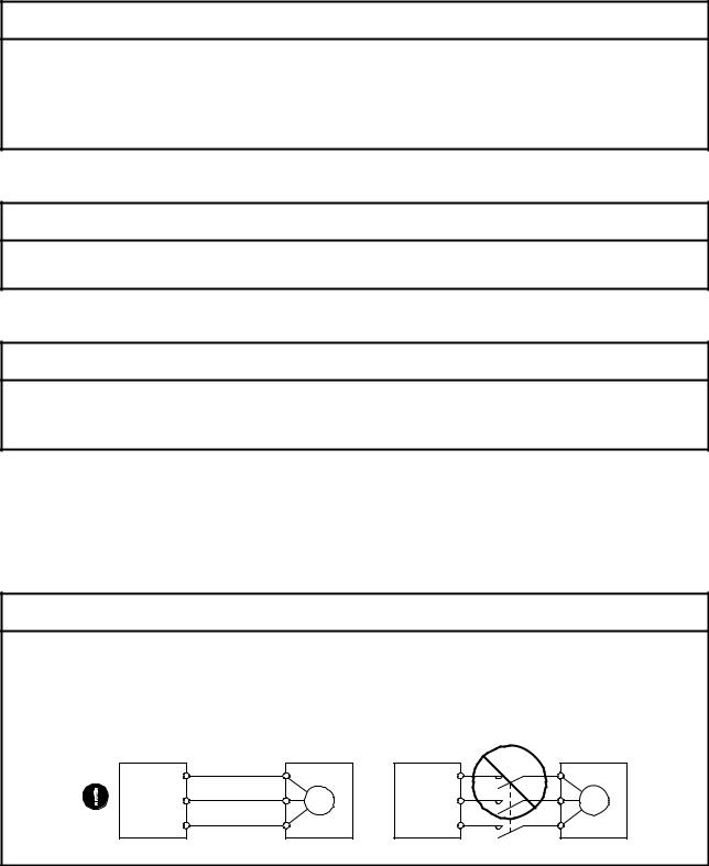
 Connect the servo amplifier power output (U, V, and W) to the servo motor power input (U, V, and W) directly. Do not let a magnetic contactor, etc. intervene. Otherwise, it may cause a malfunction.
|
Servo amplifier |
U |
Servo motor |
Servo amplifier |
U |
Servo motor |
|
U |
U |
||||
|
V |
V |
M |
V |
V |
M |
|
W |
W |
W |
W |
||
A — 2
(2) Usage
 CAUTION
 Before resetting an alarm, make sure that the run signal of the servo amplifier is off in order to prevent a sudden restart. Otherwise, it may cause an accident.
 Use the servo amplifier with the specified servo motor.
(3) Corrective actions
 CAUTION
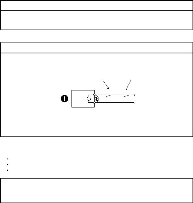
 When it is assumed that a hazardous condition may occur due to a power failure or product malfunction, use a servo motor with an electromagnetic brake or external brake to prevent the condition.
 Configure an electromagnetic brake circuit so that it is activated also by an external EMG stop switch.
|
Contacts must be opened when CALM (Common |
Contacts must be opened |
|
malfunction) or MBR (Electromagnetic brake |
with the EMG stop switch. |
|
interlock) turns off. |
Servo motor
Electromagnetic brake
 When any alarm has occurred, eliminate its cause, ensure safety, and deactivate the alarm before restarting operation.
 Provide an adequate protection to prevent unexpected restart after an instantaneous power failure.
<<About the manual>>
This Instruction Manual covers the following models.
MR-J4-_A
MR-J4-_B
MR-J4W_-_B
The symbols in the target column mean as follows.
MR-J4-_A: [A]
MR-J4-_B: [B]
MR-J4W_-_B: [WB]
A — 3

MEMO
A — 4
CONTENTS |
||
|
1. TROUBLESHOOTING |
1- 1 to 1-54 |
|
|
1.1 |
Alarm and warning list………………………………………………………………………………………………………… |
1- 1 |
|
1.2 |
Remedies for alarms………………………………………………………………………………………………………….. |
1- 5 |
|
1.3 |
Remedies for warnings ……………………………………………………………………………………………………… |
1-44 |
|
APPENDIX |
App.- 1 to App.- 1 |
|
|
App. 1 Detection points of [AL. 25], [AL. 92], and [AL. 9F] ……………………………………………………….. |
App.- 1 |
1

MEMO
2

1. TROUBLESHOOTING
1. TROUBLESHOOTING
1.1 Alarm and warning list
When an error occurs during operation, the corresponding alarm or warning is displayed. If any alarm or warning has occurred, refer to section 1.2 and take the appropriate action. When an alarm occurs, ALM (Malfunction) will turn off.
Alarm
|
No. |
Name |
Detail |
Detail name |
||
|
display |
|||||
|
10 |
Undervoltage |
10.1 |
Voltage drop in the control power |
||
|
10.2 |
Voltage drop in the main circuit power |
||||
|
11 |
Switch setting error |
11.1 |
Axis number setting error |
||
|
11.2 |
Disabling control axis setting error |
||||
|
12 |
Memory error 1 (RAM) |
12.1 |
RAM error 1 |
||
|
12.2 |
RAM error 2 |
||||
|
12.3 |
RAM error 3 |
||||
|
12.4 |
RAM error 4 |
||||
|
12.5 |
RAM error 5 |
||||
|
13 |
Clock error |
13.1 |
Clock error 1 |
||
|
13.2 |
Clock error 2 |
||||
|
14 |
Control process error |
14.1 |
Control process error 1 |
||
|
14.2 |
Control process error 2 |
||||
|
14.3 |
Control process error 3 |
||||
|
14.4 |
Control process error 4 |
||||
|
14.5 |
Control process error 5 |
||||
|
14.6 |
Control process error 6 |
||||
|
14.7 |
Control process error 7 |
||||
|
14.8 |
Control process error 8 |
||||
|
14.9 |
Control process error 9 |
||||
|
14.A |
Control process error 10 |
||||
|
15 |
Memory error 2 (EEP-ROM) |
15.1 |
EEP-ROM error at power on |
||
|
15.2 |
EEP-ROM error during operation |
||||
|
16 |
Encoder |
initial |
communication |
16.1 |
Encoder initial communication — Receive data error 1 |
|
error 1 |
16.2 |
Encoder initial communication — Receive data error 2 |
|||
|
16.3 |
Encoder initial communication — Receive data error 3 |
||||
|
16.5 |
Encoder initial communication — Transmission data error 1 |
||||
|
16.6 |
Encoder initial communication — Transmission data error 2 |
||||
|
16.7 |
Encoder initial communication — Transmission data error 3 |
||||
|
16.A |
Encoder initial communication — Process error 1 |
||||
|
16.B |
Encoder initial communication — Process error 2 |
||||
|
16.C |
Encoder initial communication — Process error 3 |
||||
|
16.D |
Encoder initial communication — Process error 4 |
||||
|
16.E |
Encoder initial communication — Process error 5 |
||||
|
16.F |
Encoder initial communication — Process error 6 |
||||
|
17 |
Board error |
17.1 |
Board error 1 |
||
|
17.3 |
Board error 2 |
||||
|
17.4 |
Board error 3 |
||||
|
17.5 |
Board error 4 |
||||
|
17.6 |
Board error 5 |
||||
|
19 |
Memory error 3 (Flash-ROM) |
19.1 |
Flash-ROM error 1 |
||
|
19.2 |
Flash-ROM error 2 |
||||
|
1A |
Servo motor combination error |
1A.1 |
Servo motor combination error |
||
|
1A.2 |
Servo motor control mode combination error |
||||
|
1E |
Encoder |
initial |
communication |
1E.1 |
Encoder malfunction |
|
error 2 |
|||||
|
1F |
Encoder |
initial |
communication |
1F.1 |
Incompatible encoder |
|
error 3 |
|||||
1 — 1

1. TROUBLESHOOTING
Alarm
|
No. |
Name |
Detail |
Detail name |
|||
|
display |
||||||
|
20 |
Encoder |
normal |
communication |
20.1 |
Encoder normal communication — Receive data error 1 |
|
|
error 1 |
20.2 |
Encoder normal communication — Receive data error 2 |
||||
|
20.3 |
Encoder normal communication — Receive data error 3 |
|||||
|
20.5 |
Encoder normal communication — Transmission data error 1 |
|||||
|
20.6 |
Encoder normal communication — Transmission data error 2 |
|||||
|
20.7 |
Encoder normal communication — Transmission data error 3 |
|||||
|
20.9 |
Encoder normal communication — Receive data error 4 |
|||||
|
20.A |
Encoder normal communication — Receive data error 5 |
|||||
|
21 |
Encoder |
normal |
communication |
21.1 |
Encoder data error 1 |
|
|
error 2 |
21.2 |
Encoder data update error |
||||
|
21.3 |
Encoder data waveform error |
|||||
|
21.4 |
Encoder non-signal error |
|||||
|
21.5 |
Encoder hardware error 1 |
|||||
|
21.6 |
Encoder hardware error 2 |
|||||
|
21.9 |
Encoder data error 2 |
|||||
|
24 |
Main circuit error |
24.1 |
Ground fault detected by hardware detection circuit |
|||
|
24.2 |
Ground fault detected by software detection function |
|||||
|
25 |
Absolute position erased |
25.1 |
Servo motor encoder — Absolute position erased |
|||
|
27 |
Initial |
magnetic |
pole detection |
27.1 |
Magnetic pole detection — Abnormal termination |
|
|
error |
27.2 |
Magnetic pole detection — Time out error |
||||
|
27.3 |
Magnetic pole detection — Limit switch error |
|||||
|
27.4 |
Magnetic pole detection — Estimated error |
|||||
|
27.5 |
Magnetic pole detection — Position deviation error |
|||||
|
27.6 |
Magnetic pole detection — Speed deviation error |
|||||
|
27.7 |
Magnetic pole detection — Current error |
|||||
|
28 |
Linear encoder error 2 |
28.1 |
Linear encoder — Environment error |
|||
|
2A |
Linear encoder error 1 |
2A.1 |
Linear encoder error 1-1 |
|||
|
2A.2 |
Linear encoder error 1-2 |
|||||
|
2A.3 |
Linear encoder error 1-3 |
|||||
|
2A.4 |
Linear encoder error 1-4 |
|||||
|
2A.5 |
Linear encoder error 1-5 |
|||||
|
2A.6 |
Linear encoder error 1-6 |
|||||
|
2A.7 |
Linear encoder error 1-7 |
|||||
|
2A.8 |
Linear encoder error 1-8 |
|||||
|
2B |
Encoder counter error |
2B.1 |
Encoder counter error 1 |
|||
|
2B.2 |
Encoder counter error 2 |
|||||
|
30 |
Regenerative error |
30.1 |
Regeneration heat error |
|||
|
30.2 |
Regeneration signal error |
|||||
|
30.3 |
Regeneration feedback signal error |
|||||
|
31 |
Overspeed |
31.1 |
Abnormal motor speed |
|||
|
32 |
Overcurrent |
32.1 |
Overcurrent detected at hardware detection circuit (during operation) |
|||
|
32.2 |
Overcurrent detected at software detection function (during operation) |
|||||
|
32.3 |
Overcurrent detected at hardware detection circuit (during a stop) |
|||||
|
32.4 |
Overcurrent detected at software detection function (during a stop) |
|||||
|
33 |
Overvoltage |
33.1 |
Main circuit voltage error |
|||
|
34 |
SSCNET receive error 1 |
34.1 |
SSCNET receive data error |
|||
|
34.2 |
SSCNET connector connection error |
|||||
|
34.3 |
SSCNET communication data error |
|||||
|
34.4 |
Hardware error signal detection |
|||||
|
35 |
Command frequency error |
35.1 |
Command frequency error |
|||
|
36 |
SSCNET receive error 2 |
36.1 |
Continuous communication data error |
|||
|
37 |
Parameter error |
37.1 |
Parameter setting range error |
|||
|
37.2 |
Parameter combination error |
|||||
|
3A |
Inrush |
current suppression circuit |
3A.1 |
Inrush current suppression circuit error |
||
|
error |
||||||
|
3E |
Operation mode error |
3E.1 |
Operation mode error |
|||
1 — 2

1. TROUBLESHOOTING
Alarm
|
No. |
Name |
Detail |
Detail name |
|
|
display |
||||
|
42 |
Servo control error |
42.1 |
Servo control error by position deviation |
|
|
42.2 |
Servo control error by speed deviation |
|||
|
42.3 |
Servo control error by torque/thrust deviation |
|||
|
45 |
Main circuit device overheat |
45.1 |
Main circuit device overheat error |
|
|
46 |
Servo motor overheat |
46.1 |
Abnormal temperature of servo motor 1 |
|
|
46.2 |
Abnormal temperature of servo motor 2 |
|||
|
46.3 |
Thermistor disconnected |
|||
|
46.5 |
Abnormal temperature of servo motor 3 |
|||
|
46.6 |
Abnormal temperature of servo motor 4 |
|||
|
47 |
Cooling fan error |
47.1 |
Cooling fan stop error |
|
|
47.2 |
Cooling fan speed reduction error |
|||
|
50 |
Overload 1 |
50.1 |
Thermal overload error 1 during operation |
|
|
50.2 |
Thermal overload error 2 during operation |
|||
|
50.3 |
Thermal overload error 4 during operation |
|||
|
50.4 |
Thermal overload error 1 during a stop |
|||
|
50.5 |
Thermal overload error 2 during a stop |
|||
|
50.6 |
Thermal overload error 4 during a stop |
|||
|
51 |
Overload 2 |
51.1 |
Thermal overload error 3 during operation |
|
|
51.2 |
Thermal overload error 3 during a stop |
|||
|
52 |
Error excessive |
52.1 |
Excess droop pulse 1 |
|
|
52.3 |
Excess droop pulse 2 |
|||
|
52.4 |
Error excessive during 0 torque limit |
|||
|
52.5 |
Excess droop pulse 3 |
|||
|
54 |
Oscillation detection |
54.1 |
Oscillation detection error |
|
|
56 |
Forced stop error |
56.2 |
Over speed during forced stop |
|
|
56.3 |
Estimated distance over during forced stop |
|||
|
63 |
STO timing error |
63.1 |
STO1 off |
|
|
63.2 |
STO2 off |
|||
|
8A |
USB communication time-out error |
8A.1 |
USB communication time-out error |
|
|
8E |
USB communication error |
8E.1 |
USB communication receive error |
|
|
8E.2 |
USB communication checksum error |
|||
|
8E.3 |
USB communication character error |
|||
|
8E.4 |
USB communication command error |
|||
|
8E.5 |
USB communication data number error |
|||
|
888/ |
Watchdog |
88._/ |
Watchdog |
|
|
88888 |
8888._ |
|||
1 — 3
![]()
1. TROUBLESHOOTING
Warning
|
No. |
Name |
Detail |
Detail name |
||
|
display |
|||||
|
91 |
Servo amplifier overheat warning |
91.1 |
Main circuit device overheat warning |
||
|
92 |
Battery |
cable |
disconnection |
92.1 |
Encoder battery cable disconnection warning |
|
warning |
92.3 |
Battery degradation |
|||
|
95 |
STO warning |
95.1 |
STO1 off detection |
||
|
95.2 |
STO2 off detection |
||||
|
96 |
Home position setting warning |
96.1 |
In-position warning at home positioning |
||
|
96.2 |
Command input warning at home positioning |
||||
|
96.3 |
Servo off warning at home positioning |
||||
|
99 |
Stroke limit warning |
99.1 |
Forward rotation stroke end off |
||
|
99.2 |
Reverse rotation stroke end off |
||||
|
9F |
Battery warning |
9F.1 |
Low battery |
||
|
9F.2 |
Battery degradation warning |
||||
|
E0 |
Excessive regeneration warning |
E0.1 |
Excessive regeneration warning |
||
|
E1 |
Overload warning 1 |
E1.1 |
Thermal overload warning 1 during operation |
||
|
E1.2 |
Thermal overload warning 2 during operation |
||||
|
E1.3 |
Thermal overload warning 3 during operation |
||||
|
E1.4 |
Thermal overload warning 4 during operation |
||||
|
E1.5 |
Thermal overload error 1 during a stop |
||||
|
E1.6 |
Thermal overload error 2 during a stop |
||||
|
E1.7 |
Thermal overload error 3 during a stop |
||||
|
E1.8 |
Thermal overload error 4 during a stop |
||||
|
E2 |
Servo motor overheat warning |
E2.1 |
Servo motor temperature warning |
||
|
E3 |
Absolute position counter warning |
E3.1 |
Multi-revolution counter travel distance excess warning |
||
|
E3.2 |
Encoder absolute positioning counter warning |
||||
|
E3.5 |
Absolute position counter warning |
||||
|
E4 |
Parameter warning |
E4.1 |
Parameter setting range error warning |
||
|
E5 |
ABS time-out warning |
E5.1 |
Time-out during ABS data transfer |
||
|
E5.2 |
ABSM off during ABS data transfer |
||||
|
E5.3 |
SON off during ABS data transfer |
||||
|
E6 |
Servo forced stop warning |
E6.1 |
Forced stop warning |
||
|
E7 |
Controller forced stop warning |
E7.1 |
Controller forced stop warning |
||
|
E8 |
Cooling |
fan speed reduction |
E8.1 |
Decreased cooling fan speed warning |
|
|
warning |
|||||
|
E9 |
Main circuit off warning |
E9.1 |
Servo-on signal on during main circuit off |
||
|
E9.2 |
Bus voltage drop during low speed operation |
||||
|
E9.3 |
Ready-on signal on during main circuit off |
||||
|
EA |
ABS servo-on warning |
EA.1 |
ABS servo-on warning |
||
|
EB |
The other axis error warning |
EB.1 |
The other axis error warning |
||
|
EC |
Overload warning 2 |
EC.1 |
Overload warning 2 |
||
|
ED |
Output watt excess warning |
ED.1 |
Output watt excess warning |
||
|
F0 |
Tough drive warning |
F0.1 |
Instantaneous power failure tough drive warning |
||
|
F0.3 |
Vibration tough drive warning |
||||
|
F2 |
Drive recorder — Miswriting warning |
F2.1 |
Drive recorder — Area writing time-out warning |
||
|
F2.2 |
Drive recorder — Data miswriting warning |
||||
|
F3 |
Oscillation detection warning |
F3.1 |
Oscillation detection warning |
||
1 — 4
1. TROUBLESHOOTING
1.2 Remedies for alarms
 When any alarm has occurred, eliminate its cause, ensure safety, and deactivate the alarm before restarting operation. Otherwise, it may cause injury.
CAUTION If [AL. 25 Absolute position erased] occurs, always make home position setting again. Otherwise, it may cause an unexpected operation.
 As soon as an alarm occurs, make the Servo-off status and interrupt the main circuit power.
POINT
 When any of the following alarms has occurred, do not cycle the power repeatedly to restart. Doing so will cause a malfunction of the servo amplifier and the servo motor. Remove its cause and allow about 30 minutes for cooling before resuming the operation.
[AL. 30 Regenerative error] • [AL. 45 Main circuit device overheat] [AL. 46 Servo motor overheat] • [AL. 50 Overload 1]
[AL. 51 Overload 2]
Remove the cause of the alarm in accordance with this section. Use MR Configurator2 to refer to a factor of alarm occurrence.
1 — 5

1. TROUBLESHOOTING
|
Alarm No.: 10 |
Name: Undervoltage |
||||||
|
Alarm content |
The voltage of the control circuit power supply has dropped. |
||||||
|
The voltage of the main circuit power supply has dropped. |
|||||||
|
Displ |
Detail name |
Cause |
Check method |
Check result |
Action |
Targe |
|
|
ay |
t |
||||||
|
10.1 |
Voltage drop in |
(1) |
The connection of the |
Check the control |
It has a failure. |
Connect it correctly. |
[A] |
|
the control |
control circuit power |
circuit power supply |
[B] |
||||
|
power |
supply connector |
connector. |
[WB] |
||||
|
(CNP2) has a failure. |
It has no failure. |
Check (2). |
|||||
|
(2) |
The voltage of the |
Check if the voltage |
The voltage is lower |
Review the voltage of |
|||
|
control circuit power |
of the control circuit |
than 160 V AC. |
the control circuit |
||||
|
supply is low. |
power supply is lower |
power supply. |
|||||
|
than 160 V AC. |
The voltage is higher |
Check (3). |
|||||
|
than 160 V AC. |
|||||||
|
(3) |
An instantaneous |
Check if the power |
It has a problem. |
Review the power. |
|||
|
power failure has |
has a problem. |
||||||
|
occurred for longer |
|||||||
|
time than the specified |
|||||||
|
time. The time will be |
|||||||
|
60 ms when [Pr. PA20] |
|||||||
|
is «_ 0 _ _». The time |
|||||||
|
will be the value set in |
|||||||
|
[Pr. PF25] when [Pr. |
|||||||
|
PA20] is «_ 1 _ _». |
|||||||
|
10.2 |
Voltage drop in |
(1) |
The main circuit power |
Check the main |
It is disconnected. |
Connect it correctly. |
|
|
the main circuit |
supply connector |
circuit power supply |
|||||
|
power |
(CNP1) was |
connector. |
|||||
|
disconnected. |
|||||||
|
It is connected. |
Check (2). |
||||||
|
(2) |
The voltage of the main |
Check if the voltage |
The voltage is lower |
Increase the voltage |
|||
|
circuit power supply is |
of the main circuit |
than 160 V AC. |
of the main circuit |
||||
|
low. |
power supply is lower |
power supply. |
|||||
|
than 160 V AC. |
The voltage is higher |
Check (3). |
|||||
|
than 160 V AC. |
|||||||
|
(3) |
The alarm has |
Check that the bus |
The voltage is less |
Increase the |
|||
|
occurred during |
voltage during |
than 200 V DC. |
acceleration time |
||||
|
acceleration. |
acceleration is 200 V |
constant. Or increase |
|||||
|
DC or more. |
the power supply |
||||||
|
capacity. |
|||||||
|
The voltage is 200 V |
Check (4). |
||||||
|
DC or more. |
|||||||
|
(4) |
The servo amplifier is |
Check the bus |
The voltage of the |
Replace the servo |
|||
|
malfunctioning. |
voltage value. |
main circuit power |
amplifier. |
||||
|
supply is 160 V AC or |
|||||||
|
more, and the bus |
|||||||
|
voltage is less than |
|||||||
|
200 V DC. |
1 — 6
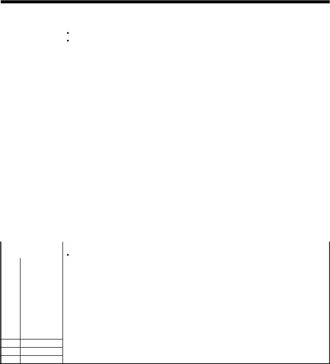
1. TROUBLESHOOTING
|
Alarm No.: 11 |
Name: Switch setting error |
||||||||
|
Alarm content |
The setting of the axis selection rotary switch or auxiliary axis number setting switch is incorrect. |
||||||||
|
The setting of the disabling control axis switch is incorrect. |
|||||||||
|
Displ |
Detail name |
Cause |
Check method |
Check result |
Action |
Targe |
|||
|
ay |
t |
||||||||
|
11.1 |
Axis number |
(1) |
The setting of the Axis |
Check the settings of |
When both of the |
Set the axis No. |
[WB] |
||
|
setting error |
No. is incorrect. |
the auxiliary axis |
auxiliary axis number |
correctly. |
|||||
|
number setting switch |
setting switches are |
||||||||
|
(SW2) and axis |
on, check the axis |
||||||||
|
selection rotary switch |
selection rotary switch |
||||||||
|
(SW1). |
if «E» is selected for |
||||||||
|
MR-J4W2, («E» or «F» |
|||||||||
|
is selected for MR- |
|||||||||
|
J4W2). |
|||||||||
|
Both of the auxiliary |
Replace the servo |
||||||||
|
axis number setting |
amplifier. |
||||||||
|
switches are off. |
|||||||||
|
11.2 |
Disabling |
(1) |
The setting of the |
Check the setting of |
Check if the setting is |
Set it correctly. |
|||
|
control axis |
disabling control axis |
the disabling control |
as follows. |
||||||
|
setting error |
switch is incorrect. |
axis switch. |
1) |
Only A-axis is |
|||||
|
disabled. |
|||||||||
|
2) |
Only B-axis is |
||||||||
|
disabled. |
|||||||||
|
3) |
A-axis and B-axis |
||||||||
|
are disabled. |
|||||||||
|
4) |
A-axis and C-axis |
||||||||
|
are disabled. |
|||||||||
|
The setting is other |
Replace the servo |
||||||||
|
than above. |
amplifier. |
||||||||
|
Alarm No.: 12 |
Name: Memory error 1 (RAM) |
||||||||
|
Alarm content |
A part (RAM) in the servo amplifier is failure. |
||||||||
|
Displ |
Detail name |
Cause |
Check method |
Check result |
Action |
Targe |
|||
|
ay |
t |
||||||||
|
12.1 |
RAM error 1 |
(1) |
A part in the servo |
Disconnect the cables |
It is repeatable. |
Replace the servo |
[A] |
||
|
amplifier is failure. |
except the control |
amplifier. |
[B] |
||||||
|
circuit power supply, |
It is not repeatable. |
Check (2). |
[WB] |
||||||
|
and then check the |
|||||||||
|
repeatability. |
|||||||||
|
(2) |
Something near the |
Check the power |
It has a failure. |
Take |
|||||
|
device caused it. |
supply for noise. |
countermeasures |
|||||||
|
against its cause. |
12.2RAM error 2 Check it with the check method for [AL. 12.1].
12.3RAM error 3
12.4RAM error 4
12.5RAM error 5
1 — 7

1. TROUBLESHOOTING
|
Alarm No.: 13 |
Name: Clock error |
||||||
|
Alarm content |
A part in the servo amplifier is failure. |
||||||
|
A clock error transmitted from the controller occurred. |
|||||||
|
Displ |
Detail name |
Cause |
Check method |
Check result |
Action |
Targe |
|
|
ay |
t |
||||||
|
13.1 |
Clock error 1 |
(1) |
A part in the servo |
Disconnect the cables |
It is repeatable. |
Replace the servo |
[A] |
|
amplifier is failure. |
except the control |
amplifier. |
[B] |
||||
|
circuit power supply, |
It is not repeatable. |
Check (2). |
[WB] |
||||
|
and then check the |
|||||||
|
repeatability. |
|||||||
|
(2) |
A clock error |
Check if the error |
It occurs. |
Replace the |
[B] |
||
|
transmitted from the |
occurs when you |
controller. |
[WB] |
||||
|
controller occurred. |
connect the amplifier |
It does not occur. |
Check (3). |
||||
|
to the controller. |
|||||||
|
(3) |
The servo amplifier of |
Check if the servo |
It is malfunctioning. |
Replace the servo |
|||
|
the next axis is |
amplifier of the next |
amplifier of the next |
|||||
|
malfunctioning. |
axis is malfunctioning. |
axis. |
|||||
|
It is not |
Check (4). |
||||||
|
malfunctioning. |
|||||||
|
(4) |
Something near the |
Check the power |
It has a failure. |
Take |
[A] |
||
|
device caused it. |
supply for noise. |
countermeasures |
[B] |
||||
|
Check if the |
against its cause. |
[WB] |
|||||
|
connector is shorted. |
|||||||
|
13.2 |
Clock error 2 |
Check it with the check method for [AL. 13.1]. |
1 — 8

1. TROUBLESHOOTING
|
Alarm No.: 14 |
Name: Control process error |
||||||
|
Alarm content |
The process did not complete within the specified time. |
||||||
|
Displ |
Detail name |
Cause |
Check method |
Check result |
Action |
Targe |
|
|
ay |
t |
||||||
|
14.1 |
Control |
(1) |
The parameter setting |
Check if the |
It is incorrect. |
Set it correctly. |
[A] |
|
process error 1 |
is incorrect. |
parameter setting is |
[B] |
||||
|
incorrect. |
[WB] |
||||||
|
It is correct. |
Check (2). |
||||||
|
(2) |
Something near the |
Check the power |
It has a failure. |
Take |
|||
|
device caused it. |
supply for noise. |
countermeasures |
|||||
|
Check if the |
against its cause. |
||||||
|
connector is shorted. |
It has no failure. |
Check (3). |
|||||
|
(3) |
The servo amplifier is |
Replace the servo |
It is not repeatable. |
Replace the servo |
|||
|
malfunctioning. |
amplifier, and then |
amplifier. |
|||||
|
check the |
|||||||
|
repeatability. |
|||||||
|
14.2 |
Control |
(1) |
A synchronous signal |
Replace the |
It is repeatable. |
Replace the servo |
[B] |
|
process error 2 |
error transmitted from |
controller, and then |
amplifier. |
[WB] |
|||
|
the controller occurred. |
check the |
It is not repeatable. |
Check (2). |
||||
|
repeatability. |
|||||||
|
(2) |
The parameter setting |
Check if the |
It is incorrect. |
Set it correctly. |
[A] |
||
|
is incorrect. |
parameter setting is |
[B] |
|||||
|
incorrect. |
[WB] |
||||||
|
It is correct. |
Check (3). |
||||||
|
(3) |
Something near the |
Check the power |
It has a failure. |
Take |
|||
|
device caused it. |
supply for noise. |
countermeasures |
|||||
|
Check if the |
against its cause. |
||||||
|
connector is shorted. |
It has no failure. |
Check (4). |
|||||
|
(4) |
The servo amplifier is |
Replace the servo |
It is not repeatable. |
Replace the servo |
|||
|
malfunctioning. |
amplifier, and then |
amplifier. |
|||||
|
check the |
|||||||
|
repeatability. |
|||||||
|
14.3 |
Control |
Check it with the check method for [AL. 14.1]. |
|||||
|
process error 3 |
|||||||
|
14.4 |
Control |
||||||
|
process error 4 |
|||||||
|
14.5 |
Control |
||||||
|
process error 5 |
|||||||
|
14.6 |
Control |
||||||
|
process error 6 |
|||||||
|
14.7 |
Control |
||||||
|
process error 7 |
|||||||
|
14.8 |
Control |
||||||
|
process error 8 |
|||||||
|
14.9 |
Control |
||||||
|
process error 9 |
|||||||
|
14.A |
Control process |
||||||
|
error 10 |
1 — 9

1. TROUBLESHOOTING
|
Alarm No.: 15 |
Name: Memory error 2 (EEP-ROM) |
||||||
|
Alarm content |
A part (EEP-ROM) in the servo amplifier is failure. |
||||||
|
Displ |
Detail name |
Cause |
Check method |
Check result |
Action |
Targe |
|
|
ay |
t |
||||||
|
15.1 |
EEP-ROM error |
(1) |
EEP-ROM is |
Disconnect the cables |
It is repeatable. |
Replace the servo |
[A] |
|
at power on |
malfunctioning at power |
except the control |
amplifier. |
[B] |
|||
|
on. |
circuit power supply, |
It is not repeatable. |
Check (2). |
[WB] |
|||
|
and then check the |
|||||||
|
repeatability. |
|||||||
|
(2) |
Something near the |
Check the power |
It has a failure. |
Take |
|||
|
device caused it. |
supply for noise. |
countermeasures |
|||||
|
Check if the connector |
against its cause. |
||||||
|
is shorted. |
It has no failure. |
Check (3). |
|||||
|
(3) |
The number of write |
Check if parameters |
It has a failure. |
Replace the servo |
|||
|
times exceeded |
has been used very |
amplifier. Change the |
|||||
|
100,000. |
frequently. |
process to use |
|||||
|
parameters less |
|||||||
|
frequently after |
|||||||
|
replacement. |
|||||||
|
15.2 |
EEP-ROM error |
(1) |
EEP-ROM is |
Check if the error |
It occurs. |
Replace the servo |
|
|
during operation |
malfunctioning during |
occurs when you |
amplifier. |
||||
|
normal operation. |
change parameters |
It does not occur. |
Check (2). |
||||
|
during normal |
|||||||
|
operation. |
|||||||
|
(2) |
A write error occurred |
Check if the alarm |
It takes an hour or |
Replace the servo |
|||
|
while tuning results was |
occurs after an hour |
more. |
amplifier. |
||||
|
processed. |
from power on. |
It takes less than an |
Check (3). |
||||
|
hour. |
|||||||
|
(3) |
Something near the |
Check the power |
It has a failure. |
Take |
|||
|
device caused it. |
supply for noise. |
countermeasures |
|||||
|
Check if the connector |
against its cause. |
||||||
|
is shorted. |
|||||||
|
Alarm No.: 16 |
Name: Encoder initial communication error 1 |
||||||
|
Alarm content |
Communication error occurred between encoder and servo amplifier. |
||||||
|
Displ |
Detail name |
Cause |
Check method |
Check result |
Action |
Targe |
|
|
ay |
t |
||||||
|
16.1 |
Encoder initial |
(1) |
An encoder cable is |
Check if the encoder |
It has a failure. |
Replace or repair the |
[A] |
|
communication |
malfunctioning. |
cable is disconnected |
cable. |
[B] |
|||
|
— Receive data |
or shorted. |
[WB] |
|||||
|
error 1 |
|||||||
|
It has no failure. |
Check (2). |
||||||
|
(2) |
The servo amplifier is |
Replace the servo |
It is not repeatable. |
Replace the servo |
|||
|
malfunctioning. |
amplifier, and then |
amplifier. |
|||||
|
check the |
It is repeatable. |
Check (3). |
|||||
|
repeatability. |
|||||||
|
(3) |
An encoder is |
Replace the servo |
It is not repeatable. |
Replace the servo |
|||
|
malfunctioning. |
motor or linear |
motor. |
|||||
|
encoder, and then |
It is repeatable. |
Check (4). |
|||||
|
check the |
|||||||
|
repeatability. |
|||||||
|
(4) |
Something near the |
Check the noise, |
It has a failure. |
Take |
|||
|
device caused it. |
ambient temperature, |
countermeasures |
|||||
|
vibration, etc. |
against its cause. |
||||||
|
16.2 |
Encoder initial |
Check it with the check method for [AL. 16.1]. |
|||||
|
communication |
|||||||
|
— Receive data |
|||||||
|
error 2 |
1 — 10

1. TROUBLESHOOTING
|
Alarm No.: 16 |
Name: Encoder initial communication error 1 |
||||||
|
Alarm content |
Communication error occurred between encoder and servo amplifier. |
||||||
|
Displ |
Detail name |
Cause |
Check method |
Check result |
Action |
Targe |
|
|
ay |
t |
||||||
|
16.3 |
Encoder initial |
(1) |
An axis not used is not |
Check the setting of |
It is not set as |
Set it as disabled- |
[WB] |
|
communication — |
set as disabled-axis. |
the disabling control |
disabled-axis. |
axis. |
|||
|
Receive data |
axis switch (SW2). |
||||||
|
error 3 |
It is set as disabled- |
Check (2). |
|||||
|
axis. |
|||||||
|
(2) |
An encoder cable was |
Check if the encoder |
It is not connected. |
Connect it correctly. |
[A] |
||
|
disconnected. |
cable is connected |
[B] |
|||||
|
correctly. |
It is connected. |
Check (3). |
[WB] |
||||
|
(3) |
The parameter setting |
Check the parameter |
The setting is |
Set it correctly. |
|||
|
of two-wire type/four- |
setting. |
incorrect. |
|||||
|
wire type is incorrect. |
|||||||
|
The setting is correct. |
Check (4). |
||||||
|
Type A: [Pr. PC22] |
|||||||
|
Type B: [Pr. PC04] |
|||||||
|
(4) |
An encoder cable is |
Check if the encoder |
It has a failure. |
Replace or repair the |
|||
|
malfunctioning. |
cable is disconnected |
cable. |
|||||
|
or shorted. |
It has no failure. |
Check (5). |
|||||
|
(5) |
The voltage of the |
Check the voltage of |
The control circuit |
Review the power |
|||
|
control circuit power |
the control circuit |
power supply has |
and related parts. |
||||
|
supply has been |
power supply. |
been an |
|||||
|
unstable. |
instantaneous power |
||||||
|
failure. |
|||||||
|
It has no failure. |
Check (6). |
||||||
|
(6) |
The servo amplifier is |
Replace the servo |
It is not repeatable. |
Replace the servo |
|||
|
malfunctioning. |
amplifier, and then |
amplifier. |
|||||
|
check the |
It is repeatable. |
Check (7). |
|||||
|
repeatability. |
|||||||
|
(7) |
An encoder is |
Replace the servo |
It is not repeatable. |
Replace the servo |
|||
|
malfunctioning. |
motor, and then |
motor. |
|||||
|
check the |
It is repeatable. |
Check (8). |
|||||
|
repeatability. |
|||||||
|
(8) |
Something near the |
Check the noise, |
It has a failure. |
Take |
|||
|
device caused it. |
ambient temperature, |
countermeasures |
|||||
|
vibration, etc. |
against its cause. |
||||||
|
16.5 |
Encoder initial |
Check it with the check method for [AL. 16.1]. |
|||||
|
communication — |
|||||||
|
Transmission |
|||||||
|
data error 1 |
|||||||
|
16.6 |
Encoder initial |
||||||
|
communication — |
|||||||
|
Transmission |
|||||||
|
data error 2 |
|||||||
|
16.7 |
Encoder initial |
||||||
|
communication — |
|||||||
|
Transmission |
|||||||
|
data error 3 |
1 — 11

1. TROUBLESHOOTING
|
Alarm No.: 16 |
Name: Encoder initial communication error 1 |
||||||
|
Alarm content |
Communication error occurred between encoder and servo amplifier. |
||||||
|
Displ |
Detail name |
Cause |
Check method |
Check result |
Action |
Targe |
|
|
ay |
t |
||||||
|
16.A |
Encoder initial |
(1) |
The servo amplifier is |
Replace the servo |
It is not repeatable. |
Replace the servo |
[A] |
|
communication — |
malfunctioning. |
amplifier, and then |
amplifier. |
[B] |
|||
|
Process error 1 |
check the |
[WB] |
|||||
|
repeatability. |
It is repeatable. |
Check (2). |
|||||
|
(2) |
An encoder is |
Replace the servo |
It is not repeatable. |
Replace the servo |
|||
|
malfunctioning. |
motor, and then check |
motor. |
|||||
|
the repeatability. |
It is repeatable. |
Check (3). |
|||||
|
(3) |
Something near the |
Check the noise, |
It has a failure. |
Take |
|||
|
device caused it. |
ambient temperature, |
countermeasures |
|||||
|
vibration, etc. |
against its cause. |
||||||
|
16.B |
Encoder initial |
Check it with the check method for [AL. 16.A]. |
|||||
|
communication — |
|||||||
|
Process error 2 |
|||||||
|
16.C |
Encoder initial |
||||||
|
communication — |
|||||||
|
Process error 3 |
|||||||
|
16.D |
Encoder initial |
||||||
|
communication — |
|||||||
|
Process error 4 |
|||||||
|
16.E |
Encoder initial |
||||||
|
communication — |
|||||||
|
Process error 5 |
|||||||
|
16.F |
Encoder initial |
||||||
|
communication — |
|||||||
|
Process error 6 |
1 — 12

1. TROUBLESHOOTING
|
Alarm No.: 17 |
Name: Board error |
||||||
|
Alarm content |
A part in the servo amplifier is malfunctioning. |
||||||
|
Displ |
Detail name |
Cause |
Check method |
Check result |
Action |
Targe |
|
|
ay |
t |
||||||
|
17.1 |
Board error 1 |
(1) |
A current detection |
Check if the alarm |
It occurs. |
Replace the servo |
[A] |
|
circuit is |
occurs during the |
amplifier. |
[B] |
||||
|
malfunctioning. |
servo-on status. |
[WB] |
|||||
|
It does not occur. |
Check (2). |
||||||
|
(2) |
Something near the |
Check the noise, |
It has a failure. |
Take |
|||
|
device caused it. |
ambient temperature, |
countermeasures |
|||||
|
etc. |
against its cause. |
||||||
|
17.3 |
Board error 2 |
Check it with the check method for [AL. 17.1]». |
|||||
|
17.4 |
Board error 3 |
(1) |
The servo amplifier |
Disconnect the cables |
It is repeatable. |
Replace the servo |
|
|
recognition signal was |
except the control |
amplifier. |
|||||
|
not read properly. |
circuit power supply, |
It is not repeatable. |
Check (2). |
||||
|
and then check the |
|||||||
|
repeatability. |
|||||||
|
(2) |
Something near the |
Check the noise, |
It has a failure. |
Take |
|||
|
device caused it. |
ambient temperature, |
countermeasures |
|||||
|
etc. |
against its cause. |
||||||
|
17.5 |
Board error 4 |
(1) |
The setting value of the |
Disconnect the cables |
It is repeatable. |
Replace the servo |
[B] |
|
rotary switch (SW1) |
except the control |
amplifier. |
[WB] |
||||
|
was not read properly. |
circuit power supply, |
It is not repeatable. |
Check (2). |
||||
|
and then check the |
|||||||
|
repeatability. |
|||||||
|
(2) |
Something near the |
Check the noise, |
It has a failure. |
Take |
|||
|
device caused it. |
ambient temperature, |
countermeasures |
|||||
|
etc. |
against its cause. |
||||||
|
17.6 |
Board error 5 |
(1) |
The setting value of the |
Disconnect the cables |
It is repeatable. |
Replace the servo |
|
|
DIP switches (SW2) |
except the control |
amplifier. |
|||||
|
was not read properly. |
circuit power supply, |
It is not repeatable. |
Check (2). |
||||
|
and then check the |
|||||||
|
repeatability. |
|||||||
|
(2) |
Something near the |
Check the noise, |
It has a failure. |
Take |
|||
|
device caused it. |
ambient temperature, |
countermeasures |
|||||
|
etc. |
against its cause. |
1 — 13
|
|
Ремонт сервоусилителя Mitsubishi
 Сервисный центр «Кернел» предлагает выполнить качественный ремонт сервоусилителя Mitsubishi в на компонентном уровне в максимально сжатые сроки. Сервоусилители относятся к сложной промышленной электронике именно поэтому ремонтом сервоусилителей Mitsubishi, впрочем, как и других производителей должны заниматься специалисты, имеющие не только высшее техническое образование, но и солидный опыт в ремонте подобной промышленной электроники.
Также для восстановления подобного промышленного оборудования понадобится хорошая материально-техническая база. При выполнении всех выше перечисленных условий, шансы на успешный ремонт сервоусилителя Mitsubishi возрастают в геометрической прогрессии.
Именно поэтому за ремонтом сервоусилителей, независимо от производителя лучше всего обращаться в специализированный сервисный центр, который отвечает всем техническим требованиям, такой как Кернел. Наш цент имеет отличную материально-техническую базу, а за время существования с 2002 года специалисты компании накопили бесценный опыт в том числе опыт в ремонте сервоусилителей Mitsubishi.
Особенности ремонта сервоусилителя Mitsubishi
 Ремонт сервоусилителей Mitsubishi имеет ряд индивидуальных особенностей, это связано с конструктивными особенностями данного промышленного оборудования. По аналогии с частотными преобразователями они состоят из двух взаимосвязанных частей, это:
- Аппаратная часть;
- Программная часть.
В первую очередь ремонтируется аппаратная часть промышленного сервоусилителя. После глубокой диагностики неисправного блока выявляются все неисправные компоненты, которые в последствии заменяются на оригинальные запасные части (по возможности), в случае если сервопривод уже давно снят с производства и найти оригинальные запчасти просто невозможно они заменяются на аналоги.
Данный вид ремонта называется компонентным. От других видов его отличает две немаловажные детали.
- Значительное удешевление ремонта;
- Существенное сокращение времени ремонта.
По завершении ремонта аппаратной части сервоусилителя наступает очередь программной. В зависимости от серии выбирается программный продукт и зашивается в блок.
Заключительный этап ремонта сервоусилителя Mitsubishi это проверка на специализированном стенде. Все блоки проверяются без нагрузки и с нагрузкой не менее двух часов.
Коды предупреждений и ошибок сервоусилителя Mitsubishi
При обнаружении неисправности при работе сервоусилителя будет активирована соответствующая защита и выведено предупреждающее сообщение на индикатор сервоусилителя или цифрового пульта.
Коды аварийной сигнализации выводятся при возникновении соответствующей сигнализации. При нормальной работе (отсутствие неполадок) через контакты CN1-10, CN1-11 и CN1-12 выводятся стандартные сигналы состояния (к примеру частота или направление вращения). При возникновении аварийной сигнализации, установите сигнал состояния «Серво выкл.» и прервите питание силового контура.
Коды неисправностей и предупреждений сервоусилителя Mitsubishi MR-E приведены в файле PDF который доступен по ссылке ниже. Дополнительно в файле указаны способы устранения неисправностей и их сброс.
Посмотреть все коды ошибок сервоусилителя Mitsubishi MR-E
Схемы
В некоторых случает может понадобится схема подключения сервоусилителей, ниже мы показаны схемы сервоусилителя Mitsubishi.
Базовые схемы конфигурации сервоусилителей Mitsubishi
|
Конфигурация системы MR-E-100AG-QW003 |
Конфигурация системы MR-E-200AG-QW003 |
|
|

|

Схемы типовых подключений сервоусилителей Mitsubishi
|
Сервопривод Mitsubishi Схема регулировки частоты вращения |
Сервопривод Mitsubishi Схема регулировки крутящего момента |
|
|

|

Блок схема сервоусилителя Mitsubishi
|
Mitsubishi MR-E-Super с аналоговым входом |

|
Преимущество ремонта сервоусилителя Mitsubishi в нашем сервисном центре
Во время эксплуатации электроприводов Mitsubishi может возникнуть проблема, далеко не всегда возникшую проблему можно исправить на месте своими силами, наш сервисный центр готов вам в этом помочь, выполнив качественный ремонт сервоусилителей Mitsubishi в сжатые сроки с полугодовой гарантией.
Мы не только восстановим неисправный блок, но и подскажем как действовать в той или иной ситуации для максимально долгой и безаварийной работы сервоусилителя.
Работы, проводимые при ремонте сервоусилителя Mitsubishi в :
![]()
- Предварительный осмотр на возможность восстановления бесплатный;
- Мы производим ремонт сервоусилителя Mitsubishi на компонентном уровне (экономия бюджета и времени)
- При ремонте сервоусилителей ни каких конструктивных изменений не вносим;
- Ремонт блоков с применением оригинальных запасных частей (по возможности).
- Вы платите исключительно за результат — работающий сервопривод;
- Гарантия на ремонт сервоусилителя Mitsubishi и на запасные части замененные в процессе ремонта 6 месяцев;
- Сроки ремонта варьируются от 5 до 15 рабочих дней;
За два десятилетия существования сервисного центра нашими специалистами были успешно проведены тысячи подобных ремонтов с каждым разом поднимая квалификацию наших инженеров. Ниже представлен далеко не полный список сервоусилителей Mitsubishi серии MR-E ремонтируемые в нашем сервисном центре.
|
MR-E Super Сервоусилитель 1(3) x 200-230В/50-60Гц (управление импульсной последовательностью) |
|
|
MR-E-10A-QW003 |
Ремонт сервоусилителя MR-E-A для двигателей до 100 Вт |
|
MR-E-20A-QW003 |
Ремонт сервоусилителя MR-E-A для двигателей до 200 Вт |
|
MR-E-40A-QW003 |
Ремонт сервоусилителя MR-E-A для двигателей до 400 Вт |
|
MR-E-70A-QW003 |
Ремонт сервоусилителя MR-E-A для двигателей до 750 Вт |
|
MR-E Super Сервоусилитель 3 x 200-230В/50-60Гц (управление импульсной последовательностью) |
|
|
MR-E-100A-QW003 |
Ремонт сервоусилителя MR-E-A для двигателей до 1кВт |
|
MR-E-200A-QW003 |
Ремонт сервоусилителя MR-E-A для двигателей до 2кВт |
|
MR-E Super Сервоусилитель 1(3) x 200-230В/50-60Гц (управление аналоговым сигналом) |
|
|
MR-E-10AG-QW003 |
Ремонт сервоусилителя MR-E-AG для двигателей до 100 Вт |
|
MR-E-20AG-QW003 |
Ремонт сервоусилителя MR-E-AG для двигателей до 200 Вт |
|
MR-E-40AG-QW003 |
Ремонт сервоусилителя MR-E-AG для двигателей до 400 Вт |
|
MR-E-70AG-QW003 |
Ремонт сервоусилителя MR-E-AG для двигателей до 750 Вт |
|
MR-E Super Сервоусилитель 3 x 200-230В/50-60Гц (управление аналоговым сигналом) |
|
|
MR-E-100AG-QW003 |
Ремонт сервоусилителя MR-E-AG для двигателей до 1кВт |
|
MR-E-200AG-QW003 |
Ремонт сервоусилителя MR-E-AG для двигателей до 2кВт |
В таблице представлены исключительно сервоусилители Mitsubishi серии MR-E ремонт которых мы вам предлагаем, также специалисты нашей компании ремонтируют сервоусилители не зависимо от серии и под каким брендом они были выпущены.
Оставить заявку на ремонт сервоусилителя Mitsubishi
У вас остались вопросы, связанные с ремонтом или сбросом ошибок, а также программированием и настройкой сервоусилителей Mitsubishi? Оставьте заявку на ремонт сервоусилителя Mitsubishi в нашим менеджерам. Связаться с ними можно несколькими способами:

- Заказав обратный звонок (кнопка в правом нижнем углу сайта)
- Посредством чата (кнопка расположена с левой стороны сайта)
- Позвонив по номеру телефона: +7(8482) 79-78-54; +7(917) 121-53-01
- Написав на электронную почту: 89171215301@mail.ru
За время существования сервисного центра нашими специалистами были отремонтированы десятки и сотни тысяч единиц промышленной электроники. Вот далеко не полный список производителей промышленной электроники и оборудования, ремонтируемой в нашей компании.