|
||||||||||||||||||||||||||||||||||||||||||||||||||||||||||||||||||||||||||||||||||||||||||||||||||||||||||||||||||||||||||||||||||||||||||||||||||||||||
|
||||||||||||||||||||||||||||||||||||||||||||||||||||||||||||||||||||||||||||||||||||||||||||||||||||||||||||||||||||||||||||||||||||||||||||||||||||||||
| |


© 2023 ООО «НПО Промэлектроавтоматика». Основано в 1997 г.
-
Contents
-
Table of Contents
-
Bookmarks
Quick Links
KMB systems, s.r.o.
Dr. M. Horákové 559, 460 06 Liberec 7, Czech Republic
tel. +420 485 130 314, fax +420 482 736 896
email : kmb@kmb.cz, internet : www.kmbsystems.eu
Power Factor Controllers
NOVAR-1106 / 1114 / 1206 / 1214 / 1414
NOVAR-1xxx / S400
NOVAR-1005 / 1007 / 1005D / 1007D
NOVAR-1312, NOVAR-1312-3
Firmware v. 1.7 / 1.2 ( N1312 )
Operating Manual
6/2014
Related Manuals for KMB NOVAR-1106
Summary of Contents for KMB NOVAR-1106
-
Page 1
+420 485 130 314, fax +420 482 736 896 email : kmb@kmb.cz, internet : www.kmbsystems.eu Power Factor Controllers NOVAR-1106 / 1114 / 1206 / 1214 / 1414 NOVAR-1xxx / S400 NOVAR-1005 / 1007 / 1005D / 1007D NOVAR-1312, NOVAR-1312-3 Firmware v. -
Page 2: Table Of Contents
Novar 1xxx KMB systems LIST OF CONTENTS 1. DESCRIPTION…………..5 Manual Structure………………………5 Novar1106/1114/1206/1214 Basic Functions ………………5 Novar Controller Version “/S400”………………….6 Novar-1005 / 1007 / 1005D / 1007D…………………..6 Novar1312, Novar1312-3……………………6 Novar1414…………………………7 History of Firmware Versions ………………….7 Front Panel ……………………….8 Numeric Display……………………….8 1.9.1…
-
Page 3
Novar 1xxx KMB systems 2.2.7.1 RS-485 Communication Interface………………..20 2.2.7.2 Ethernet (IEEE802.3) Interface………………..21 3. PUTTING IN OPERATION……….22 First Use………………………….22 Automatic Connection Configuration Detection Process……………22 Automatic Section Power Recognition Process…………….23 4. OPERATION …………..26 Setup …………………………26 4.1.1 Editing Parameters and Clearing Recorded Measurement Values……….26 4.1.1.1… -
Page 4
Novar 1xxx KMB systems Compensation by Choke……………………46 4.4.1 Basic Choke Compensation ………………….47 4.4.2 Symmetric Choke Compensation………………..47 Control Interruption ……………………..48 Manual Mode ……………………….48 Manual Intervention in Control Process ……………….49 Controller Initialization ……………………49 Capacitor Harmonic Load factor (CHL)…………………49 4.10 Text Messages ……………………….52 5. -
Page 5: Description
Novar 1xxx KMB systems 1. Description 1.1 Manual Structure The manual has three principal divisions. The first one describes Novar1106, Novar1114, Novar1206, and Novar1214 power factor controllers, including “/S400”-version, and simple Novar1005, Novar1007, Novar1005D and Novar1007D models. Novar1312 and N ovar1312-3 power factor controllers, designed for rapid power factor compensation, uses the concepts of Novar1214 and most their features and operations are identical.
-
Page 6: Novar Controller Version «/S400
1.3 Novar Controller Version “/S400” Controllers of version “/S400” ( model marking example : Novar-1114/S400) diifer from standard version of the Novar-1106 / Novar-1114 / Novar-1206 / Novar-1214 models in following aspects : • increased maximum power supply voltage up to 500 V, both AC and DC •…
-
Page 7: Novar1414
Novar 1xxx KMB systems 1.6 Novar1414 Novar1414 measures current in all 3 phases and it is designed for applications with variable load unbalance. From Novar1214 type it differs only in additional current inputs. Description of specific Novar-1414 properties is given in a separate chapter.
-
Page 8: Front Panel
Novar 1xxx KMB systems 1.8 Front Panel The front panel consists of a numeric display, indication LEDs and control keys. Figure 1.1: Front Panel 1.9 Numeric Display Information shown on the numeric display can be divided into 3 main data groups: •…
-
Page 9
Novar 1xxx KMB systems Figure 1.2: Instantaneous value display – structure main branch cos branch current Ieff branch voltage Iact Ueff branch dPre Irea Temp dIrea Acos THDI THDU mincos harI harU APac … harI maxPac … harU APre harI… -
Page 10: Cos Branch
Novar 1xxx KMB systems Pressing the M button switches to the relevant subbranch: to the branch of power factors, power, and temperature while displaying COS (further as COS Branch), to the current branch while displaying Ieff (further as A Branch) or to the voltage branch while displaying Ueff (further as V Branch). Again, you can move up and down the branch using the ▲, ▼…
-
Page 11: A Branch
Novar 1xxx KMB systems 3. Maximum temperature maxTemp The temperature moving average maximum value. The moving window depth is fixed at 1 minute. The above described recorded values can be cleared, each group separately – when clearing a value, all other values in the same groups are cleared too. Clearing values is explained in the Editing chapter further down the manual.
-
Page 12: Branch
Novar 1xxx KMB systems Table 1.3: List of Measurement Quantities – A Branch abbreviation symbol quantity unit Iact Instantaneous active current fundamental harmonic component A / kA * (active). Irea Instantaneous reactive current fundamental harmonic component A / kA * (reactive);…
-
Page 13: Controller Parameters
Novar 1xxx KMB systems 1.9.1.3 Controller Parameters You can view controller parameters by pressing the P button (parameters). First the parameter number shows momentarily and then its value does. The parameter number flashes momentarily every five seconds for better orientation.
-
Page 14: Novar 10Xx Controllers
Novar 1xxx KMB systems Exception: In the Manual mode the parameter values cannot be viewed. Instantaneous output values are displayed on pressing button P (parameters) — see description further below. 1.9.2 Novar 10xx Controllers Novar1005, 1007, 1005D and 1007D controllers are equipped with 3 buttons only – instead M- and P- buttons, they features one ►- button.
-
Page 15: Output State Indications
Novar 1xxx KMB systems 1.10.1 Output State Indications The array of LEDs at the top right of the front panel show the current state of output relays. Each LED is assigned a number from 1 to 14, and if lit, they indicate closed contacts of the corresponding output relay.
-
Page 16: Installation
Novar 1xxx KMB systems 2. Installation 2.1 Physical Instruments designed for a distribution board panel are mounted into a cutout of required size. The instrument’s position must be fixed with locks. The Novar1005D and theNovar1007D are designed for mounting on a DIN-35 bar.
-
Page 17: S400″ Version Controllers
Novar 1xxx KMB systems Fig. 2.2 : Novar1214 Controller – Connectors Serial / vers.: Product. date : ÷ 275 VAC, 7VA, ÷ 67 Hz IP 4X Made in Czech Republic 10 11 12 13 14 ALARM Tx GND RS 232/485 100÷275 VAC…
-
Page 18: Novar 1005D / 1007D Controllers
Novar 1xxx KMB systems Fig. 2.4 : Novar 1007 Controller – Connector NOVAR 1005 1007 U~ 80÷275VAC,43÷67Hz Příkon 5 VA (7) (8) (1007) 2.2.1.4 Novar 1005D / 1007D Controllers The power supply is connected to terminals 16 (L1) and 18 (N). Power supply voltage needs to be externally protected ( see chapter Protection below ).
-
Page 19: Measurement Current
Novar 1xxx KMB systems The measurement voltage must be protected externally. If the measurement voltage is identical with power supply voltage, they can share a circuit breaker. Otherwise each voltage branch must be protected with fuses or circuit breakers of nominal value 1 to 6 A.
-
Page 20: Novar 10Xx Controllers
Novar 1xxx KMB systems In case of DC voltage for supplying of contactors, installation of suppression 2A/600V diodes directly at contactors´s coils is strongly recommended. Furthermore, note lower maximum current load of the controller outputs at such case ( see technical parameters table).
-
Page 21: Ethernet (Ieee802.3) Interface
Novar 1xxx KMB systems The interface allows connecting up to 32 instruments at a distance up to about 1 kilometre. Recommended cable is shielded twisted metallic double pair. Use one pair for DATA A and DATA B signals and the second pair for GND/C signal interconnection.
-
Page 22: Putting In Operation
Novar 1xxx KMB systems 3. Putting in Operation 3.1 First Use The controller comes preset to default values as shown in Table 4.1. On powerup, display test runs first. The display momentarily shows • type of controller (e.g. N214 N214…
-
Page 23: Automatic Section Power Recognition Process
Novar 1xxx KMB systems APnn APnn APnn APnn (Automatic Phase detection, nn 1. step number in format … attempt number) L1-0 L1-0 L1-0 L1-0 2. attempt result, e.g. (see Table 4.4 for connection methods) If the controller measures identical values repeatedly in each attempt, it considers the connection detected and quits carrying out further steps.
-
Page 24
Novar 1xxx KMB systems For the controller to be able to start the automatic section power recognition process, the following conditions must be met: • controller automatic operation is not disabled (i.e. the Manual LED is dark) • controller is in control mode, i.e. the numeric display mode is Measurement •… -
Page 25
Novar 1xxx KMB systems If the automatic section power recognition process can not be completed successfully or none of the sections recognized is capacitive, flashing is shown on the numeric display and the Alarm signal is activated at the same time. In such an event, it is necessary to enter each section’s value… -
Page 26: Operation
Novar 1xxx KMB systems 4. Operation 4.1 Setup To achieve optimum compensation in accordance with character of the load controlled, the controller has a number of parameters that govern its operation. Table 4.1 shows a list of the parameters. The following chapters describe each parameter, its meaning and how it can be edited.
-
Page 27: Parameter 01/07 — Target Power Factor
Novar 1xxx KMB systems Ed=0 Ed=0 Ed=0 Ed=0 ..… edit disabled Ed=1 Ed=1 Ed=1 Ed=1 ..… edit enabled – parameters can be edited, recorded measurement values can be cleared If Parameter Edit is locked, you can unlock it using the following procedure, which is similar to editing the controller’s parameters:…
-
Page 28: Parameter 03/09 — Overcompensation Control Time
Novar 1xxx KMB systems • the difference between reactive power instantaneous value in the power system and optimum value, which corresponds to the target power factor setting (= control deviation), is just equal to the smallest section power (C/k If the parameter value is set to say 3.0 and the above mentioned conditions are met in the power system, the controller calculates optimum compensation and carries out control intervention every 3 minutes.
-
Page 29
Novar 1xxx KMB systems Table 4.1: Novar10xx/11xx/12xx Controller Parameters name range step default comment see Enable / Disable Parameter Editing parameter edit enable/disable 0 / 1 — target power factor (metering rate 0.80 L ÷ 0.80 C 0.01 0.98 L No “L”: control time reduction by squared… -
Page 30: Parameter 05/11 — Offset Power
Novar 1xxx KMB systems Ranges and units as in Table 4.7 alarm thresholds: undervoltage, — — — not displayed if the alarm not set up ÷ overvoltage, THDI, THDU, CHL, number of connections and temperature Indicates current state of alarm.
-
Page 31: Parameter 06 — Metering Rate 2 Operation
Novar 1xxx KMB systems So if, for example, an offset control is required due to a front-end capacitor, you must specify positive offset power value. The controller will then intentionally undercompensate at its connection node just by the size of the specified offset power value.
-
Page 32: Parameters 15, 16 — Type Of Measurement Voltage And Connection Configuration
Novar 1xxx KMB systems 4.1.10 Parameters 15, 16 – Type of Measurement Voltage and Connection Configuration U=LN U=LN U=LN U=LN Parameter 15 determines if the measurement voltage connected is phase (phase-neutral, U=LL U=LL U=LL U=LL default value) or line (phase-phase, ).
-
Page 33: Setting Type Of Connection Configuration If Measuring At Power Supply Transformer’s Opposite Sides
Novar 1xxx KMB systems 4.1.10.1 Setting Type of Connection Configuration if Measuring at Power Supply Transformer’s Opposite Sides If the measurement current signal is from the power supply transformer’s side which is opposite to measurement voltage signal side, the transformer phase angle is conclusive for correct parameter 15 setting.
-
Page 34: Parameter 17 — Metering Voltage Transformer (Vt) Turns Ratio
Novar 1xxx KMB systems If in doubt about correctness of determining the type of connection, experimental validation is convenient: after automatic connection configuration detection process you can usually compare the power factor value shown by the controller with information on the billing electricity meter (ratio of revolutions of active and reactive electricity meters).
-
Page 35: Parameter 21, 22 — Switching Program, Selection Of Linear Switching Mode And Smallest
Novar 1xxx KMB systems 1 1 1 1 If the parameter is set to , the controller carries out the automatic section recognition power process every time the controller is powered up, irrespective of the section values having been recognized before or not.
-
Page 36: Parameter 23 — Number Of Capacitors
Novar 1xxx KMB systems The smallest capacitor nominal value is to be taken from its identification plate or checked by measuring its phase current with a clamp-on ammeter. Table 4.4 shows phase current values for the most usual three-phase compensation capacitors.
-
Page 37: Parameter 26 — Fixed Sections, Switching Cooling And Heating, Alarm
Novar 1xxx KMB systems Capacitive sections are shown as positive, inductive sections as negative values. If a section’s current is not known (for example because of successful completion of the automatic section power recognition process), the —- value is shown. In such an event, as well as in the event of section current zero value, the controller does not use the corresponding control output.
-
Page 38: Switching Cooling And Heating
Novar 1xxx KMB systems 4.1.17.2 Switching Cooling and Heating The two highest outputs can be set to switch cooling (fan) and heating, for example as follows: 14-F 14-F 14-F 14-F ..output 14 set to switch cooling (fan) 13-H 13-H 13-H 13-H ..output 13 set to switch heating…
-
Page 39
Novar 1xxx KMB systems • alarm actuation Table 4.5: Alarm – Indication condition description minimum delay of activation / deactivation 1 undercurrent current at metering current transformer’s secondary 5 / 5 seconds side under minimum measurement current 2 overcurrent current at metering current transformer’s secondary immediately side over 120% of nominal value setting (6 A / 1.2… -
Page 40: Alarm Indication
Novar 1xxx KMB systems 4.1.19.1 Alarm Indication In order to indicate nonstandard compensation conditions, the instruments feature an Alarm LED in the front panel and an Alarm relay potential-free contact accessible at a connector in the rear panel. At Novar 10xx models, that are not equipped with the dedicated Alarm relay, it is possible to use any of highest two outputs for Alarm signalling ( see parameter 26).
-
Page 41: Parameters 31 Through 37 — Alarm Indication/Actuation Limits
Novar 1xxx KMB systems 4.1.20 Parameters 31 through 37 – Alarm Indication/Actuation Limits If indication or actuation from a condition shown in Table 4.7 is set up, you also need to specify the relevant quantity’s limit value exceeding which triggers the indication or actuation. The table shows parameter numbers where the limits are stored, limit setup ranges, and limit default values.
-
Page 42: Parameter 40 — Alarm Status
Novar 1xxx KMB systems 4.1.21 Parameter 40 – Alarm Status If an indication function from a nonstandard condition is set (see description of parameter 30 – alarm setting), you can view alarm’s current status in the side branch of parameter 40.
-
Page 43: Parameter 55 — Power System Frequency
The communication rate (parameter 51) can be set to one of the values: 4800, 9600, 19200 Bd. The standard communication program uses a proprietary communication protocol, “KMB”. The P0 P0 protocol is set as default in parameter 52, as .
-
Page 44: Parameter 58 — Temperature Display °C / °F
Novar 1xxx KMB systems At the default setting shown above, the quantities Acos, APac, and APre contain the values of average power factor, average active power, and average reactive power, respectively, for the last 7 days. Analogously the quantities mincos, maxPac, maxPre, and maxdPre contain the minimum values of 1-…
-
Page 45: Section Value Accurization
Novar 1xxx KMB systems Example: A compensation capacitor with a nominal value of 5 kvars is permanently connected to a power transformer, which is before the controller CT. It is required to control the target power factor of 1.00, which is to be registered by an electricity meter, measuring whole transformer load. The controller can then be set as follows: •…
-
Page 46: Faulty Section Indication And Disablement
Novar 1xxx KMB systems 4.3 Faulty Section Indication and Disablement In the alarm setting (parameter 30) you can choose alarm indication or actuation from detecting a faulty section (section error). If at least one of these functions has been set, the controller continually checks reactive power changes in the power system during the control process as the sections are connected and disconnected and compares them with each section’s power recorded.
-
Page 47: Basic Choke Compensation
Novar 1xxx KMB systems — — — — — — a valid value prior to this. If this parameter value has not been specified ( shown), connected chokes will not be detected. After controller initialization, parameter 27 value is not specified, so compensation by choke is disabled by default.
-
Page 48: Control Interruption
Novar 1xxx KMB systems S S S S For the symmetric mode activation, set the parameter 27 to value 4.5 Control Interruption If the controller is in the automatic control mode (not in the Manual mode), one of the values measured is shown on the numeric display (Measurement display mode) and the controller carries out control process based on the values measured and parameter settings.
-
Page 49: Manual Intervention In Control Process
Novar 1xxx KMB systems 4.7 Manual Intervention in Control Process In order to be able to check the controller’s response to a control deviation change, it is possible to connect or disconnect a section by operator’s manual intervention, not only in the Manual mode but also within the automatic control process.
-
Page 50
Novar 1xxx KMB systems Ic = = 2πfCU [ A ] [ 1 ] π where : Ic..capacitor current [ A ] U..capacitor voltage [ V ] Zc… capacitor impedance f..frequency [ Hz ] C… capacitor capacity… -
Page 51
Novar 1xxx KMB systems This factor value does respect, besides respecting each harmonic component’s voltage value, distribution of harmonic components of different orders across their spectrum and it addresses the effect of voltage values. It is thus a more convenient value to determine total load of a capacitor by current. -
Page 52: Text Messages
Novar 1xxx KMB systems 4.10 Text Messages In the measurement value display mode, a text message may appear in some situations instead of the instantaneous power factor value. Table 4.10 shows a list of these messages. Table 4.10: List of text messages…
-
Page 53: Novar1312, Novar1312-3 Description
Novar 1xxx KMB systems 5. Novar1312, Novar1312-3 Description 5.1 Basic Operation Novar1312 Power Factor Controller is a fully automatic instrument to allow optimized control of rapid reactive power compensation at up to 25 control interventions per second. It features transistor outputs to drive thyristor switches and relay outputs to connect conventional contactors to or to switch cooling and heating, respectively.
-
Page 54: Novar1312-3
Novar 1xxx KMB systems 5.4.1.2 Novar1312-3 Metering current transformer (CT) outputs must be connected as follows : • L1- phase current to terminals 41 ( k ) and 42 ( l ) • L2- phase current to terminals 43 ( k ) and 44 ( l ) •…
-
Page 55: Communication
Novar 1xxx KMB systems 5.4.4 Communication Despite of standard models, the Novar-1312 controller doesn’t support the Modbus-RTU protocol. 5.5 Operation 5.5.1 Thyristor and Contactor Group The controller features twelve transistor outputs, T1 through T12, and two relay outputs, R13 and R14.
-
Page 56: Setup
Novar 1xxx KMB systems In an optimum case, the typical control process thus goes on like this: the fast process compensates small power factor deviations within fractions of seconds, and that appears as a compensated condition to the slow process, so the contactor group outputs’ states do not change. If there is a larger deviation in power factor than corresponds to the thyristor group’s control capacity, the thyristor group…
-
Page 57: Control Operation At The Highest Control Rate
Novar 1xxx KMB systems The control rate ( = number of interventions per second ) can be set in range 1 through 20 interventions per second. The reconnection delay time can be specified as shown in Table 5.2. 1 1 1 1 Note: If 10 control interventions per second are specified, “r”…
-
Page 58
Novar 1xxx KMB systems Table 5.1: Novar1312 Parameters name range step default comment see Enable / Disable Parameter Editing parameter edit enable/disable 0 / 1 — target power factor (metering rate 0.80 L ÷ 0.80 C 0.01 0.98 L No “L”: control time reduction by squared contactor group control time on 5 sec ÷… -
Page 59
Novar 1xxx KMB systems Ranges and units as in Table 4.7 alarm thresholds: undervoltage, — — — not displayed if the alrm not set up ÷ overvoltage, THDI, THDU, CHL, number of connections and temperature Indicates current state of alarm. -
Page 60: Novar-1414 Description
Novar 1xxx KMB systems 6. Novar-1414 Description 6.1 Basic Operation Despite of other models, this controller model has three current measurement inputs ( one voltage measurement input only stays unchanged ). It is capable to measure load of all three phases and evaluates three-phase power factor for the control.
-
Page 61: A Branch
Novar 1xxx KMB systems Tab. 6.2 : List of the Novar-1414 Measurement Quantities – Cos Branch abbreviation symbol quantity unit cos1 Instantaneous power factor of phase L1 cosI cosI cosI cosI cos2 Instantaneous power factor of phase L2 cos2 cos2…
-
Page 62: Communication
Novar 1xxx KMB systems Fig. 6.1 : Novar 1414 Controller – connectors Serial / vers.: Product. date : ÷ 275 VAC, 7VA, ÷ 67 Hz IP 4X Made in Czech Republic 10 11 12 13 14 ALARM Tx GND RS 232/485 100÷275 VAC…
-
Page 63
Novar 1xxx KMB systems current inputs are detected. After the process is finished, you can check their values in the parameter It is strongly recommended to use the connection detection process for the parameter 16 setup. If it is not possible, you can use individual single-phase power factor values cos1, cos2 and cos3 for their… -
Page 64: Wiring Examples
Novar 1xxx KMB systems 7. Wiring Examples Novar1007 – installation…
-
Page 65
Novar 1xxx KMB systems Novar1007D – installation… -
Page 66
Novar 1xxx KMB systems Novar1106 – installation… -
Page 67
Novar 1xxx KMB systems Novar1114 – installation… -
Page 68
Novar 1xxx KMB systems Novar1206 – installation, low voltage measurement… -
Page 69
Novar 1xxx KMB systems Novar1214 – installation, high voltage measurement… -
Page 70
Novar 1xxx KMB systems Novar1114/S400 – installation… -
Page 71
Novar 1xxx KMB systems Novar-1214/S400 – installation, controller and contactors supllied from DC… -
Page 72
Novar 1xxx KMB systems Novar1312 – installation, hybrid system with both thyristor switches and contactors… -
Page 73
Novar 1xxx KMB systems Novar1414 – installation, low voltage measurement… -
Page 74
Novar 1xxx KMB systems Novar – RS-485 Communication Link Connection NOVAR-206 214 / 232 485 Výr.č./verze.: Datum výroby : Nap.: 230 V~50/60 Hz Přík.: 10VA IP 4X Made in Czech Republic 10 11 12 13 14 ALARM NOVAR-206 NOVAR-214… -
Page 75: Technical Specifications
Novar 1xxx KMB systems 8. Technical Specifications Adjustable Parameters parameter Novar Model 1005 / 1007 1106 / 1114 1206 / 1214 / 1312 1005D / 1007D 1414 1312-3 power factor desired 0.80 ind. through 0.80 cap. connection time (maximum value, 5 to 1 200 seconds 1 ÷…
-
Page 76
1/32 maximum node–to–node distance 30 metres / 1200 metres data transfer protocol KMB / Modbus RTU Operating Conditions working environment class C1 in compliance with IEC 654-1 operating temperature -40° ÷ +60°C… -
Page 77: Maintenance, Troubleshooting
In the event of the product’s breakdown, you have to return it to the supplier at their address. supplier: manufacturer: KMB systems, s.r.o. 559 Dr. M. Horákové 460 06, Liberec 7 Czech Republic website: www.kmbsystems.eu The product must be packed properly to prevent damage in transit.
-
Contents
-
Table of Contents
-
Bookmarks
Quick Links
KMB systems, s.r.o.
Dr. M. Horákové 559, 460 06 Liberec 7, Czech Republic
tel. +420 485 130 314, fax +420 482 736 896
email : kmb@kmb.cz, internet : www.kmbsystems.eu
Power Factor Controllers
NOVAR-1106 / 1114 / 1206 / 1214 / 1414
NOVAR-1xxx / S400
NOVAR-1005 / 1007 / 1005D / 1007D
NOVAR-1312, NOVAR-1312-3
Firmware v. 1.7 / 1.2 ( N1312 )
Operating Manual
6/2014
Related Manuals for KMB NOVAR-1106
Summary of Contents for KMB NOVAR-1106
-
Page 1
+420 485 130 314, fax +420 482 736 896 email : kmb@kmb.cz, internet : www.kmbsystems.eu Power Factor Controllers NOVAR-1106 / 1114 / 1206 / 1214 / 1414 NOVAR-1xxx / S400 NOVAR-1005 / 1007 / 1005D / 1007D NOVAR-1312, NOVAR-1312-3 Firmware v. -
Page 2: Table Of Contents
Novar 1xxx KMB systems LIST OF CONTENTS 1. DESCRIPTION…………..5 Manual Structure………………………5 Novar1106/1114/1206/1214 Basic Functions ………………5 Novar Controller Version “/S400”………………….6 Novar-1005 / 1007 / 1005D / 1007D…………………..6 Novar1312, Novar1312-3……………………6 Novar1414…………………………7 History of Firmware Versions ………………….7 Front Panel ……………………….8 Numeric Display……………………….8 1.9.1…
-
Page 3
Novar 1xxx KMB systems 2.2.7.1 RS-485 Communication Interface………………..20 2.2.7.2 Ethernet (IEEE802.3) Interface………………..21 3. PUTTING IN OPERATION……….22 First Use………………………….22 Automatic Connection Configuration Detection Process……………22 Automatic Section Power Recognition Process…………….23 4. OPERATION …………..26 Setup …………………………26 4.1.1 Editing Parameters and Clearing Recorded Measurement Values……….26 4.1.1.1… -
Page 4
Novar 1xxx KMB systems Compensation by Choke……………………46 4.4.1 Basic Choke Compensation ………………….47 4.4.2 Symmetric Choke Compensation………………..47 Control Interruption ……………………..48 Manual Mode ……………………….48 Manual Intervention in Control Process ……………….49 Controller Initialization ……………………49 Capacitor Harmonic Load factor (CHL)…………………49 4.10 Text Messages ……………………….52 5. -
Page 5: Description
Novar 1xxx KMB systems 1. Description 1.1 Manual Structure The manual has three principal divisions. The first one describes Novar1106, Novar1114, Novar1206, and Novar1214 power factor controllers, including “/S400”-version, and simple Novar1005, Novar1007, Novar1005D and Novar1007D models. Novar1312 and N ovar1312-3 power factor controllers, designed for rapid power factor compensation, uses the concepts of Novar1214 and most their features and operations are identical.
-
Page 6: Novar Controller Version «/S400
1.3 Novar Controller Version “/S400” Controllers of version “/S400” ( model marking example : Novar-1114/S400) diifer from standard version of the Novar-1106 / Novar-1114 / Novar-1206 / Novar-1214 models in following aspects : • increased maximum power supply voltage up to 500 V, both AC and DC •…
-
Page 7: Novar1414
Novar 1xxx KMB systems 1.6 Novar1414 Novar1414 measures current in all 3 phases and it is designed for applications with variable load unbalance. From Novar1214 type it differs only in additional current inputs. Description of specific Novar-1414 properties is given in a separate chapter.
-
Page 8: Front Panel
Novar 1xxx KMB systems 1.8 Front Panel The front panel consists of a numeric display, indication LEDs and control keys. Figure 1.1: Front Panel 1.9 Numeric Display Information shown on the numeric display can be divided into 3 main data groups: •…
-
Page 9
Novar 1xxx KMB systems Figure 1.2: Instantaneous value display – structure main branch cos branch current Ieff branch voltage Iact Ueff branch dPre Irea Temp dIrea Acos THDI THDU mincos harI harU APac … harI maxPac … harU APre harI… -
Page 10: Cos Branch
Novar 1xxx KMB systems Pressing the M button switches to the relevant subbranch: to the branch of power factors, power, and temperature while displaying COS (further as COS Branch), to the current branch while displaying Ieff (further as A Branch) or to the voltage branch while displaying Ueff (further as V Branch). Again, you can move up and down the branch using the ▲, ▼…
-
Page 11: A Branch
Novar 1xxx KMB systems 3. Maximum temperature maxTemp The temperature moving average maximum value. The moving window depth is fixed at 1 minute. The above described recorded values can be cleared, each group separately – when clearing a value, all other values in the same groups are cleared too. Clearing values is explained in the Editing chapter further down the manual.
-
Page 12: Branch
Novar 1xxx KMB systems Table 1.3: List of Measurement Quantities – A Branch abbreviation symbol quantity unit Iact Instantaneous active current fundamental harmonic component A / kA * (active). Irea Instantaneous reactive current fundamental harmonic component A / kA * (reactive);…
-
Page 13: Controller Parameters
Novar 1xxx KMB systems 1.9.1.3 Controller Parameters You can view controller parameters by pressing the P button (parameters). First the parameter number shows momentarily and then its value does. The parameter number flashes momentarily every five seconds for better orientation.
-
Page 14: Novar 10Xx Controllers
Novar 1xxx KMB systems Exception: In the Manual mode the parameter values cannot be viewed. Instantaneous output values are displayed on pressing button P (parameters) — see description further below. 1.9.2 Novar 10xx Controllers Novar1005, 1007, 1005D and 1007D controllers are equipped with 3 buttons only – instead M- and P- buttons, they features one ►- button.
-
Page 15: Output State Indications
Novar 1xxx KMB systems 1.10.1 Output State Indications The array of LEDs at the top right of the front panel show the current state of output relays. Each LED is assigned a number from 1 to 14, and if lit, they indicate closed contacts of the corresponding output relay.
-
Page 16: Installation
Novar 1xxx KMB systems 2. Installation 2.1 Physical Instruments designed for a distribution board panel are mounted into a cutout of required size. The instrument’s position must be fixed with locks. The Novar1005D and theNovar1007D are designed for mounting on a DIN-35 bar.
-
Page 17: S400″ Version Controllers
Novar 1xxx KMB systems Fig. 2.2 : Novar1214 Controller – Connectors Serial / vers.: Product. date : ÷ 275 VAC, 7VA, ÷ 67 Hz IP 4X Made in Czech Republic 10 11 12 13 14 ALARM Tx GND RS 232/485 100÷275 VAC…
-
Page 18: Novar 1005D / 1007D Controllers
Novar 1xxx KMB systems Fig. 2.4 : Novar 1007 Controller – Connector NOVAR 1005 1007 U~ 80÷275VAC,43÷67Hz Příkon 5 VA (7) (8) (1007) 2.2.1.4 Novar 1005D / 1007D Controllers The power supply is connected to terminals 16 (L1) and 18 (N). Power supply voltage needs to be externally protected ( see chapter Protection below ).
-
Page 19: Measurement Current
Novar 1xxx KMB systems The measurement voltage must be protected externally. If the measurement voltage is identical with power supply voltage, they can share a circuit breaker. Otherwise each voltage branch must be protected with fuses or circuit breakers of nominal value 1 to 6 A.
-
Page 20: Novar 10Xx Controllers
Novar 1xxx KMB systems In case of DC voltage for supplying of contactors, installation of suppression 2A/600V diodes directly at contactors´s coils is strongly recommended. Furthermore, note lower maximum current load of the controller outputs at such case ( see technical parameters table).
-
Page 21: Ethernet (Ieee802.3) Interface
Novar 1xxx KMB systems The interface allows connecting up to 32 instruments at a distance up to about 1 kilometre. Recommended cable is shielded twisted metallic double pair. Use one pair for DATA A and DATA B signals and the second pair for GND/C signal interconnection.
-
Page 22: Putting In Operation
Novar 1xxx KMB systems 3. Putting in Operation 3.1 First Use The controller comes preset to default values as shown in Table 4.1. On powerup, display test runs first. The display momentarily shows • type of controller (e.g. N214 N214…
-
Page 23: Automatic Section Power Recognition Process
Novar 1xxx KMB systems APnn APnn APnn APnn (Automatic Phase detection, nn 1. step number in format … attempt number) L1-0 L1-0 L1-0 L1-0 2. attempt result, e.g. (see Table 4.4 for connection methods) If the controller measures identical values repeatedly in each attempt, it considers the connection detected and quits carrying out further steps.
-
Page 24
Novar 1xxx KMB systems For the controller to be able to start the automatic section power recognition process, the following conditions must be met: • controller automatic operation is not disabled (i.e. the Manual LED is dark) • controller is in control mode, i.e. the numeric display mode is Measurement •… -
Page 25
Novar 1xxx KMB systems If the automatic section power recognition process can not be completed successfully or none of the sections recognized is capacitive, flashing is shown on the numeric display and the Alarm signal is activated at the same time. In such an event, it is necessary to enter each section’s value… -
Page 26: Operation
Novar 1xxx KMB systems 4. Operation 4.1 Setup To achieve optimum compensation in accordance with character of the load controlled, the controller has a number of parameters that govern its operation. Table 4.1 shows a list of the parameters. The following chapters describe each parameter, its meaning and how it can be edited.
-
Page 27: Parameter 01/07 — Target Power Factor
Novar 1xxx KMB systems Ed=0 Ed=0 Ed=0 Ed=0 ..… edit disabled Ed=1 Ed=1 Ed=1 Ed=1 ..… edit enabled – parameters can be edited, recorded measurement values can be cleared If Parameter Edit is locked, you can unlock it using the following procedure, which is similar to editing the controller’s parameters:…
-
Page 28: Parameter 03/09 — Overcompensation Control Time
Novar 1xxx KMB systems • the difference between reactive power instantaneous value in the power system and optimum value, which corresponds to the target power factor setting (= control deviation), is just equal to the smallest section power (C/k If the parameter value is set to say 3.0 and the above mentioned conditions are met in the power system, the controller calculates optimum compensation and carries out control intervention every 3 minutes.
-
Page 29
Novar 1xxx KMB systems Table 4.1: Novar10xx/11xx/12xx Controller Parameters name range step default comment see Enable / Disable Parameter Editing parameter edit enable/disable 0 / 1 — target power factor (metering rate 0.80 L ÷ 0.80 C 0.01 0.98 L No “L”: control time reduction by squared… -
Page 30: Parameter 05/11 — Offset Power
Novar 1xxx KMB systems Ranges and units as in Table 4.7 alarm thresholds: undervoltage, — — — not displayed if the alarm not set up ÷ overvoltage, THDI, THDU, CHL, number of connections and temperature Indicates current state of alarm.
-
Page 31: Parameter 06 — Metering Rate 2 Operation
Novar 1xxx KMB systems So if, for example, an offset control is required due to a front-end capacitor, you must specify positive offset power value. The controller will then intentionally undercompensate at its connection node just by the size of the specified offset power value.
-
Page 32: Parameters 15, 16 — Type Of Measurement Voltage And Connection Configuration
Novar 1xxx KMB systems 4.1.10 Parameters 15, 16 – Type of Measurement Voltage and Connection Configuration U=LN U=LN U=LN U=LN Parameter 15 determines if the measurement voltage connected is phase (phase-neutral, U=LL U=LL U=LL U=LL default value) or line (phase-phase, ).
-
Page 33: Setting Type Of Connection Configuration If Measuring At Power Supply Transformer’s Opposite Sides
Novar 1xxx KMB systems 4.1.10.1 Setting Type of Connection Configuration if Measuring at Power Supply Transformer’s Opposite Sides If the measurement current signal is from the power supply transformer’s side which is opposite to measurement voltage signal side, the transformer phase angle is conclusive for correct parameter 15 setting.
-
Page 34: Parameter 17 — Metering Voltage Transformer (Vt) Turns Ratio
Novar 1xxx KMB systems If in doubt about correctness of determining the type of connection, experimental validation is convenient: after automatic connection configuration detection process you can usually compare the power factor value shown by the controller with information on the billing electricity meter (ratio of revolutions of active and reactive electricity meters).
-
Page 35: Parameter 21, 22 — Switching Program, Selection Of Linear Switching Mode And Smallest
Novar 1xxx KMB systems 1 1 1 1 If the parameter is set to , the controller carries out the automatic section recognition power process every time the controller is powered up, irrespective of the section values having been recognized before or not.
-
Page 36: Parameter 23 — Number Of Capacitors
Novar 1xxx KMB systems The smallest capacitor nominal value is to be taken from its identification plate or checked by measuring its phase current with a clamp-on ammeter. Table 4.4 shows phase current values for the most usual three-phase compensation capacitors.
-
Page 37: Parameter 26 — Fixed Sections, Switching Cooling And Heating, Alarm
Novar 1xxx KMB systems Capacitive sections are shown as positive, inductive sections as negative values. If a section’s current is not known (for example because of successful completion of the automatic section power recognition process), the —- value is shown. In such an event, as well as in the event of section current zero value, the controller does not use the corresponding control output.
-
Page 38: Switching Cooling And Heating
Novar 1xxx KMB systems 4.1.17.2 Switching Cooling and Heating The two highest outputs can be set to switch cooling (fan) and heating, for example as follows: 14-F 14-F 14-F 14-F ..output 14 set to switch cooling (fan) 13-H 13-H 13-H 13-H ..output 13 set to switch heating…
-
Page 39
Novar 1xxx KMB systems • alarm actuation Table 4.5: Alarm – Indication condition description minimum delay of activation / deactivation 1 undercurrent current at metering current transformer’s secondary 5 / 5 seconds side under minimum measurement current 2 overcurrent current at metering current transformer’s secondary immediately side over 120% of nominal value setting (6 A / 1.2… -
Page 40: Alarm Indication
Novar 1xxx KMB systems 4.1.19.1 Alarm Indication In order to indicate nonstandard compensation conditions, the instruments feature an Alarm LED in the front panel and an Alarm relay potential-free contact accessible at a connector in the rear panel. At Novar 10xx models, that are not equipped with the dedicated Alarm relay, it is possible to use any of highest two outputs for Alarm signalling ( see parameter 26).
-
Page 41: Parameters 31 Through 37 — Alarm Indication/Actuation Limits
Novar 1xxx KMB systems 4.1.20 Parameters 31 through 37 – Alarm Indication/Actuation Limits If indication or actuation from a condition shown in Table 4.7 is set up, you also need to specify the relevant quantity’s limit value exceeding which triggers the indication or actuation. The table shows parameter numbers where the limits are stored, limit setup ranges, and limit default values.
-
Page 42: Parameter 40 — Alarm Status
Novar 1xxx KMB systems 4.1.21 Parameter 40 – Alarm Status If an indication function from a nonstandard condition is set (see description of parameter 30 – alarm setting), you can view alarm’s current status in the side branch of parameter 40.
-
Page 43: Parameter 55 — Power System Frequency
The communication rate (parameter 51) can be set to one of the values: 4800, 9600, 19200 Bd. The standard communication program uses a proprietary communication protocol, “KMB”. The P0 P0 protocol is set as default in parameter 52, as .
-
Page 44: Parameter 58 — Temperature Display °C / °F
Novar 1xxx KMB systems At the default setting shown above, the quantities Acos, APac, and APre contain the values of average power factor, average active power, and average reactive power, respectively, for the last 7 days. Analogously the quantities mincos, maxPac, maxPre, and maxdPre contain the minimum values of 1-…
-
Page 45: Section Value Accurization
Novar 1xxx KMB systems Example: A compensation capacitor with a nominal value of 5 kvars is permanently connected to a power transformer, which is before the controller CT. It is required to control the target power factor of 1.00, which is to be registered by an electricity meter, measuring whole transformer load. The controller can then be set as follows: •…
-
Page 46: Faulty Section Indication And Disablement
Novar 1xxx KMB systems 4.3 Faulty Section Indication and Disablement In the alarm setting (parameter 30) you can choose alarm indication or actuation from detecting a faulty section (section error). If at least one of these functions has been set, the controller continually checks reactive power changes in the power system during the control process as the sections are connected and disconnected and compares them with each section’s power recorded.
-
Page 47: Basic Choke Compensation
Novar 1xxx KMB systems — — — — — — a valid value prior to this. If this parameter value has not been specified ( shown), connected chokes will not be detected. After controller initialization, parameter 27 value is not specified, so compensation by choke is disabled by default.
-
Page 48: Control Interruption
Novar 1xxx KMB systems S S S S For the symmetric mode activation, set the parameter 27 to value 4.5 Control Interruption If the controller is in the automatic control mode (not in the Manual mode), one of the values measured is shown on the numeric display (Measurement display mode) and the controller carries out control process based on the values measured and parameter settings.
-
Page 49: Manual Intervention In Control Process
Novar 1xxx KMB systems 4.7 Manual Intervention in Control Process In order to be able to check the controller’s response to a control deviation change, it is possible to connect or disconnect a section by operator’s manual intervention, not only in the Manual mode but also within the automatic control process.
-
Page 50
Novar 1xxx KMB systems Ic = = 2πfCU [ A ] [ 1 ] π where : Ic..capacitor current [ A ] U..capacitor voltage [ V ] Zc… capacitor impedance f..frequency [ Hz ] C… capacitor capacity… -
Page 51
Novar 1xxx KMB systems This factor value does respect, besides respecting each harmonic component’s voltage value, distribution of harmonic components of different orders across their spectrum and it addresses the effect of voltage values. It is thus a more convenient value to determine total load of a capacitor by current. -
Page 52: Text Messages
Novar 1xxx KMB systems 4.10 Text Messages In the measurement value display mode, a text message may appear in some situations instead of the instantaneous power factor value. Table 4.10 shows a list of these messages. Table 4.10: List of text messages…
-
Page 53: Novar1312, Novar1312-3 Description
Novar 1xxx KMB systems 5. Novar1312, Novar1312-3 Description 5.1 Basic Operation Novar1312 Power Factor Controller is a fully automatic instrument to allow optimized control of rapid reactive power compensation at up to 25 control interventions per second. It features transistor outputs to drive thyristor switches and relay outputs to connect conventional contactors to or to switch cooling and heating, respectively.
-
Page 54: Novar1312-3
Novar 1xxx KMB systems 5.4.1.2 Novar1312-3 Metering current transformer (CT) outputs must be connected as follows : • L1- phase current to terminals 41 ( k ) and 42 ( l ) • L2- phase current to terminals 43 ( k ) and 44 ( l ) •…
-
Page 55: Communication
Novar 1xxx KMB systems 5.4.4 Communication Despite of standard models, the Novar-1312 controller doesn’t support the Modbus-RTU protocol. 5.5 Operation 5.5.1 Thyristor and Contactor Group The controller features twelve transistor outputs, T1 through T12, and two relay outputs, R13 and R14.
-
Page 56: Setup
Novar 1xxx KMB systems In an optimum case, the typical control process thus goes on like this: the fast process compensates small power factor deviations within fractions of seconds, and that appears as a compensated condition to the slow process, so the contactor group outputs’ states do not change. If there is a larger deviation in power factor than corresponds to the thyristor group’s control capacity, the thyristor group…
-
Page 57: Control Operation At The Highest Control Rate
Novar 1xxx KMB systems The control rate ( = number of interventions per second ) can be set in range 1 through 20 interventions per second. The reconnection delay time can be specified as shown in Table 5.2. 1 1 1 1 Note: If 10 control interventions per second are specified, “r”…
-
Page 58
Novar 1xxx KMB systems Table 5.1: Novar1312 Parameters name range step default comment see Enable / Disable Parameter Editing parameter edit enable/disable 0 / 1 — target power factor (metering rate 0.80 L ÷ 0.80 C 0.01 0.98 L No “L”: control time reduction by squared contactor group control time on 5 sec ÷… -
Page 59
Novar 1xxx KMB systems Ranges and units as in Table 4.7 alarm thresholds: undervoltage, — — — not displayed if the alrm not set up ÷ overvoltage, THDI, THDU, CHL, number of connections and temperature Indicates current state of alarm. -
Page 60: Novar-1414 Description
Novar 1xxx KMB systems 6. Novar-1414 Description 6.1 Basic Operation Despite of other models, this controller model has three current measurement inputs ( one voltage measurement input only stays unchanged ). It is capable to measure load of all three phases and evaluates three-phase power factor for the control.
-
Page 61: A Branch
Novar 1xxx KMB systems Tab. 6.2 : List of the Novar-1414 Measurement Quantities – Cos Branch abbreviation symbol quantity unit cos1 Instantaneous power factor of phase L1 cosI cosI cosI cosI cos2 Instantaneous power factor of phase L2 cos2 cos2…
-
Page 62: Communication
Novar 1xxx KMB systems Fig. 6.1 : Novar 1414 Controller – connectors Serial / vers.: Product. date : ÷ 275 VAC, 7VA, ÷ 67 Hz IP 4X Made in Czech Republic 10 11 12 13 14 ALARM Tx GND RS 232/485 100÷275 VAC…
-
Page 63
Novar 1xxx KMB systems current inputs are detected. After the process is finished, you can check their values in the parameter It is strongly recommended to use the connection detection process for the parameter 16 setup. If it is not possible, you can use individual single-phase power factor values cos1, cos2 and cos3 for their… -
Page 64: Wiring Examples
Novar 1xxx KMB systems 7. Wiring Examples Novar1007 – installation…
-
Page 65
Novar 1xxx KMB systems Novar1007D – installation… -
Page 66
Novar 1xxx KMB systems Novar1106 – installation… -
Page 67
Novar 1xxx KMB systems Novar1114 – installation… -
Page 68
Novar 1xxx KMB systems Novar1206 – installation, low voltage measurement… -
Page 69
Novar 1xxx KMB systems Novar1214 – installation, high voltage measurement… -
Page 70
Novar 1xxx KMB systems Novar1114/S400 – installation… -
Page 71
Novar 1xxx KMB systems Novar-1214/S400 – installation, controller and contactors supllied from DC… -
Page 72
Novar 1xxx KMB systems Novar1312 – installation, hybrid system with both thyristor switches and contactors… -
Page 73
Novar 1xxx KMB systems Novar1414 – installation, low voltage measurement… -
Page 74
Novar 1xxx KMB systems Novar – RS-485 Communication Link Connection NOVAR-206 214 / 232 485 Výr.č./verze.: Datum výroby : Nap.: 230 V~50/60 Hz Přík.: 10VA IP 4X Made in Czech Republic 10 11 12 13 14 ALARM NOVAR-206 NOVAR-214… -
Page 75: Technical Specifications
Novar 1xxx KMB systems 8. Technical Specifications Adjustable Parameters parameter Novar Model 1005 / 1007 1106 / 1114 1206 / 1214 / 1312 1005D / 1007D 1414 1312-3 power factor desired 0.80 ind. through 0.80 cap. connection time (maximum value, 5 to 1 200 seconds 1 ÷…
-
Page 76
1/32 maximum node–to–node distance 30 metres / 1200 metres data transfer protocol KMB / Modbus RTU Operating Conditions working environment class C1 in compliance with IEC 654-1 operating temperature -40° ÷ +60°C… -
Page 77: Maintenance, Troubleshooting
In the event of the product’s breakdown, you have to return it to the supplier at their address. supplier: manufacturer: KMB systems, s.r.o. 559 Dr. M. Horákové 460 06, Liberec 7 Czech Republic website: www.kmbsystems.eu The product must be packed properly to prevent damage in transit.
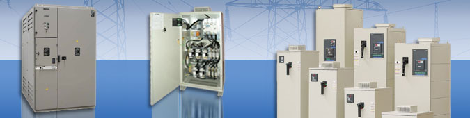
Для чего нужна установка компенсации реактивной мощности?
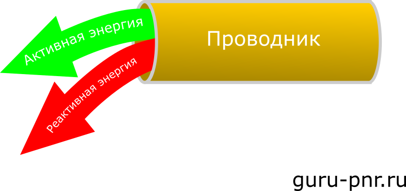
Как известно из курса электротехники, электрическая энергия бывает двух видов: активная и реактивная. Активная — это та энергия, которая потребляется (преобразуется) из одного вида в другой и выполняет какую-либо полезную работу. Например, крутит вал электродвигателя, нагревает нагревательный элемент, преобразуется в световой поток и освещает что-нибудь. Реактивная энергия — это энергия, которая циркулирует от источника к потребителю и назад. Она не потребляется, а возвращается назад в источник, чем оказывает паразитное воздействие на электрическую сеть.
Казалось бы, что плохого в реактивной энергии? Ну, носится она туда-сюда, что с неё взять? Однако, нужно понимать, что чем её больше, тем меньше активной энергии передается от источника к потребителю, потому что провод в зависимости от сечения имеет ограничения на передачу тока. Следовательно, выполняется меньше полезной работы, то есть коэффициент полезного действия питающей линии уменьшается. Пропускать по питающей линии больше энергии — нужно увеличивать сечение провода, а это дорого. Поэтому самый лучший вариант — избавиться от реактивной энергии совсем.
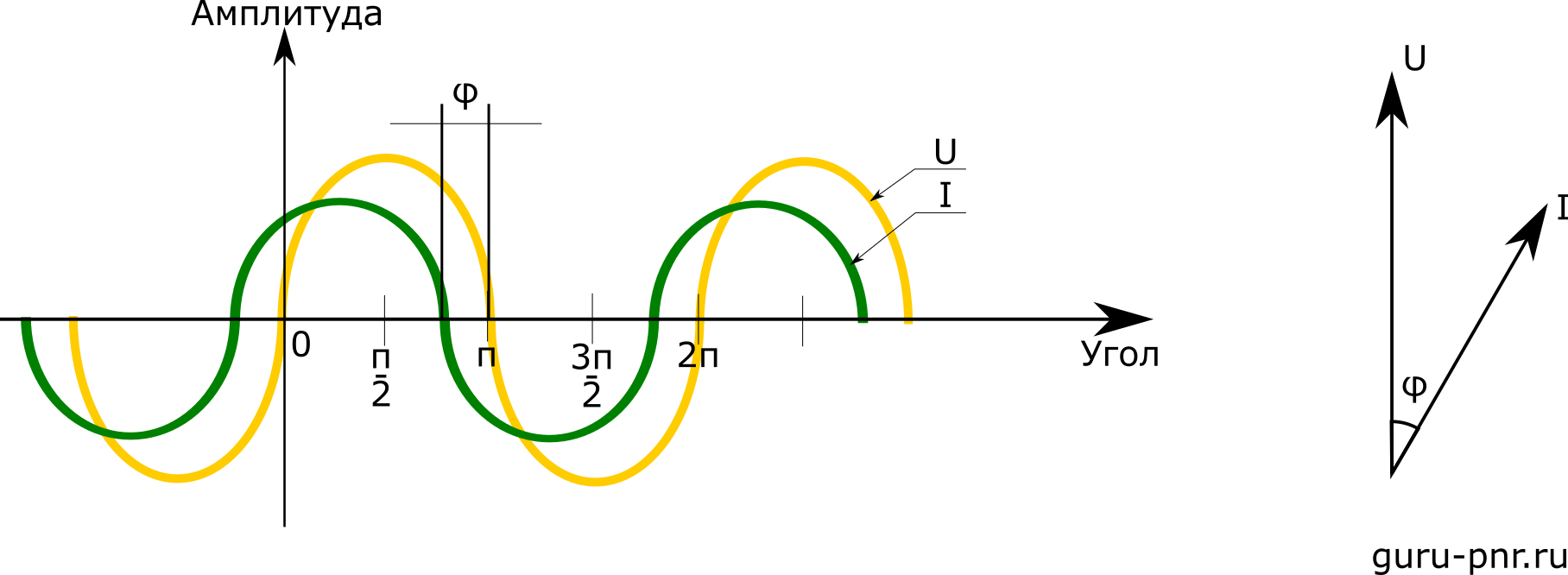
Есть несколько способов это сделать. Один из них — установка устройства компенсации реактивной мощности (УКРМ). Это самый простой и дешевый способ поднятия КПД питающей линии. Суть его заключается в том, что у потребителя устанавливаются батареи конденсаторов, которые являются накопителями электроэнергии. Как известно, потребители электроэнергии имеют активно-индуктивный характер, т. е. состоят из активных потребителей (например, нагреватели) и активно-индуктивных (обмотки трансформаторов, катушки реле, электродвигатели — провода в них тоже нагреваются). Так же известно, что при таком характере нагрузке ток отстает он напряжения на угол от 0 до 90 градусов. Проще говоря, когда напряжение на нагрузке уже достигло максимума (амплитудного значения), ток еще не успел этого сделать и достигнет максимума чуть позже, когда величина напряжения будет уменьшаться. Идеальным вариантом является ситуация, когда ток без опоздания от напряжения появляется на нагрузке и точь-в-точь повторяет форму напряжения. Это характерно для чисто активной нагрузки.
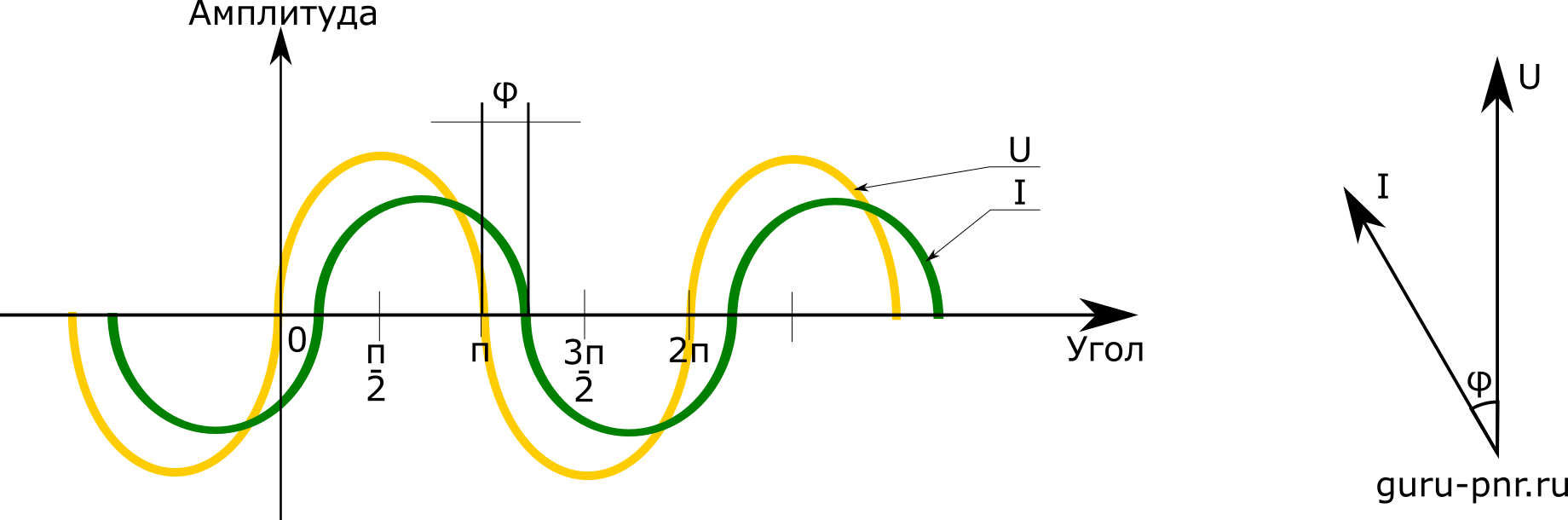
Если к индуктивности ток бежит неохотно, то к ёмкости он бежит вперед напряжения. Ток обожает ёмкость. Поэтом, чтобы «приманить» ток к нагрузке, и устанавливают конденсаторные батареи. К ним ток бежит охотнее, работает — не ленится, поэтому КПД линии повышается.
Это свойство и используют для того, чтобы скомпенсировать реактивную энергию. Сама конденсаторная установка — простейшее устройство, состоящее из конденсаторов, которые подключаются параллельно друг другу. Подключаются они могут все сразу — тогда конденсаторная установка является не регулируемой — или в определенной последовательности, в зависимости от набора емкостей. Каждый набор называют ступенью. Ступени предназначены для дробления общей емкости УКРМ и чем их больше, тем точнее УКРМ позволяет регулировать коэффициент мощности.
Если УКРМ регулируемая, то в её составе есть специальный контроллер, которому для поддержания нужного коэффициента мощности требуется информация о напряжении и токе нагрузки. Зная напряжение и ток, контроллер вычисляет рассогласование между ними (отставание или опережение тока от напряжения), а это и есть коэффициент мощности или COS φ. По величине рассогласование контроллер определяет сколько ступеней подключить или отключить, чтобы добиться заданной величины COS φ. Вот так вот всё просто и не затейливо.
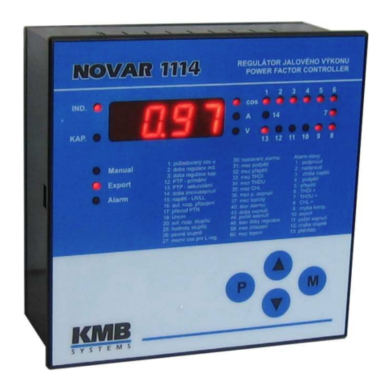
Правильная настройка регулятора
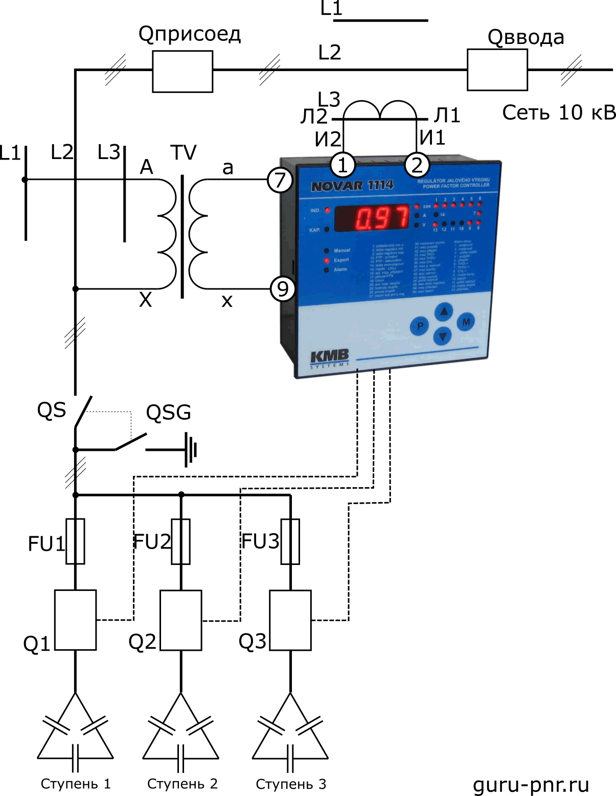
Чтобы регулятор правильно работал, он должен получать достоверные данные тока и напряжения. Поэтому его нужно правильно подключить. Нет ничего лучше для понимания теории, как применение её на практике. На практике оказался регулятор NOVAR 1214 — один из самых распространенных, поэтому на его примере и практике рассмотрим основные параметры настройки регулирования COS φ.
Требуемый COS φ: Это задание для поддержания нужного значения COS φ в сети.
Было задано значение: 0,9
Время регулирования при недокомпенсации: Когда COS φ меньше, чем требуемый ровно на такую величину, что его может скомпенсировать самая маленькая ступень конденсаторов, то выжидается это время, прежде чем ступень будет включена. Если рассогласование больше, чем смогла бы скомпенсировать самая маленькая ступень конденсаторов, то время сокращается по одному из двух законов — квадратично или линейно (параметр с буквой L). Это можно задать при настройке.
Если же рассогласование меньше, чем могла бы скомпенсировать самая маленькая ступень, то время увеличивается в два раза. Регулирование прекращается, когда рассогласование меньше, чем могла бы скомпенсировать 1/2 емкости самой маленькой ступени конденсаторов.
Оставлено заводское значение 3 мин.
Время регулирования при перекомпенсации: Когда COS φ больше, чем требуемый, это считается «перекомпенсацией» и алгоритм работы такой же, как и при «недокомпенсации», только здесь ступени не подключаются, а отключаются по истечении указанного времени.
Оставлено заводское значение 30 сек.
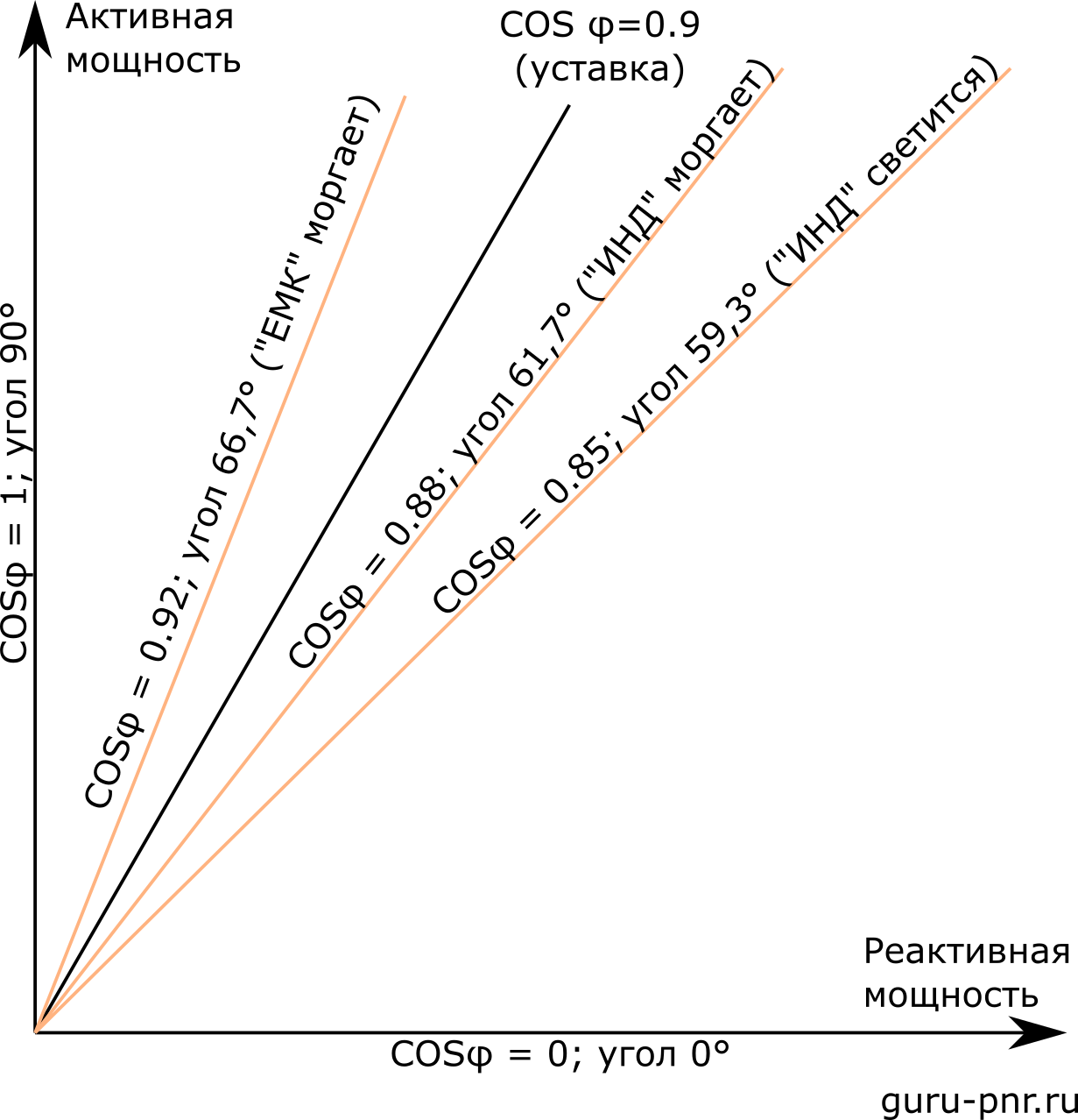
Ширина полосы регулирования при большой нагрузке: Если в системе электроснабжения периодически возникают большие переменные нагрузки, вызывающие некоторое отклонение COS φ на какое-то время, чтобы зря не включать/отключать дополнительные ступени, предусмотрен данный параметр. Он несколько расширяет полосу регулирования в зоне большой нагрузки на заданный диапазон:

Как видно из рисунка, в зонах «А» и «B» ширина зоны нечувствительности определяется емкостью наименьшей ступени. Зона «С» начинается там, где полоса нечувствительности начинает расходиться. Таким образом, чем больше нагрузка, тем больше отклонение от уставки и тем больше зона нечувствительности.
Установлено заводское значение 0,010
Номинальный первичный ток: Первичный ток измерительного трансформатора тока. Этот параметр нужен для правильной индикации мощностей, на что-то существенное он не влияет.
Для трансформатора тока 800/5 установлено значение 800
Номинальный вторичный ток: Выбирается из диапазона 5А или 1А. Этот параметр должен быть указан правильно, иначе расчет COS φ будет неверным.
Установлено значение 5 А
Время блокировки повторного включения: Время достаточное для разряда конденсаторов в одной ступени перед тем как она снова будет включена. Пока это время не истекло, данная ступень не включится даже в ручном режиме, поэтому при необходимости будут включаться другие ступени, у которых время повторного включения уже вышло.
Установлено 10 мин по указанию инструкции на установку
Тип измерительного напряжения: Для правильного расчета регулятора нужно знать, какое измерительное напряжение подведено — линейное (LL) или фазное (LN).
Установлено LL (линейное), так как измерительный трансформатор напряжения подключен между фазами «A» и «B» (L1-L2).
Способ присоединения тока и напряжения: Параметр сообщает регулятору, как подключены измерительные цепи тока и напряжения относительно друг друга. Для регулятора жестко принято, что трансформатор тока находится в фазе «А» и Л1 направлено к источнику, а Л2 — к потребителям. Выбирается только способ подключения напряжений. Для линейного подключения: L1-N; L2-N; L3-N; N-L1; N-L2; N-L3. Для линейного подключения: L1-L2; L2-L3; L3-L1; L2-L1; L3-L2; L1-L3. Вот здесь придется поколдовать, если подключение отличается от стандартного.
Схема подключения предложенная производителем установки подразумевает, что трансформатор тока будет находится в фазе «С», а как уже упоминалось, измерение напряжения производится в фазах «A» и «B»:
С такой схемой подключения нельзя выбрать значение параметра L1-L2, потому что это будет неверно. Давайте разберемся. Рассмотрим векторную диаграмму, которая должна образоваться при нашем способе подключения и диаграмму, которую будет ожидать регулятор при выборе параметра L2-L3:
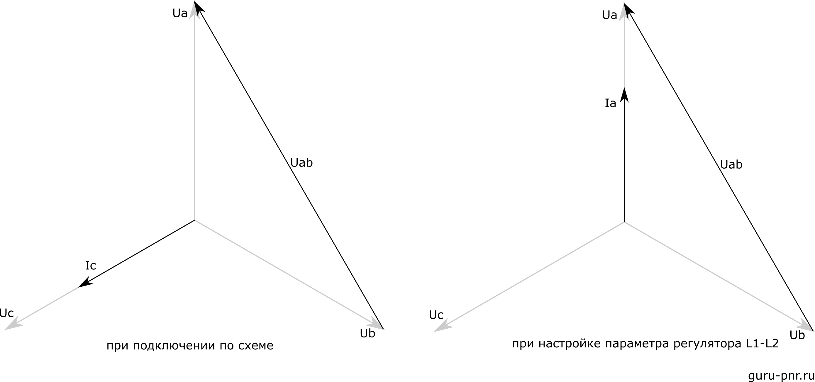
Как видно из рисунков, выставление параметров так, как это по факту даст неверную работу регулятора. Что же делать? Будем исходить из того, что для регулятора жестко принят тот факт, что ток меряется в фазе «А» (L1). Тогда развернем нашу векторную диаграмму так, чтобы ток фазы «С» совпал с током в фазе «А»:
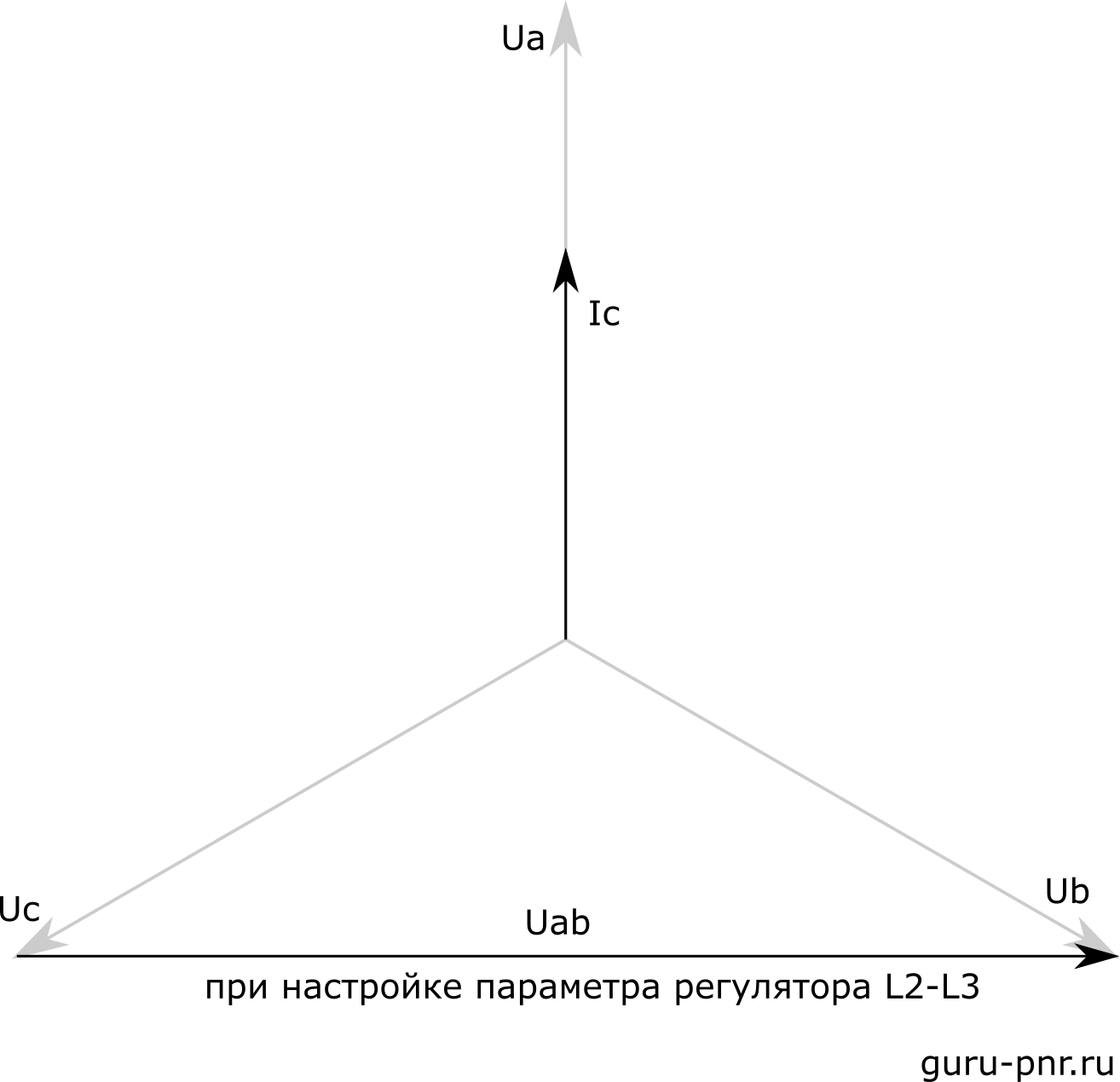
Теперь более чем очевидно, что напряжения нужно выбирать не L1-L2, а L2-L3.
Коэффициент измерительного трансформатора напряжения:
В нашем случае сеть имеет номинальное напряжение 10 кВ, а вторичка трансформатора — 100 В, следовательно, коэффициент равен 100
Номинальное напряжение компенсирующей системы:
Установлено 10, что соответствует напряжению 10 кВ
Программа коммутаций: Это комбинация ступеней, где для каждой ступени указано число, кратное мощности наименьшего конденсатора. Например, 1123 означает, что к первой и второй ступени присоединены конденсаторы с наименьшей емкостью; ко второй ступени — емкость батареи в два раза больше; третья ступень имеет емкость конденсаторов в три раза больше. Условия такие: к первой ступень должна быть подключена наименьшая емкость; емкости для ступеней больше, чем пятая считаются равным как у пятой.
Для нашей установки подойдет 1111, так как все конденсаторы имеют одинаковый номинал
Номинальная мощность наименьшего конденсатора: Задается в КВар дискретно
Установленные конденсаторы имеют мощность 450 кВар. Регулятор предложил 433 или 466. Был выбран 466 как ближайший.
Количество конденсаторов:
Установлено 2, выбираем 2.
Номинальная мощность отдельных ступеней: Указывается, какие конденсаторы в каких ступенях установлены
Так как ступени одинаковые, то указал для всех значение 466
Регулируемые/постоянные ступени: Указывается, какие ступени будут регулироваться (C или L), какие будут включены постоянно (1), какие будут отключены вовсе (0). Замечу, что регулируемые ступени могут быть как емкостные (С), так и дроссельные (L). Поэтому нужно указать соответствующую букву при выборе регулируемой ступени.
Так как в нашем случае используются только емкостные ступени, для них был установлен индекс «C».
Эти параметры основные и как правило их достаточно для того, чтобы настроить работу регулятора мощности.
Проверка работы регулятора
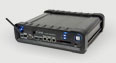
Теперь нужно проверить правильность настроек и алгоритма работы. Для этого нужен источник тока и напряжения с регулируемым углом между ними. Для таких целей вполне подойдет Ретом-21 или что-то аналогичное. Начнем с подключений:
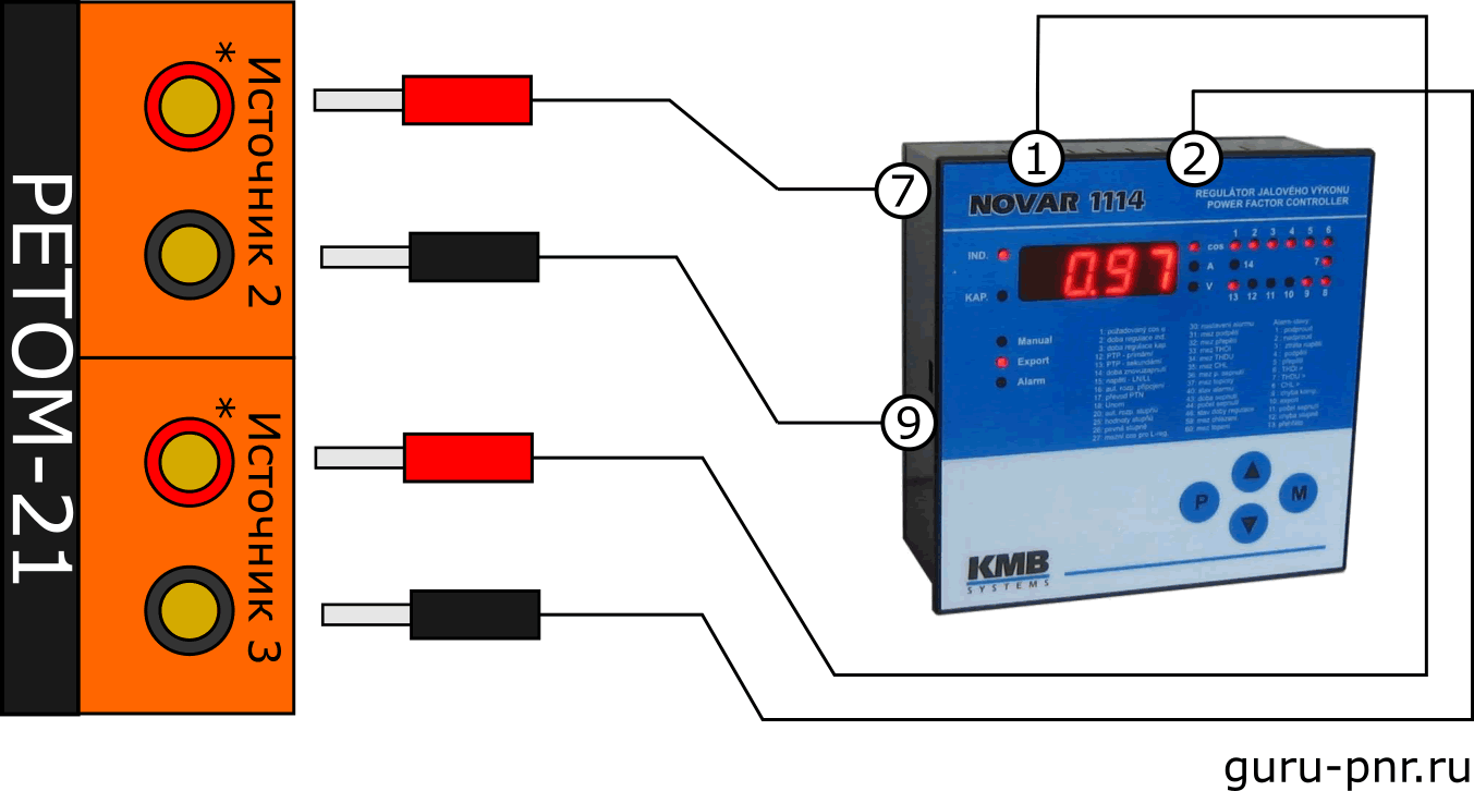
Задаем 100 В в измерительный канал напряжения и около 2 А в измерительный канал тока. Угол между напряжением и током должен быть +90°, так как для нашей схемы подключения ток опережает напряжение на 90°. Это состояние будет соответствовать COS φ = 1.
Проверка правильности подключения
Вращая фазорегулятор и наблюдая за показаниями на дисплее регулятора NOVAR 1214 убедиться:
- Максимальное значение активная мощность принимает при углах +90° и -90° (270°), а реактивная мощность стремиться к нулю;
- В этих же точках COS φ = 1;
- При +90° активная мощность имеет положительный знак, а при -90°(270°) — отрицательный, и загорается светодиод «Экспорт»;
- В точках 0° и 180° активная мощность — минимальна, реактивная мощность — максимальна;
- COS φ = 0;
- При 0° реактивная мощность — положительна (или с индексом «L»), а при 180° — отрицательна (или с индексом «С»). Такое обозначение знака, не характерное для электротехники, принято в регуляторе.
Если всё так, то проверяем работу алгоритма.
Проверка работы регулятора с действием на ступени
Проделаем следующие шаги:
- Устанавливаем значение напряжения 100 В, тока — 2 А;
- Выставляем по дисплею регулятора требуемый COS φ = 0.9;
- Медленно вращая фазорегулятор в сторону уменьшения косинуса (угол стремится к 0°) находим момент, когда начинает моргать светодиод «ИНДУКТИВНОСТЬ«. Фиксируем значение этого угла. Моргание светодиода говорит о том, что мы вышли из зоны, когда половина наименьшей ступени конденсатора могла бы скомпенсировать COS φ;
- Вращаем регулятор далее к уменьшению косинуса (угол стремится к 0°), находим момент, когда светодиод «ИНДУКТИВНОСТЬ» начинает светиться ровным светом. Засекаем угол и время. Через время, равное времени регулирования при недокомпенсации, должна сработать одна из ступеней, как правило — первая.
- Дожидаемся, когда включатся последовательно все ступени, каждая по истечении времени регулирования при недокомпенсации;
- Вращая фазорегулятор в сторону увеличения COS φ (угол стремится к 90°), достигаем момента, когда начинаем моргать светодиод «ЕМКОСТЬ«. Светодиод «ИНДУКТИВНОСТЬ» погаснет во время увеличения угла. Фиксируем угол и засекаем время. Ступени должны начать отключаться последовательно по истечении удвоенного времени регулирования при перекомпенсации.
- Увеличивает ток до 4 А;
- Выставляем по дисплею регулятора требуемый COS φ = 0.9;
- Медленно вращая фазорегулятор в сторону уменьшения косинуса (угол стремится к 0°) находим момент, когда начинает моргать светодиод «ИНДУКТИВНОСТЬ«. Значение этого угла должно быть меньше, чем в пункте 3.
- Вращаем регулятор далее к уменьшению косинуса (угол стремится к 0°), находим момент, когда светодиод «ИНДУКТИВНОСТЬ» начинает светиться ровным светом. Угол и время срабатывания должны быть меньше, чем в пункте 4.
- Дожидаемся, когда включатся последовательно все ступени;
- Вращая фазорегулятор в сторону увеличения COS φ (угол стремится к 90°), достигаем момента, когда начинаем моргать светодиод «ЕМКОСТЬ«. Угол должен быть меньше, а время — такое же как и в п. 6.
Ниже приведена диаграмма срабатывания регулятора в зависимости от угла между током и напряжением.
Предложенная далее проверка не является догмой. Вы можете сами определить достаточность мер для проверки, уменьшить их или увеличить. В любом случае, если Вы поделитесь своими мыслями и аргументами — это только улучшит нашу методику.