Содержание
- Нужна программа lasercut
- Нужна программа lasercut
- Нужна программа lasercut
- Нужна программа lasercut
- Thread: CO2 Laser with Leetro 6515 — Software problems
- CO2 Laser with Leetro 6515 — Software problems
- Leetro and Linkmotion
Нужна программа lasercut
Нужна программа lasercut
Сообщение kronk » 26 мар 2010 09:56
Сообщение sinner » 26 мар 2010 10:44
lasercut подойдет любой, будет только перемещение портала. Нужно знать версию прошивки платы, заменить библиотеки dll.
Сообщение Kirill » 06 апр 2010 13:16
Сообщение Олег Олегыч » 07 апр 2010 08:01
В архиве проги от китайца Baisheng, подойдут, видимо, под любой станок на базе DSP.
Плагин под Corel и Cad, Laser 1.6, некоторое количество мануалов по прогам и станку на ломаном английском. USB драйвер, драйвер для Dog ключа(отказался устанавливаться).
Прога под Corel для лазера HALK на русском языке — аналог проги для Baisheng. Не требует ключа. На нашем китайце работает без проблем, разве что нет кнопок Curve Precision и Password Set. Но первая не используется, а вторая все равно не работает.
P.S: USB ключ MicroDog, кстати, так и не смог установить. Дрова MicroDog driver 4.0.16.2 не помогли, возможно по вине Win 7, на других ОС не пробовал. Так что «станковый» комп работает на LPT ключе, а на ноут через HALKовскую прогу.
Сообщение ShNMikhail » 03 сен 2010 07:10
Сообщение sinner » 03 сен 2010 09:33
Сообщение ShNMikhail » 03 сен 2010 10:40
Сообщение sinner » 03 сен 2010 10:43
Сообщение ShNMikhail » 03 сен 2010 13:26
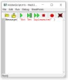
Нашел laserCut4.0. Драйвер на ключ установился, программа запускается, но перед открытием главного окна ругается: Open motion — Card error!
Что может быть не так?
И еще обнаружил последствия вандализма: на панеле гравера выключатель с ключом слева, а справа. пусто! Вырвали с корнями.
Осталось только колодка с клемами (изнутри посмотрел). Мои догадки, там кнопка экстренного отключения? (Я лох в этих делах) Там две пары клем каждая пара красный и черный провод. Они должны быть нормально замкнутыми или разомкнутыми? Пробовал всяко, но еще и в том проблема что с кнопок на панеле не перемещается головка, и все кнопки не работают, миллиамперметр молчит.
Кто сталкивался с VISTA L900, позади гравера провода питания 220В два штуки. один подключен в стабилизатор питания,- разъем стандартный компьютерный, а второй не подключен,- но он компьютерный и типа как в бесперебойник. Бляха! не знаю как он называется. Куды его девать (подключать).
Зеленые клавиши включения на правой стенке гравера обе загораются, всключаются, гудит транс внутри (высокое напр. я понимаю).
ПОМОГИТЕ НУБУ, пожалуйста.
Добавлено спустя 10 минут 57 секунд:
Проводку посмотрел, клемы на правой кнопки точно эмергенси стап. Должны быть замкнуты попарно. но с панельки по прежнему не чухается (верх-низ-лево-право, лазер тест. ).
Источник
Нужна программа lasercut
Нужна программа lasercut
Сообщение kronk » 26 мар 2010 09:56
Сообщение sinner » 26 мар 2010 10:44
lasercut подойдет любой, будет только перемещение портала. Нужно знать версию прошивки платы, заменить библиотеки dll.
Сообщение Kirill » 06 апр 2010 13:16
Сообщение Олег Олегыч » 07 апр 2010 08:01
В архиве проги от китайца Baisheng, подойдут, видимо, под любой станок на базе DSP.
Плагин под Corel и Cad, Laser 1.6, некоторое количество мануалов по прогам и станку на ломаном английском. USB драйвер, драйвер для Dog ключа(отказался устанавливаться).
Прога под Corel для лазера HALK на русском языке — аналог проги для Baisheng. Не требует ключа. На нашем китайце работает без проблем, разве что нет кнопок Curve Precision и Password Set. Но первая не используется, а вторая все равно не работает.
P.S: USB ключ MicroDog, кстати, так и не смог установить. Дрова MicroDog driver 4.0.16.2 не помогли, возможно по вине Win 7, на других ОС не пробовал. Так что «станковый» комп работает на LPT ключе, а на ноут через HALKовскую прогу.
Сообщение ShNMikhail » 03 сен 2010 07:10
Сообщение sinner » 03 сен 2010 09:33
Сообщение ShNMikhail » 03 сен 2010 10:40
Сообщение sinner » 03 сен 2010 10:43
Сообщение ShNMikhail » 03 сен 2010 13:26
Нашел laserCut4.0. Драйвер на ключ установился, программа запускается, но перед открытием главного окна ругается: Open motion — Card error!
Что может быть не так?
И еще обнаружил последствия вандализма: на панеле гравера выключатель с ключом слева, а справа. пусто! Вырвали с корнями.
Осталось только колодка с клемами (изнутри посмотрел). Мои догадки, там кнопка экстренного отключения? (Я лох в этих делах) Там две пары клем каждая пара красный и черный провод. Они должны быть нормально замкнутыми или разомкнутыми? Пробовал всяко, но еще и в том проблема что с кнопок на панеле не перемещается головка, и все кнопки не работают, миллиамперметр молчит.
Кто сталкивался с VISTA L900, позади гравера провода питания 220В два штуки. один подключен в стабилизатор питания,- разъем стандартный компьютерный, а второй не подключен,- но он компьютерный и типа как в бесперебойник. Бляха! не знаю как он называется. Куды его девать (подключать).
Зеленые клавиши включения на правой стенке гравера обе загораются, всключаются, гудит транс внутри (высокое напр. я понимаю).
ПОМОГИТЕ НУБУ, пожалуйста.
Добавлено спустя 10 минут 57 секунд:
Проводку посмотрел, клемы на правой кнопки точно эмергенси стап. Должны быть замкнуты попарно. но с панельки по прежнему не чухается (верх-низ-лево-право, лазер тест. ).
Источник
Thread: CO2 Laser with Leetro 6515 — Software problems
Thread Tools
Search Thread
Display
CO2 Laser with Leetro 6515 — Software problems
Software Dll does not match Firmware.
I posted this earlier and could be in the wrong place on this forum:
http://www.cnczone.com/forums/showthread.php?p=784346
So copy / paste here with some editing & corrections:
We purchased a CO2 100 watt 1.3m x 1.3m laser from Jinan Maohong Industry and Trade Co., Ltd., www.jxsycnc.com. This 1313 size is not shown on their website and they do seem to have many other sizes not listed as well. As with others in statements here, the machine hardware is okay. And again with others getting it set up in concerns of the software has NOT been easy.
It has: Leetro MPC6515 controller. Cooler is CW3000. Software LaserCut 5.3
After many loops we have been able to get the laser to test and then thus focus the lenses. Problem we have now is again with software and matching to the controller firmware. Using the file Mpc05Ver+M05.exe the report is:
Software dll version is: 4.1.2.2
Firmware version is: 4.2.1.0
Has anyone faced this problem & have answers to fix this Dll version problem?
I have tried searching up and down in Leetro and other sites but cannot find the correct dll file.
This site does have many files for Leetro and Laser software:
www.scottware.net
Makes it further a huge CSI being the name of files is not clear as to what version it is. The download files on the Leetro site is only in the Chinese site and are not on the English version site. I did use google to translate — but that only helps for the some of the pages and not for finding the correct files. The supplier does answer but replies do not get the problem solved.
Latest advice fix they sent shows to re-install LaserCut 5.3 and copy all the dll files — but this still does not work. BTW the email answer showing the LaserCut menu files are all labeled in Chinese. Ouch !!
Getting these lasers up and running in relation to the software — with what I read here — is a very widespread problem. And one of bit by bit getting it figured out as of bad manuals. I notice in other manuals (I downloaded many from other mfg’s) that there are some parts that have further info but then as well not having info that is in others. So it seems a person has to look at many manuals and conglomerate info. Further it seems most problems are common across the many manufacturers. So it seems a generic well laid out but simple step by step manual would be of great help to many to overcome the lacking in all the currently badly written manuals. I would give it a shot but for sure would it would need a group force to ensure it hits and covers all the main points and kept as KISS as possible.
Anyway a fairly long post and hope somebody can answer the version problem. And onwards of how to get clarity for others with making a KISS manual.
What Scottware does is provides the PC with software already set up for the machine. I reckon this is the way to go. This whole bag of problems is (mostly) avoided being it is loaded and tested to function as a complete package. So — my suggestion to any newbies — — get the PC with the machine. Whatever extra money spent will be more than worth it.
Cheers, Dave Crocketman
Really this question better ask to manufacturer.
I have as said already contacted the mfg but answers back are not giving me the correct info and with any explanation of dll files — and of course simply just sending me the correct dll file. LaserCut 5.3 has many dll files for the versions and I am guessing thus backwards compatible — but problem here is not backward — rather we need a newer dll as the firmware is new.
Anyhow — I notice as well:
Has anyone tried this ??
I would buy it being I know it really works well with the Leetro 6515, and no more banging a tamborine while dancing magic rings around the laser and hoping it works after dozens more emails with the mfg.
I have experience that you can get working combination of firmware and dll only from manufacturer
My suggestion is offer small amount of money for fast resolving of problem to service engineer, and you will be surprised how quickly everything will be done
 My suggestion is offer small amount of money for fast resolving of problem to service engineer, and you will be surprised how quickly everything will be done
Do some searching here for a contributor called «mononeuron» or something close to that. I seem to recall he had used the Link Motion or was waiting on the new version. That was at least a year back, maybe more so my memory is a bit hazy.
Has anyone tried this ??
Yup. I bought Linkmotion for my laser which uses the Leetro 6515. After many emails to and fro, :argue: finally got it working.
It installs as a print driver so you can ‘print’ from any application, e.g. Corel Draw.
There is at least one ‘gotcha’ — it will only do raster OR vector, so for some jobs you need to send two files to the laser to complete the job — unlike LaserCut which can do both in one file.
I was promised a free upgrade when this capability was (soon to be) added to Linkmotion — and heard nothing since (Jan ’09)(chair)
These days, I hardly ever use it — it’s just too much hassle having to go through hoops to complete a job.:tired:

Leetro and Linkmotion
I apologize for the long reply in advance but I have a lot to talk about.
I bought my «Upgrade» last year about Nov-Dec and had some issues with the install and setting up the table.
The install is a bit different to the software only Linkmotion setup and you need to find the steps per «millimeter» for each axis and the size of each axis in pulses ( i.e 76,000 pulses to move 32 inches etc.) then type in the software the actual size of the table in inches. It’s a very convoluted way to do things and it would be so much easier if they just wrote a small program to move the axis a certain amount and then measure the travel and input the correction. Just like the Mach3 software has. Dead simple.
But no, they don’t do that, so you need to count how many pulses for 1 complete turn of the motor and measure how far it travels then divide that by the number of pulses etc, etc. very inelegant.
You need to set up the «INI» file to your specific machine and it is covered relatively well in the documentation then click on «initialize» in the Laser tab of the software. This is probably the most important part of the set up.
Some of the terminology is a bit confusing too as it may say «laser on» in the docs but it really means «laser diode (red pointer) on». I misread this to be the 30 watt laser on connector and it took me a while to find out it wasn’t.
I haven’t had any problems with the Vector cutting at all and it runs pretty sweet. but that wasn’t why I bought the upgrade as vector cutting was always good with Linkmotion.
I bought it for the increased speed for Bitmap/Raster engraving and I must say the improvements are really outstanding. If I run it at the fastest speed I am game to run it at (12 ips ) I shake the table to pieces. I limit it to 8 ips for the tables sake 🙂
I wasn’t able to process a file over 9″ in size and after NUMEROUS emails to tech support I found out that I have to create a transparent background for the file as Linkmotion doesn’t do «white» very well. I have asked them heaps of times how to do this but they still haven’t told me how. Must be a trade secret and, also, it isn’t in any of the CorelDraw X4 help files either.
I have 4 Gig of RAM so memory isn’t a problem but I still get a VB script error if I go over 9″ in size.
Solustan sent me a converted bitmap file (one of mine) and I was able to process it up to 16″ and after that the program would crash again.
Email from Solustan was non existent over the Xmas period when I really needed help from them due to a back log of jobs for Xmas presents and I ended up canceling all jobs for the laser. about $1500 worth at that time.
My emails continued for the next few months with no reply until in around April they finally mailed me and said they weren’t helping me because I hadn’t set up my INI file properly and couldn’t help until I had that sorted out. Previously I hadn’t been able to get the red pointer to work or the air assist and they said they were in contact with the Leetro tech support and would get back to me. I have those working now and I had them wired incorrectly. Stupid me or poorly written manual. (Probably the former)
I went back to the laser and painstakingly set up all the settings again. A couple were out but it wasn’t by much and was only on the size of the table. Something like 76000 instead of 69942. This really doesn’t make much difference unless you use all of the available space on the table for 1 job.
Last month they sent me an upgrade with «Many» improvements but none that would make me give up my right hand for.
At this stage I still can’t produce an engraving over 9″ unless I find out how to erase the background to transparency . Any one know how to do this.
Please let me know.
Last time I used my rotary attachment I processed a raster file and sent it to the Leetro (printed). Then I pressed start and the laser head wobbled about 2mm wide and finished the 2.75 inch wide job in about 1/4 inch (squashed up together) I moved to another spot on the job and pressed start again and it engraved about 2.5 inches wide. Close to the 2.75 I had drawn. I moved yet again to another spot and pressed print again and it engraved about 3 inches wide. All this without reprocessing the job again. There is a fault in there somewhere that I have not been able to track down and Solustan say it is My INI problem. I have sent this INI to them numerous times with no feedback on what is wrong.
If I set my engraving speed to under 3 ips the laser head oscillates about 1/16″ wide all the way to the bottom of the job then returns to the home (0,0) position. Anything over 3 ips is ok. I need to engrave mirrors at 2.8 ips for them to turn out good so I have to set my engrave speed to 6 ips and set the Leetro controller to 50% speed for it to work. Inelegant solution but it does work.
There is no readout of the location of where the laser head is unlike the software only solution and I find this very annoying. If I engrave something and then want to place a name or something 1.2 inches away I have to set it with a rule. A minor bugbear but one I really liked with the old system.
My setup is nothing fancy and I only have a computer connected to the Leetro and then to the Gecko drives.
Am I happy with the system. Simple, NO!
Am I happy with the support. No! They used to be REALLY good but alas, now this isn’t so for me. I think I have become a pain to them.
Источник

![]()
-
05-09-2010, 05:22 PM
#1
Registered
- Join Date
- May 2010
- Posts
- 0
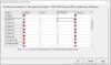
Open motion card error
I reinstaled mine system and instaled all of the software again.I use LaserCut 5.1 and when i pluged card again and instaled all of the drivers again and tryed to enter lasercut software it errors : Open motion card error.Whats the problem?Machine woked before reinstaling windows greatly.
Sorry if i missed a part of forum for asking question like this.
Sincearly
-
09-11-2010, 01:32 AM
#2
Junior Member
- Join Date
- Sep 2010
- Posts
- 15
Do you solved the problem? I have the same error and I don’t know what to do

Quick Navigation
Controller Cards
Top
- Site Areas
- Settings
- Private Messages
- Subscriptions
- Who’s Online
- Search Forums
- Forums Home
- Forums
- IndustryArena Site Support
- Questions or Problems
- Events, Product Announcements Etc
- News Announcements
- Trade Shows / Webinars / Other Events
- Cabin Fever Expo
- FABTECH
- IMTS
- Polls
- Environmental / Alternate Energy
- Videos
- Want To Buy…Need help!
- USED MACHINES
- For Sale Only
- Community Club House
- Mentors & Apprentice Locator
- Teachers and Students Hangout
- Education — Forum for Technicians and Engineers
- Employment Opportunity / RFQ (Request for Quote).
- Manufacture Company Listing
- Employment Opportunity
- RFQ (Request for Quote)
- RFQ Feedback
- Australia RFQ’s
- CANADA RFQ’s
- UK RFQ’s
- USA RFQ’s
- Machinery Manual, Brochure / Photo Archives
- Machinery Manuals / Brochures
- Member / Shop Photos
- CAM Software
- Uncategorised CAM Discussion
- Autodesk CAM
- Autodesk Post Processors
- ArtCam Pro
- Alphacam
- BobCad-Cam
- BobCAM for SolidWorks™
- BobCad Post Processors
- Tutorials
- CAM System — Compare
- CamWorks
- CamBam
- CutLeader
- Dolphin CAD/CAM
- EdgeCam
- Esprit
- EZ-CAM Solutions
- EnRoute
- FeatureCAM CAD/CAM
- GibbsCAM
- GRZ Software- MeshCAM
- Hypermill
- Mastercam
- Post Processors for MC
- MadCAM
- OneCNC
- Postprocessor for CAM
- PTC Pro/Manufacture
- PowerMILL
- Rhinocam
- SheetCam
- Post Processor Files
- Surfcam
- SolidCAM for SolidWorks and SolidCAM for Inventor
- SprutCAM
- UG NX
- Vectric
- Aspire
- Cut2D / Cut3D
- PhotoVCarve and VCarve Pro
- Post Processors
- Visual Mill
- Work-NC
- ZW3D CAM
- CAD Software
- Uncategorised CAD Discussion
- Alibre Design
- Autodesk
- Cadkey / KeyCreator
- Logic Trace CNC/DXF
- Rhino 3D
- Solidworks
- ViaCad / Shark
- Mechanical Engineering
- Epoxy Granite
- Linear and Rotary Motion
- Mechanical Calculations/Engineering Design
- T-Slot CNC building
- WoodWorking
- General WoodWorking
- WoodWorking Machines
- Uncategorised WoodWorking Machines
- CNC Machining Centers
- Commercial CNC Wood Routers
- Biesse
- Blue Elephant CNC
- Camaster
- Chinese Machines
- DynaCNC
- Excitech routers
- Gerber
- Gorilla CNC Machines
- K2CNC
- Larken
- LIMAC CNC Router
- Omni CNC
- Multicam Machines
- Rockcliff Machine
- Roctech CNC Routers
- Shopsabre
- Techno CNC
- XYZ Gantry Routers
- DIY CNC Router Table Machines
- FAQ of DIY CNC Machine Building
- Avid CNC
- CNC Wood Router Project Log
- FineLine Automation
- Joes CNC Model 2006
- Momus Design CNC plans
- Open Source CNC Machine Designs
- Zen Toolworks
- Wood Lathes / Mills
- MetalWorking
- General MetalWork Discussion
- Bending, Forging, Extrusion…
- Casting Metals
- Diemaking / Diecutting
- Mass finishing equipment/media/strategies
- Moldmaking
- Welding Brazing Soldering Sealing
- 80/20 TSLOTS / Other Aluminum Framing Systems
- MetalWorking Machines
- Uncategorised MetalWorking Machines
- Vertical Mill, Lathe Project Log
- Bending- and Punching Machines
- Drilling- and Milling Machines
- Auto Tool Changer
- Benchtop Machines
- X3/SX3/G0619/G0463
- RF-45 Clone Mill
- Taig Mills / Lathes
- Mini Lathe
- Turning Machines
- Bridgeport Machines
- Bridgeport / Romi Lathes
- Bridgeport / Hardinge Mills
- Cincinnati CNC
- CNC Swiss Screw Machines
- CITIZEN Machines
- Colchester Tornado lathes
- CNC «do-it-yourself»
- CNC Machining Centres
- Daewoo/Doosan
- Deckel, Maho, Aciera, Abene Mills
- Dyna Mechtronics
- EMCO CNC Machines
- EMCO Lathe
- EMCO Mills
- Fadal
- Haas Machines
- Haas Lathes
- Haas Mills
- Haas Visual Quick Code
- Hardinge Lathes
- Harrison Alpha
- Hitachi Seikis
- HURCO
- Hyundai Kia
- Kitamura
- Knee Vertical Mills
- LittleMachineShop
- Mikinimech
- Milltronics
- Mori Seiki Machines
- Mori Seiki lathes
- Mori Seiki Mills
- Novakon
- OKK
- Okuma
- Sharp CNC
- Shopmaster/Shoptask
- Smithy
- South Bend Machinery
- Swiss Lathes
- Syil Products
- Tormach Personal CNC Mill
- Tormach Slant Lathe
- Tormach PathPilot™
- Toyoda
- Tree
- Uncategorised MetalWorking Machines
- General Manufacturing Processes
- Milling
- Turning
- Drilling
- Grinding
- Chucking and Measuring
- Other Manufacturing Processes
- Safety Zone
- CNC Plasma, EDM / Waterjet Machines
- General Waterjet
- General EDM Discussion
- General CNC Plasma / Oxy Fuel Cutting Machines
- Plasma, EDM / Other similar machine Project Log
- DynaTorch
- DynaCNC
- PlasmaCam
- Hypertherm Plasma
- Torchmate
- Laser Engraving and Cutting Machines
- Commercial Laser
- AEON Laser
- BODOR Laser
- BOSS Laser
- G.Weike Laser
- Hurricane Laser
- LOGILASE Laser
- Redsail Laser
- Thunder Laser
- General Laser Engraving / Cutting Machine Discussion
- General Fiber Laser Cutting
- Laser Control Software
- LaserCut
- LaserGRAV
- Laser Hardware
- Laser CO2 Tubes, Diodes, RF and Power Supplies
- Laser Optics
- Laser Cooling
- Commercial Laser
- Power-to-X
- Power-to-X
- Other Machines
- General Other Machine Discussion
- CNC Wire Foam Cutter Machines
- Digitizing and Laser Digitizing
- Engraving Machines
- Machine Created Art
- Printing, Scanners, Vinyl cutting and Plotters
- PCB milling
- Commercial Products / Manufacturers Support Forums
- Automation Technology Products
- Bulltear Industries Support Forum
- Charter Oak Automation Support Forum
- CNC4PC
- General Maintenance
- SERVICE FOR CNC-MACHINES
- Maintenance DIY Discussion
- BallScrew Repair
- CNC Electronics
- General CNC Machine Related Electronics
- Dmm Technology
- DeskCNC Controller Board
- Gecko Drives
- G-REX
- Hobbycnc (Products)
- Phase Converters
- Leadshine
- PIC Programing / Design
- Rutex Products
- Servo Drives
- Servo Motors / Drives
- SmoothStepper Motion Control
- Spindles / VFD
- Stepper Motors / Drives
- UHU Servo Controllers
- Viper Servo drives
- Xylotex
- Machine Controllers Software and Solutions
- General CNC (Mill / Lathe) Control Software (NC)
- Bosch Rexroth
- Centroid CNC Control Products
- Controller Cards
- CamSoft Products
- Controller & Computer Solutions
- Dynomotion/Kflop/Kanalog
- Dynapath
- EdingCNC
- CNC-EDITOR
- CS-Lab CNC Products
- Deckel / Dialog
- LinuxCNC (formerly EMC2)
- FlashCut CNC
- Mori Seiki Software
- Fagor Automation
- Fanuc
- Mazak, Mitsubishi, Mazatrol
- G-Code Programing
- Parametric Programing
- Mach Software (ArtSoft software)
- Mach Wizards, Macros, & Addons
- Machines running Mach Software
- Mach Lathe
- Mach Mill
- Mach Plasma / Laser
- Mach 4
- Screen Layouts, Post Processors & Misc
- Fidia
- Mitsubishi controls
- DNC Problems and Solutions
- NCPlot G-Code editor / backplotter
- UCCNC Control Software
- PlanetCNC
- SIEMENS Sinumerik CNC controls
- SIEMENS -> SYSTEMFORUM
- SIEMENS -> GENERAL
- SIEMENS > Sinumerik 802D/840D/810D/828D
- SIEMENS > Sinumerik 810M/810T
- SIEMENS > Sinumerik 840C
- SIEMENS > ShopMill
- SIEMENS > ShopTurn
- SIEMENS > SinuTrain
- HEIDENHAIN
- HEIDENHAIN -> GENERIC
- HEIDENHAIN -> TNC
- HEIDENHAIN -> MillPlus
- HEIDENHAIN -> ManualPlus / CNC Pilot
- HEIDENHAIN -> iTNC530 PC-SOFTWARE
- Hurco
- Index and Traub
- Visual Basic
- Okuma
- WinCnc
- Philips
- OpenSource CNC Design Center
- Opensource Forum Rules
- Arduino
- Coding
- OpenSource Software
- Open Source Controller Boards
- Engraving / Art Design Software
- General Jewelry Design Software
- SignMaking
- General Signmaking Topics
- Tips / Tricks
- Portfolio Board
- Additive Manufacturing / 3D Printers and 3D Scanners
- General 3D Printer / 3D Scanner Discussion
- 3D Printing / Scanning Software and Hardware
- Electronics
- Material Technology
- General Material Machining Solutions
- Composites, Exotic Metals etc
- Glass, Plastic and Stone
- Vacuum forming, Thermoforming etc
- Metallurgy
- Plastic injection
- Hard / High Speed Machining
- Computer Technology
- Desktops / Laptops
- Operating System software
- USB, RS232, PARALLEL etc
- Computers / Networking
- Tools / Tooling Technology
- Calibration / Measurement
- CNC Tooling
- Metalworking- / Woodworking Tooling / Manual Machining
- Work Fixtures / Hold-Down Solutions
- Toolgrinding / Toolgrinding Machines
- Hobby Projects
- Hobby Discussion
- I.C. Engines
- Wooden Clocks
- Gunsmithing
- Musical Instrument Design and Construction
- RC Robotics and Autonomous Robots
Similar Threads
-
Replies: 15
Last Post: 04-02-2012, 08:38 PM
-
Replies: 4
Last Post: 03-14-2008, 07:03 AM
-
Replies: 3
Last Post: 03-06-2005, 10:41 PM
Posting Permissions

- You may not post new threads
- You may not post replies
- You may not post attachments
- You may not edit your posts
- BB code is On
- Smilies are On
- [IMG] code is On
- [VIDEO] code is On
- HTML code is Off
Forum Rules
All times are GMT +1. The time now is 11:37 PM.
Powered by vBulletin® Version 4.2.5
Copyright © 2023 vBulletin Solutions Inc. All rights reserved.

Topic: RnR Mtion Card Not Found (Read 10146 times)
0 Members and 1 Guest are viewing this topic.
I have been using a Chinese 60/40 cnc with Mach3 for a year without issue until today. On completion of a job, the software bombed and on restarting gave me the following status message after clicking the RESET button, ‘RnR Motion Card Not Found’. Any ideas on what might have happened?

Logged
Hi,
it sounds like Mach can’t establish communication with the motion card.
The fact that Mach is looking for it confirms that the RnR card is correctly set as the nominated motion controller.
Further I think if Mach can’t find the .dll file which is the plugin for the card it comes up with a different error,
which tends to suggest that the .dll file is found.
One possibility is that the USB connection or its driver is faulty. I believe the USB and drivers are supplied by Windows
not Mach or the RnR plugin. Another possibility is that the RnR plugin is corrupt. Remember that Mach actually
communicates with the plugin and then the plugin communicates to the Windows USB driver.
Do you have a backup copy of the plugin (.dll ) file? If so try substituting it for the potentially corrupt version in
the Mach3/Plugins folder.
Craig
Logged
My wife left with my best friend…
and I miss him!
Hi Craig,
Thank you so much for your swift response. I have reinstalled the .dll plugin with no luck. I have also checked the cable and I assume the USB driver is fine as I can still attach drives, keyboards etc.
Could it be a problem with my CNC controller board? I was experiencing some static on my final job and wonder whether the contoller board may have been damaged.
Thanks for taking time to help!
Mike
Logged
Hi,
Could it be a problem with my CNC controller board? I was experiencing some static on my final job and wonder whether the contoller board may have been damaged.
Yes, it is possible, even likely. Those boards are cheap and low quality. Very little is known about them.
Craig
Logged
My wife left with my best friend…
and I miss him!
You are right Craig, very little indeed.
I’m thinking that I should try using the Gecko system, turning a mishap into a chance to improve my situation. Any suggestions on alternative directions?
Mike
Logged
Hi,
a Gecko G540 is a parallel port input device whereas your existing board is a USB input external motion controller,
different animal. Unless your PC is Windows 7 32 bit or earlier then a parallel port is not an option.
If you want an external motion controller to replace what you have then I would recommend US or European made.
Just about all of them are Ethernet connected these days as they are very much preferred over USB in CNC use.
The Ethernet SmoothStepper by Warp9 or a UC300 by CNCDrive are worthy boards.
There are plenty of Chinese boards, many of them USB connected, but they don’t work at all well, if they work at all
and you will get no help from them if you encounter trouble. Don’t go there.
Craig
Logged
My wife left with my best friend…
and I miss him!
Thank you Craig, I’ll take a look.
Logged
Can you pull the cover off your electronics box (make sure to have mains power of the electronics box unplugged but plug USB cable to another USB port of your computer.
USB ports on computers have individual fuses. But another USB port of the computer may still work.
If no LED of the board is lid, you need to buy another motion card.
Logged
«the gift of God is eternal life through Jesus Christ our Lord»
Thanks for the advise. No issues with the USB inputs. I have ordered a replacement board which should arrive in a week. Fingers crossed.
Logged
A huge thank you to both of you for your wonderful help. I have just swapped out the motion card and the system is up and running. I seriously appreciate you taking time out of your day to help others.
All the best,
Mike
Logged
РЕШЕНИЕ ПРОБЛЕМ С MACH3 И СТАНКОМ ЧПУ ПОД КЛЮЧ ОТ 8000 руб.
ВМЕСТЕ С ЛИЦЕНЗИЕЙ Mach3 ЗА 11 950 руб.
БЕЗ СМЕЩЕНИЙ ПО ОСЯМ, ЗАВИСАНИЙ, СБОЕВ И ОШИБОК
СПЕЦИАЛИСТ С ОПЫТОМ 15 ЛЕТ
СОПРОВОЖДЕНИЕ ДО РЕЗУЛЬТАТА
ТЕХ ПОДДЕРЖКА И ГАРАНТИЯ 5 ЛЕТ НА СТАБИЛЬНУЮ РАБОТУ СТАНКА
Вы получите стабильно работающий ЧПУ станок
за 1-2 дня*
Дистанционная настройка по России, СНГ и
другим странам с русскоговорящими клиентами
Для фрезерных, плазменных и токарных станков ЧПУ. Станков для алмазной проточки дисков.
Я РЕШАЮ СЛЕДУЮЩИЕ ПРОБЛЕМЫ:
- Смещение по осям X или Y.
- Смещение по глубине (оси Z).
- Mach3 и компьютер зависают. Mach3 не сохраняет настройки или сбросила все настройки. Требуется перезагрузка Mach3 или переустановка Windows. Mach3 не кооректно читает код.
- Mach3 глючит. «Глючит пиратская или китайская версия».
- Выдает ошибку «Error Triggered. Art Code 3336, 9991, 8877», «Device Error Triggered», «Device Buffer Error» и др.
- Станок останавливается, дергается. Не возвращается точно в ноль.
- Станок вырезает изделие меньше/больше по масштабу
- Mach3 не видит станок, контроллер
- Пропуск шагов.
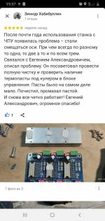
ФОТО НЕ КОРРЕКТНОЙ РАБОТЫ СТАНКА ОТ КЛИЕНТОВ:
СМОТРИТЕ ВИДЕО:
ЧТО ВЫ ПОЛУЧАЕТЕ ПОСЛЕ НАСТРОЙКИ:
Стабильная и надежная работа станка и Mach3:
·
Без ухода фрезы в сторону или глубину
·
Без остановок, зависаний, сбоев и ошибок в Mach3
·
Точный возврат в ноль по всем осям·
Mach3 не будет «глючить»
Полностью русифицированный интерфейс Mach3
Официальную лицензию Mach3
Дополнительно настрою:
·
Вкл/выкл шпинделя от Mach3
·
Регулировку оборотов от Mach3
·
Концевые выключатели (limits, home)
·
Датчик длины инструмента (Auto Tool Zero)
·
Поворотную ось (4-я координата)
Нарезание резьбы на токарном ЧПУ (Mach3Turn). Обычно сталкиваются с проблемой — не отображается реальная скорость вращения шпинделя (True) от датчика на валу. Есть готовое решение.
Рекомендации по тех характеристикам для ПК под Mach3
Рекомендации по стабильным контроллерам и интерфейсным
платам для Mach3
Рекомендации по повышению стабильности всей системы
Сделаю архив всех рабочих настроек станка и инструкцию, по которой можно полностью восстановить его работоспособность, например, после поломки жесткого диска.
Отвечу на ваши вопросы в течение 3-х месяцев. По тел, WhatsApp, e-mail. Без выходных и праздничных дней.
БЫСТРО
1-2 дня среднее время настройки станка и Mach3.*
Если на ваш станок у меня уже есть готовые настройки, тогда
время сократиться до 2-5 часов (см. список контроллеров ниже)
* — если текущая конфигурация электроники подходит для решения задачи.
Доплата за выполнение срочного заказа +20% к стоимости (Это значит, начинаю работать над вашим станком прямо сейчас)
ЭТАПЫ РАБОТЫ. ГАРАНТИЯ 5 ЛЕТ
1. Вы
описываете проблему. Я запрашиваю у вас ряд данный. Анализирую, если проблема решаема
— вы делаете предоплату.
2. Предоплата 100%
3. Вы получаете пошаговую инструкцию или я настраиваю удаленно через AnyDesk (то, что можно сделать удаленно)
4. Сопровождение клиента до решения проблемы. Тех. поддержка 3 мес.
5. Гарантия 5 лет на стабильную работу станка. При возникновении проблем я оперативно дам рекомендации по их устранению.
ОТЗЫВЫ КЛИЕНТОВ
(частные лица и организации)


Я 5 ЛЕТ УСПЕШНО НАСТРАИВАЮ MACH3 КЛИЕНТАМ
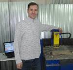
Евгений Александрович Несмеянов
- 15 лет (с 2007 г.) работаю с Mach3. И за это время полностью изучил
все ее нюансы.
- 7 лет (2009 — 2015 гг.) отработал на производстве
технологом-программистом и оператором 3, 4 и 5 осевого фрезерного и токарного
станка под управлением Mach3.
На предприятии ООО «ВоронежПромКомплект»
в г. Воронеж. Подробнее…
- 6 лет (с 2016 г.) успешно настраиваю Mach3 клиентам по России, СНГ и по
другим странам с русскоговорящими клиентами
- Кандидат технических наук в сфере ЧПУ станков. Подробнее…
С КАКИМИ КОНТРОЛЛЕРАМИ И ИНТЕРФЕЙСНЫМИ ПЛАТАМИ Я УЖЕ РАБОТАЛ:
(т.е. на них есть готовые настройки)
|
LPT |
USB |
ETHERNET |
|---|---|---|
|
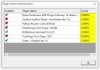
BL-Mach-1.1 Mach3 Interface board StepMaster ver 2.5 Авторские платы с сайтов: * 777russia.ru Каменский станкостроительный завод ТВАЙТ» TWITTE(Каминск-Шахтинск) * Zaxis.ru * Steepline.ru * Сnc-tehnologi.ru PLC4x-G2 PLCM-B1 JP-845, JP-3163B M335-T4 (4-x осевой LPT контроллер в алюминиевом корпусе) TB6560-4V3 — 4 оси, красная плата HK-124528 YOOCNC-NT65-3X LPT-DRV ver.1.02 LPT-DPTR 1.03 MACH MACH3 Control board (V2.1) LPT San. ve Tic. CNCPORTV1
|
BL-USBMach-2.0, 2.1, 2.2, 3.2, 3.3 BSMCEO4U-PP(plus) или RNR USB 2.0 WiXhc USB Motion Card — MK3-V V3.0 WiXHC USB Motion Card — MK3-V V3.1 WiXHC USB Motion Card MK3-V V5.2.6 NVUM USB MACH3 Card (Novusun) UC300 DigitalDream Controller (Novusun) NVCM5V2.1 (Novusun) Mach3 Control Motion Card Контроллеры, работающие под плагинами RnRMotion.dllи NcUsbPod.dll ZKMotion Контроллеры для CNC USB Controller (MK1, MK24) ST-USB MOTION CARD USB Motion Card STB4100 — шумят ШД во время работы Stb5100 USB Motion CARD PLCM-LPT-2 (USB) YOOCNC M3-USB-JB4
YOC-USBM3-V2.2 |
WiXHC Ethernet Motion Card WiXHC Ethernet Motion Card MK6-ET ESS (Ethernet SmoothStepper) PLCM-E3 (Ethernet) PLCM-E1b (Ethernet) NVEM CNC BITSENSOR BSMCI14E Ethernet
|
КАК ПРОИСХОДИТ НАСТРОЙКА MACH3 И СТАНКА:
ВЫ ОТВЕЧАЕТЕ НА 4 ВОПРОСА:
1) Описываете
симптомы не корректной работы станка (например, фреза уходит в сторону или по
глубине)2) Характеристики
ПК3) Фото электроники станка
4) Присылаете архив папки «Mach3»
с диска «С».
Если на этом ПК с Mach3 есть интернет — я настраиваю станок самостоятельно и удаленно, через программу AnyDesk*
Если интернета нет – я пишу инструкцию и присылаю файлы с
настройками. Вы по инструкции копируете файлы и тестируете станок
И КАКОЙ ШАНС, ЧТО ОШИБКА ПРОПАДЕТ?
По моему опыту, через 1-2 дня станок работает исправно
*При условии, что разводка электроники выполнена грамотно и все компоненты исправны. Все элементы системы подходят для стабильной работы станка и решении задачи клиента.
ЦЕНЫ
|
ДЛЯ ФИЗ. ЛИЦ |
ДЛЯ ОРГАНИЗАЦИЙ |
|---|---|
|
11 950 руб В стоимость входит: 1) Настройка 2) Официальная 3) Русификатор для Mach3 4) Тех 5) Гарантия 5 лет на стабильную работу станка. При возникновении проблем я оперативно дам рекомендации по их устранению.
от 8000 руб — отдельно консультации по решению проблем и настройке одного станка и Mach3. Без лицензии и русификатора. Доплата за выполнение срочного заказа +20% к стоимости (Это значит, начинаю работать над вашим станком прямо сейчас) |
23 000 руб — при оплате на карту Сбербанка 29 900 руб — при оплате по безналу. (Выставим счет на оплату.
Все закрывающие документы, акты будут отправлены).
1) Настройка Mach3 и одного станка до результата. 2) Официальная лицензия Mach3 3) Русификатор официальный для Mach3 4) Тех поддержка 3 мес без выходных по тел, WhatsApp или e-mail. 5) Гарантия 5 лет на стабильную работу станка. При возникновении проблем я оперативно дам рекомендации по их устранению. 12 500 руб — отдельно консультации по решению проблем и настройке одного станка и Mach3. Без лицензии и русификатора |
Есть вопросы? Не откладывайте в долгий ящик — задайте их по телефону прямо сейчас: +7-915-548-26-68
I have installed the motion package on my pi (stretch). If I start motion in the foreground it’s working but when I try to start it as a daemon it fails with the following log message:
motion: permission denied for /var/log/motion/motion.log
I’ve seen many approaches to fix this problem by tinkering with the permissions of /var/log/… but this does not convince me.
Q What’s the correct way to fix this problem?
Update
I’ve motion installed as a service and I start it for testing with
sudo service motion start
but even then it fails with the error message below
raspberrypi motion[323]: [0:motion] [ERR] [ALL] myfopen: Error opening file /var/log/motion/motion.log with mode a: Permission denied
asked Feb 2, 2018 at 7:40
![]()
participantparticipant
7812 gold badges6 silver badges20 bronze badges
Gotcha! For testing I started motion with sudo motion -b. Therefore, /var/log/motion/motion.log was written with root:root. After removing /var/log/motion and reboot, the motion-daemon was up and running and had the permission to write to the log.
answered Feb 2, 2018 at 20:53
![]()
participantparticipant
7812 gold badges6 silver badges20 bronze badges
4
There are three ways to fix the problem. All are really the same, just from different angles. That is to make sure that the user starting motion has the access permission to write into the /var/log/motion/ directory. First could just make that user the owner of the directory. And give the owner write access. The second would be start the daemon using root by using the sudo command. An alternative third method is to allow write access to the log directory for a group ‘motion’ and to make that a supplementary group of any user needing to be able to start the daemon.
E.g. Assuming you want to create group motion and add user pi
pi@raspberrypi:~$sudo groupadd motion

  pi@raspberrypi:~$sudo usermod -aG motion pi
Finally change the ownership and permission of the /var/log/motion directory
pi@raspberrypi:~$cd /var/log

 pi@raspberrypi:/var/log $ chown root:motion motion

 pi@raspberrypi:/var/log $ chmod 664 motion
It is simpler and more normal to start the daemon as the root user who should already have all the correct permissions by using sudo command as I already mentioned.
answered Feb 2, 2018 at 15:47
![]()
CharemerCharemer
6154 silver badges11 bronze badges
1
I have tested all answers but no solution. After I reboot the raspberry pi, problem still there. Follow the procedure below to fix the problem.
Create another directory:
sudo mkdir /home/log/motion
Create a log file in this directory:
sudo touch /home/log/motion/motion.log
Change the config file as this new log file:
nano /etc/motion/motion.conf
Add/change this line:
logfile /home/log/motion/motion.log
The important part is adding motion user permission to our new log file because it will run as motion:motion:
sudo chown motion:motion /home/log/motion/motion.log
answered Feb 20, 2020 at 8:05
![]()
M. RostamiM. Rostami
4,2651 gold badge15 silver badges35 bronze badges
3
I made mistake and opened 2 sessions of Motion:
1. Was autostarted with Raspbian
2. Was initiated by me sudo motion
This initiated by me blocked file, sudo rm -rf /var/log/motion/* helped me.
answered May 18, 2019 at 19:31
![]()
KamilKamil
1272 bronze badges
2
As of Raspian Stretch (4.19.27-v7+ #1206) and motion 3.2.12, this also worked:
- created a new directory (
sudo mkdir /tmp/motion) - change permissions (
sudo chown motion:motion /tmp/motion) - change
logfilein/etc/motion/motion.confto point to/tmp/motion(sudo nano /etc/motion/motion.confand addlogfile /tmp/motion) - restart motion (sudo service motion restart).
![]()
M. Rostami
4,2651 gold badge15 silver badges35 bronze badges
answered Mar 31, 2019 at 0:08
![]()
2
Instructions
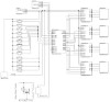
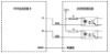
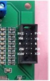
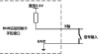
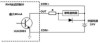
Wiring Diagram
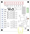
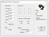
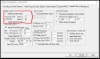
Diagram of the Mach3 USB Controller:
Red Terminals — Step and direction signals to connect to stepper motor drivers.
Yellow — USB Connector
Brown — Status LED
Blue — Input/Output Terminals
Green — Hand wheel connector
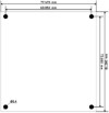
Controller board dimensions:
Mounting dimensions are 69.85 mm in the short side and 73.66 mm in the long side.
Overall board dimensions are 77.47 mm on the short side and 81.28 mm on the long side.
First Use:
For the first time the user of the RNR motion control card will need to make some necessary settings. First, install the Mach3 software and remember where the Mach3 software is installed. Copy the Plugins RnRMotion.dll file to the Mach3 Plugins folder.
Connect one end of the USB cable to the RNR universal motion control card and the other end to a computer. This product adopts the drive-free design. The Windows system can automatically detect the RNR universal motion control card and does not require the user to additionally install the device driver. If you click on the device driver installation icon on the bottom right of the desktop, you will see a pop up window dialog box that should show «RNR ECO MOTION 2.0».
For the first time, the RNR universal motion control card is connected, the system detection takes about 10 seconds. After the system correctly detects the RNR motion control card, the blue LED will light up. In this way, we know that the RNR universal motion control card can be used.
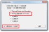
Next, start the Mach3 software. When Mach3 software is started, a pop-up control dialog selection screen will appear.
Select [RnR motion control card -ECO-V2.0] After the above operation, we can use Mach3 software to control our machine tools and other automatic equipment.
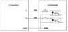
Pulse output:
Connection (step / servo) motor driver RNR motion control card can control 4 motors, respectively named X
axis, Y axis, Z axis, and A axis. Each axis motor control signal has a 2: command pulse signal
P four-axis (a signal corresponding to the «XP», «YP», «ZP» and «AP» and the direction signal D a four-axis (signal corresponds to the «XD «, «YD», «ZD» and «AD»). The motor driver signal Interface usually has a single-ended or differential mode.
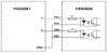
Differential Mode:
For the of the motor to drive in a differential manner, wire the RNR motion control card as
shown in the image.
Single-Ended:
Interface to the single-ended motor driver usually has two forms. The most common type is that one end of its internal signal isolation optocoupler is connected to the internal 5V power supply. This kind of driver input interface is the same as the RNR motion controller card wiring in this image.
Addition Information on the driver signals and the 5v terminal:
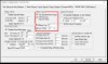
RNR motion control card pulse output ports includes a pair of power output 5V terminals (5V, GND), this provides for 5V DC power supply terminals for the motor driver input interface for wiring. No special requirements, please avoid introducing other power lines on this interface. When an axis direction of movement with the expected direction of motion during reverse operation, the motor output can be altered [(Motor Outputs)] in direction) interface [Mach3Dir Low Active Item to reverse the direction of motion. When a shaft of the motor running, sounds very harsh, the output pulse polarity is not required with the motor driver phase reversed. you can try [(Motor Outputs)] Mach3 changes in configuration interface the [Pulse Low Active (active low pulse)] option to change the output illustrating Pulse polarity.
Note that the RNR motion control card output signal is «1» (high level) at this time , the motor driver optocoupler output signal is «0»; RNR motion control card the output signal is «0» (low when level),the motor driver optocoupler output signal is «1.» Therefore, the Mach3 must be Motor Outputs in configured as Low Active. Configuration methods: Select Menu [Set (Config)], select [port / pin pin (Ports and Pins)], select Motor output (Motor Output)] p, modified as in the image.
Another form of motor controller in single-ended mode, signal isolation optocoupler with one end of the internal connected to the internal power ground. This kind of driver input interface is the same RNR as the wiring diagram of the motion control card in this image.
Slave Axis Setting:
Some mechanical devices adopt the gantry structure which may need a dual motor drive. RNR motion control card may be provided as a slave axis, it can be
specified with the A axis stepper motor to move the gantry. along with the X axis stepper motor.
To set the A axis as a slave axis:
Select the Mach3 menu [(Config)], select [(Slave Axis)], You will see a dialog box as shown in the image
The A axis becomes the slave axis of the X axis. When the X axis moves, the A axis will X move synchronously. When the X-axis performs a home operation, the A-axis is automatically balanced (see the Automatic Homing section).
Input Signals:
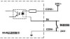
RNR universal motion control card provides four optocoupler isolated signal inputs. As needed,a user can flexibly be defined as input signals the signal on the knife, homing signal, stop signal, the limit switch signal input or user-defined input signal. The signal input circuit of the RNR all-round motion control card is shown as in the image.
The user should connect the COM+ terminal to an externally supplied positive 24V of the 24V DC power supply should be DC power supply; the negative terminal connected to the COM- terminal. When the IN1..IN4 terminal is negative terminal of the 24V power supply shorted to the, the loop is closed and the corresponding input signal is logic «1»; the IN1..IN4 terminal is open and the corresponding input signal is logic «0».

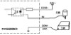
This is a simple sketch of how the limit switches should be connected to the Mach3 USB board. You will need an additional power supply to power this portion of the board. 24V is not necessary. A 12 volt source coming from a PC power supply or AC adapter should suffice.
Wiring for the input signal
The signal input terminal is often connected to the proximity switch, mechanical limit switch or a photoelectric switch. The image shows the wiring for a proximity switch OMRON proximity switch TL-Q5MC2 (TL-Q5MC2 DC 3-wire, the NPN type, the power supply voltage DC12-24V,collector open output)
Photoelectric switches are often used as limit switches or origin/home switches by photoelectric RG150-8(light emitting diode photoelectric switch RG150-8 maximum current 50mA, NPN type open collector output.), For example, RNR versatile motion control card photoelectric switch wiring: in the image
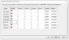
Photoelectric switches are normally open and when the optical gap is blocked, the photoelectric switch is turned off. Therefore, the signal input terminal is always logic «1» and becomes logic «0» when blocked. This is contrary to typical limit switch operation. For this configuration, we must configure the corresponding input terminal to [Active Low via Mach3 software]. The configuration method is: select the menu [Config], select [Ports and Pins], and then select [Input Signals] Page, as shown in the image.
It is assumed that the user will connect the photoelectric switch to the IN1 terminal as the X-axis limit switch. At this point, you should check the Active Low of X++ and X-.
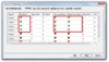
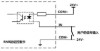
Emergency Stop Button
When the user presses the [Emergency Stop] button during processing, the machining process will be terminated immediately. This eliminates accidents the first time they occur. For safety reasons, we strongly recommend that you add an external input (IN1..IN4) terminal to the emergency stop button. The Emergency stop button wiring diagram as shown in the image.
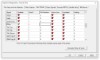
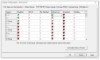
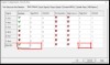
Assume that the user connects the emergency stop button to the IN1 terminal. Accordingly, we need in to make configuration Mach3 software. The configuration method is: Select [Config], select [Ports and Pins], and select [Input Signals] page. Pull down the scroll bar, find the line with the name [Signal] [EStop],line of the Estop line check the [Enable], and set the Port # to 3. Port 3 is set means that the signal is processed by the RNR motion control card. Other port numbers indicate that this signal is not related to the RNR motion control card. Setting the Pin Number to «1» means that this signal is connected to the IN1 of the RNR Motion Control Card terminal. After the configuration is
complete, click OK.
Try running some G-Code and press the emergency stop button on the terminal IN1. Observe that the machine will stop.
Limit
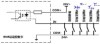
When the limit switch is activated, the machining process will terminate immediately. This can effectively prevent the tool from moving outside the work area and cause danger. This is the same effect as pressing the emergency stop button. Therefore, we recommend that users connect limit switches. In order to only use a single input terminal, all of the switches can be wired in NO (Normally Open) configuration to the same signal input terminal. Limit switches are wired as shown in the image.
The assumption here is that the limit switch connected to the terminals IN1, then the configuration is as follows: Click Config, select (Ports and Pins), and then select (Input Signals). Pull down the scroll bar and find the [Signal] name [X++ (X axis positive limit)], [X—(X axis negative limit position)], [Y++ (Y axis positive limit position)], [Y—( Y-axis negative limit)], [Z ++ (Z-axis positive limit)] and other lines, the Enable [check]the {port # (port) is set to 3], the [Pin number (pin number)] is provided Is «1». As shown in the image.
Note that if the selected limit switch is a photoelectric switch, since the photoelectric switch is normally open, reference should also be a content of «input terminal wiring», the corresponding [active low (active low)]checked. In addition, when wiring, the switches are not connected in parallel, but instead should be
connected in series
The Automatic Return to the Origin or Homing
RNR motion control card supports the automatic return to origin function of each axis. The automatic return to each axis origin consists of four consecutive stages.
First stage is based on the set direction, with G0 (axis’s rapid traverse) rate the percentage as given by the [Speed%] parameter in Mach3 towards the origin until it touches the origin switch;
Second stage: G0 rate from the origin switch, is set to fall back from the stop;
Third stage: the rate of movement at a rate of 1/10 of the first stage, gradually toward the moving origin,the origin until the touch switch stops with touches the origin switch at a very slow rate to ensure the accuracy of the origin;
Fourth Stage: In the same stage as the second stage, it will stop at the G0 rate after going back to the set distance. This ensures that the axis completely leaves the origin switch.
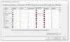
As described in the «limit switch setting» in the previous section, in order to use only one input terminal, the origin switches of the four axes can be connected in parallel and share one input signal terminal (IN1..IN4).
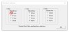
Mach3 software must be configured accordingly for the parallel normally open wiring configuration. It is assumed that the origin or home switch is connected to the IN2 terminal. The configuration method is: at the menu [Config], select [Ports and Pins], and then select the [Input Signals] page. Pull down the scroll bar to find the [Signal] names [X Home (X-axis home switch)], [Y Home (Y-axis home switch)], [Z Home (Z-axis home switch)], [A Home (A-axis origin) Switch)], select [Enable] to select [Port #] as «3» and [Pin Number] as «2». As shown in the figure:
Homing rate configuration method
Select the menu (Config), select (Homing / Limits) in [motor homing / Soft Limits)] (Motor Home / interface, find the line where the axis is located. Modify by changing[Speed %] the value. For example, we expect to perform with 50% of the G0 (Axis Rapid Move) rate homing, then set [Speed %] to «50». When returning to the origin, the direction of the axis movement is related to the position of the origin switch. If the origin switch is mounted on one end of the negative axis of the shaft, the [Home Neg] item should be checked. If the origin point switch is installed on one end of the positive axis of the shaft, [Home Neg] should be crossed as shown in the image
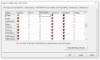
The second and fourth phases of the automatic return to origin process are the back-off phase after returning to the origin. Set distance fallback method is: select the menu (Config), select (Config Plugins).
In the pop-up window, find the [RnR Motion Control Card-ECO-V2.0] line and click [CONFIG] to display the [RNR Universal Motion Control Card Parameter Settings] dialog box.
In the Return to Zero setting box, change the back-off distance for each axis. As shown in the image, change the axes to «0.8». In this way, the return distance is «0.8» units when you return to the origin. Also, click the pull off checkbox to enable the pull off. Setup is completed, do not forget to click [Save].
The Automatic Origin Homing of Axis with Slave Axis
The axis and its corresponding axis of the slave axis must be equipped with a home switch, and the origin slave axis and the origin switch of the switch of its corresponding axis should be connected from the two signal input terminals. Here assumed is that the slave axis A-axis is the X axis, the X axis is mounted a home switch, A shaft is home switch mounted. When the X-axis performs a home operation, in the first stage, both the X-axis and the A-axis move toward the origin. The axis that first hits the origin switch will stop moving, and the other axis will continue to move until it touches the origin switch. The third stage is similar to the first stage. In this way, the two axes are balanced when they are automatically returned to the origin.
The automatic tool setting
RNR motion control card supports the automatic tool setting function. In Mach3, automatic tool setting can be used to automatically measure and compensate the tool length, position the workpiece, find the center of the workpiece, and find the center point of the workpiece. To use the automatic tool setting, an RNR universal motion controller card needs a signal input terminal (IN1..IN4) to be attached to the tool setter. This setter is also called a Z-Axis touch plate. The nature of the tool holder is a micro switch. Therefore, the self-made touch plate is very simple. Two wires, a connecting tool or edge finder, a connection to a single-sided printed circuit board or a connected workpiece. When the tool or edge finder hits circuit board the copper layer or metal workpiece, the line is turned on and the tool setting signal input is completed.
Select an input signal at an input signal terminal IN1..IN4 signal as a touch plate.
Assuming the input signal is selected as a terminal IN1 signal input tool. The setting method in Mach3 is: select [Config], select [Ports and Pins], and then select [Input Signals] page. Find the line where [Signal] is [Probe], check the [Enable] item, modify [Port #] to «3», and modify [Pin Number] to «1».
In Mach3, the specific tool setting process is accomplished through VBScript script code. VBScript script code requires the user to write according to the actual situation. Many VB scripts can be found on the internet. You will need to customize the code for your application.
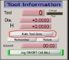
Automatic Tool Clearing
Automatic tool clearing function helps the user to remove the tool length and workpiece thickness, and the Z defines the zero coordinate of axis to the machining surface of the workpiece. Mach3 does not provide automatic zeroing for the script code. We need to program the automatic tool zeroing function. Programming steps: Select menu (Operator) and select (Edit Button Script), and then find the (Program Run) screen, click (Auto Tool Zero) button.
As shown in the figure, Mach3 will pop up the scripting window, as shown in the
image.
Delete the original script code in the window and replace it with code that will work for your application.
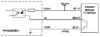
The Handwheel Interface
RNR motion control card provides a handwheel interface to the user-supplied handwheel. Note that the handwheel interface has a withstand voltage of 5V, so only connect DC 5V powered handwheels. When the handwheel interface input exceeds 5V, it will cause damage to RNR’s motion control card.
Below Each pin is described as follows:
— 5V positive and 5V negative: DC 5V power supply is available, which can be used to supply power to the handwheel
— X-axis, Y-axis, Z-axis, A-axis : a shaft connected to the hand wheel switch, used to select the desired axis jog
— A and B: connecting the hand wheel encoder outputs A and B
— X10: handwheel rate 10 times magnification
— X100: handwheel The rate100x
Enhancement handwheel interface is compatible with Weihong system handwheels.
WeiHong handwheel 15 Plug pin numbers. Weihong Handwheel Pin Definitions Connect to Handwheel Interface
1 VCC,L+ 5V Positive
2 A — A
3 B — B
4 Empty
5 Empty
6 X1
7 X10 — X10
8 X100 — X100
9 4 Axis — A Axis
10 Empty
11 COM Terminal, 0V,L — 5V Negative
12 Empty
13 Z Axis — Z Axis
14 Y Axis — Y Axis
15 X Axis — X Axis
Mach3 Handwheel Setting
Connecting the handwheel, the Mach3 must be set to enable handwheel jogging. Setup method: Select Menu [Set (Config)], select (Ports and Pins), select (Encoder / MPG «s) page, the [MPG # 1} [Enable] is checked, as shown in the image.
Press [OK] to save the setting
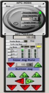
Press [Tab] on the keyboard to call out the Mach3 Handwheel control.
Click the [Jog Mode] button to switch the jog mode to [MPG (Handwheel)] mode and tap [Alt A] to switch the X axis selection as shown above. Gently rotate the handwheel encoder to see if it can control X-axis movement.
Handwheel Interface as an Extended Input Signal
If you do not need to connect a handwheel, you can use the handwheel interface as extra input signals. The handwheel conector will provide 8 more input signals, and with the previous 4 signal inputs IN1..IN4, will provide a total of 12 input signals.
The signal input hand wheel interface correspond to the terminals of the following:
— X axis: IN5
— Y axis: IN6
— Z Axis: IN7
— A axis: IN8
— X10: IN9
— X100:IN10
— A:IN11
— B:IN12
Note: IN5..IN12 handwheel input terminal does not support the interface corresponding to the limit or homing position, tool setting, only as a regular input of the switch used (typically used as a connection control panel). wiring signal input to the X-axis, for example, we need the X-axis access to Input signal internal Interface schematic principle handwheel As follows:
When the signal input switch is closed and shorted to ground, the logic signal «1» is input to the X axis. We select the Mach3 menu [Config] and select [Ports and Pins] and then select the [Input Signals] page. Drag the scroll bar to find the line where [Signal] is [Input #1],[Enable] select, and change [Port #] to For «3», change the [Pin Number] to «5» so that the Mach3 input signal [Input #1] corresponds to the input of the handwheel X. Select the
Look at the Diagnostics page of Mach 3. When you close the X axis external switch, you will see Input 1] Display turns green.
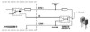
Output Signals
RNR motion control card provides four optocoupler isolated outputs. An output terminal adopt Darlington ULN2003, capable of driving an external relay or indicator. Drive capacity is 60mA. Wiring of output signal to relay.
COM+ and COM- of the signal output terminal block respectively connect the positive and 24V DC power supply negative poles of the. The output terminals OUT1..OUT4 are connected to the relay coil via a current limiting resistor (relay the other end of the coil is connected to the positive terminal of the 24V power supply). Wherein the resistance of the current limiting resistor based on requested relay.
Spindle Motor Control
Mach3 supports spindle motor control. Mach3 offers three spindle motor control methods.
The first is relay mode. Mach3 outputs control signals through two signal output terminals.
The second is the PWM mode. In this mode, Mach3 through the signal output outputs the PWM signal with a certain duty cycle output terminal that will create a (DC) spindle motor speed control.
The third method is the pulse method, which is mainly used to control the servo motor. The RNR motion control card does not support this mode.
Spindle Control in Relay Mode
The relay mode, the spindle motor drive signal output terminal using two relay switches on or off to achieve reversing the spindle motor. Suppose we need the signal output terminal OUT1 to drive the motor forward rotation relay and the signal output terminal OUT2 to drive the motor reversal relay. In Mach3, select the menu [Config], select [Ports and Pins], and select the [Spindle Setup] in the popup dialog page. In (Relay Control) box, ensure that (disabled Spindle relays) is not checked; in [clockwise output # (Clockwise Output)] Fill «1»; counterclockwise in [ Output # (CCW Output) and fill in «2».
Press [OK] button to save the settings. The user can connect the indicator OUT1 and OUT2 (refer to the previous section) for debugging. When the program «M3» is executed, OUT1 output signal will be seen; when the program «M4» is executed, the OUT2 output signal will be seen; when the program «M5» is executed, the OUT1 and OUT2 are turned off. Use the MDI page to enter the M3, M4 and M5 codes.
PWM Mode
Suppose we need to output PWM (pulse width modulation) signal on terminal OUT3 to drive the spindle motor power supply relay, motor speed adjustment is achieved. In Mach3: Select [Config], select [Ports and Pins], and select [Spindle Setup] page in the popup dialog box. In the Motor Control box, check Use Spindle Motor Output and select PWM Control.
[Use spindle motor output] is checked, Mach3 will automatically enable the spindle motor output pin. Click OK when the pop-up happens that will say «Spindle Motor has now been enabled. Ensure you set its pinouts.
Next, select the Motor Outputs tab. At the line where [Signal] is [Spindle], check [Enable], modify [Step Port] to «3», modify [Step Pin#] to «3», and specify OUT3 as Is the output terminal of the PWM.
Press [OK] button to save. Connect the indicator (refer to the previous section) to OUT3 for debugging. When the program «M3″executed is, OUT3 output signal can be seen
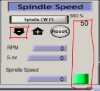
In Mach3’s [Program Run] page, click on the green [Spindle Speed] bar in [and change the value of [SRO%] to be less than [100%].
In this case, it can be observed OUT3 external indicator starts blinking in the diagnostics page (PWM output signal).
The Output of Other Signals
The signal terminal can be assigned to output pins OUT1..OUT4 in Mach3 from the script and can be manipulated in Mach3. For example, we need to assign OUT4 to Mach3’s [OUTPUT#1]. Setting method: Select [Config], select [Ports and Pins], and select [in the popup dialog box Output Signals] page. Find the line where [Signal] is [Output #1], check [Enable], modify [Port #] to «3», and modify [Pin Number] to «4». When the changes are made, click OK to save.