На чтение 6 мин Просмотров 6.5к.
Рассмотрим подробнее
- Техническое описание и расшифровка ошибки P0235
- Симптомы неисправности
- Причины возникновения ошибки
- Как устранить или сбросить код неисправности P0235
- Диагностика и решение проблем
- Проверка вакуума
- Замер давления наддува, осмотр турбонагнетателя
- Датчик и проводка
- На каких автомобилях чаще встречается данная проблема
- Видео
Код ошибки P0235 звучит как «неисправность цепи датчика «A» давления наддува турбокомпрессора». Часто, в программах, работающих со сканером OBD-2, название может иметь английское написание «Turbocharger Boost Sensor «A» Circuit Malfunction».
Техническое описание и расшифровка ошибки P0235
Код неисправности OBD-II P0235 является общим, чаще всего определяется как неисправность цепи датчика «A» давления турбонаддува. Устанавливается, когда модуль управления трансмиссией (PCM) обнаруживает общую неисправность в цепи управления форсированной индукцией.
Независимо от специфики используемого устройства (турбонагнетатель / нагнетатель). Целью является увеличение выходной мощности двигателя без использования значительно большего количества топлива. Хотя принудительная индукция широко используется, эта технология особенно полезна для двигателей небольшой мощности. Поскольку дает огромный прирост мощности при относительно низких затратах. А также без значительных потерь с точки зрения веса и расхода топлива.
Однако, давление наддува необходимо контролировать, как для получения максимальной пользы, так и для защиты двигателя от воздействий чрезмерного давления. Для этого турбонагнетатели используют встроенные механические устройства для сброса избыточного давления. Эти устройства управляются электронным управлением PCM, поэтому давление наддува, никогда не превышает максимально допустимый предел.
Для эффективного управления наддувом, PCM использует первичные входные данные от датчика абсолютного давления в коллекторе (MAP). Затем это значение сравнивается с входными данными датчика частоты вращения двигателя. А также датчиками температуры всасываемого воздуха (IAT) и положения дроссельной заслонки (TPS).
Если система управления наддувом полностью функциональна, то PCM будет использовать совокупные входные данные от всех задействованных датчиков. Однако, если схема управления наддувом выходит из строя, PCM больше не может эффективно управлять давлением наддува.
Поэтому устанавливается код P0235 и в результате загорится сигнальная лампа. Обратите внимание, что в зависимости от характера проблемы, PCM может также устанавливать дополнительные коды. Некоторые из которых могут привести к переходу в отказоустойчивый или аварийный режим. Делается это в качестве меры предосторожности, а также для защиты двигателя.
Симптомы неисправности
Основным симптомом появления ошибки P0235 для водителя является подсветка MIL (индикатор неисправности). Также его называют Check engine или просто «горит чек».
Также они могут проявляться как:
- Загорится контрольная лампа «Check engine» на панели управления (код будет записан в память как неисправность).
- Может наблюдаться потеря мощности из-за отключения турбонаддува двигателя.
- Увеличенный шум, также может присутствовать звон и дребезжание турбокомпрессора или трубопроводов.
- Преждевременное зажигание, как следствие, ощутимая детонация.
- Дерганье/пропуски зажигания.
- Перегрев двигателя с последующими проблемами.
- Загрязнение свечей зажигания.
- Двигателю может не хватать мощности во время разгона.
Степень серьезности кода P0235 средняя, но нужно понимать, что при повышении давления турбонаддува увеличивается мощность двигателя. Если датчик давления наддува турбокомпрессора выйдет из строя, то PCM автомобиля может отключить турбонаддув. Это приведет к падению мощности двигателя.
Причины возникновения ошибки
Код P0235 может означать, что произошла одна или несколько следующих проблем:
- Неисправен датчик давления наддува турбокомпрессора.
- Повреждены, сожжены, закорочены, отсоединены, корродированы провода или разъемы датчика давления наддува.
- Короткое замыкание или разрыв в жгуте проводов датчика между датчиком и PCM.
- Поврежденные, сломанные, треснувшие или смещенные вакуумные трубки.
- Недостаточная подача масла к подшипнику главного вала.
- Неисправный перепускной клапан.
- Отказ подшипника, вызывающий медленное раскручивание из-за сопротивления.
- Зазубрины, погнутые или отсутствующие лопатки турбины, вызывающие дисбаланс.
- Утечка сальника на стороне компрессора турбонагнетателя.
- Поврежденное или неисправное устройство сброса давления наддува.
- Иногда причиной является неисправный модуль PCM.
Как устранить или сбросить код неисправности P0235
Некоторые предлагаемые шаги для устранения неполадок и исправления кода ошибки P0235:
- Считайте все сохраненные данные и коды ошибок с помощью сканера OBD-II.
- Очистите коды ошибок с памяти компьютера и проведите тест-драйв автомобиля, чтобы выяснить, появляется ли ошибка P0235 снова.
- Проверьте работу датчика давления наддува турбокомпрессора, сравнив его показания с показаниями датчика абсолютного давления в коллекторе.
- Осмотрите датчик давления наддува турбокомпрессора на предмет засорения.
- Протестируйте разъем и проводку на наличие повреждений, ослабления и коррозии.
Диагностика и решение проблем
Турбины обычно вращаются с невероятной скоростью от 100 000 до 150 000 оборотов в минуту. Они не терпимы к дисбалансу или отсутствию чистого масла в подшипнике.
Процесс диагностики при ошибке P0235 лучше начать с наиболее распространенных проблем с турбонаддувом. Для их проведения понадобятся инструменты, такие как вакуумметр и циферблатный индикатор.
Проверка вакуума
Убедитесь, что двигатель работает должным образом, без пропусков зажигания и кодов, относящихся к неисправному датчику детонации. Затем, проверьте герметичность хомутов на выходе турбонагнетателя, промежуточного охладителя, а также корпусе дроссельной заслонки.
Осмотрите впускной коллектор на предмет утечек любого рода, включая вакуумные шланги. Снимите рычаг с перепускной заслонки. Вручную управляйте клапаном, ища заедание клапана, вызывающее падение наддува.
Замер давления наддува, осмотр турбонагнетателя
Найдите вакуум без отверстий во впускном коллекторе и установите вакуумметр. Запустите двигатель. На холостом ходу двигатель должен иметь разрежение 1-1.5 атмосферы. Если меньше 1 атмосферы, значит каталитический нейтрализатор неисправен и не позволяет наращивать наддув.
Быстро разгоните двигатель до 5000 об / мин и отпустите дроссельную заслонку, наблюдая за вакуумметром, показывающим давление наддува. Если давление наддува поднимается выше 1.3 атмосферы, значит плохой перепускной клапан.
Заглушите двигатель и дайте ему остыть. Снимите выпускной шланг турбины и загляните внутрь, чтобы убедиться, что лопасти не задевают корпус. Ищите погнутые или отсутствующие лопасти или масло в турбонагнетателе. Вращайте лопасти вручную, ищите сопротивление, указывающее на неисправность турбонагнетателя.
Осмотрите маслопроводы от блока цилиндров к центральному подшипнику и возвратный трубопровод от подшипника к масляному поддону на предмет утечек. Установите циферблатный индикатор на выходной патрубок турбины, прокрутите вал турбины. Если осевой люфт превышает 0,003, центральный подшипник неисправен.
Датчик и проводка
Если после всех проверок проблемы не обнаружены, но код P0235 не пропал, необходимо проверить электрические компоненты. Нужно протестировать датчик наддува и жгут проводов с помощью вольтомметра. Убедитесь, что на датчик приходит 5 вольт от PCM к датчику.
Отсутствие напряжения означает обрыв или короткое замыкание в жгуте проводов. Также может быть неисправен PCM. Найдите опорный сигнал от датчика наддува к блоку управления двигателем и убедитесь, что напряжение меняется по мере увеличения числа оборотов. Отсутствие скачка напряжения указывает на неисправный датчик.
На каких автомобилях чаще встречается данная проблема
Проблема с кодом P0235 может встречаться на различных машинах, но всегда есть статистика, на каких марках эта ошибка присутствует чаще. Вот список некоторых из них:
- Alfa Romeo (Альфа-Ромео 156)
- Audi (Ауди а6)
- Chrysler
- Citroen (Ситроен С5, Джампер)
- Fiat (Фиат Дукато, Мареа, Пунто)
- Ford (Форд Мондео, Транзит)
- Honda (Хонда Паспорт)
- Jeep (Джип Гранд Чероки)
- Land Rover (Ленд Ровер Дискавери, Рендж Ровер)
- Mercedes (Мерседес 230 slk)
- Nissan (Ниссан Х-Трейл)
- Opel (Опель Астра, Виваро)
- Peugeot (Пежо 406, 607, Боксер)
- Renault (Рено Лагуна, Сценик)
- Volkswagen (Фольксваген Туарег)
- Volvo
С кодом неисправности Р0235 иногда можно встретить и другие ошибки. Наиболее часто встречаются следующие: P0239, P0300, P0706, P3348, C0237, C0246, C0252.
Видео
Перейти к содержанию
На чтение 3 мин Просмотров 125 Опубликовано 19.02.2020
Содержание
- Определение кода ошибки P0235
- Что означает ошибка P0235
- Причины возникновения ошибки P0235
- Каковы симптомы ошибки P0235?
- Как механик диагностирует ошибку P0235?
- Общие ошибки при диагностировании кода P0235
- Насколько серьезной является ошибка P0235?
- Какой ремонт может исправить ошибку P0235?
- Дополнительные комментарии для устранения ошибки P0235
Определение кода ошибки P0235
Ошибка P0235 указывает на неисправность электрической цепи датчика “А” давления наддува турбокомпрессора.
Что означает ошибка P0235
Ошибка P0235 является общим кодом ошибки, который указывает на то, что модуль управления двигателем (ECM) обнаружил, что показания датчика “А” давления наддува турбокомпрессора не соотносятся с показаниями коллекторного датчика абсолютного давления во время работы двигателя на холостом ходу или при включенном зажигании и выключенном двигателе.
Причины возникновения ошибки P0235
- Несоответствие показаний датчика “А” давления наддува турбокомпрессора и коллекторного датчика абсолютного давления во время работы двигателя на холостом ходу или при включенном зажигании и выключенном двигателе
- Засорение датчика “А” давлениянаддуватурбокомпрессора
- Медленная реакция датчика “А” давления наддува турбокомпрессора на изменение давления
Каковы симптомы ошибки P0235?
- В памяти ECM сохранится ошибка P0235 и на приборной панели автомобиля загорится индикатор Check Engine
- ECM автомобиля может отключить турбонаддув, что, в вою очередь, может привести к падению мощности двигателя
- Также мощность двигателя может снизиться при ускорении автомобиля, если датчик давления наддува не сможет правильно зафиксировать давление наддува
Как механик диагностирует ошибку P0235?
При диагностировании данной ошибки механик выполнит следующее:
- Считает все сохраненные данные и коды ошибок с помощью сканера OBD-II
- Очистит коды ошибок с памяти компьютера и проведет тест-драйв автомобиля, чтобы выяснить, появляется ли ошибка P0235 снова
- Проверит работу датчика “А” давления наддува турбокомпрессора, сравнив его показания с показаниями коллекторного датчика абсолютного давления
- Проверит датчик “А” давления наддува турбокомпрессора на предмет засорения
- Проверит разъем датчика “А” давления наддува турбокомпрессора на предмет ослабления и наличия коррозии
Общие ошибки при диагностировании кода P0235
Наиболее распространенными ошибками при диагностировании данного кода являются:
- Пренебрежение проверкой шланга датчика давления наддува турбокомпрессора на предмет засорения и наличия повреждений
- Пренебрежение проверкой разъема датчика давления наддува турбокомпрессора на предмет ослабления и наличия повреждений
Насколько серьезной является ошибка P0235?
- При повышении давления наддува увеличивается мощность двигателя. Если датчик давления наддува турбокомпрессора выйдет из строя, ECM автомобиля может отключить турбонаддув, что, в вою очередь, приведет к падению мощности двигателя.
Какой ремонт может исправить ошибку P0235?
- Замена датчика давления наддува, если датчик отправляет неверные показания на ECM
- Ремонт или замена изношенного или засоренного шланга датчика давления наддува или поврежденного разъема датчика
Дополнительные комментарии для устранения ошибки P0235
Ошибка P0235 указывает на наличие неисправности в электрической цепи датчика “А” давления наддува турбокомпрессора. Наиболее распространенной причиной возникновения ошибки является неисправность самого датчика.
987
Low power/boost on Ford TDCi engine
On our last trip to France, our van experienced what appeared to be a major fault, such that it struggled going up hills which is unheard of for these vans! It was as if the turbo wasn’t working properly, or for whatever reason the van was sluggish as pie. We did some basic checks in France and decided it was safe to continue till we got back to UK for further diagnosis. This diagnosis was VERY thorough and as this seems to be a “common” fault I decided to write up all the tests so they could be useful for someone (and me!) should similar happen again.
What I found was that there were many trivial problems that could cause this (or similar) issue.
My “problem” and “fix”
My particular issue was, would you believe, caused by *someone* swapping the EGR and Turbo Actuator Vacuum hoses around (!!!) – a
Not saying it 100% was them, but i
The fix (once found) took 30 seconds to put right, simply by swapping the vacuum hoses back to the right connectors. No harm done, just frustraiting!
In future, I will be photographing the engine before leaving the van anywhere, not just the exterior which I used to do!
Thanks and Credit
This article will hopefully be useful to someone, but beyond typing it I cannot take all the credit. Some friends helped me out for advice, and a number of guys on FordTransit.org forum gave me pointers, accurate information, specific information and tips – one of which identified the swapped pipes. Without these guys, I’d have been lumbered with a huge bill from a garage (possibly the same one mentioned above) for diagnostics and fixes.
I strongly recommend that if you have a transit and an issue, then chat to the guys on FordTransit.org – and search their archives as there is a HUGE amount of information there, and lots of willing people who know a lot (and I mean a LOT) more than me.
Disclaimer
I am an IT guru, I am not a mechanic. The information here is specific to my van, a 2005 Mk6 Ford Transit SWB280 FWD 2L TDCi. Whilst I know some information is common between other TDCi variants, the specifics are ONLY for ME AND MY VAN. If you decide to use MY PERSONAL NOTES on your van, please be aware this is entirely at your risk and of course you should not believe anything I say and you should take your van to a trusted garage! Do not attempt to do anything that I have!
Characteristics of fault
Bizzarely, the van drove quite well – on the flat (Wiltshire!) it drove fine, felt maybe slightly down on power, but really nothing to worry about. Of course its a campervan so we don’t thrash it or drive fast. MPG same as normal (mid 30’s), starts first-time every time, and idles fine.
The main way to notice the fault were:-
- At 3200rpm, when static on drive, the van would stutter (as if on a limiter) and smoke before exceeding 3200rpm. When driven, this was fine.
- Going up-hill or on overtakes when power was required, it was flat. It’d still get up the hills but slower and a gear lower (e.g. feeling like an old van)
- No extra smoke or noise.
Note I did NOT have a MIL (engine management) warning light on the dash at first. Only after I paid Ford £90 to update the ECU to the latest software was the fault detected. Once the new software was on, the van entered LHM (Limp Home Mode) so was worse to drive (doh!) – with the error being “p0235 turbocharger boost sensor a malfunction”. At least this helped focus the mind….
(If you have issues starting, or a rough idle, you are likely to have other problems than here)
Possible areas to check
Here is a list of checks I did, each is explained further down the page
- Brakes
- Fuel Pump / Injectors
- F-Super Diagnostics
- MAP Sensor
- MAP Sensor wiring
- MAF Sensor
- MAF Sensor Wiring
- Fuel Filter
- Air Filter
- Turbo (Inlet)
- Turbo boost pipes
- Inlet Manifold
- Intercooler
- EGR
- Vacuum pump
- VNT Actuator
- VNT Vacuum pipework
- VNT Solenoid
- ECU Reset
- Cat/Exhaust
Tools and stuff to buy
I bought the following tools to help me sort this out, and they were necessary! (the links are to the items on Amazon, if you click and buy, I get 5% sales comission from Amazon. I bought some stuff from Amazon and some elsewhere.)
- : This interface and software allows a Windows Laptop to talk to the Transit ECU and read/reset error codes, and also to see sensor readings. This is pretty much essential for diagnoising issues. Its not as good as Fords system (£1800!) but good to do quite a bit with!
- : This tool is essential to undo (and do up) the hose clips that latch on. Yeah – you can do it with a screwdriver and pliers and a lot of swearing, but this tool makes it simple!
- Multimeter and Piercing Probes: Essential for wire checking
- : Replacement MAP sensor if yours has failed. Of course, check part number. NO NEED to buy direct from Ford – a genuine Ford garage quoted me £380 for the part as they refused to sell just the sensor, only as part of a new intercooler!!!
- : Essential test kit to test the MAP sensor, vacuum pipes and the actuation of the VNT turbo. Godsend!
NOTES
- If you do continuity tests on wires/sensors, best to have the battery disconnected to save ECU
- Unplugging pipes/sensors as part of the diagnostics may trigger other fault codes (e..g disconnect a sensor, you may get sensor fault; disconnect a pipe you may get airflow fault). f-super deals with this
- Don’t trust Ford entirely – their engineer didn’t find the swapped hoses (despite being told low/no boost; and despite having a computer that could test turbo actuation – which would instantly show it didn’t move when expected which would quickly show the swapped pipe!)
- These are MY NOTES – they may be useful for Transit or Mondeo TDCi engines or other engines, but don’t take them as gospel!
P0235 error
After my ECU update and the newer software detecting a fault, the van then moaned about P0235 – “turbocharger boost sensor A malfunction”. What this really means is “the data I am getting from the
1.Brakes
Silly as it sounds, check all 4 corners and ensure your brakes aren’t sticking/binding. If they are, this can give the impression of lack of power.
2.Fuel Pump / Injectors
Fortunately I didn’t need to examine these, but these can be a cause of low power. However, from my research a fault with either of these would typically flag a DTC identifying them, or you would have other symptoms – like poor starting or idle. This subsystem is quite complex, and almost certinly left to an expert.
3.F-Super Diagnostics
is a rather good, and cheap, interface to allow you to see information that your ECU knows. So, such informaton can include temperature, RPM, boost pressure, fuel pressue etc. 
The interface port is under the steering wheel.
A point to note, my late Mk6 didn’t flag any error codes, but after a trip to Ford and £90 later, they updated the ECU software and the newer software did indeed flag a code (and put the van into limp mode 🙁 ) – however this did help me diagnose where to focus my attention even if Ford read the code and insisted the MAP sensor was faulty (even though I didn’t think it was).
Anyway…
With f-super, some key bit of information:-
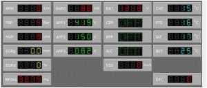
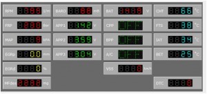
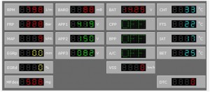
- BARO is air pressure, and is out by a factor of 10. So 100 is roughly 1000mb. (MAP sensor). Should be roughtly 99-101 depending on the weather and altitude. Note on images mine is 88 – thats because I was up in the Alps!
- MAP is manifold absolute pressure, and is in effect boost pressure. It is in effect a factor of 100 out! (see MAP sensor). On idle, it should match BARO (x10), and on revving to 2-3000 revs should read up to 14. (Boost pressure in PSI = (( 10xMAP ) – BARO ) x 0.145. So, if BARO = 100, and MAP = 14, then PSI = ( (10 x 14) -100 ) x 0.145 = (140 – 100) x 0.145 = 40 x 0.145 = 5.8 psi boost
- IAT is inlet air temperature (from MAP sensor which is actually a T-MAP sensor)
- APP1-3 is throttle position
- FRP = fuel rail pressure
- MFdes is metered fuel
The rest of the readings are obvious, so look at what they are. The temperatures should all be logically correct.
I’ve included some images of f-super on my van which may be useful to compare – the only thing to rememeber is these were taken in the Alps when the turbo wasn’t connected properly, so MAP (aka “boost”) will be a lot lower than it should be.

4.MAP Sensor
Ford, in their £90 diagnostic session where they failed to test the turbo actuator or notice the vacuum pipes were wrong, simply saw the P0235 error and said it was a faultly MAP sensor. After trying to charge me £380 for a new sensor and intercooler I bought just the sensor from a parts place opposite, fitted it in 2 mins, proved it wasn’t it – and then was told “tough – come back another time to continue diagnostics”….
Anyway, the MAP sensor is a TMAP sensor which reads boost pressure, air temperature, and also atmospheric pressure. Absolutely no idea how it does the latter….
Removal
This is located on the off-site pipe at the bottom of the intercooler. It comes off simply with 2 star-shape (torx) screws. The electrical connector unplugs. On other vans this is near the EGR and hence gets gunked up – so if its dirty, 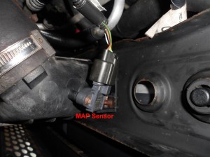
Tests
Anyway, using the
and some DIY scraps, you can make up some pipework to plug the MAP sensor in (when off the van, but connected electically). You can then run
and then change the pressure in a vacuum. Removing 500mb of pressure should make the MAP reading in f-super read 5. In addition I used a bike inner-tube (cut) to put the MAP under pressure, and putting 10psi pressure around the MAP sensor probe, you should get a reading of 17 or so on f-super. (see f-super section for accurate maths)
You can also directly check voltages (thanks to Dan @ FordTransit.org)
The map sensor loom has 4 pins;
1. MAP reading
2. 5v reference
3. IAT reading
4. Earth
So… With ignition on pin 2 should read 5v and pin 1 should read 1.5v
At engine idle pin 1 should still read 1.5v, with a little throttle the voltages will increase to about 3.9v roughly.
Pin 4 should earth with no resistance (0 ohm)
Discount pin 3 as it works the iat sensor.
5.MAP Sensor wiring
On the forums, and a friends experience, the wiring to the MAP sensor can corrode or wear through. If you clean the sensor wires you can see they are colour marked – make note of these. Note each wire has a PRIMARY colour and then a thinner SECONDARY stripe. This is important – white with green stripe looks similar to, but is different to green with white stripe!
The wires go into a loom and cover, up near the radiator, under the AC pipes, behind the air-filter housing, across the windscreen to the ECU on the near-side top part of the engine above the coolant bottle.
Tests
- Check the wiring to the plug
- Open and check the loom from the MAP sensor up – reports of corossion up to 10cm away from plug
- Check wiring behind air-filter housing (a bitch to get to if you have AC and after market cruise control!) – a friends had worn through here due to bad fitting at Ford.
- I personally openned the loom near the ECU (tape unwraps), found each of the 4x MAP wires, and with BATTERY DISCONNECTED I checked continuity between here and the plug (using automotive piercing probes), also I checked for shorts to ground, all whilst wrigging the cable along its entire route.
So its essential that there is 100% continuity at all times, and there are no shorts to earth. The exception is Pin 4 which should be earth and 100% continuity to earth at both ends.
6.MAF Sensor
The MAF sensor measures air flow being sucked in via the air filter housing. The ECU
Removal
This is simply held in with 2 torx screws. Once removed be gentle as the element is very very fragile.
Tests
If you think you have a faulty MAF, the “internet says” to simply disconnect it! The ECU will revert to a safe program assuming safe settings for what the MAF should be. If the van drives the same/better, then the MAF is faulty. If it drives worse – it isn’t!
You can clean the element – gently – with a cotton bud and electrical cleaner.
You can test the voltages on the sensor and you should get, roughly:-
- Pin 2 (to earth): 12v (12-14v)
- Pin 5 to earth, on idle, 1.7v
- Pin 5 to earth @ 3000rpm 3,4v
In other words, Pin 5 voltage should vary smoothly depending on RPM.
7.MAF Sensor Wiring
Similar to the MAP sensor wiring, I would treat this the same. I checked all the way back to the ECU loom. See MAP sensor wiring.
8.Fuel Filter
The vans appear very fussy on
If you haven’t got a genuine TDCi filter – put one on.
If at any time you’ve had a non genuine or a TDDi filter on, then you may have fuel pump/injector issues…
9.Air Filter
A dull possibility, but check your air filter! If its clogged it will starve the engine of air and hence power. I’d take this further and check the airbox and the inlet pipe to the grill – you don’t know if a bird is nesting/rotting in there! Check the pipes to the air resvoire and ensure they are all spotlessly clean.
Check all pipes are in good condition and not split
Simple, but worth checking
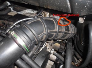
10.Turbo (Inlet)
Remove the pipe from the air resovoire to the turbo inlet. Its a bit awkward to get at the turbo side, but do this and ensure the pipe is clean. It is also linked to the crankcase breather, so ensure there isn’t gunk there.
Test
Once the pipe is removed you can actually stick a finger in the turbo and touch the compressor rotor. Spin this manually and ensure it spins easily and freely, and ensure there is no play in/out or side/side if there is, then you have a turbo issues of some sort. It should not move much beyond rotating freely.
Once that is clear, reassemble and I would suggest removing a “Boost pipe”, maybe the first one (from turbo to intercooler) as its easy to get to. Then start the engine, and at 2000rpm air should be blown out. If no air is blown out at all, then your turbo isn’t working or the pipes are blocked.
See sections on boost pipe & VNT actuator for futher tests.
11.Turbo boost pipes
Post turbo, the pipes will be (or should be) under pressure when the engine is being revved or driven. As such the pipes will be under pressure and leaks may become apparent. The problem is, at idle, there isn’t always enough pressure to show leaks.
I took off and manually checked every pipe from the turbo to the inlet manifold. There are rubber pipes to inspect for signs of wear on joins, or splits, or any form of damage. There is also the EGR pipe which is metal where someone on the internet has had a pipe split and needed it welding. So check everything.
Pipes are fairly easy to get off with the exeption of the ones connected to the turbo boost outlet! There, there is a short flexible bit of rubber, linked to a plastic thingie, then to a rubber pipe. All mine were in perfect condition but it was easy to see how pipes could split and not be evident from a visual test.
Any leak would give lack of power, so check carefully, and reassemble well!
12.Inlet Manifold
The inlet manifold sits under a few bits, so see HERE for instructions on how to remove it. This is worth checking as if you haven’t blocked your EGR valve, all the exhaust crap will be going into the inlet manifold and blocking it up. I’ve seen pictures with 30% gunk! Mine (with blank EGR) was 99.9% clear 🙂
But worth taking off, checking and cleaning.
Also, inspect for damage and cracks, again someone on the internet has had a cracked inlet manifold which would vastly reduce boost pressure. Definately inspect carefully.
13.Intercooler
Bearing in mind the turbo pipework is connected to the crank breather pipe, and the EGR is linked, then any gunk/oil in the air will accumalate in the lowest possible point – which is the intercooler. Many people have blocked intercoolers which will restrict the flow of air and thus boost pressure.
Test
I would take off the in/out boost pipes of the intercooler, and clean up one of the sides. Then simply blow through it. You should get fairly free-flowing and unrestricted air going through. If it is excessively dirty or restricted then you will need to clean it out or use a new intercooler. (You can’t bypass the intercooler as the MAP sensor would then not get a boost reading and you would cause a boost error DTC!
14.EGR
The EGR is a valve that sends dirty exhaust gasses back into the engine for a second burning. This is entirely for emisssions control, but the side effect is all the crap in the exhaust goes back through the valve, back into the inlet manifold and makes a mess.
On the Mk6 van the EGR is vacuum operated and does NOT have any sensor on it – so this means you can block it and stop it sending the dirt into the engine! This means the engine gets cleaner air and there are no side effects.
On my van, the EGR failed (due to getting covered in soot) which is common, so I disabled it. See HERE for detaild of EGR fixing.
15.Vacuum pump
The vaccum pump is bolted to the engine, and how it works is beyond this scope. However, what it does, is provide a constant vacuum to the devices that need it – namely the brakes and the VNT/EGR solenoids.
All we care about here, is to ensure there is enough vaccum being sent to the VNT/EGR solenoids.
Test
There are 3 vacuum pipes that run across the engine next to the oil filler – one goes to EGR, one goes to VNT, and one goes up to the top of the engine, then left towards the brake servo. This is the one we want to test as it is this that provides the vacuum needed to operate the turbo.
Locate this pipe and pull it apart on the 90′ elbow.
With engine off, using the
– test the pipe in both directions, ensure the vacuum holds. (if not, check pipes)
With engine running, connect to the side of the pipe connecting towards the vacuum pump – and this should suck > 70 kpa and be constant. Any less, check pipes and ensure vacuum pump is OK
16.VNT Actuator
The VNT actuator is basically a vacuum operated lever which controls the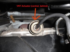
Testing
- With engine not hot, feel behind where the arrow is and find the actuator. This feels like an old throttle cable type setup.
- With engine off, the actuator should be relaxed (back), and you should be able to pull it forward with one finger. Let go, it should spring back. If not, your VNT is probablu crudded up with carbon and will need clearning.
- Assuming it is smooth and moves freely, continue tests….
The way it should work is:-
- On engine off, relaxed
- On ide, pulled in
- On revving from idle to 3000rpm fairly gentle, the lever show go back slowly
If so, it is behaving
If not check:-
- Using – connect to actuator and apply 65kpa vacuum. Whilst applying and increasing vacuum, the actuator should be pulled in smoothly and fully at 65kpa. When vacuum released slowly, lever should move back.
- Actuator should move at least 10mm between “on” and “relaxed”
- When vacuum applied to actuator, it should remain. If it leaks you’ve got a broken vacuum diaphragm.
To check to ensure the VNT is moving, remove the 90′ intercooler elbow and start the engine.
- On idle, with vacuum off (and turbo relaxed) there will be only a very very small blow
- On idle, with vacuum on (and turbo in) there will be a gentle blow
If this is the case, turbo is working!
17.VNT Vacuum pipework
If the turbo is working by manually applying vacuum but not always automatically, check the pipework. Trace the VNT vacuum pipe back back to the solenoid, and it should be connected on the top (see next section). Disconnect from solenoid and apply vacuum to that pipe. 65kpa should move the actuator fully and the vacuum should hold. If not, you have a leak.
Note – my issue was someone swapped the VNT pipe to the EGR pipe on the 90′ elbow to the right of the oil filler – so check carefully that it goes back to the correct solenoid.
18.VNT Solenoid

It has an input from the vacuum pump, and outlet to the air filter which are shared between the EGR and VNT solenoids. And the top solenoid (green plug) controls the VNT actuator the bottom solenoid (black plug) controlls the EGR.
Testing
- With engine running, unplug the pipe coming from the vacuum pump – check you get >70kpa vacuum
- With engine running, check that at least 65kpa is being sucked in on the VNT pipe
- Check the green plug is in correctly, and when engine idling, it has 12-14v on one pin, and 10+v on the other pin. (between pin and earth).
In my tests, on idle, the green plug is powered and vacuum is demanded and actuates the VNT; then unplug the green plug and vacuum is released and turbo relaxed. Ensure the green plug/top pipe is to VNT!!!!!
19.ECU Reset
Last resort that did nothing for me, but as the ECU “learns” how the vehicle behaves it tunes itself accordingly. Disconnecting battery for 48 hours resets all these parameters…. As I said, last resort….
20.Cat/Exhaust
It was mentioned that blocked/failed CAT or exhaust could restrict air flow out, so something worth considering if you feel this is the case. I “tapped” the entire length to see if anything sounded solid, but beyond that I assumed it was OK. To be fair, it “felt” and “sounded” okay. But, cats fail and block the exhaust so don’t rule it out.
Do note, TDCi VNT engines do not like being de-catted! TDDi engines are, apparently, ok, but don’t do it on a TDCi without research!
Давление ниже нижнего предела
Наличие ошибки P0235 при компьютерной диагностики автомобиля гласит о том, что присутствует недодув (недостаточное насыщение топлива воздухом)! Информация считывается с датчика давления наддува «А». Тут все сложнее чем с ошибкой Р0234.
И опять все по порядку!
- Первая причина, по которой может возникать ошибка Р0235, это неисправность самого датчика. Причины его неисправности могут быть разные, от загрязнения, до банального естественного старения, как и в прошлом случае. Данная проблема решается заменой датчик на новый. Опять не рекомендуем менять на не оригинальный- китайского производства, т.к. возможно, что проблема не уйдет.
- Неисправность клапана управления турбиной.
- Заклинивание исполнительного механизма управления наддувом в турбокомпрессоре.
- Неисправность электромагнитного клапана
- Заклинивание механизма изменяемой геометрии соплового аппарата турбокомпрессора.
Пункты 2-5 описаны в статье «Ошибка P0234».
- Неисправность системы рециркуляции выхлопных газов (EGR)
В данном случае ошибка Р0235- недонаддув, возникает по причине не корректной работы системы EGR. Клапан постоянно находится в открытом положении. В результате чего происходит цикличное использование выхлопных газов, как-бы в обход ротора колеса турбины, что приводит к недостаточной скорости потока выхлопных газов и как следствие- невозможности разогнать ротор турбины до необходимых оборотов.
Данная проблема решается заменой, ремонтом, либо отключением системы рециркуляции выхлопных газов, при необходимости, с перепрошивкой программного обеспечения автомобиля.
Неисправность самого механизма (EGR) характеризуется наличием ошибки Р0401. Поэтому зачастую эти две ошибки появляются одновременно в случае неисправности данной системы, при условии = клапан открыт.
- Забитый сажевый фильтр, катализатор.
Ошибка Р0235 может возникнуть и при забитом сажевом фильтре и катализаторе.
Это происходит потому, что уменьшается пропускная способность данных узлов и как следствие уменьшается скорость потока выхлопных газов, которые в свою очередь не разгоняют должным образом ротор турбины, а она не создает должный наддув, что и приводит к нехватке воздуха в системе!
Как правило забитый катализатор и сажевый фильтр на большинстве автомобилей можно диагностировать только визуально и по косвенным признакам. Поэтому данного рода проблема часто остается незамеченной.
Проблема решается заменой, либо удалением данных узлов с последующей, перепрошивкой программного обеспечения, на автомобилях где это необходимо.
- Не герметичность воздуховодов.
В данном случае все понятно! Где-то есть дырка и турбокомпрессор дует в космос, а не в камеру сгорания.
- Не герметичность вакуумной системы управления турбиной
Не герметичность вакуумной системы управления турбиной при условии наличия данной системы, приводит к невозможности регулировать наддув посредством изменения давления в самой системе, что и приводит к недонаддуву.
- Механическая неисправность турбины.
На данном разделе мы не будем останавливаться. Всю необходимую информацию по данному вопросу можно получить тут- https://www.turbolider.ru/articles/prichinyi-vyihoda-iz-stroya-turbokompressora-turbinyi-povrezhdeniya-detaley-tkra/
Дмитриев Р.Д.
ООО «Мастертурбо» 2020г.


