Introduction
This document describes soft and hard parity errors, explains common error messages, and recommends methods that help you avoid or minimize parity errors. Recent improvements in hardware and software design reduce parity problems as well.
Background
What is a processor or memory parity error?
Parity checking is the storage of an extra binary digit (bit) in order to represent the parity (odd or even) of a small amount of computer data (typically one byte) while that data is stored in memory. The parity value calculated from the stored data is then compared to the final parity value. If these two values differ, this indicates a data error, and at least one bit must have been changed due to data corruption.
Within a computer system, electrical or magnetic interference from internal or external causes can cause a single bit of memory to spontaneously flip to the opposite state. This event makes the original data bits invalid and is known as a parity error.
Such memory errors, if undetected, may have undetectable and inconsequential results or may cause permanent corruption of stored data or a machine crash.
There are many causes of memory parity errors, which are classified as either soft parity errors or hard parity errors.
Soft Errors
Most parity errors are caused by electrostatic or magnetic-related environmental conditions.
The majority of single-event errors in memory chips are caused by background radiation (such as neutrons from cosmic rays), electromagnetic interference (EMI), or electrostatic discharge (ESD). These events may randomly change the electrical state of one or more memory cells or may interfere with the circuitry used to read and write memory cells.
Known as soft parity errors, these events are typically transient or random and usually occur once. Soft errors can be minor or severe:
- Minor soft errors that can be corrected without component reset are single event upsets (SEUs).
- Severe soft errors that require a component or system reset are single event latchups (SELs).
Soft errors are not caused by hardware malfunction; they are transient and infrequent, are mostly likely a SEU, and are caused by an environmental disruption of the memory data.
If you encounter soft parity errors, analyze recent environmental changes that have occurred at the location of the affected system. Common sources of ESD and EMI that may cause soft parity errors include:
- Power cables and supplies
- Power distribution units
- Universal power supplies
- Lighting systems
- Power generators
- Nuclear facilities (radiation)
- Solar flares (radiation)
Hard Errors
Other parity errors are caused by a physical malfunction of the memory hardware or by the circuitry used to read and write memory cells.
Hardware manufacturers take extensive measures to prevent and test for hardware defects. However, defects are still possible; for example, if any of the memory cells used to store data bits are malformed, they may be unable to hold a charge or may be more vulnerable to environmental conditions.
Similarly, while the memory itself may be operating normally, any physical or electrical damage to the circuitry used to read and write memory cells may also cause data bits to be changed during transfer, which results in a parity error.
Known as hard parity errors, these events are typically very frequent and repeated and occur whenever the affected memory or circuitry is used. The exact frequency depends on the extent of the malfunction and how frequently the damaged equipment is used.
Remember that hard parity errors are the result of a hardware malfunction and reoccur whenever the affected component is used.
If you encounter hard parity errors, analyze physical changes that have occurred at the location of the affected system. Common sources of hardware malfunction that may lead to hard parity errors include:
- Power surges (no ground)
- ESD
- Overheating or cooling
- Incorrect or partial installation
- Component incompatibility
- Manufacturing defect
Common Error Messages
The Cisco IOS® software provides a variety of parity error messages, which vary with the affected component and its relative impact on the system.
Processor
|
Cache error detected! Real cache error detected. System will be halted. Error: Primary instr cache, fields: data, Imprecise Data Parity Error |
|
| Explanation | This is the result of a parity error within the Level 2 (L2) cache (static random-access memory, or SRAM) used by route processor (RP) or switch processor (SP) CPU of the Multilayer Switch Feature Card 3 (MSFC3). |
| Recommendation | Monitor the system regularly for reoccurrence. If no further events are observed, it is a soft error. If the error occurs frequently, request a Return Material Authorization (RMA) in order to replace the Supervisor Engine, and mark the module for equipment failure analysis (EFA). |
| %SYSTEM_CONTROLLER-3-ERROR: Error condition detected: SYSAD_PARITY_ERROR | |
| Explanation | This is the result of a parity error in the system address (data bus) used by the In-Band Controller (IBC) of the MSFC3. |
| Recommendation | Monitor the system regularly for reoccurrence. If no further events are observed, it is a soft error. If the error occurs frequently, request an RMA in order to replace the Supervisor Engine, and mark the module for EFA. |
| %SYSTEM_CONTROLLER-3-ERROR: Error condition detected: TM_DATA_PARITY_ERROR | |
| Explanation | This is the result of a parity error in the table manager data used by the IBC of the MSFC3. |
| Recommendation | Monitor the system regularly for reoccurrence. If no further events are observed, it is a soft error. If the error occurs frequently, request an RMA in order to replace the Supervisor Engine, and mark the module for EFA. |
| %SYSTEM_CONTROLLER-3-ERROR: Error condition detected: TM_NPP_PARITY_ERROR | |
| Explanation | This is the result of a parity error in the table manager ‘next page pointer’ used by the IBC of the MSFC3. |
| Recommendation |
Monitor the system regularly for reoccurrence. If no further events are observed, it is a soft error. If the error occurs frequently, request an RMA in order to replace the Supervisor Engine, and mark the module for EFA. In Cisco IOS software versions between 12.1(8)E and 12.2(33)SXI3, the default behavior in response to SYSTEM_CONTROLLER-3-ERROR events was to reset the IBC and log an error message. However, this corrective action resulted in some documented cases of the IBC (and thus, CPU) no longer being able to transmit or receive data. Thus, the behavior was changed in Cisco IOS software versions later than 12.2(33)SXI4 to log an error message and reset the system; refer to Cisco bug ID CSCtf51541. |
| Interrupt exception, CPU signal 20, PC = 0x[dec] | |
| Explanation | This is the result of a single-bit parity error in the CPU L2 cache (SRAM) used by the Cisco Catalyst 6700 Series modules. |
| Recommendation |
Monitor the system regularly for reoccurrence. If no further events are observed, it is a soft error. If the error occurs frequently, request an RMA in order to replace the 6700 module, and mark the module for EFA. In Cisco IOS software versions earlier than 12.2(33)SXI5, a software bug (Cisco bug ID CSCtj06411) would cause even single-bit parity errors to reset the 6700 module. This was resolved in Versions 12.2(33)SXI6 and 12.2(33)SXJ for Supervisor Engine 720 and in Version 15.0SY for Supervisor Engine 2T. |
RAM
| %SYSTEM_CONTROLLER-3-ERROR: Error condition detected: SYSDRAM_PARITY_ERROR | |
| Explanation | This is the result of an uncorrectable parity error in the synchronous DRAM (SDRAM) memory modules (DIMM) used by the MSFC3. |
| Recommendation | Monitor the system regularly for reoccurrence. If no further events are observed, it is a soft error. If the error occurs frequently, clean and reseat the DIMM, and continue to monitor. If the error continues, request an RMA in order to replace or upgrade the DIMM. |
| %SYSTEM_CONTROLLER-3-COR_MEM_ERR: Correctable DRAM memory error. Count [dec], log [hex] | |
| Explanation | This is the result of a correctable parity error in the SDRAM (DIMM) used by the MSFC3. |
| Recommendation | Monitor the system regularly for reoccurrence. If no further events are observed, it is a soft error. If the error occurs frequently, clean and reseat the DIMM, and continue to monitor. If the error continues, request an RMA in order to replace or upgrade the DIMM. |
| %MWAM-DFC[dec]-0-CORRECTABLE_ECC_ERR: A correctable ECC error has occurred, A_BUS_L2_ERRORS: 0x10000, A_BUS_MEMIO_ERRORS: 0x0, A_SCD_BUS_ERR_STATUS: 0x80983000 | |
| Explanation |
This is the result of a single-bit parity error in the DRAM used by 6700 Series modules. |
| Recommendation |
Monitor the system regularly for reoccurrence. If no further events are observed, it is a soft error. If the error occurs frequently, clean and reseat the DIMM, and continue to monitor. If the error continues, request an RMA in order to replace or upgrade the DIMM. |
| %PM_SCP-SP-2-LCP_FW_ERR_INFORM: Module [dec] is experiencing the following error: LTL Parity error detected on Coil #[dec]. | |
| Explanation | This is the result of a parity error in the SRAM used by the Cisco Catalyst 6100 and Cisco Catalyst 6300 Series modules. |
| Recommendation |
Monitor the system regularly for reoccurrence. If no further events are observed, it is a soft error. If the error occurs frequently, request an RMA in order to replace the 6100 or 6300 module, and mark the module for EFA. |
| %SYS-4-SYS_LCPERR4: Module [dec]: LTL Parity error detected on Coil #[dec] | |
| Explanation | This is the result of a parity error in the SRAM used by the 6100 and 6300 Series modules. |
| Recommendation | Monitor the system regularly for reoccurrence. If no further events are observed, it is a soft error. If the error occurs frequently, request an RMA in order to replace the 6100 or 6300 module, and mark the module for EFA. |
ASIC
| %PM_SCP-SP-2-LCP_FW_ERR_INFORM: Module [dec] is experiencing the following error: Port ASIC ([name]) packet buffer failure detected on ports [dec] | |
| Explanation | This is the result of a parity error in the port ASIC packet buffer (SRAM) used by the Cisco Catalyst 6148A Series Ethernet modules. |
| Recommendation |
Monitor the system regularly for reoccurrence. If no further events are observed, it is a soft error. If the error occurs frequently, request an RMA in order to replace the 6148A module, and mark the module for EFA. |
| %LTL-SP-2-LTL_PARITY_CHECK: LTL parity check request for 0x[hex] | |
| Explanation | This is the result of a parity error in the port ASIC port index table (SRAM) used by the Catalyst 6100-6500 and 6700 Series modules. |
| Recommendation | Monitor the system regularly for reoccurrence. If no further events are observed, it is a soft error. If the error occurs frequently, request an RMA in order to replace the module, and mark the module for EFA. |
Refer to these Cisco IOS software documents for a comprehensive list of error messages:
- Cisco IOS Release 12.2SX System Message Guide
- Cisco IOS Release 15.x SY System Message Guide
The Output Interpreter Tool (registered customers only) supports certain show commands. Use the Output Interpreter Tool in order to view an analysis of show command output.
Latest Advancements
Research into the field of parity errors is ongoing, and not every scenario can be addressed, but the Cisco Catalyst 6500 hardware and software development organizations continue to introduce new ways, such as error-correcting code (ECC) protection, to minimize and mitigate the occurrence of parity errors.
While this document began with discussion of the third generation (WS-XSUP720 and early 6700 Series) of Catalyst 6500 products, this section summarizes improvements introduced with the fourth generation (VS-S720-10G and later 6700 Series) and the fifth generation (VS-SUP2T-10G and 6900 Series).
Processor
The VS-S720-10G module features a newer MSFC3 daughterboard, with a new IBC and updated SR7010A reduced instruction set computing (RISC) RP and SP CPUs that operate at 600Mhz each. The Level 1 (L1), L2, and Level 3 (L3) caches are capable of parity detection. The newer IBC has all of the functionality of the earlier generation and adds ECC protection (single-bit correction, multi-bit detection) to the attached SRAMs.
The 6700 Series modules support a CPU with ECC-protected L2 cache (L1 cache is parity detection capable), which can correct single-bit parity errors without the need to reset. However, due to Cisco bug ID CSCsz39222, Version 12.2SXI of the Cisco IOS software (Supervisor Engine 720) resets the module anyway if a single-bit CPU cache parity error occurs. This is resolved in Versions 12.2SXJ (Supervisor Engine 720) and 15.0SY (Supervisor Engine 2T) of the Cisco IOS software.
The VS-SUP2T-10G features a new MSFC5 daughterboard with an integrated IBC and a new single, dual-core MPC8572 PPC RP CPU (with ECC-protected L2 and L3 cache, L1 cache is parity detection capable) that operates at 1.5Ghz per core. It also features a new, separate, out-of-band Connectivity Management Processor (CMP) CPU and ECC-protected DRAM, which is available even if the RP CPU is currently unavailable.
The new IBC has all of the functionality of earlier generations and supports ECC protection for the attached SRAMs and improvements in parity error handling. The new MSFC5 also features an Onboard Failure Logging (OBFL) ROM, which stores all module initialization and diagnostics events. The new single CPU design also reduces the statistical likelihood of parity error events.
The 6900 Series modules support a newer CPU with ECC-protected L1 and L2 cache, which can correct single-bit parity errors without the need to reset. The new generation supports the same IBC, and the software handling for single-bit parity error correction has been incorporated.
RAM
The VS-S720-10G with MSFC3 features double-data-rate (DDR) SDRAM with ECC protection, operating at 266Mhz.
The 6700 Series modules support DDR SDRAM with ECC protection, operating at 266Mhz.
Compared to single-data-rate (SDR) SDRAM, the DDR SDRAM interface makes higher transfer rates possible by more strict control of the timing of the electrical data and clock signals. The DDR interface uses double pumping (data transfer on both the rising and falling edges of the clock signal) in order to lower the clock frequency. Lower clock frequency reduces the signal integrity requirements on the circuit board that connects the memory to the controller.
The VS-SUP2T-10G with MSFC5 features DDR3 SDRAM with ECC protection, operating at 667Mhz.
The 6900 Series modules support DDR3 SDRAM with ECC protection, operating at 667Mhz.
The primary benefit of DDR3 SDRAM over its immediate predecessors (DDR2 and DDR) is its ability to transfer data at twice the rate (eight times the speed of its internal memory arrays), which enables higher bandwidth or peak data rates. DDR3 memory also reduces power consumption by 30%, even though it uses the same electric signaling standard as DDR and DDR2.
ASIC
The VS-S720-10G with PFC3C features SRAM packet buffers with ECC protection. This provides single-bit parity error correction without module reset, as well as multi-bit parity error detection.
The 6700 Series with DFC3C features SRAM packet buffers with ECC protection. This provides single-bit parity error correction without module reset, as well as multi-bit parity error detection.
The VS-SUP2T-10G with PFC4 features SRAM packet buffers with ECC protection. This provides single-bit parity error correction without module reset, as well as multi-bit parity error detection.
The 6900 Series with DFC4 features SRAM packet buffers with ECC protection. This provides single-bit parity error correction without module reset, as well as multi-bit parity error detection.
Software
The Cisco IOS software is designed to support ECC protection. If a hardware component that supports ECC protection experiences an SEU, the code should correct the corrupt data or reset the affected component and not require a full hardware reset of the affected module.
However, in earlier versions of Cisco IOS software, there are a few exceptions where the behavior has been intentionally changed or malfunctions due to a software bug. Here are two notable exceptions.
MSFC IBC Reset
In Cisco IOS software versions between 12.1(8)E and 12.2(33)SXI3, the default behavior in response to SEU SYSTEM_CONTROLLER-3-ERROR events was to reset the IBC and log an error message. However, this corrective action resulted in some documented cases of the IBC (and thus, CPU) no longer being able to transmit or receive data.
Thus, the behavior was changed after Version 12.2(33)SXI4 (Cisco bug ID CSCtf51541) to log an error message and reset the system. While this reaction may seem more severe, it is preferable to reset the system and correct the memory structure than to have an unresponsive system.
A feature now in development (Cisco bug ID CSCtr89859) will add a new command-line interface (CLI) command that lets you switch the default behavior. This enhancement is most applicable to systems that use a single supervisor and thus have no supervisor redundancy.
6700 Series ‘Single-Bit Parity Error’ Reset
In Cisco IOS software versions earlier than12.2(33)SXI5, a software bug (Cisco bug ID CSCtj06411) would cause even single-bit parity errors to reset the 6700 module. This would normally be a correctable parity error and not require the module to be reset.
This bug was resolved in Versions 12.2(33)SXI6+ and 12.2SXJ for Supervisor Engine 720 and in Version 15.0SY for Supervisor Engine 2T. After an upgrade to the appropriate version, the 6700 module simply logs an error message and continues to operate.
Recommendations
By this point, you have probably determined whether you have encountered a soft or hard parity error. While this may address a single incident, other parity error vulnerabilities may still exist, so you should take a more comprehensive approach to your entire network.
Thus, Cisco and the Catalyst 6500 business unit recommend that you review these mitigation procedures and take appropriate corrective actions in order to eliminate or reduce future parity errors.
Soft Errors (SEU)
Single event (soft) parity errors are caused by environmental conditions and may occur only once (SEU) or very infrequently, such as monthly or yearly. Although you do not need to replace the hardware, you do want to mitigate future occurrences.
These best practices significantly reduce the likelihood of soft parity errors.
Environmental Audit
Cisco recommends that you perform an environmental audit of your affected network locations. You may perform this audit yourself or in coordination with a Cisco representative, with a Cisco team (such as Cisco Advanced Services), or through a third-party consultant.
The exact coverage and complexity of an environmental audit depend on many different variables such as geographic location, building and room size and design, electrical design and layout, and other related factors.
Consider what environmental sources of ESD and EMI may exist in or around your network. These are common sources of interference that may lead to a soft parity error:
- Power cables and supplies
- Power distribution units
- Universal power supplies
- Lighting systems
- Power generators
- Nuclear facilities (radiation)
- Solar flares (radiation)
Chassis Placement
SEUs can occur if power distribution units, power generators, or lighting systems are too close to the chassis or if multiple power cables are on or beside the chassis.
It is important to provide adequate distance between the Catalyst 6500 chassis and these electrical and magnetic sources. Recommended distances vary by component and are available from the component datasheets.
In general, Cisco recommends you locate systems at least three to six inches from common sources of electrical and magnetic interference. Power cables should be routed down and away from the chassis, wherever possible, and should not be laid in tightly packed bundles or in large numbers across or beside the chassis.
Grounding
Power fluctuations and power surges are relatively common, and Catalyst 6500 power supplies are designed to accommodate minor variations in voltage current.
However, it is critical to provide proper electrical grounding for the chassis and rack so any excess electrical voltage is drawn away from the system. Without proper grounding, power surges may result in damage or malfunction in various ASICs and memory components. Refer to the Catalyst 6500 Series Switch Installation Guide, Installing the Switch, Establishing the System Ground, for more information.
ESD
ESD can easily damage critical components without any visible impairment. Appropriate preventive measures should be incorporated into lab operation policies, but such measures are often and unfortunately ignored due to expedience and limited oversight.
Cisco recommends that your lab operations management, along with Cisco Systems, perform an environmental audit of all network areas or, at a minimum, of all areas that have exhibited hardware failures or have been designated as mission critical. Once the audit is complete, Cisco recommends that you implement a standardized environmental checklist for all newly installed systems in order to avoid future SEU parity events.
Latest Firmware (Rommon)
Catalyst hardware components use firmware (also known as Rommon) code to initialize, communicate, and run diagnostics. Once these functions are complete, system operation is turned over to the Cisco IOS software. It is uncommon to experience issues with firmware, but there can be issues if you use different versions of firmware code for the Supervisors and the modules.
Thus, it is a best practice to ensure that all components use the latest firmware code in order to ensure proper module initialization and communication. Cisco recommends that your operations management perform a network audit and upgrade all hardware components with the latest firmware version.
Known firmware issues and upgrade procedures are documented in:
- Release Notes for Supervisor Engine 720 Switch Processor ROMMON
- Release Notes for 6700 Series Switching Module ROMMON
Download the latest firmware versions from the Cisco web site:
- Cisco Catalyst 6500 Series Supervisor Engine 720 / MSFC3 – 8.5(4) Rommon
- Cisco Catalyst 6500 Series Virtual Switching Supervisor Engine 720 with 10GE Uplinks — 12.2(18r)S1 Rommon
Thumb Screws
All modular networking systems are designed to insert into a chassis backplane with a set of physical interface pins. The chassis backplane itself is essentially a series of interconnected wires. The pins in each chassis slot form the physical data connection between the Supervisor and Ethernet modules. Thus, proper insertion and alignment of these pins is critical.
The Catalyst 6500 provides guide rails and alignment pins that assist in the installation in the chassis. The slot pins (sockets) and module connectors are designed to easily engage and provide high-bandwidth capable electrical connectivity. Once inserted into the chassis, there are thumb screws on either side of the module that fully engage the backplane pins. Refer to the Catalyst 6500 Series Switch Module Installation Note.
If a module has been properly inserted into the slot and the thumb screws have been correctly tightened, no communication problems are expected. However, several conditions may occur in day-to-day insertion of modules that can lead to improper or even incomplete pin insertion:
- Insufficient insertion force — If the module is partially inserted without use of the thumb screws, this may cause bus stalls, and the module may not be able to communicate with other modules. Depending on the level of insertion (for example, if there is limited physical contact), the module may be able to transmit and receive data, but may experience bit errors that result in corrupt packets.
- Vertical misalignment — This occurs when only one side of the module is on the guide rails. This is easily identified because the module appears diagonal and does not usually connect with the backplane pins.
- Horizontal misalignment — If thumb screws are used on only one side, some of the pins do not engage properly. This is a common problem, because the module may appear to be properly inserted. Horizontal misalignment is actually a form of insufficient insertion force.
Cisco recommends that you implement an operation management process that mandates the use of the thumb screws on all Catalyst 6500 modules in production environments. This ensures proper and full insertion and alignment of backplane pins and prevents future failures due to bit errors and related communication failures.
Hard Errors (Malfunction)
Frequent or repeatable (hard) parity errors are caused by physical malfunction of the memory or the circuitry used to read and write. In such cases, replace the hardware and ask the Cisco Technical Assistance Center (TAC) or your Cisco Systems Engineer to conduct an EFA on the returned hardware.
These best practices significantly reduce the likelihood of hard parity errors.
Hardware (MTBF and EOL) Audit
Cisco recommends that you perform a network audit of your affected network locations. You may perform this audit yourself or in coordination with a Cisco representative, with a Cisco team (such as Cisco Advanced Services), or through a third-party consultant.
All hardware (from all vendors) is subject to eventual degradation of physical integrity, and it is important to track the life cycle of all hardware components in your network in order to fully understand the likelihood of component failure over time.
Hardware reliability can be measured with the mean time between failure (MTBF) framework. Since MTBF is only a statistical average, this does not mean that a failure will definitely occur at the end of the MTBF time period. However, the likelihood and vulnerability of component failure increases, so such hardware should be flagged for refresh. Refer to the Cisco Catalyst 6500 Series Switches Data Sheets for specific MTBF values for each Catalyst 6500 product.
The aggregated calculated Catalyst 6500 ‘system-level’ MTBF value is > 7 years.
In addition to the MTBF framework, Cisco also provides an end-of-life (EOL) framework, which defines the expected life cycle of a given product and provides applicable announcements in order to help you refresh your legacy equipment. Refer to the End-of-Life and End-of-Sale Notices for various legacy Catalyst 6500 products.
As a result of this hardware audit, Cisco recommends that you implement your own MTBF and EOL process that identifies and tracks hardware for potential refresh. This ensures that the latest hardware is running and minimizes the likelihood of hardware malfunction.
Hardware Diagnostics
The Catalyst 6500 Series and Cisco IOS software provides Generic Online Diagnostics (GOLD) and Health Monitoring (HM) diagnostics for all hardware components used in the system. The two basic types of diagnostics that can be enabled are on-demand and boot-up. Refer to Generic Online Diagnostics on the Cisco Catalyst 6500 Series Switch for additional information.
Cisco recommends that ‘complete’ boot-up diagnostics be enabled for all hardware components in order to ensure that all diagnostic tests are executed and to confirm that all hardware components are functioning as expected upon boot-up.
Cisco also recommends that you schedule regular, on-demand diagnostics of critical infrastructure components on a daily or weekly basis. Beyond the boot-up diagnostics that occur only during initialization, the on-demand diagnostics ensure that the hardware continues to operate as expected. Refer to Catalyst 6500 Release 12.2SX Software Configuration Guide, Interface and Hardware Components, Online Diagnostics for more information.
In addition to the default on-demand diagnostic tests, Cisco recommends that you enable these on-demand diagnostic tests in order to proactively identify memory components that might malfunction:
- TestLinecardMemory
- TestAsicMemory
Related Information
- Cisco Community — %C4K_RKNOVA-2-EDACSOFTERROR
- Technical Support & Documentation — Cisco Systems
Introduction
This document explains what causes parity errors on Cisco routers, and how to troubleshoot them.
Prerequisites
Requirements
Cisco recommends that you have knowledge of how to troubleshoot router crashes.
Refer to Troubleshooting Router Crashes for more information.
Components Used
This document is not restricted to specific software and hardware versions.
The information in this document was created from the devices in a specific lab environment. All of the devices used in this document started with a cleared (default) configuration. If your network is live, make sure that you understand the potential impact of any command.
Conventions
Refer to Cisco Technical Tips Conventions for more information on document conventions.
Identify a Parity Error
Memory parity errors occur in MultiChannel Interface Processor (MIPS)-based processor products such as:
-
Cisco 4500/4700 Series Routers
-
Cisco 7500 Series Routers (RSP1, RSP2, RSP4, RSP8, VIP2-10, VIP2-15, VIP2-20, VIP2-40, VIP2-50)
-
Cisco 7000 Series Routers (RSP 7000)
-
Cisco 7200 Series Routers (NPE-100, NPE-150, NPE-175, NPE-200, NPE-225, NPE-300)
-
Cisco 12000 Series Internet Router
Here are some messages, which are all related to the detection of bad parity somewhere in the system (the list is not exhaustive, but contains the most common messages):
-
In the show version command output:
System restarted by processor memory parity error at PC 0x6014F7C0,
 address 0x0
or
System restarted by shared memory parity error at PC 0x60130F40
If you have the output of a show version command from your Cisco device, you can use Cisco CLI Analyzer to display potential issues and fixes. In order to use Cisco CLI Analyzer, you must be a registered customer, be logged in, and have JavaScript enabled.
-
In the console logs, or in the crashinfo files:
-  *** Cache Error Exception ***
   Cache Err Reg = 0xa401a65a
   data reference, primary cache, data field error , error on SysAD Bus
   PC = 0xbfc17950, Cause = 0x0, Status Reg = 0x3040d007


-  Error: primary data cache, fields: data,
   virtual addr 0x6058A000, physical addr(21:3) 0x18A000, vAddr(14:12) 0x2000
   virtual address corresponds to main:data, cache word 0

                Low Data   High Data  Par    Low Data   High Data  Par
   L1 Data  : 0:0xFEFFFEFE 0x65776179 0x13 1:0x20536572 0x76657220 0x89
              2:0x646F6573 0x206E6F74 0x9C 3:0x20737570 0x706F7274 0xF8

                Low Data   High Data  Par    Low Data   High Data  Par
   Mem Data : 0:0xFEFFFEFE 0x65776179 0x13 1:0x20536572 0x76657220 0x89
              2:0x646F6573 0x206E6F74 0x9C 3:0x20737570 0x706F7274 0xF8


-  *** Shared Memory Parity Error ***
   shared memory control register= 0xffe3
   error(s) reported for: CPU on byte(s): 0/1

-  %PAR-1-FATAL: Shared memory parity error
   shared memory status register= 0xFFEF
   error(s) reported for: CPU on byte(s): 0/1 2/3


-  %RSP-3-ERROR: MD error 0000008000000200
   %RSP-3-ERROR: QA parity error (bytes 0:3) 02
   %RSP-3-ERROR: MEMD parity error condition
   %RSP-2-QAERROR: reused or zero link error, write at addr 0100 (QA)
       log 22010000, data 00000000 00000000
   %RSP-3-RESTART: cbus complex


-  %RSP-3-ERROR: CyBus error 01
   %RSP-3-ERROR: read data parity
   %RSP-3-ERROR: read parity error (bytes 0:7) 20
   %RSP-3-ERROR: physical address (bits 20:15) 000000

-  %RSP-3-ERROR: MD error 00800080C000C000
   %RSP-3-ERROR: SRAM parity error (bytes 0:7) F0
   %RSP-3-RESTART: cbus complex
Soft Versus Hard Parity Errors
There are two kinds of parity errors:
-
Soft parity errors
These errors occur when an energy level within the chip (for example, a one or a zero) changes. When referenced by the CPU, such errors cause the system to either crash (if the error is in an area that is not recoverable) or they recover other systems (for example, a CyBus complex restarts if the error was in the packet memory (MEMD)). In case of a soft parity error, there is no need to swap the board or any of the components. See the Related Information section for additional information about soft parity errors.
-
Hard parity errors
These errors occur when there is a chip or board failure that corrupts data. In this case, you need to re-seat or replace the affected component, which usually involves a memory chip swap or a board swap. There is a hard parity error when multiple parity errors occur at the same address. There are more complicated cases that are harder to identify. In general, if you see more than one parity error in a particular memory region in a relatively short period, you can consider it to be a hard parity error.
Studies have shown that soft parity errors are 10 to 100 times more frequent than hard parity errors. Therefore, Cisco highly recommends you to wait for a second parity error before you replace anything. This greatly reduces the impact on your network.
Isolate the Problem
A router has memory in different locations. Theoretically, any memory location can be affected by the parity error, but most memory problems occur in dynamic RAM (DRAM) or shared RAM (SRAM). Based on the platform, here is how you can find out what memory location has been affected, and, if it turns out to be a hard parity error, what part you must replace:
Cisco 4500 and 4700 Platforms
On the Cisco 4500 and 4700 platforms, the crashinfo file is not available in versions earlier than Cisco IOS® Software Release 12.2(10) and 12.2(10)T.
One way to find out where the error occurred is to look at the «restart reason» in the console logs, and in the output of the show version command:
-
Parity Error in DRAM:
If you did not manually reload the router after the crash, the show version output looks like this:
System restarted by processor memory parity error at PC 0x601799C4,
 address 0x0
System image file is "flash:c4500-inr-mz.111-14.bin", booted via flash
If a crashinfo file is available, or if console logs have been captured, you can also see something like this:
*** Cache Error Exception ***
 Cache Err Reg = 0xa0255c61
 data reference, primary cache, data field error , error on SysAD Bus
 PC = 0xbfc0edc0, Cause = 0xb800, Status Reg = 0x34408007
Repeated occurrence of parity errors in DRAM indicates that either the DRAM or the chassis is defective. If you recently removed the chassis, or if you performed any hardware configuration changes, re-seat the DRAM chips to solve the problem. Otherwise, replace the DRAM as a first step. This must prevent the parity errors. If the router still crashes, replace the chassis.
-
Parity Error in SRAM:
If you did not manually reload the router after the crash, the show version command output looks like this:
System  restarted by shared memory parity error at PC 0x60130F40
System image file is "flash:c4500-inr-mz.111-14.bin", booted via flash
If a crashinfo file is available, or if console logs have been captured, you can also see something like this:
*** Shared Memory Parity Error ***
shared memory control register= 0xffe3
error(s) reported for: CPU on byte(s): 0/1
or
%PAR-1-FATAL: Shared memory parity error
shared memory status register= 0xFFEF
error(s) reported for: CPU on byte(s): 0/1 2/3
or
*** Shared Memory Parity Error ***
shared memory control register= 0xffdf
error(s) reported for: NIM1 on byte(s): 0/1  2/3
Note:
-
If the error is reported for the CPU, replace the SRAM.
-
If the error is reported for NIM(x), replace the network module in slot (x). The SRAM allocated to slot (x) can also be affected. In this case, replace the SRAM.
Repeated parity errors in SRAM indicate either defective SRAM chips, or a defective network module that has written bad parity in the SRAM. If you removed the chassis recently, or if you made any hardware configuration changes, re-seat the network modules and the SRAM chips to solve the problem. Otherwise, check where the error is reported in the console logs (see the output example above).
Route/Switch Processor (RSP), Network Processing Engine (NPE), and Route Processor (RP) Platforms
As with the Cisco 4000 series, the problem can be due to faulty DRAM or SRAM for these platforms. The problem can also be because of a defective processor card (RP, RSP or NPE). The Cisco 7000 and 7500 can also report parity errors generated by a faulty or badly seated Interface Processor (legacy xIP or VIP).
Check the crashinfo file and the console logs for one of these error messages:
Parity Error in DRAM or SRAM (MEMD)
For the RP, RSP and NPE, you usually see something like this:
Error: primary data cache, fields: data, (SysAD)
virtual addr 0x6058A000, physical addr(21:3) 0x18A000, vAddr(14:12) 0x2000
virtual address corresponds to main:data, cache word 0
or simply:
Error: primary data cache, fields: data, SysAD
phy21:3 0x201880, va14:12 0x1000, addr 63E01880
This indicates a problem on the RSP itself. If the problem only occurs once, it is most probably a transient issue.
Parity Error Pulled from SRAM
For the RSP, the message can look like this:
%RSP-3-ERROR: MD error 0000008000000200
%RSP-3-ERROR: QA parity error (bytes 0:3) 02
%RSP-3-ERROR: MEMD parity error condition
%RSP-2-QAERROR: reused or zero link error, write at addr 0100 (QA)
    log 22010000, data 00000000 00000000
%RSP-3-RESTART: cbus complex
or
%RSP-3-ERROR: CyBus error 01
%RSP-3-ERROR: read data parity
%RSP-3-ERROR: read parity error (bytes 0:7) 20
%RSP-3-ERROR: physical address (bits 20:15) 000000
If there is no indication of another interface processor that writes bad parity into the SRAM (for example, VIP2-1-MSG error messages), the most likely reason for the parity error is the SRAM itself. In this case, replace the RSP.
If other error messages indicate that an interface processor writes bad parity, it can be a faulty or badly-seated card.
Versatile Interface Processor
If you receive %VIP2-1-MSG: slot(x) messages in the logs or in the crashinfo file, refer to Troubleshooting VIP Crashes.
Recommended Actions
At the first occurrence of a parity error, it is not possible to distinguish between a soft or hard parity error. From experience, most parity occurrences are soft parity errors, and you can usually dismiss them. If you have recently changed some hardware or have moved the box, try to re-seat the affected part (DRAM, SRAM, NPE, RP, RSP, or VIP). Frequent multiple parity occurrences signify faulty hardware. Replace the affected part (DRAM, RSP, VIP, or motherboard) with the help of the instructions mentioned in this document.
Information to Collect if You Open a TAC Service Request
| If you still need assistance after you follow the troubleshooting steps above and want to open a service request with the Cisco TAC, be sure to include this information: |
|---|
Please attach the collected data to your case in non-zipped, plain text format (.txt). In order to attach information to your service request, upload it through the TAC Service Request Tool (registered customers only) . If you cannot access the Service Request Tool, attach the relevant information to your service request, and send it to attach@cisco.com with your service request number in the subject line of your message. Note: Do not manually reload or power-cycle the router before you collect the above information unless required to troubleshoot a processor memory parity error, because this can cause important information to be lost that is needed to determine the root cause of the problem. |
Related Information
- Cisco 7200 Parity Error Fault Tree
- Troubleshooting Router Crashes
- Retrieving Information from the Crashinfo File
- Memory Errors, Detection, and Correction

- Technical Support — Cisco Systems
Contents
Introduction
This document explains the steps to troubleshoot and isolate which part or component of a Cisco 7200 is failing when you identify a variety of parity error messages. We recommend that you read Troubleshooting Router Crashes and Processor Memory Parity Errors (PMPEs) before you proceed with this document.
Note: The information in this document is based on the Cisco 7200 Series Routers.
Prerequisites
Requirements
There are no specific prerequisites for this document.
Components Used
This document is not restricted to specific software and hardware versions.
The information presented in this document was created from devices in a specific lab environment. All of the devices used in this document started with a cleared (default) configuration. If you work in a live network, ensure that you understand the potential impact of any command before you use it.
Conventions
For more information on document conventions, refer to the Cisco Technical Tips Conventions.
Network Processing Engine (NPE) Parity Error Fault Tree Analysis
This diagram describes the steps to determine which part or component of a Cisco 7200 is failing when you identify a variety of parity error messages.
Note: Capture and record the show tech-support output and console logs, and collect all crashinfo files during parity error events.
NPE Parity Error Detection and Messages
This section contains block diagrams of the NPE and where these systems detect parity errors. You can find a description of each type of error message below.
Parity Errors in the NPE-300
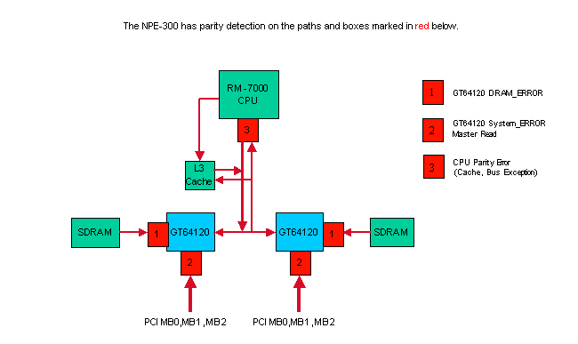
The NPE-300 uses parity checking in shared memory (SDRAM), PCI Bus, and the CPU’s external interface to protect the system from malfunctioning by bit errors. Parity checking is capable of detecting a single bit error by using a simple method; adding one check bit per eight bits of data. If it detects a bit error when passing the data between hardware components, the system discards the erroneous data. Single bit errors at any location in the diagram above cause the router to reset.
NPE-400 Parity/ECC Detection
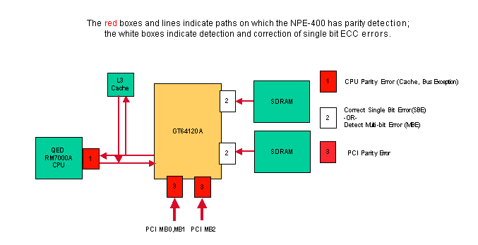
The NPE-400 uses Single Bit Error Correction and Multi-bit Error Detection ECC (Error Code Correction) for shared memory (SDRAM). To increase system availability in the NPE-400, ECC corrects single bit errors in SDRAM, to allow the system to operate normally without resetting and without down time. For more information on how ECC enhances system availability, refer to the Increasing Network Availability page.
A multi-bit error in SDRAM causes the router to reset with a cache error exception or bus error. The rest of the memory and buses in the system use single bit parity detection. Single bit errors at 1 and 3 in the diagram above cause the router to reset.
Parity Errors in the C7200 Router
Several of the parity checking devices on the C7200/NPE router can report data with bad parity for any read or write operation. Here is a description of the various error messages reported on a C7200/NPE system:
GT64010/GT64120 DRAM Error
This error is reported when a GT64120 system controller detects a parity error when reading SDRAM:
%ERR-1GT64120 (PCI0):Fatal error, Memory parity error (external)
GT=0xB4000000, cause=0x0100E283, mask=0x0ED01F00, real_cause=0x00000200
Bus_err_high=0x00000000, bus_err_low=0x00000000,
addr_decode_err=0x1C000000
Replace the SDRAM after a second failure. If the failure persists, replace the NPE.
Note: For older NPEs (NPE-100/150/200) which use the GT64010 controllers, the error looks like this:
%ERR-1-GT64010: Fatal error, Memory parity error (external)
cause=0x0300E283, mask=0x0CD01F00, real_cause=0x00000200
bus_err_high=0x00000000, bus_err_low=0x00000000, addr_decode_err=0x00000000
The GT64010 controller uses Dynamic RAM (DRAM) and not SDRAM. In this case, replace the DRAM after a second failure. If the failure persists, replace the NPE.
GT64010/GT64120 System Parity Error Master Read
A parity error in Master Read is a parity error triggered by accessing a Peripheral Component Interconnect (PCI) bridge. Here’s an example of parity error output:
%ERR-1-GT64120 (PCI0):Fatal error, Parity error on master read
GT=B4000000, cause=0x0110E083, mask=0x0ED01F00, real_cause=0x00100000
Bus_err_high=0x00000000, bus_err_low=0x00000000,
addr_decode_err=0x00000470

%ERR-1-SERR: PCI bus system/parity error
%ERR-1-FATAL: Fatal error interrupt, No reloading
Err_stat=0x81, err_enable=0xFF, mgmt_event=0x40
Replace the appropriate component after a second failure. The system bridge dump indicates which component to replace.
System bridge dump:

Bridge 1, for PA bay 1, 3 and 5. Handle=1
DEC21150 bridge chip, config=0x0

(0x1C):sec status, io base =0x83A09141
                Detected Parity Error on secondary bus
                Data Parity Detected on secondary bus
(0x20):mem base & limit =0x4AF04880
These tables tell you which component has a possible problem from the error message output.
NPE-100/150/200:
| Bridge number | What the bridge is for | Parity Error on Primary Bus | Parity Error on Secondary Bus |
|---|---|---|---|
| Bridge 0 | Downstream MB0 to MB1 0 | Replace the NPE | Replace NPE; if still present, replace chassis |
| Bridge 1 | Upstream MB1 to MB0 | Replace NPE; if still present, replace chassis | Replace the NPE |
| Bridge 2 | Downstream MB0 to MB2 | Replace the NPE | Replace NPE; if still present, replace chassis |
| Bridge 3 | Upstream MB2 to MB0 | Replace NPE; if still present, replace chassis | Replace the NPE |
NPE-175/225/300/400/NSE-1:
| Bridge number | What the bridge is for | Parity Error on Primary Bus | Parity Error on Secondary Bus |
|---|---|---|---|
| Bridge 0 | For PA bay 0 (I/O card, PCMCIA, interfaces | Replace the NPE | Replace NPE; if still present, replace I/O card. If still present, replace chassis |
| Bridge 1 | For PA bay 1, 3, and 5 | Replace the NPE | Replace the NPE; if still present, replace chassis |
| Bridge 2 | For PA bay 2, 4, and 6 | Replace the NPE | Replace NPE; if still present, replace chassis |
All C7200s:
| Bridge number | What the bridge is for | Parity Error on Primary Bus | Parity Error on Secondary Bus |
|---|---|---|---|
| Bridge 4 | Port Adapter 1 | Replace NPE; if still present, replace chassis | Replace PA 1; if still present, replace chassis |
| Bridge 5 | Port Adapter 2 | Replace NPE; if still present, replace chassis | Replace PA 2; if still present, replace chassis |
| Bridge 6 | Port Adapter 3 | Replace NPE; if still present, replace chassis | Replace PA 3; if still present, replace chassis |
| Bridge 7 | Port Adapter 4 | Replace NPE; if still present, replace chassis | Replace PA 4; if still present, replace chassis |
| Bridge 8 | Port Adapter 5 | Replace NPE; if still present, replace chassis | Replace PA 5; if still present, replace chassis |
| Bridge 9 | Port Adapter 6 | Replace NPE; if still present, replace chassis | Replace PA 6; if still present, replace chassis |
CPU Parity Error
As with all computer and networking devices, the NPE is susceptible to the rare occurrence of parity errors in processor memory. Parity errors may cause the system to reset and can be a transient Single Event Upset (SEU or soft error) or can occur multiple times (often referred to as hard errors) due to damaged hardware. For more information on SEUs, refer to the Increasing Network Availability page. A CPU parity error is reported if the CPU detects a parity error when accessing any of the processor’s caches (L1, L2, or if fitted, L3).
Here are four examples of this type of error:
Example 1:
Error: SysAD, data cache, fields: data, 1st dword
Physical addr(21:3) 0x195BE88,
Virtual address is imprecise.
    Imprecise Data Parity Error
    Imprecise Data Parity Error
The NPE has an R7K processor with non-blocking cache. Non-blocking cache means when it executes an instruction to load data into a register and this data is not in the L1 cache, the CPU loads the data from a lower order cache or from SDRAM data. The CPU does not block execution of further instructions unless there is another cache miss or another instruction depends upon the data being loaded. This can greatly speed up the processor and improve performance, but can also lead to parity errors being imprecise. An imprecise parity error is when the CPU reads information without blocking, and later determines there was a parity error in the associated cache line. The R7K processor is unable to tell us specifically which instruction was being executed when the cache line was being loaded, and that is the reason we call it an imprecise parity error.
Even if systems use Error Code Correction (ECC), it is still possible to see an occasional parity error when more than a single error has occurred in the 64 bits of data due to a hard error in the cache.
A parity error occurs when a signal bit value is changed from its original value (0 or 1) to the opposite value. This error can occur either due to a soft or hard parity error.
Soft parity errors occur because of an external influence on the memory of the device, which changes the bit value at the current level. This type of problem is transient and does not reoccur. Hard parity errors occur when the bit value is changed by the memory itself because of damage to the memory. In that case, the problem occurs every time that area of memory is used, which means that the problem can repeat multiple times within a couple days to a week.
Example 2:
Error: SysAD, instr cache, fields: data, 1st dword
Physical addr(21:3) 0x000000,
virtual addr 0x6040BF60, vAddr(14:12) 0x3000
virtual address corresponds to main:text, cache word 0

          Low Data     High Data  Par  Low Data     High Data  Par
L1 Data:  0:0xAE620068 0x8C830000 0x00 1:0x50400001 0xAC600004 0x01
          2:0xAC800000 0x00000000 0x02 3:0x1600000B 0x00000000 0x01
           Low Data     High Data  Par  Low Data     High Data  Par
DRAM Data: 0:0xAE620068 0x8C830000 0x00 1:0x50400001 0xAC600004 0x01
           2:0xAC800000 0x00000000 0x02 3:0x1600000B 0x00000000 0x01
Example 3:
Cache Err Reg = 0xE4588D10
Data reference, Secondary/Sys intf cache, Data field error
Error on 1st doubleword on System interface
No errors in addition to instr error
Data phy addr that caused last parity or bus error: 0x1E84040C
Example 4 (NPE-300 and NPE-400 only):
%CERF-3-RECOVER: PC=0x604F136C, Origin=L3 Data ,PhysAddr=0x013CEFD0
or
%SYS-2-CERF_ABORT: Reason=0xEE23, PC=0x604629C8, Origin=L3 Data,
Phys Addr=0x0287A4E8
Both messages above are accompanied by a «Cache Error Recovery Function (CERF) report» as follows:
CERFa[1 ] 05:25:36 MET Tue Jul 9 2002: result=0xEE23; instr_pos=-2; rpl_off=1
CERFb[1 ] PC =604629C8; ORGN=L3 Data; PRID=00002710; PHYA=0287A4E8
CERFc[1 ] SREG=3400E105; CAUS=00000400; DEA0=0287A4E8; ECC =00000000
CERFd[1 ] CERR=E447A4EA; EPC =606361F8; DEA1=02517058; INFO=00000000
CERFe[1 ] CACHE=28FF78B4 62B36D98 02020684 00000E17 00000030 00000001 61F2934C 3EDA025D
CERFe[1 ] SDRAM=28FF78B4 62B36D98 02020684 00000E17 00000030 00000001 61F2934C 3EDA025D
CERFg[1 ] CXT =00000000; XCXT=00000000; BVAD=00000008; PFCL=00000000
CERFh[1 ] ISeq: 0045182B; 1060000E; 2C4203E9; 92430028; 38420001; 30630005
CERFi[1 ] o0 $3 ....; beq....; sltiu $2 ....; lbu $3, 0x0028($18); xori $2....; andi $3 ....;*
CERFj[1 ]           ;        ;              ;            6287A4E8;            ;             ;
CERFk[1 ] ResumptionCode= 0x92430028; 0x0000000F; 0x42000018
CERFl[1 ] Instr's checked=4; diags=0x00000158,0x00040000,3600,1,0
CERFm[1 ] BaseRegLost later/off: 0/0 times; StoredValueLost: 0 times
CERFn[1 ] INFO=00000000; CNFG=5061F4BB; ICTL=00000000

Initial Register Values
CERFs00[1 ] $0=00000000 AT=61A30000 v0=00000001 v1=00000002
CERFs04[1 ] a0=28FF8728 a1=00003A98 a2=00000000 a3=00000007
CERFs08[1 ] t0=00000000 t1=3400E101 t2=606381E0 t3=FFFF00FF
CERFs12[1 ] t4=606381C8 t5=000005D4 t6=00000008 t7=61C50000
CERFs16[1 ] s0=6189C188 s1=00000000 s2=6287A4C0 s3=00003A98
CERFs20[1 ] s4=61BD57B0 s5=00000006 s6=00000000 s7=61BD6C60
CERFs24[1 ] t8=60634788 t9=00000000 k0=621A8374 k1=6063EA40
CERFs28[1 ] gp=61A33B20 sp=61E28678 s8=00000000 ra=60462CA4

1 Cache error exceptions already reported
You see the above logs if CERF is enabled on an NPE-300 or NPE-400 and a parity error occurs. For more information about CERF, refer to the Solutions section below.
Solutions
The following course of action is recommended when you encounter such errors:
-
Monitor the affected hardware to see if the same problem happens again. If it does not, then it was a transient Single Event Upset (SEU) and you do not need to take any action.
-
In the unlikely event that the problem does reoccur, the cache L3 bypass/disable command is an option that may help reduce the impact of the issue. This command is only available on the following platforms:
-
7200 with processor engine NPE-300, NPE-400, or NSE-1
-
7400 with processor enginer NSE-1
Because the NPE-300 does not support ECC memory, this feature is especially important to increase system availability and handle these parity errors without service interruption. This resolves many soft parity errors. The caveat is that there is a slight performance hit to the system when L3 cache is disabled. The performance degradation is anywhere between 1% and 10% depending upon the system configuration. The syntax for using this command is dependent on the Cisco IOS software version.
-
The cache L3 disable command can be found in Cisco IOS Software Releases 12.3(5a) and later. It will also be available in 12.1(22)E. In these versions, L3 cache is disabled by default, so no action is needed to take advantage of this feature. L3 cache can be reenabled with the command no cache L3 disable.
-
The cache L3 bypass command can be found in Cisco IOS Software Releases 12.2(6)S, 12.2(6)B, 12.2(8)BC1b, 12.0(20)SP, 12.2(6)PB, 12.2(2)DD2, 12.0(20)ST3, 12.0(21)S, 12.1(11)EC, 12.2(7)T, 12.1(13), and 12.2(7) or later, and 12.1(11)E through 12.1(21)E. This command is disabled by default.
To enable L3 cache bypass, enter the following from configuration mode:
Router(config)#cache L3 bypass
To disable L3 cache bypass, enter the following from configuration mode:
Router(config)#no cache L3 bypass
The new cache setting does not take effect until the router is reloaded.
When the router boots up, system information is displayed, including information about the L3 cache. This is because the startup-config file has not yet been processed by the system. After the startup-config file is processed, the L3 cache is bypassed if the cache L3 bypass command is in the configuration.
To verify the L3 cache setting, you can issue the show version command. If the L3 cache is bypassed, there is no reference to the L3 cache in the show version output.
-
-
Another feature that helps increase system availability is the Cache Error Recovery Function (CERF). When this feature is enabled (this is the default in the latest Cisco IOS software releases, but as of February 2004, only for NPE-300 and NPE-400), the Cisco IOS software makes an attempt to resolve the parity error and keep the processor from crashing. This feature resolves around 75% of certain types of soft parity errors. By invoking this command, the system sees less than 5% performance degradation.
CERF for the NPE-300 can be found in Cisco IOS Software Releases 12.1(15), 12.1(12)EC, 12.0(22)S, 12.2(10)S, 12.2(10)T, 12.2(10), 12.2(2)XB4, 12.2(11)BC1b, and 12.1(5)XM8 or later.
CERF for the NPE-400 can be found in 12.3(3)B, 12.2(14)S3, 12.1(20)E, 12.1(19)E1, 12.3(1a), 12.2(13)T5, 12.2(18)S, 12.3(2)T, 12.2(18), 12.3(3), and 12.3(1)B1 or later.
CERF for the NPE-300 requires hardware revision 4.1 or higher. In order to identify the hardware version of your NPE-300, use the show c7200 command.
Router>show c7200
...
C7206VXR CPU EEPROM:
Hardware revision 4.1 Board revision A0

	  ...
CERF for the NPE-400 requires processor R7K revision 2.1 or higher. In order to identify the processor revision of your NPE-400, use the show version command.
Router>show version
...
cisco 7206VXR (NPE400) processor with 491520K/32768K bytes of memory.
R7000 CPU at 350Mhz, Implementation 39, Rev 3.2, 256KB L2, 4096KB L3
Cache 6 slot VXR midplane, Version 2.1
...
Note: It is important to collect all relevant crashinfo files in order to determine the root cause of the error as explained in Retrieving Information from the Crashinfo File.
If the suggestions above do not resolve the issue, then replacing the NPE may help in cases of repeated occurrences of parity errors since hard parity errors are due to damaged hardware. Hardware replacements are identical to the original NPE. Replacing the NPE does not guarantee that no further parity errors will occur since Single Event Upsets (SEUs) are inherent in any computer equipment with memory.
Related Information
- Troubleshooting Router Crashes
- Processor Memory Parity Errors (PMPEs)
- Technical Support — Cisco Systems
Содержание
- Error-Detecting Codes — Parity
- Errors and Error Detection
- Parity Bits
- Error Detection by Parity Check
- Example
- Parity Check
- What Does Parity Check Mean?
- Techopedia Explains Parity Check
- How Parity Checking Works
- Limitations
- Error Detection in Computer Networks | Parity Check
- Error Detection in Computer Networks-
- Error Detection Methods-
- Single Parity Check-
- Steps Involved-
- Step-01:
- Step-02:
- Step-03:
- Parity Check Example-
- At Sender Side-
- At Receiver Side-
- Advantage-
- Limitation-
- EXAMPLE
- Parity Errors Troubleshooting Guide
- Available Languages
- Download Options
- Bias-Free Language
- Contents
- Introduction
- Background
- Soft Errors
- Hard Errors
- Common Error Messages
- Processor
- Latest Advancements
- Processor
- Software
- MSFC IBC Reset
- 6700 Series ‘Single-Bit Parity Error’ Reset
- Recommendations
- Soft Errors (SEU)
- Environmental Audit
- Latest Firmware (Rommon)
- Thumb Screws
- Hard Errors (Malfunction)
- Hardware (MTBF and EOL) Audit
- Hardware Diagnostics
Error-Detecting Codes — Parity
Errors and Error Detection
When bits are transmitted over the computer network, they are subject to get corrupted due to interference and network problems. The corrupted bits leads to spurious data being received by the receiver and are called errors.
Error detection techniques are responsible for checking whether an error has occurred or not in the frame that has been transmitted via the network. It does not take into account the number of error bits and the type of error.
For error detection, the sender needs to send some additional bits along with the data bits. The receiver performs necessary checks based upon the additional redundant bits. If it finds that the data is free from errors, it removes the redundant bits before passing the message to the upper layers.
There are three main techniques for detecting errors in data frames: Parity Check, Checksum and Cyclic Redundancy Check (CRC).
Parity Bits
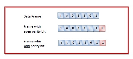
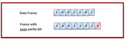
The parity check is done by adding an extra bit, called parity bit, to the data to make the number of 1s either even or odd depending upon the type of parity. The parity check is suitable for single bit error detection only.
The two types of parity checking are
Even Parity − Here the total number of bits in the message is made even.
Odd Parity − Here the total number of bits in the message is made odd.
Error Detection by Parity Check
Sender’s End − While creating a frame, the sender counts the number of 1s in it and adds the parity bit the value of which is determined as follows —
- In the case of even parity: If a number of 1s is even, the parity bit value is 0. If a number of 1s is odd, the parity bit value is 1.
- In case of odd parity: If a number of 1s is odd, the parity bit value is 0. If a number of 1s is even, the parity bit value is 1.

Receiver’s End − On receiving a frame, the receiver counts the number of 1s in it. In case of even parity check, if the count of 1s is even, the frame is accepted, otherwise, it is rejected. In case of odd parity check, if the count of 1s is odd, the frame is accepted, otherwise, it is rejected.
Example
Suppose that a sender wants to send the data 1001101 using even parity check method. It will add the parity bit as shown below.
The receiver will decide whether an error has occurred by counting whether the total number of 1s is even. When the above frame is received, three cases may occur namely, no error, single bit error detection and failure to detect multiple bits error. This is illustrated as follows —
Источник
Parity Check
Table of Contents
What Does Parity Check Mean?
A parity check is an error-correction process in network communication that ensures data transmissions between communication nodes are accurate. In this process, the receiver agrees to use the same even parity bit or odd parity bit scheme as the sender. In an even parity check, parity bits ensure there are an even number of 1s and 0s in the transmission. In an odd parity check, there are an odd number of 1s and 0s in the transmission.
Once the source transmits data, the number of bits is checked by the receiver. If the number of received bits does not match what was agreed upon, it raises a red flag about the transmission’s accuracy and future communication may be halted until the reason for the mismatch has been identified.
Techopedia Explains Parity Check
Parity checking, which was created to eliminate data communication errors, has an easy to understand working mechanism. Parity bits are optional and there are no rules for where a parity bit has to be placed, but conventionally, parity bits are added at the end of the data transfer.
How Parity Checking Works
Imagine a data transfer that looks like this: 1010001. This example has an odd number of 1s and and even number of 0s.
When an even parity checking is used, a parity bit with value 1 could be added to the data’s right side to make the number of 1s even — and the transmission would look like this: 10100011. If an odd parity check was used, the transmission would look like this: 10100010.
Redundant array of independent disks (RAID) also uses an enhanced form of parity check protection. A second set of parity data is written across all drives to avoid data loss in case of error.
When a RAID drive fails its parity check, data is rebuilt using parity information coupled with data on the other disks. The bits on the remaining drives are added up. If they add up to an odd number, the correct information on the failed drive has to be even, and vice-versa, for communication to continue.
Limitations
Parity checking is primarily used for communications, although more advanced protocols such as the Microcom Networking Protocols (MNP) and ITU-T V.42b has supplanted it as the standard in modem-to-modem communication.
Although parity checking provides a very basic method for detecting simple errors, it cannot, for example, detect errors caused by electrical noise changing the number of bits. It might happen, in fact, that both the receiving and sending bits are in error, offsetting each other.
Although the chance for this to happen in a PC is basically remote, in large computer systems where there’s an essential need to ensure data integrity, a third bit could be allocated for parity checking.
Источник
Error Detection in Computer Networks | Parity Check
Error Detection in Computer Networks-
When sender transmits data to the receiver, the data might get scrambled by noise or data might get corrupted during the transmission.
Error detection is a technique that is used to check if any error occurred in the data during the transmission.
Error Detection Methods-
Some popular error detection methods are-
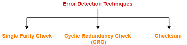
- Single Parity Check
- Cyclic Redundancy Check (CRC)
- Checksum
In this article, we will discuss about Single Parity Check.
Single Parity Check-
In this technique,
- One extra bit called as parity bit is sent along with the original data bits.
- Parity bit helps to check if any error occurred in the data during the transmission.
Steps Involved-
Error detection using single parity check involves the following steps-
Step-01:
- Total number of 1’s in the data unit to be transmitted is counted.
- The total number of 1’s in the data unit is made even in case of even parity.
- The total number of 1’s in the data unit is made odd in case of odd parity.
- This is done by adding an extra bit called as parity bit.
Step-02:
- The newly formed code word (Original data + parity bit) is transmitted to the receiver.
Step-03:
At receiver side,
- Receiver receives the transmitted code word.
- The total number of 1’s in the received code word is counted.
Then, following cases are possible-
- If total number of 1’s is even and even parity is used, then receiver assumes that no error occurred.
- If total number of 1’s is even and odd parity is used, then receiver assumes that error occurred.
- If total number of 1’s is odd and odd parity is used, then receiver assumes that no error occurred.
- If total number of 1’s is odd and even parity is used, then receiver assumes that error occurred.
Parity Check Example-
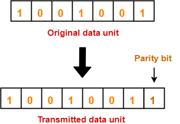
Consider the data unit to be transmitted is 1001001 and even parity is used.
At Sender Side-
- Total number of 1’s in the data unit is counted.
- Total number of 1’s in the data unit = 3.
- Clearly, even parity is used and total number of 1’s is odd.
- So, parity bit = 1 is added to the data unit to make total number of 1’s even.
- Then, the code word 10010011 is transmitted to the receiver.
At Receiver Side-
- After receiving the code word, total number of 1’s in the code word is counted.
- Consider receiver receives the correct code word = 10010011.
- Even parity is used and total number of 1’s is even.
- So, receiver assumes that no error occurred in the data during the transmission.
Advantage-
- This technique is guaranteed to detect an odd number of bit errors (one, three, five and so on).
- If odd number of bits flip during transmission, then receiver can detect by counting the number of 1’s.
Limitation-
- This technique can not detect an even number of bit errors (two, four, six and so on).
- If even number of bits flip during transmission, then receiver can not catch the error.
EXAMPLE
- Consider the data unit to be transmitted is 10010001 and even parity is used.
- Then, code word transmitted to the receiver = 100100011
- Consider during transmission, code word modifies as 101100111. (2 bits flip)
- On receiving the modified code word, receiver finds the number of 1’s is even and even parity is used.
- So, receiver assumes that no error occurred in the data during transmission though the data is corrupted.
To gain better understanding about single parity check,
Get more notes and other study material of Computer Networks.
Watch video lectures by visiting our YouTube channel LearnVidFun.
Источник
Parity Errors Troubleshooting Guide
Available Languages
Download Options
Bias-Free Language
The documentation set for this product strives to use bias-free language. For the purposes of this documentation set, bias-free is defined as language that does not imply discrimination based on age, disability, gender, racial identity, ethnic identity, sexual orientation, socioeconomic status, and intersectionality. Exceptions may be present in the documentation due to language that is hardcoded in the user interfaces of the product software, language used based on RFP documentation, or language that is used by a referenced third-party product. Learn more about how Cisco is using Inclusive Language.
Contents
Introduction
This document describes soft and hard parity errors, explains common error messages, and recommends methods that help you avoid or minimize parity errors. Recent improvements in hardware and software design reduce parity problems as well.
Background
What is a processor or memory parity error?
Parity checking is the storage of an extra binary digit (bit) in order to represent the parity (odd or even) of a small amount of computer data (typically one byte) while that data is stored in memory. The parity value calculated from the stored data is then compared to the final parity value. If these two values differ, this indicates a data error, and at least one bit must have been changed due to data corruption.
Within a computer system, electrical or magnetic interference from internal or external causes can cause a single bit of memory to spontaneously flip to the opposite state. This event makes the original data bits invalid and is known as a parity error.
Such memory errors, if undetected, may have undetectable and inconsequential results or may cause permanent corruption of stored data or a machine crash.
There are many causes of memory parity errors, which are classified as either soft parity errors or hard parity errors.
Soft Errors
Most parity errors are caused by electrostatic or magnetic-related environmental conditions.
The majority of single-event errors in memory chips are caused by background radiation (such as neutrons from cosmic rays), electromagnetic interference (EMI), or electrostatic discharge (ESD). These events may randomly change the electrical state of one or more memory cells or may interfere with the circuitry used to read and write memory cells.
Known as soft parity errors, these events are typically transient or random and usually occur once. Soft errors can be minor or severe:
- Minor soft errors that can be corrected without component reset are single event upsets (SEUs).
- Severe soft errors that require a component or system reset are single event latchups (SELs).
Soft errors are not caused by hardware malfunction; they are transient and infrequent, are mostly likely a SEU, and are caused by an environmental disruption of the memory data.
If you encounter soft parity errors, analyze recent environmental changes that have occurred at the location of the affected system. Common sources of ESD and EMI that may cause soft parity errors include:
- Power cables and supplies
- Power distribution units
- Universal power supplies
- Lighting systems
- Power generators
- Nuclear facilities (radiation)
- Solar flares (radiation)
Hard Errors
Other parity errors are caused by a physical malfunction of the memory hardware or by the circuitry used to read and write memory cells.
Hardware manufacturers take extensive measures to prevent and test for hardware defects. However, defects are still possible; for example, if any of the memory cells used to store data bits are malformed, they may be unable to hold a charge or may be more vulnerable to environmental conditions.
Similarly, while the memory itself may be operating normally, any physical or electrical damage to the circuitry used to read and write memory cells may also cause data bits to be changed during transfer, which results in a parity error.
Known as hard parity errors, these events are typically very frequent and repeated and occur whenever the affected memory or circuitry is used. The exact frequency depends on the extent of the malfunction and how frequently the damaged equipment is used.
Remember that hard parity errors are the result of a hardware malfunction and reoccur whenever the affected component is used.
If you encounter hard parity errors, analyze physical changes that have occurred at the location of the affected system. Common sources of hardware malfunction that may lead to hard parity errors include:
- Power surges (no ground)
- ESD
- Overheating or cooling
- Incorrect or partial installation
- Component incompatibility
- Manufacturing defect
Common Error Messages
The Cisco IOS ® software provides a variety of parity error messages, which vary with the affected component and its relative impact on the system.
Processor
Cache error detected!
CP0_CAUSE (reg 13/0): 0x00000400
CPO_ECC (reg 26/0): 0x000000B3
CPO_BUSERRDPA (reg 26/1): 0x000000B3
CPO_CACHERI (reg 27/0): 0x20000000
Real cache error detected. System will be halted.
Error: Primary instr cache, fields: data,
Actual physical addr 0x00000000,
virtual address is imprecise.
Imprecise Data Parity Error
Explanation This is the result of a parity error within the Level 2 (L2) cache (static random-access memory, or SRAM) used by route processor (RP) or switch processor (SP) CPU of the Multilayer Switch Feature Card 3 (MSFC3). Recommendation Monitor the system regularly for reoccurrence. If no further events are observed, it is a soft error. If the error occurs frequently, request a Return Material Authorization (RMA) in order to replace the Supervisor Engine, and mark the module for equipment failure analysis (EFA). %SYSTEM_CONTROLLER-3-ERROR: Error condition detected: SYSAD_PARITY_ERROR Explanation This is the result of a parity error in the system address (data bus) used by the In-Band Controller (IBC) of the MSFC3. Recommendation Monitor the system regularly for reoccurrence. If no further events are observed, it is a soft error. If the error occurs frequently, request an RMA in order to replace the Supervisor Engine, and mark the module for EFA. %SYSTEM_CONTROLLER-3-ERROR: Error condition detected: TM_DATA_PARITY_ERROR Explanation This is the result of a parity error in the table manager data used by the IBC of the MSFC3. Recommendation Monitor the system regularly for reoccurrence. If no further events are observed, it is a soft error. If the error occurs frequently, request an RMA in order to replace the Supervisor Engine, and mark the module for EFA. %SYSTEM_CONTROLLER-3-ERROR: Error condition detected: TM_NPP_PARITY_ERROR Explanation This is the result of a parity error in the table manager ‘next page pointer’ used by the IBC of the MSFC3. Recommendation
Monitor the system regularly for reoccurrence. If no further events are observed, it is a soft error. If the error occurs frequently, request an RMA in order to replace the Supervisor Engine, and mark the module for EFA.
In Cisco IOS software versions between 12.1(8)E and 12.2(33)SXI3, the default behavior in response to SYSTEM_CONTROLLER-3-ERROR events was to reset the IBC and log an error message.
However, this corrective action resulted in some documented cases of the IBC (and thus, CPU) no longer being able to transmit or receive data. Thus, the behavior was changed in Cisco IOS software versions later than 12.2(33)SXI4 to log an error message and reset the system; refer to Cisco bug ID CSCtf51541.
Interrupt exception, CPU signal 20, PC = 0x[dec] Explanation This is the result of a single-bit parity error in the CPU L2 cache (SRAM) used by the Cisco Catalyst 6700 Series modules. Recommendation
Monitor the system regularly for reoccurrence. If no further events are observed, it is a soft error. If the error occurs frequently, request an RMA in order to replace the 6700 module, and mark the module for EFA.
In Cisco IOS software versions earlier than 12.2(33)SXI5, a software bug (Cisco bug ID CSCtj06411) would cause even single-bit parity errors to reset the 6700 module. This was resolved in Versions 12.2(33)SXI6 and 12.2(33)SXJ for Supervisor Engine 720 and in Version 15.0SY for Supervisor Engine 2T.
This is the result of a single-bit parity error in the DRAM used by 6700 Series modules.
Monitor the system regularly for reoccurrence. If no further events are observed, it is a soft error. If the error occurs frequently, clean and reseat the DIMM, and continue to monitor. If the error continues, request an RMA in order to replace or upgrade the DIMM.
Monitor the system regularly for reoccurrence. If no further events are observed, it is a soft error. If the error occurs frequently, request an RMA in order to replace the 6100 or 6300 module, and mark the module for EFA.
| %SYSTEM_CONTROLLER-3-ERROR: Error condition detected: SYSDRAM_PARITY_ERROR | |
| Explanation | This is the result of an uncorrectable parity error in the synchronous DRAM (SDRAM) memory modules (DIMM) used by the MSFC3. |
| Recommendation | Monitor the system regularly for reoccurrence. If no further events are observed, it is a soft error. If the error occurs frequently, clean and reseat the DIMM, and continue to monitor. If the error continues, request an RMA in order to replace or upgrade the DIMM. |
| %SYSTEM_CONTROLLER-3-COR_MEM_ERR: Correctable DRAM memory error. Count [dec], log [hex] | |
| Explanation | This is the result of a correctable parity error in the SDRAM (DIMM) used by the MSFC3. |
| Recommendation | Monitor the system regularly for reoccurrence. If no further events are observed, it is a soft error. If the error occurs frequently, clean and reseat the DIMM, and continue to monitor. If the error continues, request an RMA in order to replace or upgrade the DIMM. |
| %MWAM-DFC[dec]-0-CORRECTABLE_ECC_ERR: A correctable ECC error has occurred, A_BUS_L2_ERRORS: 0x10000, A_BUS_MEMIO_ERRORS: 0x0, A_SCD_BUS_ERR_STATUS: 0x80983000 | |
| Explanation | |
| %PM_SCP-SP-2-LCP_FW_ERR_INFORM: Module [dec] is experiencing the following error: LTL Parity error detected on Coil #[dec]. | |
| Explanation | This is the result of a parity error in the SRAM used by the Cisco Catalyst 6100 and Cisco Catalyst 6300 Series modules. |
| Recommendation | |
| %SYS-4-SYS_LCPERR4: Module [dec]: LTL Parity error detected on Coil #[dec] | |
| Explanation | This is the result of a parity error in the SRAM used by the 6100 and 6300 Series modules. |
| Recommendation | Monitor the system regularly for reoccurrence. If no further events are observed, it is a soft error. If the error occurs frequently, request an RMA in order to replace the 6100 or 6300 module, and mark the module for EFA. |
Monitor the system regularly for reoccurrence. If no further events are observed, it is a soft error. If the error occurs frequently, request an RMA in order to replace the 6148A module, and mark the module for EFA.
| %PM_SCP-SP-2-LCP_FW_ERR_INFORM: Module [dec] is experiencing the following error: Port ASIC ([name]) packet buffer failure detected on ports [dec] | |
| Explanation | This is the result of a parity error in the port ASIC packet buffer (SRAM) used by the Cisco Catalyst 6148A Series Ethernet modules. |
| Recommendation | |
| %LTL-SP-2-LTL_PARITY_CHECK: LTL parity check request for 0x[hex] | |
| Explanation | This is the result of a parity error in the port ASIC port index table (SRAM) used by the Catalyst 6100-6500 and 6700 Series modules. |
| Recommendation | Monitor the system regularly for reoccurrence. If no further events are observed, it is a soft error. If the error occurs frequently, request an RMA in order to replace the module, and mark the module for EFA. |
Refer to these Cisco IOS software documents for a comprehensive list of error messages:
The Output Interpreter Tool (registered customers only) supports certain show commands. Use the Output Interpreter Tool in order to view an analysis of show command output.
Latest Advancements
Research into the field of parity errors is ongoing, and not every scenario can be addressed, but the Cisco Catalyst 6500 hardware and software development organizations continue to introduce new ways, such as error-correcting code (ECC) protection, to minimize and mitigate the occurrence of parity errors.
While this document began with discussion of the third generation (WS-XSUP720 and early 6700 Series) of Catalyst 6500 products, this section summarizes improvements introduced with the fourth generation (VS-S720-10G and later 6700 Series) and the fifth generation (VS-SUP2T-10G and 6900 Series).
Processor
The VS-S720-10G module features a newer MSFC3 daughterboard, with a new IBC and updated SR7010A reduced instruction set computing (RISC) RP and SP CPUs that operate at 600Mhz each. The Level 1 (L1), L2, and Level 3 (L3) caches are capable of parity detection. The newer IBC has all of the functionality of the earlier generation and adds ECC protection (single-bit correction, multi-bit detection) to the attached SRAMs.
The 6700 Series modules support a CPU with ECC-protected L2 cache (L1 cache is parity detection capable), which can correct single-bit parity errors without the need to reset. However, due to Cisco bug ID CSCsz39222, Version 12.2SXI of the Cisco IOS software (Supervisor Engine 720) resets the module anyway if a single-bit CPU cache parity error occurs. This is resolved in Versions 12.2SXJ (Supervisor Engine 720) and 15.0SY (Supervisor Engine 2T) of the Cisco IOS software.
The VS-SUP2T-10G features a new MSFC5 daughterboard with an integrated IBC and a new single, dual-core MPC8572 PPC RP CPU (with ECC-protected L2 and L3 cache, L1 cache is parity detection capable) that operates at 1.5Ghz per core. It also features a new, separate, out-of-band Connectivity Management Processor (CMP) CPU and ECC-protected DRAM, which is available even if the RP CPU is currently unavailable.
The new IBC has all of the functionality of earlier generations and supports ECC protection for the attached SRAMs and improvements in parity error handling. The new MSFC5 also features an Onboard Failure Logging (OBFL) ROM, which stores all module initialization and diagnostics events. The new single CPU design also reduces the statistical likelihood of parity error events.
The 6900 Series modules support a newer CPU with ECC-protected L1 and L2 cache, which can correct single-bit parity errors without the need to reset. The new generation supports the same IBC, and the software handling for single-bit parity error correction has been incorporated.
The VS-S720-10G with MSFC3 features double-data-rate (DDR) SDRAM with ECC protection, operating at 266Mhz.
The 6700 Series modules support DDR SDRAM with ECC protection, operating at 266Mhz.
Compared to single-data-rate (SDR) SDRAM, the DDR SDRAM interface makes higher transfer rates possible by more strict control of the timing of the electrical data and clock signals. The DDR interface uses double pumping (data transfer on both the rising and falling edges of the clock signal) in order to lower the clock frequency. Lower clock frequency reduces the signal integrity requirements on the circuit board that connects the memory to the controller.
The VS-SUP2T-10G with MSFC5 features DDR3 SDRAM with ECC protection, operating at 667Mhz.
The 6900 Series modules support DDR3 SDRAM with ECC protection, operating at 667Mhz.
The primary benefit of DDR3 SDRAM over its immediate predecessors (DDR2 and DDR) is its ability to transfer data at twice the rate (eight times the speed of its internal memory arrays), which enables higher bandwidth or peak data rates. DDR3 memory also reduces power consumption by 30%, even though it uses the same electric signaling standard as DDR and DDR2.
The VS-S720-10G with PFC3C features SRAM packet buffers with ECC protection. This provides single-bit parity error correction without module reset, as well as multi-bit parity error detection.
The 6700 Series with DFC3C features SRAM packet buffers with ECC protection. This provides single-bit parity error correction without module reset, as well as multi-bit parity error detection.
The VS-SUP2T-10G with PFC4 features SRAM packet buffers with ECC protection. This provides single-bit parity error correction without module reset, as well as multi-bit parity error detection.
The 6900 Series with DFC4 features SRAM packet buffers with ECC protection. This provides single-bit parity error correction without module reset, as well as multi-bit parity error detection.
Software
The Cisco IOS software is designed to support ECC protection. If a hardware component that supports ECC protection experiences an SEU, the code should correct the corrupt data or reset the affected component and not require a full hardware reset of the affected module.
However, in earlier versions of Cisco IOS software, there are a few exceptions where the behavior has been intentionally changed or malfunctions due to a software bug. Here are two notable exceptions.
MSFC IBC Reset
In Cisco IOS software versions between 12.1(8)E and 12.2(33)SXI3, the default behavior in response to SEU SYSTEM_CONTROLLER-3-ERROR events was to reset the IBC and log an error message. However, this corrective action resulted in some documented cases of the IBC (and thus, CPU) no longer being able to transmit or receive data.
Thus, the behavior was changed after Version 12.2(33)SXI4 (Cisco bug ID CSCtf51541) to log an error message and reset the system. While this reaction may seem more severe, it is preferable to reset the system and correct the memory structure than to have an unresponsive system.
A feature now in development (Cisco bug ID CSCtr89859) will add a new command-line interface (CLI) command that lets you switch the default behavior. This enhancement is most applicable to systems that use a single supervisor and thus have no supervisor redundancy.
6700 Series ‘Single-Bit Parity Error’ Reset
In Cisco IOS software versions earlier than12.2(33)SXI5, a software bug (Cisco bug ID CSCtj06411) would cause even single-bit parity errors to reset the 6700 module. This would normally be a correctable parity error and not require the module to be reset.
This bug was resolved in Versions 12.2(33)SXI6+ and 12.2SXJ for Supervisor Engine 720 and in Version 15.0SY for Supervisor Engine 2T. After an upgrade to the appropriate version, the 6700 module simply logs an error message and continues to operate.
Recommendations
By this point, you have probably determined whether you have encountered a soft or hard parity error. While this may address a single incident, other parity error vulnerabilities may still exist, so you should take a more comprehensive approach to your entire network.
Thus, Cisco and the Catalyst 6500 business unit recommend that you review these mitigation procedures and take appropriate corrective actions in order to eliminate or reduce future parity errors.
Soft Errors (SEU)
Single event (soft) parity errors are caused by environmental conditions and may occur only once (SEU) or very infrequently, such as monthly or yearly. Although you do not need to replace the hardware, you do want to mitigate future occurrences.
These best practices significantly reduce the likelihood of soft parity errors.
Environmental Audit
Cisco recommends that you perform an environmental audit of your affected network locations. You may perform this audit yourself or in coordination with a Cisco representative, with a Cisco team (such as Cisco Advanced Services), or through a third-party consultant.
The exact coverage and complexity of an environmental audit depend on many different variables such as geographic location, building and room size and design, electrical design and layout, and other related factors.
Consider what environmental sources of ESD and EMI may exist in or around your network. These are common sources of interference that may lead to a soft parity error:
- Power cables and supplies
- Power distribution units
- Universal power supplies
- Lighting systems
- Power generators
- Nuclear facilities (radiation)
- Solar flares (radiation)
Chassis Placement
SEUs can occur if power distribution units, power generators, or lighting systems are too close to the chassis or if multiple power cables are on or beside the chassis.
It is important to provide adequate distance between the Catalyst 6500 chassis and these electrical and magnetic sources. Recommended distances vary by component and are available from the component datasheets.
In general, Cisco recommends you locate systems at least three to six inches from common sources of electrical and magnetic interference. Power cables should be routed down and away from the chassis, wherever possible, and should not be laid in tightly packed bundles or in large numbers across or beside the chassis.
Grounding
Power fluctuations and power surges are relatively common, and Catalyst 6500 power supplies are designed to accommodate minor variations in voltage current.
However, it is critical to provide proper electrical grounding for the chassis and rack so any excess electrical voltage is drawn away from the system. Without proper grounding, power surges may result in damage or malfunction in various ASICs and memory components. Refer to the Catalyst 6500 Series Switch Installation Guide, Installing the Switch, Establishing the System Ground, for more information.
ESD can easily damage critical components without any visible impairment. Appropriate preventive measures should be incorporated into lab operation policies, but such measures are often and unfortunately ignored due to expedience and limited oversight.
Cisco recommends that your lab operations management, along with Cisco Systems, perform an environmental audit of all network areas or, at a minimum, of all areas that have exhibited hardware failures or have been designated as mission critical. Once the audit is complete, Cisco recommends that you implement a standardized environmental checklist for all newly installed systems in order to avoid future SEU parity events.
Latest Firmware (Rommon)
Catalyst hardware components use firmware (also known as Rommon) code to initialize, communicate, and run diagnostics. Once these functions are complete, system operation is turned over to the Cisco IOS software. It is uncommon to experience issues with firmware, but there can be issues if you use different versions of firmware code for the Supervisors and the modules.
Thus, it is a best practice to ensure that all components use the latest firmware code in order to ensure proper module initialization and communication. Cisco recommends that your operations management perform a network audit and upgrade all hardware components with the latest firmware version.
Known firmware issues and upgrade procedures are documented in:
Download the latest firmware versions from the Cisco web site:
Thumb Screws
All modular networking systems are designed to insert into a chassis backplane with a set of physical interface pins. The chassis backplane itself is essentially a series of interconnected wires. The pins in each chassis slot form the physical data connection between the Supervisor and Ethernet modules. Thus, proper insertion and alignment of these pins is critical.
The Catalyst 6500 provides guide rails and alignment pins that assist in the installation in the chassis. The slot pins (sockets) and module connectors are designed to easily engage and provide high-bandwidth capable electrical connectivity. Once inserted into the chassis, there are thumb screws on either side of the module that fully engage the backplane pins. Refer to the Catalyst 6500 Series Switch Module Installation Note.
If a module has been properly inserted into the slot and the thumb screws have been correctly tightened, no communication problems are expected. However, several conditions may occur in day-to-day insertion of modules that can lead to improper or even incomplete pin insertion:
- Insufficient insertion force — If the module is partially inserted without use of the thumb screws, this may cause bus stalls, and the module may not be able to communicate with other modules. Depending on the level of insertion (for example, if there is limited physical contact), the module may be able to transmit and receive data, but may experience bit errors that result in corrupt packets.
- Vertical misalignment — This occurs when only one side of the module is on the guide rails. This is easily identified because the module appears diagonal and does not usually connect with the backplane pins.
- Horizontal misalignment — If thumb screws are used on only one side, some of the pins do not engage properly. This is a common problem, because the module may appear to be properly inserted. Horizontal misalignment is actually a form of insufficient insertion force.
Cisco recommends that you implement an operation management process that mandates the use of the thumb screws on all Catalyst 6500 modules in production environments. This ensures proper and full insertion and alignment of backplane pins and prevents future failures due to bit errors and related communication failures.
Hard Errors (Malfunction)
Frequent or repeatable (hard) parity errors are caused by physical malfunction of the memory or the circuitry used to read and write. In such cases, replace the hardware and ask the Cisco Technical Assistance Center (TAC) or your Cisco Systems Engineer to conduct an EFA on the returned hardware.
These best practices significantly reduce the likelihood of hard parity errors.
Hardware (MTBF and EOL) Audit
Cisco recommends that you perform a network audit of your affected network locations. You may perform this audit yourself or in coordination with a Cisco representative, with a Cisco team (such as Cisco Advanced Services), or through a third-party consultant.
All hardware (from all vendors) is subject to eventual degradation of physical integrity, and it is important to track the life cycle of all hardware components in your network in order to fully understand the likelihood of component failure over time.
Hardware reliability can be measured with the mean time between failure (MTBF) framework. Since MTBF is only a statistical average, this does not mean that a failure will definitely occur at the end of the MTBF time period. However, the likelihood and vulnerability of component failure increases, so such hardware should be flagged for refresh. Refer to the Cisco Catalyst 6500 Series Switches Data Sheets for specific MTBF values for each Catalyst 6500 product.
In addition to the MTBF framework, Cisco also provides an end-of-life (EOL) framework, which defines the expected life cycle of a given product and provides applicable announcements in order to help you refresh your legacy equipment. Refer to the End-of-Life and End-of-Sale Notices for various legacy Catalyst 6500 products.
As a result of this hardware audit, Cisco recommends that you implement your own MTBF and EOL process that identifies and tracks hardware for potential refresh. This ensures that the latest hardware is running and minimizes the likelihood of hardware malfunction.
Hardware Diagnostics
The Catalyst 6500 Series and Cisco IOS software provides Generic Online Diagnostics (GOLD) and Health Monitoring (HM) diagnostics for all hardware components used in the system. The two basic types of diagnostics that can be enabled are on-demand and boot-up. Refer to Generic Online Diagnostics on the Cisco Catalyst 6500 Series Switch for additional information.
Cisco recommends that ‘complete’ boot-up diagnostics be enabled for all hardware components in order to ensure that all diagnostic tests are executed and to confirm that all hardware components are functioning as expected upon boot-up.
Cisco also recommends that you schedule regular, on-demand diagnostics of critical infrastructure components on a daily or weekly basis. Beyond the boot-up diagnostics that occur only during initialization, the on-demand diagnostics ensure that the hardware continues to operate as expected. Refer to Catalyst 6500 Release 12.2SX Software Configuration Guide, Interface and Hardware Components, Online Diagnostics for more information.
In addition to the default on-demand diagnostic tests, Cisco recommends that you enable these on-demand diagnostic tests in order to proactively identify memory components that might malfunction:
Источник
Catalyst 6000/6500 Устранение неисправностей, связанных с системными сбоями — Часть 4
Сбои, связанные с модулем MSFC
Система получает исключение, связанное с ошибкой шины
Может произойти сбой платы MSFC с исключением ошибки шины, которое может возникнуть по причине как программной, так и аппаратной проблемы. Могут присутствовать следующие сообщения об ошибках:
-
На консоли:
*** System received a Bus Error exception ***
signal= 0xa, code= 0x10, context= 0x60ef02f0
PC = 0x601d22f8, Cause = 0x2420, Status Reg = 0x34008002
-
В выходных данных команды show version:
!--- Output is suppressed.

System was restarted by bus error at PC 0x0, address 0x0 at 15:31:54 EST Wed Mar 29 2000

!--- Output is suppressed.
Если указанный адрес является недействительным и находится вне диапазона памяти, это означает наличие ошибки в программном обеспечении. Если адрес находится в допустимом диапазоне, причина возникновения проблемы может заключаться в аппаратном сбое памяти процессора.
За дополнительной информацией о сбоях, связанных с ошибками шины, обратитесь к документу Устранение сбоев из-за ошибок шины. Дополнительные сведения см. в описании идентификатора ошибки Cisco ID CSCdx92013.
Система получает исключение, связанное с контролем четности кэш-памяти
Плата MSFC не предусматривает защиту памяти на основе кода исправления ошибок. Таким образом, обнаружение ошибки приводит к аварийному завершению работы платы MSFC. Ниже приведены некоторые из ошибок, возникающие в результате:
-
На консоли отображается:
*** System received a Cache Parity Exception ***
signal= 0x14, code= 0xa405c428, context= 0x60dd1ee0
PC = 0x6025b2a8, Cause = 0x6420, Status Reg = 0x34008002
-
В выходных данных команды show version отображается:
!--- Output is suppressed.

System returned to ROM by processor memory parity error at PC 0x6020F4D0,
address 0x0 at 18:18:31 UTC Wed Aug 22 2001

!--- Output is suppressed.
Файл crashinfo, записанный в загрузочной флэш-памяти или на консоли, содержит следующее:
Error: primary data cache, fields:  data, SysAD
virtual addr 0x4B288202, physical addr(21:3) 0x288200, vAddr(14:12) 0x0000
virtual address corresponds to pcimem, cache word 0
Address: 0x4B288200 not in L1 Cache
Address: 0x4B288202 Can not be loaded into L1 Cache
При возникновении ошибки более одного раза плату MSFC необходимо заменить. Однократное возникновение ошибки можно рассматривать как следствие случайного возмущения. В этом случае необходимо установить наблюдение за платой MSFC. Дополнительную информацию об ошибках четности см. в документе Ошибки четности памяти процессора (PMPE).
Прочие ошибки, связанные с контролем четности
Плата MSFC2 предусматривает защиту памяти на основе кода ECC. Тем не менее, существуют области памяти, в которых проверить четность возможно, но исправить одноразрядные ошибки не удается. Ниже представлены некоторые сообщения об ошибках, отображаемые в файле crashinfo и указывающие на ошибку четности:
-
MISTRAL_TM_DATA_PAR_ERR_REG_MASK_HI: 42
-
Error condition detected: TM_NPP_PARITY_ERROR
-
Error condition detected: SYSAD_PARITY_ERROR
-
Error condition detected: SYSDRAM_PARITY
Однократное возникновение сообщений об ошибках следует рассматривать как следствие случайного возмущения. Необходимо установить наблюдение за платой MSFC2. При более частом возникновении ошибок плату MSFC2 необходимо заменить. Дополнительную информацию об ошибках четности см. в документе Ошибки четности памяти процессора (PMPE.
%MISTRAL-3-ERROR
При наличии файла crashinfo на загрузочном устройстве флэш-памяти после возникновения аварийного отказа необходимо выполнить команду more bootflash:crashinfo_filename. Команда отображает информацию файла crashinfo. Если в начале журнала crashinfo присутствует сообщение об ошибке MISTRAL-3-ERROR, то необходимо определить, имела ли место одна из наиболее распространенных причин. Для этого обратитесь к разделу ИТ аутсорсинг.
Общий порядок диагностики для коммутаторов под управлением CatOS
Санитарная проверка в коде CatOS
Команда show system sanity запускает набор предопределенных проверок конфигурации с возможным сочетанием нескольких состояний системы для составления списка ситуаций, представляющих угрозу. Проверки предназначены для поиска всех вероятных несоответствий. Проверки также предназначены для поддержания системы необходимой корректной настройки системы и ее исправной работы. Эта команда поддерживается в CatOS версии 8.3x или выше.
Список выполняемых проверок и образец выходных данных команды приведены в разделе Санитарная проверка неполадок в настройках и общего состояния системы.
Восстановление коммутаторов Catalyst при сбое во время первоначальной загрузки CatOS
Восстановление коммутаторов Cisco Catalyst 6000/6500 с модулем управления Supervisor Engine 1 или 2 описано в разделе Восстановление Catalyst 6500/6000 с модулем управления Supervisor Engine I или II.
Восстановление коммутатора Cisco Catalyst 6000/6500 с модулем управления Supervisor Engine 720 или 32 описано в разделе Восстановление коммутатора Cisco Catalyst 6000/6500 с модулем управления Supervisor Engine 720 или 32.
Извлечение информации из файла Crashinfo
Файл crashinfo содержит коллекцию важных сведений о текущем сбое, сохраненных во флэш-памяти или загрузочной флэш-памяти. Если маршрутизатор дает сбой из-за повреждения данных или стека, для отладки этого типа сбоев нужно больше сведений о перезагрузке, чем просто выходные данные обычной команды show stacks.
В файле сведений об аварийном отказе содержатся следующие сведения:
-
ограниченное сообщение об ошибке (журнал) и история команд;
-
описание образа, работавшего в момент сбоя;
-
выходные данные команды show alignment;
-
трассировка операций выделения-освобождения памяти (malloc/free);
-
трассировка стека на уровне процессов;
-
контекст на уровне процесса;
-
дамп стека на уровне процесса;
-
дамп стека на уровне прерывания;
-
сведения об уровне процесса;
-
дамп памяти регистров на уровне процесса.
Порядок получения файла crashinfo и дополнительные сведения приведены в документе Извлечение информации из файла Crashinfo.
From a Cat6K, RP crashinfo indicates parity error. Guidance seems to be to not do anything unless this happens more than once in 12-month period. At what point do you push Cisco for hardware or RAM replacement?
Cache error detected!
  CPO_ECC     (reg 26/0): 0x00000064
  CPO_CACHERI (reg 27/0): 0x20000000
  CP0_CAUSE   (reg 13/0): 0x00000400

Real cache error detected.  System will be halted.

Error: Primary instr cache, fields: data,
Actual physical addr 0x00000000,
virtual address is imprecise.

 Imprecise Data Parity Error

 Imprecise Data Parity Error

Interrupt exception, CPU signal 20, PC = 0x41AAE2DC
Also took exceedingly long to failover from active SUP720-PFC3B to hot standby — 18 minutes — w/SSO. **From my research, it appears long failover time could be due to crashdumps, but I don’t see coredumps configured. And without crashdumps, wouldn’t root-cause be difficult if not impossible.
Cisco’s states the following for failover time. Without coredumps configured — no exception type commands — why would SSO take so long (18 min)? I was completely down during this period; even my HSRP VIPs that were active seemed to have stay alive on a dead SUP instead of moving to another Cat6K; need more log analysis to know fo sure.
The time required by the device to switch over from the active RP to the standby RP is between zero and three seconds.
Although the newly active processor takes over almost immediately following a switchover, the time required for the device to begin operating again in full redundancy (SSO) mode can be several minutes, depending on the platform. The length of time can be due to a number of factors including the time needed for the previously active processor to obtain crash information, load code and microcode, and synchronize configurations between processors.
s-oc4-n2-agg1#sh redundancy states
       my state = 13 -ACTIVE
     peer state = 8  -STANDBY HOT
           Mode = Duplex
           Unit = Secondary
        Unit ID = 6
Redundancy Mode (Operational) = sso
Redundancy Mode (Configured)  = sso
Redundancy State              = sso

     Split Mode = Disabled
   Manual Swact = Enabled
 Communications = Up

   client count = 62
 client_notification_TMR = 30000 milliseconds
          keep_alive TMR = 9000 milliseconds
        keep_alive count = 0
    keep_alive threshold = 19
           RF debug mask = 0x0
Chapter
System Management Commands
S e n d c o m m e n t s t o n e x u s 3 k — d o c f e e d b a c k @ c i s c o . c o m
To clear a corresponding table entry (with 0s) when a parity error is detected, use the hardware profile
parity-error command. To disable this feature, use the no form of this command.
Syntax Description
l2-table clear
l3-table clear
Command Default
None
Command Modes
Global configuration mode
Command History
Release
6.0(2)U2(1)
5.0(3)U5(1a)
Usage Guidelines
The following guidelines apply:
•
•
The command is useful in the following customer configurations:
•
•
This command is effective when it is present in the running configuration and the system is booting up.
In addition, the command must be enabled and after the configuration is saved, the system should be
rebooted for the command to take effect.
Examples
This example shows how to clear parity errors in a Layer 2 table:
switch# configure terminal
OL-29557-04
hardware profile parity-error {l2-table | l3-table} clear
no hardware profile parity-error {l2-table | l3-table} clear
Specifies to clear parity error entries in a Layer 2 table.
Specifies to clear parity error entries in a Layer 3table.
Modification
This command was dropped.
This command was introduced.
When the command is used for an l2_entry table, the cleared entry should be relearned due to the
traffic pattern.
When the command is used for an l3_entry_only (host) table, the cleared entry is not be relearned.
L2_Entry table, with no static L2_entry table entries
If the L2_Entry table entry is cleared, the entry should be dynamically learned through the traffic
pattern. It should not be learned through IGMP or multicast.
L3_Entry_only (host) table
Customers should not use the host table. The hardware profile unicast enable-host-ecmp command
should be enabled. In this case, the customer node does not have any valid entries in the
L3_Entry_only table, so clearing the L3_Entry_only entry table should not have any impact.
Cisco Nexus 3000 Series NX-OS System Management Command Reference
hardware profile parity-error
-SM-83