Форум РадиоКот • Просмотр темы — PICKit 2 VDD Voltage level error
Сообщения без ответов | Активные темы
| ПРЯМО СЕЙЧАС: |
| Автор | Сообщение | ||||||
|---|---|---|---|---|---|---|---|
|
|
Заголовок сообщения: PICKit 2 VDD Voltage level error
|
||||||
|
Родился
Зарегистрирован: Вт июн 01, 2010 08:35:31 Рейтинг сообщения: 0
|
Добрый день, Друзья. Очень надеюсь на вашу помощь, т.к. свой мозг я уже высушил.
|
||||||
| Вернуться наверх |
Профиль
|
||||||

| Реклама | |
|
|
|
|
andriks |
Заголовок сообщения: Re: PICKit 2 VDD Voltage level error
|
|
Зарегистрирован: Вт июн 01, 2010 08:35:31 Рейтинг сообщения: 0
|
|
| Вернуться наверх | |
| Реклама | |
|
|
|

|
radio-kot |
Заголовок сообщения: Re: PICKit 2 VDD Voltage level error
|
||
Карма: -22 Рейтинг сообщения: 0
|
возможно замыкания в резисторе 2,7 ком с вдд на МК и в цепи делителя 4,7 2,7 ком либо шотки фигня — советую bat54c оба диода параллельно. крупное фото платы. |
||
| Вернуться наверх | |||

|
andriks |
Заголовок сообщения: Re: PICKit 2 VDD Voltage level error
|
|
Зарегистрирован: Вт июн 01, 2010 08:35:31 Рейтинг сообщения: 0
|
R32 (2.7 kOmhs) стоит 4.7, мерил тестером между Vdd и землёй ~4.6 kOmhs. |
| Вернуться наверх | |
| Реклама | |
|
|
Выгодные LED-драйверы для решения любых задач КОМПЭЛ представляет со склада и под заказ широкий выбор LED-драйверов производства MEAN WELL, MOSO, Snappy, Inventronics, EagleRise. Линейки LED-драйверов этих компаний, выполненные по технологии Tunable White и имеющие возможность непосредственного встраивания в систему умного дома (димминг по шине KNX), перекрывают практически полный спектр применений: от простых световых указателей и декоративной подсветки до диммируемых по различным протоколам светильников внутреннего и наружного освещения. Подобрать LED-драйвер>> |
|
radio-kot |
Заголовок сообщения: Re: PICKit 2 VDD Voltage level error
|
||
Карма: -22 Рейтинг сообщения: 0
|
Я ошибся, надо провериь на замыкание резистор 2,7 ком от 7 ноги на базу ключа npn |
||
| Вернуться наверх | |||
| Реклама | |
|
|
|
| Реклама | |
|
|
LIMF – источники питания High-End от MORNSUN со стандартным функционалом на DIN-рейку На склад Компэл поступили ИП MORNSUN (крепление на DIN-рейку) с выходной мощностью 240 и 480 Вт. Данные источники питания обладают 150% перегрузочной способностью, активной схемой коррекции коэффициента мощности (ККМ; PFC), наличием сухого контакта реле для контроля работоспособности (DC OK) и возможностью подстройки выходного напряжения. Источники питания выполнены в металлическом корпусе, ПП с компонентами покрыта лаком с двух сторон, что делает ее устойчивой к соляному туману и пыли. Изделия соответствуют требованиям ANSI/ISA 71.04-2013 G3 на устойчивость к коррозии, а также нормам ATEX для взрывоопасных зон. Подробнее>> |
|
andriks |
Заголовок сообщения: Re: PICKit 2 VDD Voltage level error
|
|
Зарегистрирован: Вт июн 01, 2010 08:35:31 Рейтинг сообщения: 0
|
С 7-ой ноги это /MCLR_TGT через 10 КОм соединяется с базой npn транзистора Q8. В Troubleshooting где VPP Verify кнопка /MCLR On подтягивает через R28 (100 Ом) VPP на землю, я это тестером смотрел, всё норм. |
| Вернуться наверх | |
|
dosikus |
Заголовок сообщения: Re: PICKit 2 VDD Voltage level error
|
||
Карма: 30 Рейтинг сообщения: 0
|
|||
| Вернуться наверх | |||
|
borys |
Заголовок сообщения: Re: PICKit 2 VDD Voltage level error
|
|
Карма: 6 Рейтинг сообщения: 0
|
Уважаемый andriks ! |
| Вернуться наверх | |
|
andriks |
Заголовок сообщения: Re: PICKit 2 VDD Voltage level error
|
|
Зарегистрирован: Вт июн 01, 2010 08:35:31 Рейтинг сообщения: 0
|
Проблема с VDD Voltage level error решилась путём впайки другого P-канального МОП тнанзистора обогащённого типа Q1 (один из пары транзисторов IRF7307(cmd)) с пороговым напряжением затвора (Gate Threshold Voltage) (Vпор.сред=-0.7В), а стоял с пороговым напряжением, лежащем в диапазоне (-2В;-4В) => Vпор.сред=-3.0В + ко всему входная ёмкость такого транзистора была огромна (IRFD9210). Ни о каком быстродействии здесь говорить не стоит (см. примечание problem_pic3.gif). |
| Вернуться наверх | |
|
radio-kot |
Заголовок сообщения: Re: PICKit 2 VDD Voltage level error
|
||
Карма: -22 Рейтинг сообщения: 0
|
рекомендую irlml6402 и 2n7002 |
||
| Вернуться наверх | |||
|
Chettuser |
Заголовок сообщения: Re: PICKit 2 VDD Voltage level error
|
|
|
А у меня другая проблема, с Vpp. Выдаёт на выходе выпрямителя от силы 5,64 В (На выходе ICSP всего 1 с копейками Вольт). Дроссель? Просто другого дросселя нету — проверить нечем. |
| Вернуться наверх | |
|
borys |
Заголовок сообщения: Re: PICKit 2 VDD Voltage level error
|
|
Карма: 6 Рейтинг сообщения: 0
|
Индуктивность дросселя должна быть не менее 330 микрогенри. |
| Вернуться наверх | |
|
Chettuser |
Заголовок сообщения: Re: PICKit 2 VDD Voltage level error
|
|
|
Спасибо. Если верить chip-nn, у которого я их заказывал — индуктивность 560 uH. |
| Вернуться наверх | |
|
Chettuser |
Заголовок сообщения: Re: PICKit 2 VDD Voltage level error
|
|
|
Проблема решена! Я осёл! поставил p-n-p, а не n-p-n. Собирал в smd-варианте — нетрудно перепутать, учитывая гадкую маркировку. |
| Вернуться наверх | |
|
radio-kot |
Заголовок сообщения: Re: PICKit 2 VDD Voltage level error
|
||
Карма: -22 Рейтинг сообщения: 0
|
borys писал(а): Индуктивность дросселя должна быть не менее 330 микрогенри. и 68 мкГн работает и 820 тоже. |
||
| Вернуться наверх | |||
|
radio-kot |
Заголовок сообщения: Re: PICKit 2 VDD Voltage level error
|
||
Карма: -22 Рейтинг сообщения: 0
|
|||
| Вернуться наверх | |||
|
Chettuser |
Заголовок сообщения: Re: PICKit 2 VDD Voltage level error
|
|
|
А на PICkit 3 не найдётся? |
| Вернуться наверх | |
|
radio-kot |
Заголовок сообщения: Re: PICKit 2 VDD Voltage level error
|
||
Карма: -22 Рейтинг сообщения: 0
|
Пока платы нет |
||
| Вернуться наверх | |||

|
Chettuser |
Заголовок сообщения: Re: PICKit 2 VDD Voltage level error
|
|
|
А прошивка? В папке PICkit 3 в директории MPLAB куча всяких hex… Аж глаза разбежались |
| Вернуться наверх | |

|
Chettuser |
Заголовок сообщения: Re: PICKit 2 VDD Voltage level error
|
|
|
В чём заморочка: Цитата: Test Passed: Сборка полевиков у меня стоит IRF7105 — в ней?. |
| Вернуться наверх | |
Кто сейчас на форуме |
|
Сейчас этот форум просматривают: нет зарегистрированных пользователей и гости: 2 |
| Вы не можете начинать темы Вы не можете отвечать на сообщения Вы не можете редактировать свои сообщения Вы не можете удалять свои сообщения Вы не можете добавлять вложения |

sensor1976
![]()
New Member

- Total Posts : 9
- Reward points : 0
- Joined: 2013/11/11 04:10:26
- Location: 0
- Status: offline

PICKIT2 connected to USB and no device. But when i run PICkit 2 v2.50the error appears: «PICkit 2 VDD and VPP voltage level errors».
Why?How can i solved the problem?
Ian.M
![]()
Super Member

- Total Posts : 13274
- Reward points : 0
- Joined: 2009/07/23 07:02:40
- Location: UK
- Status: offline
Re:PICkit 2 VDD and VPP voltage level errors
2014/02/12 04:37:21
(permalink)
- Upgrade to the v2.61 software
- Follow the Troubleshooting procedure [here]
- Report which steps failed and what the bad results were
Is your PICkit 2 genuine from Microchip, or is it a 3rd party clone?
N.B. As of Jan 2014, Microchip have borked the PICkit 2 pages. The previous content can be found [here].
sensor1976
![]()
New Member
- Total Posts : 9
- Reward points : 0
- Joined: 2013/11/11 04:10:26
- Location: 0
- Status: offline
Re:PICkit 2 VDD and VPP voltage level errors
2014/02/12 05:46:09
(permalink)
Ian.M
- Upgrade to the v2.61 software
- Follow the Troubleshooting procedure
- Report which steps failed and what the bad results were
Is your PICkit 2 genuine from Microchip, or is it a 3rd party clone?
N.B. As of Jan 2014, Microchip have borked the PICkit 2 pages. The previous content can be found .
I upgraded software to v 2.61.
I started Troubleshooting procedure.
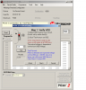
When i click ‘Test» to turn on Vdd i get result 3,5V.Although i set 4,5V.
Message: «Test failed. The Vdd result is low.The target circuit may be pulling toomuch current from Vdd or there may be too much capacitance on Vdd».
Although i disconnected device from PICKIT.
May be damage PICKIT?
Test failed for all Vdd. Only 3,2V.
post edited by sensor1976 — 2014/02/12 05:54:31
Ian.M
![]()
Super Member
- Total Posts : 13274
- Reward points : 0
- Joined: 2009/07/23 07:02:40
- Location: UK
- Status: offline
Re:PICkit 2 VDD and VPP voltage level errors
2014/02/12 06:34:56
(permalink)
Genuine PICkit 2 or clone?
You can pop the housing and check the PICkit 2’s intenal supply voltage at the ICSP connector pads for its internal PIC.
See teardown photos [here].
J1 pin 2 should be +5.00V +/- 0.25V, and is USB VBUS from your PC.
J1 pin 3 is 0V (Vss)
If the 5V is in tolerance, the PICkit 2 is faulty. What you do then depends on who made it.
If the 5V is low by more than 0.25V, try another USB cable and a different USB port.
post edited by Ian.M — 2014/02/12 06:42:00
scasis
![]()
Super Member
- Total Posts : 121
- Reward points : 0
- Joined: 2011/01/07 01:18:59
- Location: 0
- Status: offline
Re:PICkit 2 VDD and VPP voltage level errors
2014/02/12 13:21:01
(permalink)
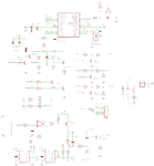
As You can see on schematic diagram in user guide of PICkit2 the +5V_USB, the voltage on USB V+ connector going to source of Q1. The voltage on drain of Q1 can be as high as on it’s source. If Vdd_TGT is switched on with P part of U5 the voltage on pin 4 of U5 can be as high as +5V_USB. Pin 4 of U5 connected to pin 2 of ICSP connector by a Schottky diode dropping 0.2 .. 0.25V. So maximum output voltage on Vdd_TGT pin of ICSP connector is 4.75V.
Ian.M
![]()
Super Member
- Total Posts : 13274
- Reward points : 0
- Joined: 2009/07/23 07:02:40
- Location: UK
- Status: offline
Re:PICkit 2 VDD and VPP voltage level errors
2014/02/12 13:29:00
(permalink)
@scasis: I was suggesting checking internal voltages at J1, not external voltages at J3
sensor1976
![]()
New Member
- Total Posts : 9
- Reward points : 0
- Joined: 2013/11/11 04:10:26
- Location: 0
- Status: offline
Re:PICkit 2 VDD and VPP voltage level errors
2014/02/13 02:33:54
(permalink)
scasis
As You can see on schematic diagram in user guide of PICkit2 the +5V_USB, the voltage on USB V+ connector going to source of Q1. The voltage on drain of Q1 can be as high as on it’s source. If Vdd_TGT is switched on with P part of U5 the voltage on pin 4 of U5 can be as high as +5V_USB. Pin 4 of U5 connected to pin 2 of ICSP connector by a Schottky diode dropping 0.2 .. 0.25V. So maximum output voltage on Vdd_TGT pin of ICSP connector is 4.75V.
I use genuine PICKIT2. Were i can find schematic diagram?When i launch PICkit 2 v2.61 the LED «Busy» is flashing and menu «PicKit error» appears.For long time i don’t programming by PICKITand used PICKIT as a power supplier for MCU. But when i wanted programm PIC16F877A PICKIT inform about error
Ian.M
![]()
Super Member
- Total Posts : 13274
- Reward points : 0
- Joined: 2009/07/23 07:02:40
- Location: UK
- Status: offline
Re:PICkit 2 VDD and VPP voltage level errors
2014/02/13 03:01:05
(permalink)
The schematic is in the user guide (appendix B). However I strongly recommend you raise a support ticket before attempting repair yourself if it is anything more than a dry joint on the USB or ICSP connectors. Microchip have a habit of being very very helpful — even if its out of warranty and you think the problem is your fault.
Add new support Ticket is [here]. When it tells you to type the first three characters to populate the list, its far easier to type the full product code: PG164120 ![]()
Содержание
- [SOLVED] Problem with my DIY Pickit2
- Plateau
- Plateau
- wp100
- jayanth.devarayanadurga
- wp100
- Plateau
- Plateau
- wp100
- Plateau
- Plateau
- wp100
- Attachments
- Plateau
- Plateau
- Pickit 2 VPP Voltage Level error
- nachum
- Attachments
- Wp100
- nachum
- blueroomelectronics
- Wp100
- nachum
- Wp100
- be80be
- nachum
- Attachments
- Vizier87
- nachum
- Attachments
- Wp100
- nachum
- Wp100
- nachum
- Wp100
- Attachments
- colin55
- nachum
- Attachments
- nachum
- nachum
[SOLVED] Problem with my DIY Pickit2
Plateau
Junior Member level 3

Hello, folks, are you all ok?
I’m facing a problem with my DIY Pickit 2 clone made by me. I’ve followed the steps from these references:
. and I’ve made some changes in layout (I put the most part of resistor in vertical position and added an external power supply for debugging).
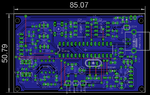
After solving some problems with the bootloader, now the problem is about VDD voltage level. When I connect the USB cable on the board, the Pickit2 is recognized by PC but the Pickit2 Software 2.61v always shows me this message: Pickit2 VDD voltage level error. Check target and retry operation.
If I plug the external power supply on, the VDD voltage level error stops and the Pickit2 works perfectly.
Well, I wouldn’t like to use the external power supply all the time.
Could anybody help me?
Plateau
Junior Member level 3
Hello, lijoppans, how are you?
The modified schematics are in my first post. My PCB was created by modifying this Reference for using «normal» electronic parts (not SMD).
Well. I’ll take a look on the reference gave by you.
Thanks in advance,
wp100
Advanced Member level 5

Looks like you have built a very close copy of the full Pk2, whereas most diy versions are a lot simpler without the eeproms etc.
You say the Pk2 works fine on an external psu , but you do not say what is connected to the Pk2, just a chip to be programmed or to a full circuit board ?
As I am sure you know, you must have the correct circuitry on your board if its to be used for ICSP.
Also assume you are using Pk2 V2.61 program rather than direct from MPlab.
Have you gone into the Tools, Troubleshooting section and run those tests ?
I would first get the Pk2 working using V2.61 with just a Pic chip connected directly to it with no external circuitry or psu and get that sorted out properly.
To me it sounds like you have a fault in either the pk2 +5v rails or something on your external board, which just using a pic chip shoulsd soon eliminate.

jayanth.devarayanadurga
Banned
Can you please zip and post your eagle .sch and .brd files?
wp100
Advanced Member level 5
Please show me the modified schematics. 2.
I made a Pickit2 clone. It can’t program 3.3V devices
Yes you can, I made a pk2 with a fixed 5v rail like yours.
You can do it two ways.
1. Apply 3v3 to the target chip /circuit before you power on the PK2, with the circuit like yours it will sense the 3v3 on the chip and turn off the +5v.
( just make sure Pk2 Vdd target is switched off)
2. The safer way I prefer, is to fit a 3v3 regulator on the +5v rail where the usb connector comes in so the whole PK2 circuitry is run on 3v3.
( I use the standard pic18F2550, not the LF version, and its programmed 18LF and Pic24 chips at 3v3 without problems.
Plateau
Plateau
Junior Member level 3
Hello, folks, are you al ok?
First of all, merry christmas.
I got mad due to the last problem and so I decided to make another PCB using all the files from the first reference (https://www.circuitvalley.com/2011/. howComment=1356263781754#c1820552152028921641).
My PCB seems ok, but now I’m facing another problem (well. I’m thinking I’m not lucky. haha).
When I plug the USB cable, the board is recognized but when I open the Pickit 2 Software 2.61v it gives me a VPP voltage level error (as you can see below)
**broken link removed**
If I go ahead through Troubleshooting, the first stage goes ok (VDD test, as you can see below).
But in VPP test, the Troubleshooting gives me this error:
In the last test (PGD and PGC) everything goes ok.
Well. I dont know what can I do. I realized a strange fact: if I remove the 47µF capacitor, this error (VPP Short circuit) does not happen, but the VPP voltage is too crazy (sometimes is 13v, sometimes is 2v). The voltage through BAT54 diode is 12.2 volts when I make VPP test. Thus, I think the «DC-DC converter» is ok.
Tomorrow I will try to replace all transistors (2N3904 and 2N3906), except BD140 and I hope this problem can be solved.
If somebody has any idea, feel free for helping me. haha
Thanks in advance, folks.
wp100
Advanced Member level 5
Well. I dont know what can I do. I realized a strange fact: if I remove the 47µF capacitor, this error (VPP Short circuit) does not happen, but the VPP voltage is too crazy (sometimes is 13v, sometimes is 2v). The voltage through BAT54 diode is 12.2 volts when I make VPP test. Thus, I think the «DC-DC converter» is ok.
Tomorrow I will try to replace all transistors (2N3904 and 2N3906), except BD140 and I hope this problem can be solved.
If somebody has any idea, feel free for helping me. haha
Thanks in advance, folks.
Its interesting that you do not have the +5v error on this build, though are your tests done with anything connected to the Pk2 ?
One of the first things the Pk2 software does is check the +5v and +12v lines and gives an error if things are not right.
You may have your transistors the wrong way round, its important you verify the pinout for the ones you bought, they can, but not often, vary in pinout from one manufacturer to another.
The 47uf is an integral part of the charge pump at it will not work without it.
No mention of a BAT54 in that link you show ? — assume its used instead of T2 ?
Have you substituted any other parts ?
If you are getting a proper 12v on your meter during the vpp test then perhaps look at the vpp feedback line r10/r11, thats what the program uses to detect is vpp is ok
Plateau
Plateau
Junior Member level 3
Hiho, wp100, are you ok?
I’ll answer these questions using the quote tool to simplify.
All my tests I’ve done without any device connected to the Pk2.
I realized in this SCH there are 3 transistors placed mirrored on the PCB. Please, take a look in Q4 , Q6 (both 2N3906) and T5 (2N3904). Yesterday, I replaced all of these transistors and I put others removed from electronic scrap. Today I’ve bought a new parts and I’m going to replace them later.
Huuuuum. The mistery is why Pk2 does not detect Short Circuit when I remove this capacitor. Too crazy haha.
I’ve found some BAT46 and BAT54 at home and so, I’ve replaced T2 for security. Furthermore, I replaced a 2N3904 to BC548 (respecting the pinout) and a 2N3906 to BC557 (respecting the pinout). but today later I’ll replace all transistors for new parts.
On the BAT54 cathode there is 12.2v and vpp feedback line there is 4.44v. Maybe this value can be higher than necessary but I think it’s correct.
One more time thank you so much, wp100.
wp100
Advanced Member level 5
Sound like the classic build problem, replacing so many parts you begin to wonder which are good and which are bad.
You can often get a chain reaction where one part damages the next and so on.
Although making a new pcb seems the right way, its often worth using all new parts to eliminate anything suspect.
Using substitute parts you must be sure they are suitable. You are using a 680 or 470uh choke ?
The project you show looks a very thorough presentation so have little reason to doubt that its a good proven design.
However its almost a full copy of the Pk2, and its often said you might find it quicker and cheaper to buy a Pk2 or Pk3 than trying to build your own.
Many PK2 designs shown in the forum are much simpler 4 transistor versions.
Perhaps you might be better trying one of those ?
Below is my diagram which works fine, though I hand wired it, but if you search this forum you will find similar designs with a circuit board layout.
I built it as back for my purchased Microchip Pk2
Attachments
Plateau
Plateau
Junior Member level 3
Sound like the classic build problem, replacing so many parts you begin to wonder which are good and which are bad.
You can often get a chain reaction where one part damages the next and so on.
Although making a new pcb seems the right way, its often worth using all new parts to eliminate anything suspect.
Using substitute parts you must be sure they are suitable. You are using a 680 or 470uh choke ?
The project you show looks a very thorough presentation so have little reason to doubt that its a good proven design.
However its almost a full copy of the Pk2, and its often said you might find it quicker and cheaper to buy a Pk2 or Pk3 than trying to build your own.
Many PK2 designs shown in the forum are much simpler 4 transistor versions.
Perhaps you might be better trying one of those ?
Below is my diagram which works fine, though I hand wired it, but if you search this forum you will find similar designs with a circuit board layout.
I built it as back for my purchased Microchip Pk2
Hiho, wp100, are you ok?
Thank you so much for helping me.
I’m making this Pk2 because here in Brazil it is a little bit expensive and I need to program some 3.3v PICs.
Could you think whether I change all transistors and choke, everything is going to be ok? By the way, at the first moment I’ve used a 1.5mH inductor (the first PCB who only works with external power supply) but I’ve found a 660uH and 1mH at home.
Another strange fact is when I use the 1mH or 1.5mH inductor a little noise is produced by inductor during VPP test but nothing happen with the 660uH inductor.
Источник
Pickit 2 VPP Voltage Level error
nachum
New Member
Hi
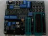
I bought a MINI KIT2 for programming. But when I try to program I get a message on the voltage level on VPP is lower than that message «Pickit 2 VPP Voltage Level error. Check target and retry operation.» . Any idea what could be done to resolve the problem.
I checked with a FLUKE the VPP showed me just 1+- volt.
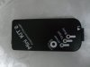
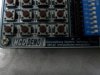
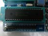
Attached pictures of programmer And the development board kit.
Thank you for your help
Attachments
Wp100
Well-Known Member
Not familiar with that dev board, but it looks like a far east Pickit2 clone.
I would first prove that the Mini Kit2 was working ok by simply putting your 16F chip in a breadboard etc and connecting short 5 wires to the programmer and first see if it can recognise the chip and then program.
The results of that should show what the next step is.
nachum
New Member

blueroomelectronics
Well-Known Member
Wp100
Well-Known Member
You should connect the two —
pin 1 VPP . 1
pin 32 & 11 + Vss . 2
pin 31 & 12 — Gnd . 3
pin 40 Data. 4
pin 39 Clock . 5
kit2 pin 6 not used , see the Microchip Pickit2 Help — User Manual for helpful info and trouble shooting is this does not work.
nachum
New Member
Wp100
Well-Known Member
Just need to establish some facts.
The 16F877, did that come preprogrammed with some sample led flashing progam for the dev board, if so, did it work on the dev board OK ? — Does it still work on the dev board ok ?
Your first attempt to program was with the 16F in the dev board zip socket and the minkkit2 plugged into the dev board ?
The attempt you have just done was in a breadboard with nothing else connected to the 16F and the wires between the two not longer that 150mm / 6″ ?
Do you have any other pic chips to hand ?

be80be
Well-Known Member
nachum
New Member
Attachments

Vizier87
Active Member
You’re sure? That is the problem then, USB output for Vpp to GND is around 5V. Check that from the USB output of your PC (it is USB connected ain’t it?) according to this:
**broken link removed**
Figure out the problem from that point, USB ain’t gonna be the problem, probably some short-circuit problems you overlooked.
nachum
New Member
Attachments
Wp100
Well-Known Member
If your last Vpp test was done with nothing connected to your Mini Kit2, and the Vdd looks ok, then it would seem you have a faulty unit and it needs returning to your supplier.
Is it a far east mail order unit ?
Internally they are smd devices and little you can do to them.
The reason I asked earlier about if you had run any demo on the dev board was to try and establish if that board was also ok, particularly the connections to pin1 the Mclre / Vpp pin.
nachum
New Member
Wp100
Well-Known Member
The Troubleshooting via the Pickit2 program must be intially done, as the opening screen states, with nothing connected to it other than your test meter wires.
So with the Minikit2 plugged into the usb lead and the output connector totally empty, connect your meter + lead to Vpp pin 1 and your meter — lead to pin 3 — your meter should be set to the dc volts range.
Do you get anything near 12v being shown ?
Also try the +5v Vdd again.
nachum
New Member
Wp100
Well-Known Member
Well even if you test it without the Fluke connected it should still show 12v on the diagnostic screen — looks like you have been unlucky and got a duff one.
Back to the suppliers then.
Attachments
colin55
Well-Known Member
nachum
New Member
How do I see 11+ volts? the USB is 5 volts.
I get an error vpp
Attachments

nachum
New Member
nachum
New Member
Could be that the PICKIT not know to program the PIC16F877??
link —http://cgi.ebay.com/DIY-PICKIT-2-PICKIT2-Microchip-PIC-Programmer-Debugger_W0QQitemZ390148784464QQcmdZViewItemQQptZBI_Electrical_Equipment_Tools?hash=item5ad6ae0150
Current PICkit 2 Programming Support (Mar 2007) Bold font indicates new parts supported in Application v2.20 and device file v1.20
PICkit 2 MPLAB 7.51 & 7.52 Support
Debugging & Programming
PIC12F683*
PIC16F684*, 685*, 687*, 688*, 689*, 690*
PIC16F883, 884, 886, 887
PIC16F913, 914, 916, 917, 946
These devices require an ICD header board to enable debugging with them Programming only
PIC12F508, 509, 510
PIC12F675
PIC16F505, 506
For the most current MPLAB support information, see Readme for PICkit 2 in the “Readmes” subdirectory of “MPLAB IDE.”
(Typically C:Program FilesMicrochipMPLAB IDEReadmes)
Notice: (please read this carefully for some often asked questions)
1 Device Support List (For reference only) (IDE 7.62, for latest version please check your readme file)
1.1 Debugger — Full Support
PIC16F690*
PIC16F884
PIC16F887
PIC16F883
PIC16F886
PIC16F917
1.2 Debugger — Beta Support
PIC12F629*
PIC16F627A*
PIC16F737
PIC16F874A
PIC16F628A*
PIC16F747
PIC16F876
PIC16F630*
PIC16F767
PIC16F876A
PIC16F631*
PIC16F777
PIC16F877
PIC16F636*
PIC16F785*
PIC16F877A
PIC16F648A*
PIC16F818
PIC16F88
PIC16F676*
PIC16F819
PIC16F882
PIC16F677*
PIC16F87
PIC16F913
PIC16F684*
PIC16F870
PIC16F914
PIC16F685*
PIC16F871
PIC16F916
PIC16F687*
PIC16F872
PIC16F946
PIC16F688*
PIC16F873
PIC16HV785*
PIC18F1220
PIC18F2682
PIC18F6310
PIC18F1230+
PIC18F2685
PIC18F6390
PIC18F1320
PIC18F4220
PIC18F6410
PIC18F1330+
PIC18F4221
PIC18F6490
PIC18F2220
PIC18F4320
PIC18F6520
PIC18F2221
PIC18F4321
PIC18F6525
PIC18F2320
PIC18F4331
PIC18F6527
PIC18F2321
PIC18F4410
PIC18F6585
PIC18F2331
PIC18F442
PIC18F6620
PIC18F2410
PIC18F4420
PIC18F6621
PIC18F242
PIC18F4423
PIC18F6622
PIC18F2420
PIC18F4431
PIC18F6627
PIC18F2423
PIC18F4450
PIC18F6628
PIC18F2431
PIC18F4455
PIC18F6680
PIC18F2450
PIC18F4458
PIC18F6720
PIC18F2455
PIC18F448
PIC18F6722
PIC18F2458
PIC18F4480
PIC18F6723
PIC18F248
PIC18F4510
PIC18F8310
PIC18F2480
PIC18F4515
PIC18F8390
PIC18F2510
PIC18F452
PIC18F8410
PIC18F2515
PIC18F4520
PIC18F8490
PIC18F252
PIC18F4523
PIC18F8520
PIC18F2520
PIC18F4525
PIC18F8525
PIC18F2523
PIC18F4550
PIC18F8527
PIC18F2525
PIC18F4553
PIC18F8585
PIC18F2550
PIC18F458
PIC18F8620
PIC18F2553
PIC18F4580
PIC18F8621
PIC18F258
PIC18F4585
PIC18F8622
PIC18F2580
PIC18F45K20
PIC18F8627
PIC18F2585
PIC18F4610
PIC18F8628
PIC18F25K20
PIC18F4620
PIC18F8680
PIC18F2610
PIC18F4680
PIC18F8720
PIC18F2620
PIC18F4682
PIC18F8722
PIC18F2680
PIC18F4685
PIC18F8723
1.3 Programmer — Full Support
PIC12F510
PIC16F506
PIC16F88
PIC16F887
PIC16F684
PIC16F883
PIC16F917
1.4 Programmer — Beta Support
PIC12F508
Источник
Вот пример, извините если мс древняя, что есть.
Все просто вроде- 5 выводов, подавать питание на МК или с Пикита2 идет уже нужное?
И кстати куда его подавать? Нет такого контакта Vdd для программирования.
Вобщем при подключении к МК — прога Pickit2 Programmer выдает ошибку :
«Pickit2 VPP voltage level error. Check target & retry оператион»
причем просто при подключении к МК.
Вообще еще ни разу не видел в окошке программы какие-то коды или цыфры.
И что за вывод PGM — судя по даташиту это «низковольтный тактовый сигнал включения(?)» простите за мой французский.
Ну и сразу скажу — пикит2 рабочий, прошивает, МК (микроконтролёр) который щас хочу прошить научиться — тоже полностью рабочий, это целиком собранное устройство.
Я хочу научиться прошиватьпонимать сам процесс, поскольку полный нуль в этом деле. Поэтому взял в аренду рабочую плату «для опытов». Проц стоит PIC18LF252, что для опытов я думаю не принципиально.
ЗЫ. Попробовал другую плату — и наконец-то заработало! Прочитал прошивку, сохранил — щас надо как-то открыть ее. Пробую программу MPLAB IDE версии 8.46. — но она не может открыть, вообще ни один файл!
Да чтож за дело то это такое…
Пишет «системе не удается найти указанный путь», да это ни в какие рамки не лезет!!! Издеваются!
В чем трабла — не пойму. Как-то же должно открываться, для изменений или переделки.
Сам писать прошивки не могу, хочу попробовать в теле прошивки изменить какие-то данные и посмотреть к чему и как это приводит.
Например время горения дисплея не 5 сек, а чтобы загорался при нажатии и угасал тоже при нажатии. кнопки. То бишь методом тыка пробовать и смотреть на результат.
Видел как написаны прошивки, это нужно с этим работать чтобы писать подобные вещи. Да и отучиться не мешало бы. Учиться не поздно, статей много, желание есть. И задумки тоже есть.
КСтати, если одна плата не отвечает на запросы программера, а вторая включилась — может это зависит как раз от чипа — в первой плате стоит 18LF252, а во второй — уже 18F2520. Чип-то новее!
Или какая-то защита от чтения? Тоже не знаю…
Изменено 3 Февраля, 2016 в 17:52 пользователем mitrych
Skip to main content
![]()
![]()
Welcome to our site!
Electro Tech is an online community (with over 170,000 members) who enjoy talking about and building electronic circuits, projects and gadgets. To participate you need to register. Registration is free. Click here to register now.
-
Welcome to our site! Electro Tech is an online community (with over 170,000 members) who enjoy talking about and building electronic circuits, projects and gadgets. To participate you need to register. Registration is free. Click here to register now.
-
Electronics Forums
-
Microcontrollers
You should upgrade or use an alternative browser.
Pickit 2 VPP Voltage Level error
-
Thread starternachum
-
Start dateFeb 17, 2010
- Status
- Not open for further replies.
-
#1
I bought a MINI KIT2 for programming. But when I try to program I get a message on the voltage level on VPP is lower than that message «Pickit 2 VPP Voltage Level error. Check target and retry operation.» . Any idea what could be done to resolve the problem.
I checked with a FLUKE the VPP showed me just 1+- volt.
Attached pictures of programmer And the development board kit.
Thank you for your help
Attachments
-
#2
Not familiar with that dev board, but it looks like a far east Pickit2 clone.
I would first prove that the Mini Kit2 was working ok by simply putting your 16F chip in a breadboard etc and connecting short 5 wires to the programmer and first see if it can recognise the chip and then program.
The results of that should show what the next step is.
-
#3
What connections should I do ?
i work whit pic16f877a

-
#4
-
#5
You should connect the two —
16F877a…………………..Pickit2
pin 1 VPP …………………..1
pin 32 & 11 + Vss ……… 2
pin 31 & 12 — Gnd ……….3
pin 40 Data…………………4
pin 39 Clock ……………….5
kit2 pin 6 not used , see the Microchip Pickit2 Help — User Manual for helpful info and trouble shooting is this does not work.
-
#6
I connected the micro to the PICKIT 2.
Like you said
pin 1 VPP …………………..1
pin 32 & 11 + Vss ……… 2
pin 31 & 12 — Gnd ……….3
pin 40 Data…………………4
pin 39 Clock ……………….5
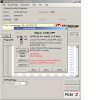
I check with PICkit 2 v2.61 and i Received «Pickit 2 VPP Voltage Level error. Check target and retry operation»
-
#7
Just need to establish some facts.
The 16F877, did that come preprogrammed with some sample led flashing progam for the dev board, if so, did it work on the dev board OK ? — Does it still work on the dev board ok ?
Your first attempt to program was with the 16F in the dev board zip socket and the minkkit2 plugged into the dev board ?
The attempt you have just done was in a breadboard with nothing else connected to the 16F and the wires between the two not longer that 150mm / 6″ ?
Do you have any other pic chips to hand ?

-
#8
pulled low it should be pulled to Vdd with a 10k resistor
Last edited: Feb 17, 2010
-
#9
Right now I could not do anything.
I always get an error message on the problem of voltage VPP.
I downloaded the software that checks voltage programmer. And there I get no voltage on VPP.
There could be a problem with the programmer or I did not connect properly??
Attachments

-
#10
I checked with a FLUKE the VPP showed me just 1+- volt.
You’re sure? That is the problem then, USB output for Vpp to GND is around 5V. Check that from the USB output of your PC (it is USB connected ain’t it?) according to this:
**broken link removed**
Figure out the problem from that point, USB ain’t gonna be the problem, probably some short-circuit problems you overlooked.
Last edited: Feb 17, 2010
-
#11
But when I try to Check Communication i get an error message on VPP.
I attached pictures.
Attachments
-
#12
If your last Vpp test was done with nothing connected to your Mini Kit2, and the Vdd looks ok, then it would seem you have a faulty unit and it needs returning to your supplier.
Is it a far east mail order unit ?
Internally they are smd devices and little you can do to them.
The reason I asked earlier about if you had run any demo on the dev board was to try and establish if that board was also ok, particularly the connections to pin1 the Mclre / Vpp pin.
-
#13
I bought the programmer in China
If I did not connect the pic16f877a to PICKIT 2 Which result I should get When I check the VPP ??
-
#14
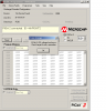
The Troubleshooting via the Pickit2 program must be intially done, as the opening screen states, with nothing connected to it other than your test meter wires.
So with the Minikit2 plugged into the usb lead and the output connector totally empty, connect your meter + lead to Vpp pin 1 and your meter — lead to pin 3 — your meter should be set to the dc volts range.
Do you get anything near 12v being shown ?
Also try the +5v Vdd again.
-
#15
vdd=5v
vpp=0v
-
#16
Well even if you test it without the Fluke connected it should still show 12v on the diagnostic screen — looks like you have been unlucky and got a duff one.
Back to the suppliers then…
Attachments
-
#17
-
#18
How do I see 11+ volts? the USB is 5 volts.
I get an error vpp
Attachments
-
#19
So I installed the software PICkit 2 v2.61 and saw that PICKIT 2 volts on VPP.
-
#20
link —http://cgi.ebay.com/DIY-PICKIT-2-PICKIT2-Microchip-PIC-Programmer-Debugger_W0QQitemZ390148784464QQcmdZViewItemQQptZBI_Electrical_Equipment_Tools?hash=item5ad6ae0150
Current PICkit 2 Programming Support (Mar 2007) Bold font indicates new parts supported in Application v2.20 and device file v1.20
PICkit 2 MPLAB 7.51 & 7.52 Support
Debugging & Programming
PIC12F683*
PIC16F684*, 685*, 687*, 688*, 689*, 690*
PIC16F883, 884, 886, 887
PIC16F913, 914, 916, 917, 946
These devices require an ICD header board to enable debugging with them Programming only
PIC12F508, 509, 510
PIC12F675
PIC16F505, 506
For the most current MPLAB support information, see Readme for PICkit 2 in the “Readmes” subdirectory of “MPLAB IDE.”
(Typically C:Program FilesMicrochipMPLAB IDEReadmes)
Notice: (please read this carefully for some often asked questions)
1 Device Support List (For reference only) (IDE 7.62, for latest version please check your readme file)
1.1 Debugger — Full Support
PIC16F690*
PIC16F884
PIC16F887
PIC16F883
PIC16F886
PIC16F917
1.2 Debugger — Beta Support
PIC12F629*
PIC12F635*
PIC12F675*
PIC12F683*
PIC16F627A*
PIC16F737
PIC16F874A
PIC16F628A*
PIC16F747
PIC16F876
PIC16F630*
PIC16F767
PIC16F876A
PIC16F631*
PIC16F777
PIC16F877
PIC16F636*
PIC16F785*
PIC16F877A
PIC16F648A*
PIC16F818
PIC16F88
PIC16F676*
PIC16F819
PIC16F882
PIC16F677*
PIC16F87
PIC16F913
PIC16F684*
PIC16F870
PIC16F914
PIC16F685*
PIC16F871
PIC16F916
PIC16F687*
PIC16F872
PIC16F946
PIC16F688*
PIC16F873
PIC16HV785*
PIC16F689*
PIC16F873A
PIC16F716*
PIC16F874
PIC18F1220
PIC18F2682
PIC18F6310
PIC18F1230+
PIC18F2685
PIC18F6390
PIC18F1320
PIC18F4220
PIC18F6410
PIC18F1330+
PIC18F4221
PIC18F6490
PIC18F2220
PIC18F4320
PIC18F6520
PIC18F2221
PIC18F4321
PIC18F6525
PIC18F2320
PIC18F4331
PIC18F6527
PIC18F2321
PIC18F4410
PIC18F6585
PIC18F2331
PIC18F442
PIC18F6620
PIC18F2410
PIC18F4420
PIC18F6621
PIC18F242
PIC18F4423
PIC18F6622
PIC18F2420
PIC18F4431
PIC18F6627
PIC18F2423
PIC18F4450
PIC18F6628
PIC18F2431
PIC18F4455
PIC18F6680
PIC18F2450
PIC18F4458
PIC18F6720
PIC18F2455
PIC18F448
PIC18F6722
PIC18F2458
PIC18F4480
PIC18F6723
PIC18F248
PIC18F4510
PIC18F8310
PIC18F2480
PIC18F4515
PIC18F8390
PIC18F2510
PIC18F452
PIC18F8410
PIC18F2515
PIC18F4520
PIC18F8490
PIC18F252
PIC18F4523
PIC18F8520
PIC18F2520
PIC18F4525
PIC18F8525
PIC18F2523
PIC18F4550
PIC18F8527
PIC18F2525
PIC18F4553
PIC18F8585
PIC18F2550
PIC18F458
PIC18F8620
PIC18F2553
PIC18F4580
PIC18F8621
PIC18F258
PIC18F4585
PIC18F8622
PIC18F2580
PIC18F45K20
PIC18F8627
PIC18F2585
PIC18F4610
PIC18F8628
PIC18F25K20
PIC18F4620
PIC18F8680
PIC18F2610
PIC18F4680
PIC18F8720
PIC18F2620
PIC18F4682
PIC18F8722
PIC18F2680
PIC18F4685
PIC18F8723
1.3 Programmer — Full Support
PIC12F510
PIC12F675
PIC16F506
PIC16F88
PIC16F887
PIC16F684
PIC16F883
PIC16F917
PIC16F690
PIC16F884
PIC16F87
PIC16F886
1.4 Programmer — Beta Support
PIC12F508
PIC12F509
PIC12F629
PIC12F635
PIC12F683
PIC16F505
PIC16F716
PIC16F874
PIC16F627A
PIC16F737
PIC16F874A
PIC16F628A
PIC16F747
PIC16F876
PIC16F630
PIC16F767
PIC16F876A
PIC16F631
PIC16F777
PIC16F877
PIC16F636
PIC16F785
PIC16F877A
PIC16F648A
PIC16F818
PIC16F882
PIC16F676
PIC16F819
PIC16F913
PIC16F677
PIC16F870
PIC16F914
PIC16F685
PIC16F871
PIC16F916
PIC16F687
PIC16F872
PIC16F946
PIC16F688
PIC16F873
PIC16HV785
PIC16F689
PIC16F873A
PIC18F1220
PIC18F2682
PIC18F6310
PIC18F1230
PIC18F2685
PIC18F6390
PIC18F1320
PIC18F4220
PIC18F6410
PIC18F1330
PIC18F4221
PIC18F6490
PIC18F2220
PIC18F4320
PIC18F6520
PIC18F2221
PIC18F4321
PIC18F6525
PIC18F2320
PIC18F4331
PIC18F6527
PIC18F2321
PIC18F4410
PIC18F6585
PIC18F2331
PIC18F442
PIC18F6620
PIC18F2410
PIC18F4420
PIC18F6621
PIC18F242
PIC18F4423
PIC18F6622
PIC18F2420
PIC18F4431
PIC18F6627
PIC18F2423
PIC18F4450
PIC18F6628
PIC18F2431
PIC18F4455
PIC18F6680
PIC18F2450
PIC18F4458
PIC18F6720
PIC18F2455
PIC18F448
PIC18F6722
PIC18F2458
PIC18F4480
PIC18F6723
PIC18F248
PIC18F4510
PIC18F8310
PIC18F2480
PIC18F4515
PIC18F8390
PIC18F2510
PIC18F452
PIC18F8410
PIC18F2515
PIC18F4520
PIC18F8490
PIC18F252
PIC18F4523
PIC18F8520
PIC18F2520
PIC18F4525
PIC18F8525
PIC18F2523
PIC18F4550
PIC18F8527
PIC18F2525
PIC18F4553
PIC18F8585
PIC18F2550
PIC18F458
PIC18F8620
PIC18F2553
PIC18F4580
PIC18F8621
PIC18F258
PIC18F4585
PIC18F8622
PIC18F2580
PIC18F45K20
PIC18F8627
PIC18F2585
PIC18F4610
PIC18F8628
PIC18F25K20
PIC18F4620
PIC18F8680
PIC18F2610
PIC18F4680
PIC18F8720
PIC18F2620
PIC18F4682
PIC18F8722
PIC18F2680
PIC18F4685
PIC18F8723
* These devices require a header board to be able to debug the device. See the Header Board Specification (DS51292) for more information. This document is available in the “Downloads” section of the PICkit 2 web page.
- Status
- Not open for further replies.
Similar threads
![]()
-
Electronics Forums
-
Microcontrollers
-
This site uses cookies to help personalise content, tailor your experience and to keep you logged in if you register.
By continuing to use this site, you are consenting to our use of cookies.

Topic: Home built Pickit 2 not behaving normally. (Read 3389 times)
0 Members and 1 Guest are viewing this topic.
Hi All,
I am having a strange problem with a homebuilt PickIt2. It is wired just as MicroChip designed it, but I substituted a few parts to facilitate thru hole construction. I subbed a BS250P P channel MOSFET for the IRLML6402 and the Q2 part of U5, and a TN0702N3 for the Q1 part of U5. I also subbed a MCP6041 op amp for the MCP6001 op amp. The board is recognized by the PickIt2 v2.61 software. The problems are as follows:
1) When first plugged I get the error message bo that says «Pickit 2 VDD voltage level error. Check target and retry operation.» I get this error message whether a PIC is connected or not.
2) When I hit OK the PickIt 2 Programmer software runs and shows that a PickIt 2 was found and connected. Sometimes it finds a connected device, other times it doesn’t.
3) If it finds a device, pressing Erase or Blank Check brings up the VDD error box again, and then the software reports «No device detected».
When I run the troubleshooter, the following occurs:
Step 1 passes but I always have about .2V difference between what I set and what I read in the results box and on my DMM.
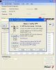
Step 2 Pressing «Test VPP» the first time gives me a «Test Failed: VDD Short Detected» error. I can see with my scope that the level is high, and I can measure around +12V with the DMM. If I press «Test VPP» a second time it reports that the test passed with a voltage reading close to what I get on my DMM. When I press «/MCLR On» the VPP level drops to 0.
Step 3 I can control the PGC and PGD lines during step 3 testing.
I feel that Step 2 is the main problem, but tracing my connections has shown no miswires. Plus if there was a miswire, just running the step a second time would not pass the test.
Did one of my substitutions break something?
Any ideas on how to get this working would be greatly appreciated.
Regards,
Mike

Logged
BS250P Rdson is 14 Ohms max, compared to 0.08 Ohms for the IRLML6402. This is at -10V Gate drive and the threshold is 3.5V max, so it’s probably even higher with 5V Gate drive.
Perhaps the extra resistance is slowing down +V_TGT rise time enough for the test to fail the first time. Without knowing what is acceptable it might be better to just use the correct parts (or close equivalents).
Logged
Hi Bruce,
Thanks for the quick response. I was trying to build this with all thru hole parts. Maybe I need to use both thru hole and surface mount?
Thanks for your time!
Regards,
Mike
Logged
These 2 well proven pk2 circuits using common through hole parts might help you locate your problem.
They do not use the variable Vdd, but all you need do is run the whole circuit at 3v3 is you want to program 3v3 chips.
Logged
Hi picandmix,
Thanks for those 2 schematics. I will investigate them.
Regards,
Mike
Logged
Hi picandmix,
Thanks for those 2 schematics. I will investigate them.
Regards,
Mike
You are welcome, they are 100% proven circuits, that second one being mine that I built as a backup to my original Microchip Pk2 in 2008, still works fine today 
Logged
Mike nailed it. The PICKIT2 checks for short circuit. If the expected target VDD is not met within a very short time, probably on order of 1 mS, it will take this as a user error of short circuit between Vdd and ground rail and turn off the power to prevent damage.
U5 also must be responsive. This part is even faster than the IRLML402. This is a dual trench power FET with sub 100mohm RDSon at only 4.5V and only 10nS turn on times. So you need to pay attention to all 3 of these FETs, but particularly to the 2 PFETs if you want to make this VDD error go away. But slower FETs will also slow the feedback loop and might potentially allow poorer regulation or oscillation under certain conditions.
I subbed all these FETs, on my own clones. But I used faster and cheaper FETs.
Maybe one of the biggest waste of money on the original parts list is the tantalum FET for Vpp generator. I dunno why that is there. It costs like 2 dollars. I use a cheap ceramic. My understanding is Vpp has a very wide range of acceptable voltage and does not need to be particularly accurate or stable, and the draw on it is very low.
« Last Edit: May 31, 2017, 11:22:06 pm by KL27x »
Logged
Hi KL27x,
Thanks for your response. I subbed thru hole parts for the SMT parts hoping that it would not degrade performance much. Anyway I was way wrong! So I have ordered the correct parts along with SOT23 to DIP and SSOT6 to DIP adapters. Damn adapters have a 6 week lead time.
I will report back to this forum once I receive and install the correct parts.
Thanks again for reading and lending your experience!
Regards,
Mike
Logged
I just searched for comparable thru hole transistors, thinking there would be some. Wow, who knew thru hole has been dead this long?
Logged
Hi KL27x,
Yeah I didn’t think it would be such a problem.
Oh well!
Regards,
Mike
Logged