One of the best Automation vendors all over the world is Siemens, this good reputation was not formed by chance, one of the main reasons for this reputation is its software programming environment TIA Portal (Totally Integrated Automation).
Table of contents
- Types of Software Faults
- Logic Error (Programming)
- Compiling Error (System)
- How to Deal with PLC Programming Faults?
- Steps to go Online through your PLC
- How to Deal with Compiling Errors in PLC?
The advantage of this program is the integration of all Siemens components, using this software you will be able to:
- Configuring the hardware of your project.
- Establishing the whole network of the system.
- Programming of PLC with different languages.
- Designing of SCADA & HMI systems.
- Simulation of your projects.
- Finally, the scope of our article that this software could really offer a great feature to ease the troubleshooting of your Automation system.
Types of Software Faults
The software faults or errors could be divided into two categories:
Logic Error (Programming)
These types of errors cause abnormal behavior and actions for the system, it is caused due to some programming mistakes, it could be wrong addressing of the I/O signals or it may be some mistakes with the ladder logic itself, the bad news that it should be detected by the programmer with himself the software will not be able to determine these types of errors where it is.
However, these errors could be traced by going online with the PLC and check the rungs as we will see.
Compiling Error (System)
On the other hand, we might find these errors which are caused by some programming mistakes that the compiler of the software can not accept it, the good news is that these errors are detected by the compiler of the software.
Also, we can use the Diagnostic buffer that saves all the events that happened with the PLC and it is really a great tool for troubleshooting.
Also Read: PLC Hardware Troubleshooting Steps
How to Deal with PLC Programming Faults?
These faults mostly occurred at the commissioning phase, as you just finished writing your code and you are going to try your logic with the real field.
It is very normal to find out some mistakes through your code, and the best way to overcome such a situation is to go online with the PLC.
Steps to go Online through your PLC
- The first thing that you need to do is connecting your PC/PG with the PLC through an Ethernet cable to establish the physical layer of the network.
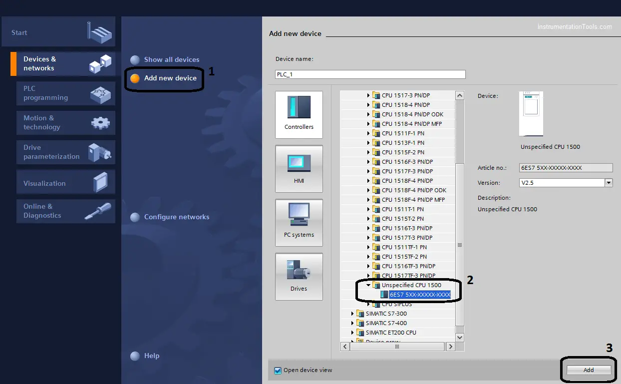
- Then you have to go through TIA Portal and open a new project and select unspecified 1500 CPU as shown in the next figure. (Note if you already know the CPU No. you can choose it directly)
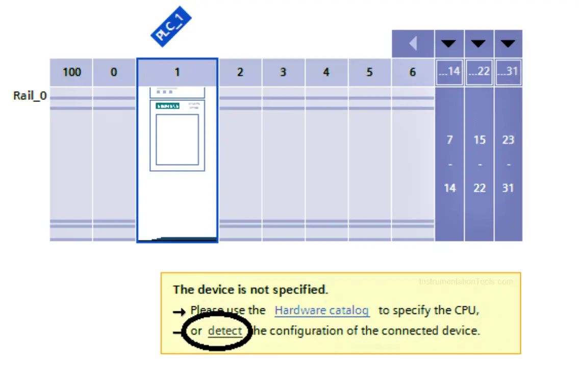
- The next step is to detect the hardware configuration of your station.
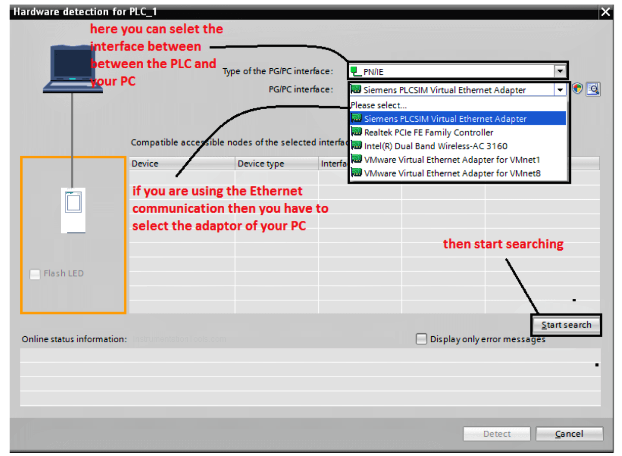
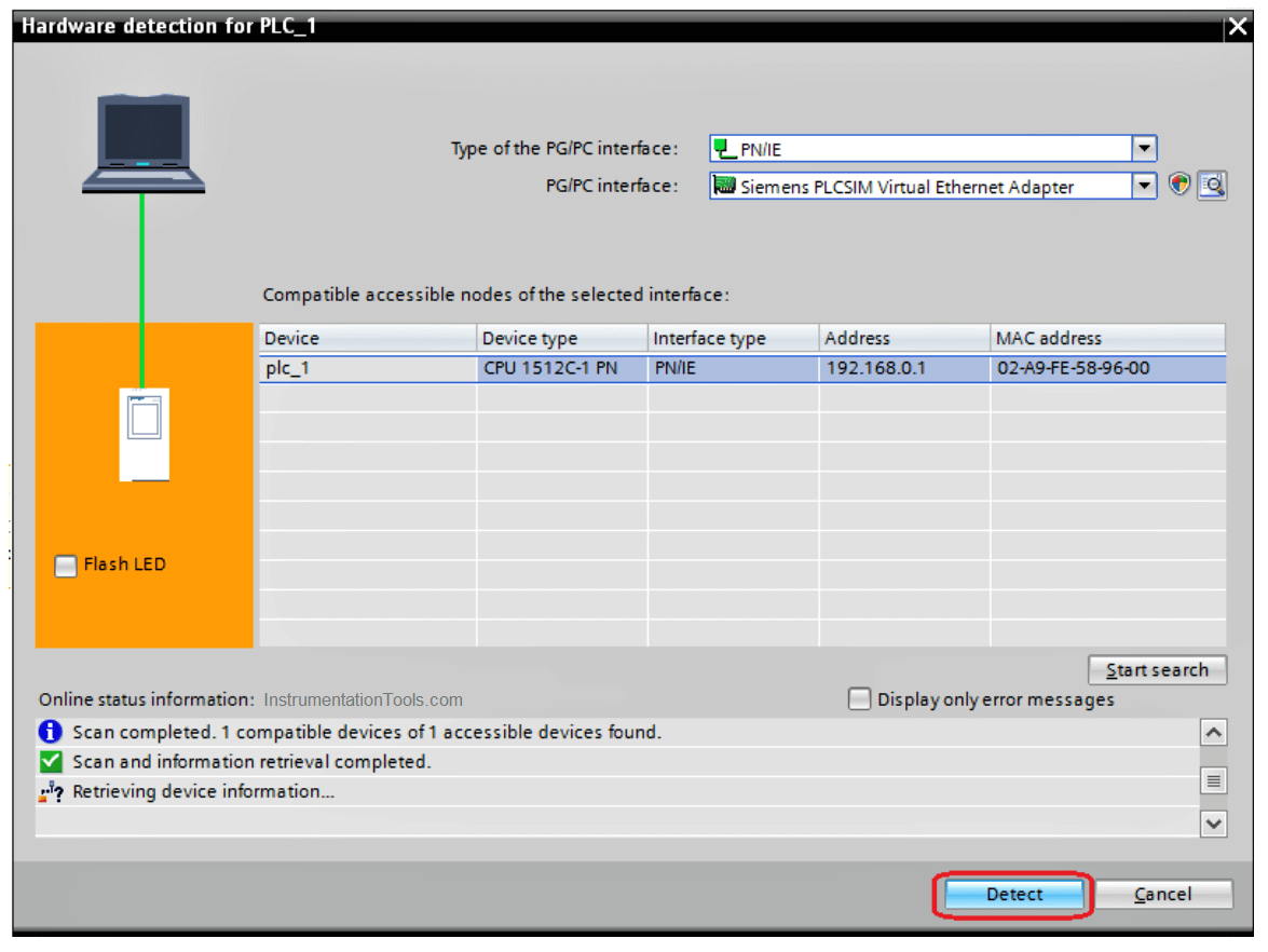
- If you are using an Ethernet connection make sure that the IP of the PLC and your PC at the same subnet, then after searching about the PLC select the device and press detect.
- Here and after selecting the PLC you have to go online with your code to see what is going into your logic visually, that would really help a lot to track the problem.
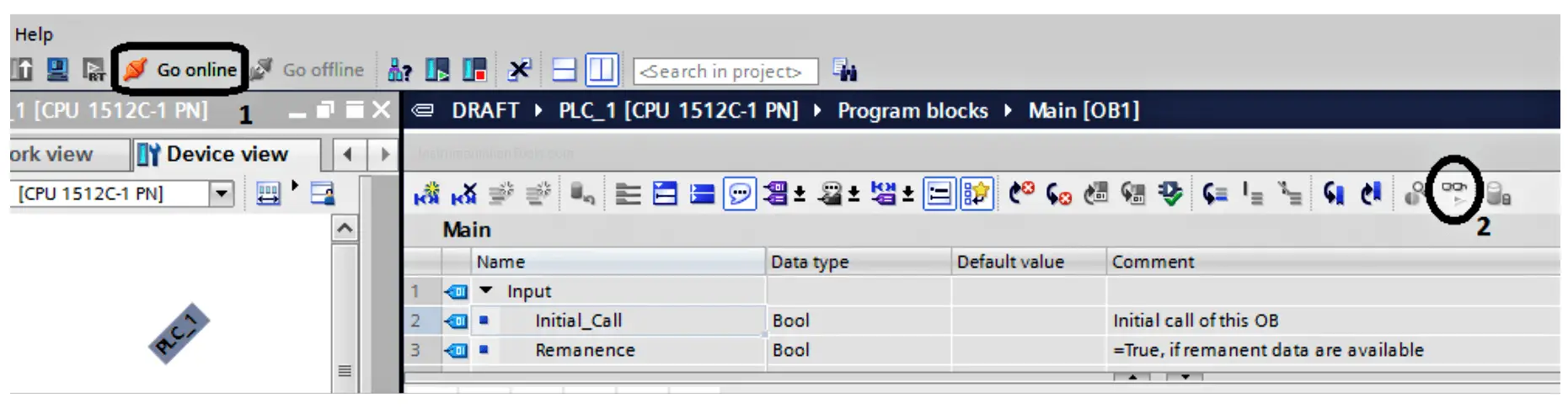
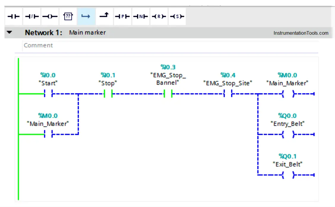
- Now we are online with our PLC to know why the process is not running even we are pressing on the start push button.
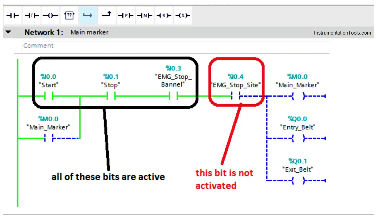
- As we can see it is too easy to trace the activated and deactivated bits from the ladder logic, the green bit is activated and the blue dashed one is not activated.
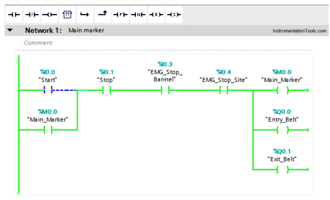
- After going to the Emergency stop at the site and activate it, now we can see all of the branch is correctly operated.
How to Deal with Compiling Errors in PLC?
By using the TIA portal software, it is too easy to identify and detect the compiling faults, as the program points at the errors by identifying a detailed location of the error.
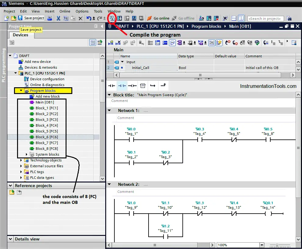
For the next figure, we can see a simple code that consists of some functions and the main OB, by compiling the code from the sign below, a compiling window will appear and it will check all the program networks to detect any type of errors.
Note: Before compiling the code, you have to ensure that you select the whole program blocks not just the main OB, that by pressing on the program blocks below that is shown with yellow color.
Here is the window that defines the type of the error and its detailed location, we can see that we have three compiling errors at Function (6) at Networks (1 & 2).
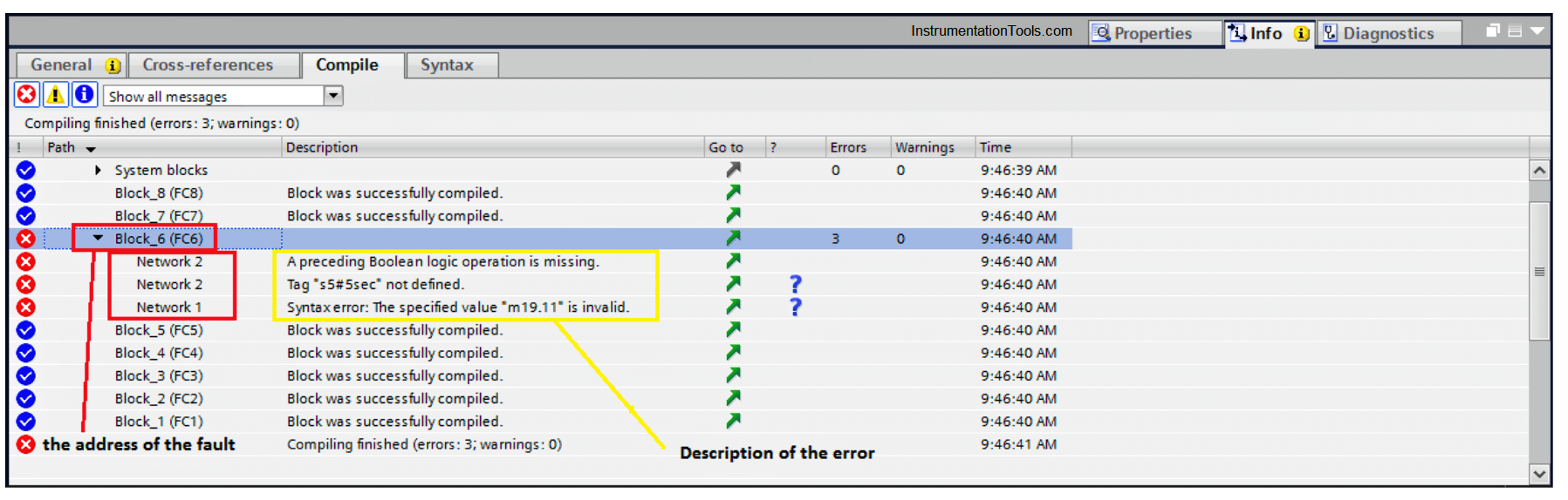
Notice that you can go to the invalid network manually or you just can click on the network and the function would open automatically and it will point to the faulty network.
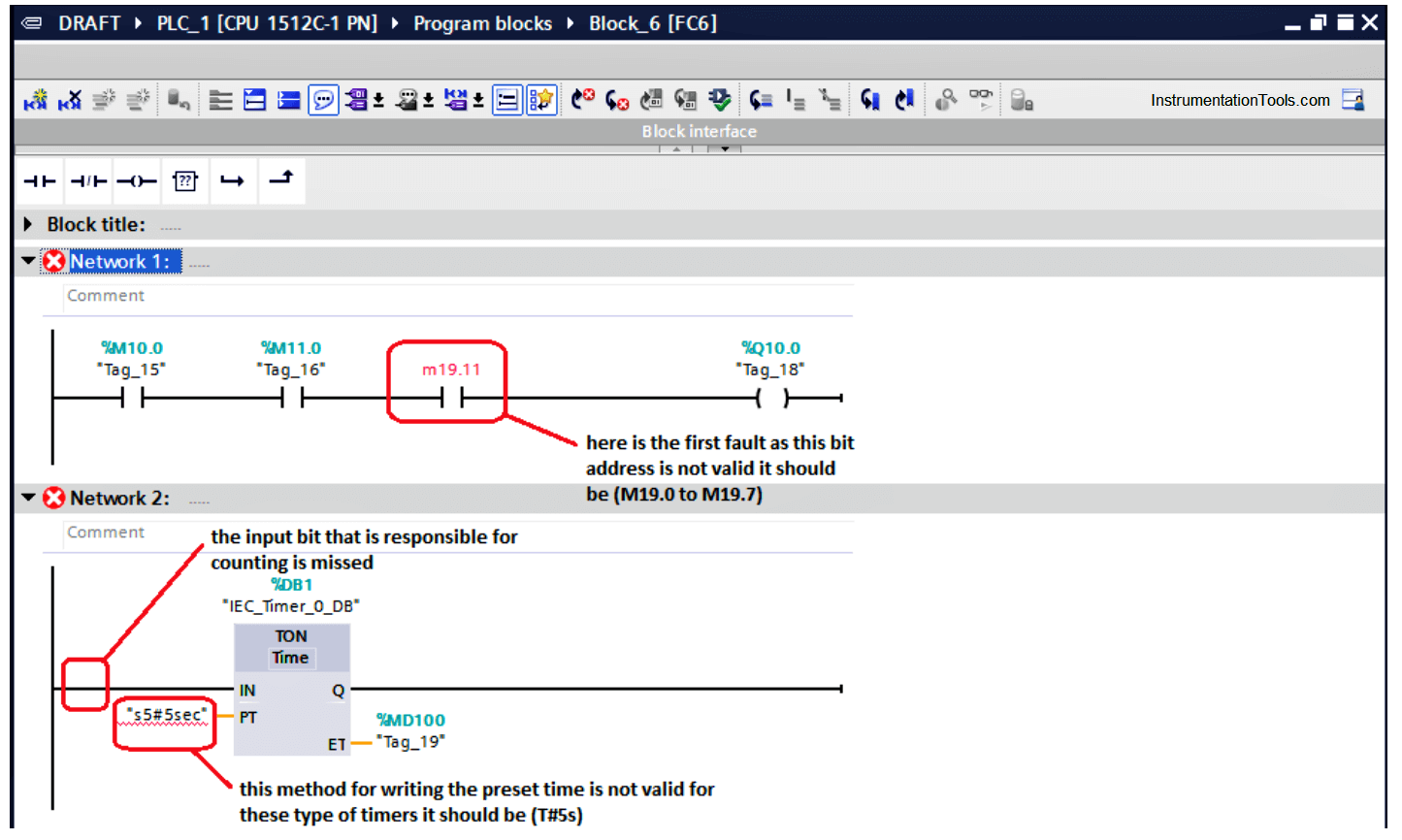
After going to the desired function, we will find the three faults as shown in the next figure:
- It is clear for us about the first fault that the byte (19) should have just eight bits so it can be addressed as M (19.0 – 19.1 – 19.2 – 19.3 – 19.4 – 19.5 – 19.6 – 19.7).
- Here for the second rung we can notice that there are two faults the first one is there is no an assigned input that would make the timer count.
There must be a bit at the timer input that is responsible for timer counting.
- Also, for the second rung you can notice the preset time is written into wrong way.
The right way to insert the preset time for such timers is that (T#5s)
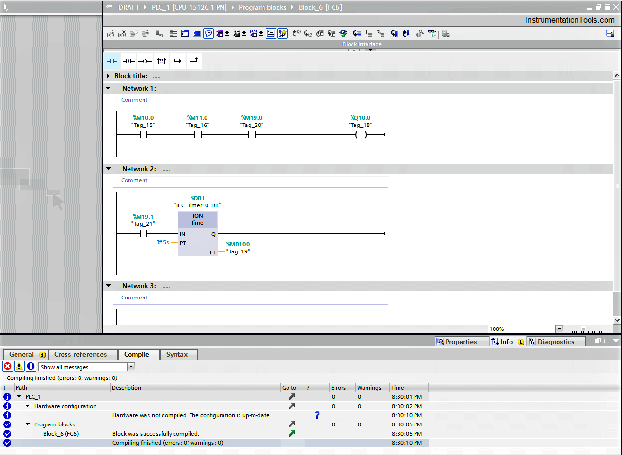
So, by editing our code and fixing the faults, we can compile it again to ensure that is healthy.
In the next article, we will discuss a very important tool that helps a lot with troubleshooting which is the Diagnostic Buffer so stay tuned and wait for it.
If you liked this article, then please subscribe to our YouTube Channel for Instrumentation, Electrical, PLC, and SCADA video tutorials.
You can also follow us on Facebook and Twitter to receive daily updates.
Read Next:
- Yokogawa DCS Tutorials
- PLC System Cabinet Health Checks
- Communication Protocols in PLC
- SFC Language in PLC Programming
- Difference between PLC and Computers
The PLC minor fault codes,
| Type | Code | Cause | Recovery Method |
| 1 | 15 | · A 1769 power supply is connected directly to the controller’s 1768 CompactBus, with an invalid configuration.
· The 1768 power supply powering the controller has failed. |
· Remove the power supply from the 1768 CompactBus and cycle power to the system.
· Replace the power supply. |
| 3 | 1 | Bus off condition. The connections between the controller and the I/O modules are broken. | Complete these steps to identify the source of the BUS OFF fault:
1. The number of local expansion modules in the project matches the number of modules that are physically installed in the system. 2. All mounting bases are locked and I/O modules are securely installed on mounting bases. 3. All 1734 POINT I/O modules are configured to use the Autobaud rate. If these steps do not remedy the fault condition, contact Rockwell Automation support. |
| 3 | 94 | The current RPI update of an I/O module overlaps with its previous RPI update. | Set the RPI rate of the I/O modules to a higher numerical value. Rockwell Automation recommends that the CompactLogix 5370 L2 and
CompactLogix 5370 L3 control systems do not run with Module RPI Overlap faults. |
| 3 | 100 | The potential exists for data integrity loss with the module because either or both of the input/output size > 16 bytes and the module does not support start and end integrity. | Recover methods:
· Decrease input/output sizes to <= 16 bytes which avoids data integrity loss concern. · Contact the module provider to inquire about a version that supports the start and end integrity function. |
| 4 | 4 | An arithmetic overflow occurred in an instruction. | Fix program by examining arithmetic operations (order) or adjusting values. |
| 4 | 5 | In a GSV/SSV instruction, the specified instance was not found. | Check the instance name. |
| 4 | 6 | In a GSV/SSV instruction, either:
· Specified Class name is not supported · Specified Attribute name is not valid |
Check the Class name and Attribute name. |
| 4 | 7 | The GSV/SSV destination tag was too small to hold all of the data. | Fix the destination or source so it has enough space. |
| 4 | 30 | Bad parameters passed through to the ASCII port. | Verify the ASCII configuration settings. |
| 4 | 35 | PID delta time 0. | Adjust the PID delta time so that it is > 0. |
| 4 | 36 | PID setpoint out of range. | Adjust the setpoint so that it is in range. |
| 4 | 51 | The LEN value of the string tag is greater than the DATA size of the string tag. | · Check that no instruction is writing to the LEN member of the string tag.
· In the LEN value, enter the number of characters that the string contains. |
| 4 | 52 | The output string is larger than the destination. | Create a new string data type that is large enough for the output string. Use the new string data type as the data type for the destination. |
| 4 | 53 | The output number is beyond the limits of the destination data type. | Either:
· Reduce the size of the ASCII value. · Use a larger data type for the destination. |
| 4 | 56 | The Start or Quantity value is invalid. | · Check that the Start value is between 1 and the DATA size of the Source.
· Check that the Start value plus the Quantity value is less than or equal to the DATA size of the Source. |
| 4 | 57 | The AHL instruction failed to execute because the serial port is set to no handshaking. | Either:
· Change the Control Line setting of the serial port. · Delete the AHL instruction. |
| 6 | 2 | Periodic task overlap.
Periodic task has not completed before it is time to execute again. |
Make changes such as simplifying programs, lengthening the period, or raising the relative priority. |
| 6 | 3 | Event task overlap.
Event task has not completed before it is time to execute again. |
Make changes such as simplifying programs, lengthening the period, raising the relative priority, or slowing the triggering event. |
| 7 | 49 | When the controller loads a project from nonvolatile memory, it logs this minor fault and sets the FaultLog object, MinorFaultBits attribute, bit 7. | Clear the fault. |
| 9 | 0 | Unknown error while servicing serial port | Contact Rockwell Automation Technical Support if the problem persists. |
| 9 | 1 | The CTS line is not correct for current configuration. | Disconnect and reconnect the serial port cable to the controller. Verify cabling is correct. |
| 9 | 2 | Poll list error.
A fault was detected with the DF1 master’s poll list, such as specifying more stations than the size of the file, specifying more than 255 stations, trying to index past the end of the list, or polling the broadcast address (STN #255). |
Check for the following errors:
· Total number of stations is greater than the space in the poll list tag. · Total number of stations is greater than 255. · Current station pointer is greater than the end of the poll list tag. · A station number greater than 254 was encountered. |
| 9 | 3 | The RS-232 DF1 Master Active Station Tag is unspecified. | Specify a tag to be used for the Active Station Tag on the Serial Port Protocol tab, under Controller Properties. |
| 9 | 5 | DF1 slave poll timeout.
The poll watchdog timed out for slave. The master has not polled this controller in the specified amount of time. |
Determine and correct delay for polling. |
| 9 | 9 | The modem contact is lost.
The DCD or DSR control lines are not being received in the proper sequence and/or state. |
Correct modem connection to the controller. |
| 9 | 10 | Data has been dropped or lost from the serial port. | Slow down the rate at which the initiator is sending data. |
| 10 | 10 | Battery not detected or needs to be replaced. | Install new battery. |
| 10 | 11 | Safety partner battery not detected or needs to be replaced. | Install new battery. |
| 10 | 12 | The Energy Storage Module (ESM) is not installed.
If the controller is powered-down, the WallClockTime attribute and program are not maintained. |
Install an ESM in the controller. |
| 10 | 13 | The installed ESM is not compatible with the controller. | Replace the installed ESM with one that is compatible with the controller. |
| 10 | 14 | The ESM needs to be replaced due to a hardware fault.
It is not capable of maintaining the WallClockTime attribute or controller program at power down. |
Replace the ESM. |
| 10 | 15 | The ESM cannot store enough energy in the ESM to maintain the WallClockTime attribute or the controller program at power down. | Replace the ESM. |
| 10 | 16 | The uninterruptable power supply (UPS) is missing or not ready. | Either:
· Install the UPS. · Check the UPS to make sure it is adequately charged to provide backup power in the event of power loss. |
| 10 | 17 | The UPS battery has failed and needs to be replaced. | Replace the battery in the UPS. |
| 13 | 21 | Wall Clock Time out of range. | Make sure the Wall Clock Time is set to the correct date/time. |
| 14 | 12 | The Safety project is configured as SIL2/PLd and a Safety Partner is present. | Make sure there is no Safety Partner installed to the right of the primary controller. |
| 17 | 1…n | An internal controller diagnostic has failed. | Contact Rockwell Automation Technical Support with the fault type and fault code. |
| 17 | 35 | Controller internal temperature is approaching operating limit. | Measures should be taken to reduce the ambient temperature of the module. Follow the recommended limits for the ambient (inlet) temperature and apply the required clearance around the chassis. |
| 17 | 36 | A fan is not present, or is not maintaining desired speed. | Replace the fan. |
| 19 | 4 | Ethernet Port Fault | EtherNet/IP data storm detected.
Investigate network traffic on the Ethernet port and clear the fault. If problems persists, contact Rockwell Automation Technical Support for further assistance. |
| 20 | 1 | A required license is missing or expired while the controller is in run or test mode. | Insert a CmCard containing all licenses required by the project in the controller. |
- Unless the program is posted (PDF best, or .zip with program files) and the process is described here, this forum cannot provide much specific help.
- If it ran for several years and only faulted now, then something changed. See 1 above.
- Although there could be other reasons, the fault message provides three likely possibilities:
- Infinite loop: are there any loops in the main program? See 1 above.
- Is the MainRoutine doing a lot of processing and calculations on each scan? Was the per-scan time close to the watchdog timeout before the problem occurred, and has something in the process changed that would increase the amount of processing per scan? See 1 above.
- Are there tasks other than the Main task in the PLC program? Are they higher priority than the Main task? Has anything in the process changed to make thos higher priority tasks run longer or more frequently? See 1 above.
Do you know what a watchdog is? If not, it is a PLC behavior where, if any one scan of the Main Task does not complete, from beginning to end, within a set time, then the watchdog task timeout expires and the PLC faults.
A watchdog is analogous to, but not implemented as, the following logic running in parallel with the Main Task:
Main_Task_Scan_Complete Watchdog_Task_Timer
----------]/[--------------------------[TON]------------Watchdog_Task_Timer.DN Watchdog_Fault
----------] [--------------------------------( )----------
N.B. Again, the ladder logic above does not exist on the PLC as such, I use it here only to describe what a watchdog does.
If both Redundant PLCs faulted for a watchdog timeout, then that suggests this is not a problem with the PLC hardware, but something common to both PLCs, e.g. the program, or the process, or both.
See 1 above.
__________________
_
Brian T. Carcich
i) Take care of the bits, and the bytes will take care of themselves.
ii) There is no software problem that cannot be solved with another layer of indirection.
iii) Measurement is hard.
iv) I solemnly swear that I am up to no good 
v) I probably have the highest ratio of forum posts to actual applications in the field (∞).
vi) Hakuna matata.

ПЛК разделяет ошибки на фатальные и не фатальные. Коды, сгенерированные ошибкой, можно посмотреть, выбрав команду меню PLC > Information [ПЛК →Информация].
На рисунке показано диалоговое PLC Information [Информация ПЛК], содержащее и описание ошибки.
Поле Last Fatal [Последняя фатальная ошибка] показывает код предыдущей фатальной ошибки, сгенерированный ПЛК. Это значение сохраняется при выключениях и включениях питания, если сохраняется ОЗУ. Эта ячейка очищается всякий раз, когда очищается вся память ПЛК, или когда ОЗУ не сохраняется после длительного перерыва в подаче питания.

Поле Total Fatal [Всего фатальных ошибок] представляет собой количество фатальных ошибок, сформированных ПЛК начиная с момента последней очистки всех областей памяти ПЛК. Это значение сохраняется при выключениях и включениях питания, если сохраняется ОЗУ. Эта ячейка очищается всякий раз, когда очищается вся память ПЛК, или когда ОЗУ не сохраняется после длительного перерыва в подаче питания.
Нефатальные ошибки
В случае нефатальных ошибок речь идет об ошибках в построении программы пользователя, об ошибке при исполнении команды в программе пользователя и об ошибках в модулях расширения. С помощью STEP 7-Micro/WIN можно отобразить коды нефатальных ошибок. Имеется три основных группы нефатальных ошибок.
Ошибки компиляции программы
ПЛК компилирует программу, когда он ее загружает. Если ПЛК обнаруживает, что программа нарушает правило компиляции, то загрузка прерывается и генерируется код ошибки. (Программа, которая уже была загружена в ПЛК, по-прежнему будет существовать в постоянной памяти и не потеряется.) После исправления своей программы вы можете загрузить ее снова.
Ошибки конфигурации входов/выходов
При запуске ПЛК считывает конфигурацию входов-выходов из каждого модуля. При нормальной работе ПЛК периодически проверяет состояние каждого модуля и сравнивает его с конфигурацией, полученной при запуске. Если ПЛК обнаруживает разницу, он устанавливает бит ошибки конфигурации в регистре ошибок модуля. ПЛК не считывает входные данные из этого модуля и не записывает выходные данные в этот модуль, пока конфигурация модуля снова не совпадет с конфигурацией, полученной при запуске.
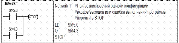
Информация о состоянии модуля хранится в битах специальной памяти (SM). Ваша программа может контролировать и анализировать эти биты. Бит SM5.0 является глобальным битом ошибок конфигурации входов/выходов, который остается установленным, пока в модуле расширения сохраняется сбойная ситуация.
Ошибки выполнения программы
Ваша программа может создавать состояния ошибки во время своего выполнения. Эти ошибки могут возникать из-за ненадлежащего использования команды или из-за обработки командой недопустимых данных. Например, указатель косвенного адреса, который был действительным, когда программа компилировалась, может быть изменен во время выполнения программы так, что станет указывать на адрес вне допустимого диапазона. Это пример ошибки программирования, проявляющейся при выполнении программы. При возникновении такой ошибки устанавливается бит SM4.3. Он остается установленным, пока ПЛК находится в режиме RUN. Информация об ошибках выполнения программы хранится в битах специальной памяти (SM). Ваша программа может контролировать и анализировать эти биты.
Когда ПЛК обнаруживает нефатальную ошибку, он не переключается в режим STOP. Он только регистрирует событие в памяти SM и продолжает выполнение вашей программы. Однако вы можете спроектировать свою программу так, чтобы она принуждала ПЛК к переходу в состояние STOP, когда обнаруживается нефатальная ошибка. Следующий пример показывает сегмент программы, которая контролирует два глобальных бита нефатальных ошибок и переводит ПЛК в STOP всякий раз, когда устанавливается любой из этих битов.
Фатальные ошибки
Фатальные ошибки заставляют ПЛК прекратить выполнение программы. В зависимости от тяжести фатальной ошибки ПЛК может потерять способность к выполнению некоторых или всех функций. Целью обработки фатальных ошибок является перевод ПЛК в безопасное состояние, из которого ПЛК может реагировать на запросы о существующих сбойных состояниях. Когда ПЛК обнаруживает фатальную ошибку, он переключается в режим STOP, включает светодиоды SF/DIAG (красный) и STOP, заменяет таблицу выходов и выключает выходы. ПЛК остается в этом состоянии до исправления фатальной ошибки.
После устранения фатальной ошибки можно перезапустить ПЛК, используя один из следующих методов:
- Выключите, а затем включите питание.
- Переведите переключатель режимов работы из RUN или TERM в STOP.
- Выберите из STEP 7-Micro/WIN команду меню PLC > Power–Up Reset [ПЛК > Сброс при запуске] для запуска ПЛК. Это заставляет ПЛК перезапуститься и сбросить все фатальные ошибки.
Перезапуск ПЛК сбрасывает состояние фатальной ошибки и выполняет диагностический тест, связанный с включением питания, чтобы проверить, что фатальная ошибка была устранена. Если обнаруживается другая фатальная ошибка, то ПЛК снова устанавливает светодиод ошибки, показывая, что ошибка по-прежнему существует. В противном случае ПЛК начинает нормальную работу. Имеется несколько возможных сбойных состояний, которые могут сделать ПЛК некоммуникабельным. В этих случаях вы не можете отобразить код ошибки ПЛК. Эти типы ошибок указывают на аппаратные отказы, требующие ремонта ПЛК; их невозможно устранить посредством изменений в программе или очистки памяти ПЛК.
Источник: http://plc24.ru/oshibki-v-plk-siemens/