Заказать оборудование Allen Bradley
Купить Allen Bradley powerflex ошибки в компании Олниса можно оптом или в розницу. Доставим Allen Bradley powerflex ошибки в любой регион России. Можем предложить точный аналог. Работаем напрямую с производителем, не используя посредников.
При работе промышленной электроники производителя Аллен-Брэдли могут возникать определённые ошибки. Чтобы быстро их устранить, необходима помощь наладчика оборудования или можно самостоятельно ознакомиться с инструкцией. Приборы максимально адаптированы для работы новичков и настроить их не составит большого труда.
Серия Allen Bradley PowerFlex представлена частотными преобразователями. Зная специфику их работы и наименование модельного ряда, можно быстро сориентироваться для устранения ошибок в промышленном секторе:
- серия PowerFlex 1305;
- серия PowerFlex 1332;
- серия PowerFlex 70;
- серия PowerFlex 700S;
- серия PowerFlex 1333;
- серия PowerFlex 1334;
- серия PowerFlex 1336;
- серия PowerFlex 1341;
- серия PowerFlex 1351;
- серия PowerFlex 527;
- серия PowerFlex 4M;
- серия PowerFlex 4;
- серия PowerFlex 40;
- серия PowerFlex 40P;
- серия PowerFlex 1352;
- серия PowerFlex 1361;
- серия PowerFlex 160;
- серия PowerFlex 755T;
- серия PowerFlex 755 TL;
- серия PowerFlex 755TR;
- серия PowerFlex 755TM;
- серия PowerFlex 753;
- серия PowerFlex 755;
- серия PowerFlex 700;
- серия PowerFlex 700L;
- серия PowerFlex 523;
- серия PowerFlex 525;
- серия PowerFlex 400.
.gif "Allen Bradley powerflex ошибки")
Кодировка ошибки и ее значение
Для всех вышеперечисленных частотников наиболее характерны следующие шифры ошибок:
- сбой F2 – ошибка входа в Auxiliary;
- сбой F3 – нарушение или обрыв фазы сети при подключении;
- сбой F4 – слишком низкий показатель электронапряжения в сети;
- сбой F5 – слишком высокий показатель электронапряжения в сети;
- сбой F6 – поломка двигателя, есть механические повреждения, мешающие нормальной работе устройства;
- сбой F7 – перегрузка электромотора напряжением, опасность;
- сбой F8 – начинает перегреваться радиатор;
- сбой F12 – пиковый скачок напряжения с прицельным электроударом на аппарат;
- сбой F13 – произошло короткое замыкание контакта заземления;
- сбой F29 – аналоговый вход неисправен;
- сбой F33 – невозможно переподключиться автоматически, превышен лимит авто запроса;
- сбои в диапазоне F38-43 – сигнализируют о нарушениях работы фаз U, V, W и их коннекта между собой;
- сбой F48 – аварийный сброс всех предустановленных автонастроек;
- сбой F63 – сбой установки ПО;
- сбой F64 – внезапная перезагрузка в процессе работы –неисправность системы;
- сбой F70 – силовая часть аппарата вышла из строя;
- сбой F71 – нарушена обратная связь с контролирующим устройством;
- сбой F80 – автоматические корректировки более работают, требуется перезагрузка системы;
- error F81 – неисправен порт RS-485;
- сбой F100 – отказ подсчета суммы записанных параметров;
- сбой F122 – плата ввода/вывода вышла из строя.
Это основной перечень, который легко устранить, следуя руководству по эксплуатации преобразователей частоты Аллен-Брэдли.
.gif "Allen Bradley powerflex ошибки")
Покупка в «Олниса»
Выбор конкретного устройства и его настройка – задача специалиста или работника, ответственного за контроль прибора. Оригинальные устройства с длительной гарантией работы и полным сервисным обслуживанием на протяжении 12 месяцев от момента покупки вы найдете в нашем онлайн-каталоге.
Все приборы Allen Bradley можно приобрести с доставкой по России или любому другому городу на территории СНГ.
10 февраля 2023 г. 04:04

При работе промышленной электроники Allen Bradley в системах вентиляции, теплоснабжения или автоматизированном производственном оборудовании часто возникают неисправности, распознать которые можно считав коды ошибок и произведя расшифровку этих кодов по инструкции на конкретную модель электронного оборудования. Наиболее частое использование в промышленном оборудовании получили следующие частотные преобразователи фирмы Allen Bradley: PowerFlex, 1305 Series, 1332 Series, 1333 Series, 1334 Series, 1336 Series, 1341 Series, 1351 Series, 1352 Series, 1361 Series, 160 Series,. В свою очередь серия Allen Bradley PowerFlex включает в себя следующие модели: PowerFlex 755T, PowerFlex 755TL, PowerFlex 755TR, PowerFlex 755TM, PowerFlex 753, PowerFlex 755, PowerFlex 755T, PowerFlex 70, PowerFlex 700S, PowerFlex 700, PowerFlex 700L, PowerFlex 523, PowerFlex 525, PowerFlex 527, PowerFlex 4M, PowerFlex 4, PowerFlex 40, PowerFlex 40P, PowerFlex 400. Своевременная расшифровка ошибок может значительно ускорить диагностику и ремонт преобразователей частоты, подробнее об этом написано здесь.
Частотные преобразователи Allen Bradley имеют следующие распространенные ошибки:
Наиболее частые ошибки преобразователей Allen Bradley PowerFlex 40:
Ошибка F2 (error F2) — ошибка входа Auxiliary;
Ошибка F3 (error F3) — обрыв фазы на входе;
Ошибка F4 (error F4) — пониженное напряжение;
Ошибка F5 (error F5) — перенапряжение;
Ошибка F6 (error F6) — механическая неисправность двигателя;
Ошибка F7 (error F7) — перегрузка двигателя;
Ошибка F8 (error F8) — перегрев радиатора;
Ошибка F12 (error F12) — аппаратная перегрузка по току;
Ошибка F13 (error F13) — короткое замыкание на землю;
Ошибка F29 (error F29) — ошибка аналогового входа;
Ошибка F33 (error F33) — превышено количество попыток автоматического повторного включения — АПВ;
Ошибка F38 (error F38) — замыкание фазы U на землю на выходе ПЧ;
Ошибка F39 (error F39) — замыкание фазы V на землю на выходе ПЧ;
Ошибка F40 (error F40) — замыкание фазы W на землю на выходе ПЧ;
Ошибка F41 (error F41) — короткое замыкание между фазами UV;
Ошибка F42 (error F42) — короткое замыкание между фазами UW;
Ошибка F43 (error F43) — короткое замыкание между фазами VW;
Ошибка F48 (error F48) — параметры EEPROM были сброшены;
Ошибка F63 (error F63) — перегрузка по току по программной уставке;
Ошибка F64 (error F64) — перегрузка во время работы;
Ошибка F70 (error F70) — неисправность силовой части;
Ошибка F71 (error F71) — ошибка связи;
Ошибка F80 (error F80) — ошибка автонастройки;
Ошибка F81 (error F81) — ошибка связи RS485;
Ошибка F100 (error F100) — ошибка контрольной суммы записанных параметров;
Ошибка F122 (error F122) — ошибка платы ввода-вывода.
Контактная информация
Время выполнения запроса: 0,00210690498352 секунды.
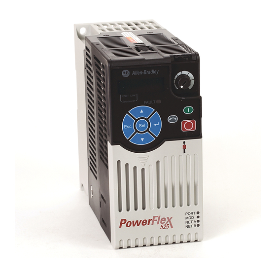
When your Allen Bradley PowerFlex 525 drive gives trouble, diagnosing the issue and getting the drive back in service quickly can be imperative. Fortunately, most problems with the PowerFlex 525 drive series VFD products can be diagnosed by the fault code indicated on its display.
Below are listed the PowerFlex 525 Fault Codes with fault number, Fault/Alarm Text, description of the fault and possible solutions. For more detailed information, see below for a link to the PowerFlex 525 troubleshooting guide.
Fault Name/Description/Action
F000 No Fault
No fault present.
——
F002 Auxiliary Input
External trip (Auxiliary) input.
• Check remote wiring.
• Verify communications programming for intentional fault.
——
F003 Power Loss
Single phase operation detected with excessive load.
• Monitor the incoming AC line for low voltage or line power interruption.
• Check input fuses.
——
F004 UnderVoltage
DC bus voltage fell below the minimum value.
• Monitor the incoming AC line for low voltage or line power interruption.
——
F005 OverVoltage
DC bus voltage exceeded maximum value.
• Monitor the AC line for high line voltage or transient conditions. Bus overvoltage can also be caused by motor regeneration. Extend the decel time or install dynamic brake option.
——
F006 Motor Stalled
Drive is unable to accelerate or decelerate motor.
• Increase P041, A442, A444, A446 [Accel Time x] or reduce load so drive output current does not exceed the current set by parameter A484, A485 [Current Limit x] for too long.
——
F007 Motor Overload
Internal electronic overload trip.
• An excessive motor load exists.
• Reduce load so drive output current does not exceed the current set by parameter P033 [Motor OL Current].
• Verify A530 [Boost Select] setting.
——
F008 Heatsink OvrTmp
Heatsink/Power Module temperature exceeds a predefined value.
• Check for blocked or dirty heat sink fins.
• Verify that ambient temperature has not exceeded the rated ambient temperature.
• Check fan.
——
F009 CC OvrTmp
Control module temperature exceeds a predefined value.
• Check product ambient temperature.
• Check for airflow obstruction.
• Check for dirt or debris.
• Check fan.
——
F012 HW OverCurrent
The drive output current has exceeded the hardware current limit.
• Check programming.
• Check for excess load, improper A530 [Boost Select] setting, DC brake volts set too high or other causes of excess current.
——
F013 Ground Fault
A current path to earth ground has been detected at one or more of the drive output terminals.
• Check the motor and external wiring to the drive output terminals for a grounded condition.
——
F015 Load Loss
The output torque current is below the value programmed in A490 [Load Loss Level] for a time period greater than the time programmed in A491 [Load Loss Time].
• Verify connections between motor and load.
• Verify level and time requirements
——
F021 Output Ph Loss
Output Phase Loss (if enabled).
Configure with A557 [Out Phas Loss En].
• Verify motor wiring.
• Verify motor.
——
F029 Analog In Loss
An analog input is configured to fault on signal loss. A signal loss has occurred. Configure with t094 [Anlg In V Loss] or t097 [Anlg In mA Loss].
• Check for broken/loose connections at inputs.
• Check parameters.
——
F033 Auto Rstrt Tries
Drive unsuccessfully attempted to reset a fault and resume running for the programmed number of A541 [Auto Rstrt Tries].
• Correct the cause of the fault and manually clear.
——
F038 Phase U to Gnd
A phase to ground fault has been detected between the drive and motor in this phase.
• Check the wiring between the drive and motor.
• Check motor for grounded phase.
——
F039 Phase V to Gnd
A phase to ground fault has been detected between the drive and motor in this phase.
• Check the wiring between the drive and motor.
• Check motor for grounded phase.
——
F040 Phase W to Gnd
A phase to ground fault has been detected between the drive and motor in this phase.
• Check the wiring between the drive and motor.
• Check motor for grounded phase.
——
F041 Phase UV Short
Excessive current has been detected between these two output terminals.
• Check the motor and drive output terminal wiring for a shorted condition.
——
F042 Phase UW Short
Excessive current has been detected between these two output terminals.
• Check the motor and drive output terminal wiring for a shorted condition.
——
F043 Phase VW Short
Excessive current has been detected between these two output terminals.
• Check the motor and drive output terminal wiring for a shorted condition.
——
F048 Params Defaulted
The drive was commanded to write default values to EEPROM.
• Clear the fault or cycle power to the drive.
• Program the drive parameters as needed.
——
F059 Safety Open
Both of the safety inputs (Safety 1, Safety 2) are not enabled. Configure with t105 [Safety Open En].
• Check safety input signals. If not using safety, verify and tighten jumper for I/O terminals S1, S2 and S+.
——
F063 SW OverCurrent
Programmed A486, A488 [Shear Pinx Level] has been exceeded for a time period greater than the time programmed in A487, A489 [Shear Pin x Time].
• Verify connections between motor and load.
• Verify level and time requirements.
——
F064 Drive Overload
Drive overload rating has been exceeded.
• Reduce load or extend Accel Time.
——
F070 Power Unit
Failure has been detected in the drive power section.
• Check maximum ambient temperature has not been exceeded.
• Cycle power.
• Replace drive if fault cannot be cleared.
——
F071 DSI Net Loss
Control over the Modbus or DSI communication link has been interrupted.
• Cycle power.
• Check communications cabling.
• Check Modbus or DSI setting.
• Check Modbus or DSI status.
——
F072 Opt Net Loss
Control over the network option card’s remote network has been interrupted.
• Cycle power.
• Check communications cabling.
• Check network adapter setting.
• Check external network status.
——
F073 EN Net Loss
Control through the embedded EtherNet/IP adapter has been interrupted.
• Cycle power.
• Check communications cabling.
• Check EtherNet/IP setting.
• Check external network status.
——
F080 Autotune Failure
The autotune function was either cancelled by the user or failed.
• Restart procedure.
——
F081 DSI Comm Loss
Communications between the drive and the Modbus or DSI master device have been interrupted.
• Cycle power.
• Check communications cabling.
• Check Modbus or DSI setting.
• Check Modbus or DSI status.
• Modify using C125 [Comm Loss Action].
• Connecting I/O terminals C1 and C2 to ground may improve noise immunity.
• Replace wiring, Modbus master device, or control module.
——
F082 Opt Comm Loss
Communications between the drive and the network option card have been interrupted.
• Cycle power.
• Reinstall option card in drive.
• Modify using C125 [Comm Loss Action].
• Replace wiring, port expander, option card, or control module.
——
F083 EN Comm Loss
Internal communications between the drive and the embedded EtherNet/IP adapter have been interrupted.
• Cycle power.
• Check EtherNet/IP setting.
• Check drive’s Ethernet settings and diagnostic parameters.
• Modify using C125 [Comm Loss Action].
• Replace wiring, Ethernet switch, or control module.
——
F091 Encoder Loss
Requires differential encoder. One of the 2 encoder channel signals is missing.
• Check Wiring.
• If P047, P049, P051 [Speed Referencex] = 16 “Positioning” and A535 [Motor Fdbk Type] = 5 “Quad Check”, swap the Encoder channel inputs or swap any two motor leads.
• Replace encoder.
——
F094 Function Loss
“Freeze-Fire” (Function Loss) input is inactive, input to the programmed terminal is open.
• Close input to the terminal and cycle power.
——
F100 Parameter Chksum
Drive parameter non-volatile storage is corrupted.
• Set P053 [Reset To Defalts] to 2 “Factory Rset”.
——
F101 External Storage
External non-volatile storage has failed.
• Set P053 [Reset To Defalts] to 2 “Factory Rset”.
——
F105 C Connect Err
Control module was disconnected while drive was powered.
• Clear fault and verify all parameter settings. Do not remove or install the control module while power is applied.
——
F106 Incompat C-P
The PowerFlex 525 control module does not support power modules with 0.25 HP power rating.
• Change to a different power module.
• Change to a PowerFlex 523 control module.
——
F107 Replaced C-P
The control module could not recognize the power module. Hardware failure.
• Change to a different power module.
• Replace control module if changing power module does not work.
——
F109 Mismatch C-P
The control module was mounted to a different drive type power module.
• Set P053 [Reset To Defalts] to 3 “Power Reset”.
——
F110 Keypad Membrane
Keypad membrane failure / disconnected.
• Cycle power.
• Replace control module if fault cannot be cleared.
——
F111 Safety Hardware
Safety input enable hardware malfunction. One of the safety inputs is not enabled.
• Check safety input signals. If not using safety, verify and tighten jumper for I/O terminals S1, S2 and S+.
• Replace control module if fault cannot be cleared.
——
F114 uC Failure
Microprocessor failure.
• Cycle power.
• Replace control module if fault cannot be cleared.
——
F122 I/O Board Fail
Failure has been detected in the drive control and I/O section.
• Cycle power.
• Replace drive or control module if fault cannot be cleared.
——
F125 Flash Update Req
The firmware in the drive is corrupt, mismatched, or incompatible with the hardware.
• Perform a firmware flash update operation to attempt to load a valid set of firmware.
——
F126 NonRecoverablErr
A non-recoverable firmware or hardware error was detected. The drive was automatically stopped and reset.
• Clear fault or cycle power to the drive.
• Replace drive or control module if fault cannot be cleared.
——
F127 DSIFlashUpdatReq
A critical problem with the firmware was detected and the drive is running using backup firmware that only supports DSI communications.
• Perform a firmware flash update operation using DSI communications to attempt to load a valid set of firmware.
——
If you determine that your PowerFlex 525 drive needs service, or you’re just not sure, give us a call at 1-800-732-4695 to send your defective VFD in for repair. We have the experience necessary to get your defective PowerFlex 525 back in operation quickly with our quality repair service.
*There is a link to the troubleshooting section of the PowerFlex 525 manual below.
-
Contents
-
Table of Contents
-
Bookmarks
Quick Links
PowerFlex 525
Network-Enabled
Commissioning Lab
Related Manuals for Rockwell Automation Allen-Bradley PowerFlex 525
Summary of Contents for Rockwell Automation Allen-Bradley PowerFlex 525
-
Page 1
PowerFlex 525 Network-Enabled Commissioning Lab… -
Page 2: Table Of Contents
Network-Enabled PowerFlex 525 Commissioning Lab Contents Before you begin …………………………..3 About this lab …………………………..3 Tools & Prerequisites …………………………3 Network Setup …………………………..4 About the Demo Box …………………………5 Exercise 1: Using the HIM Keypad and Display ………………….6 Information …………………………….
-
Page 3: Before You Begin
Before you begin Please review the following information before starting this lab. About this lab Learn the basics of drive programming using the new PowerFlex 525 AC drive. Students will configure and commission the 525 drive utilizing a USB cable “Mains Free” with Connected Components Workbench™ and RS Logix 5000 version 20.01. Finally, this lab shows how Premier Integration enhances the use of the Network-Enabled PowerFlex 525 drive with Logix controllers.
-
Page 4: Network Setup
Setup Network Ethernet Connections Connect From Connect To Laptop PC Switch on Demo L43/L35e E-net port Switch on Demo PF525 Drive E-net port Switch on Demo Laptop PC PowerFlex 525 Drive 1769-L35e Demo IP Addresses For Demos Laptop PC 100.100.100.100 1769-L35e/L43 100.100.100.35 PF-525 Drive…
-
Page 5: About The Demo Box
About the Demo Boxes 1769-L35e Demo Switch Start Stop 1769-L43 Demo Stop Start Switch Page 5 of 64…
-
Page 6: Exercise 1: Using The Him Keypad And Display
Exercise 1: Using the HIM Keypad and Display In this section you will perform the following: Review key information about the HIM keypad and display of the PowerFlex 525 • Reset the PowerFlex 525 drive to defaults • Configure several parameters •…
-
Page 7
Display and Control Keys AppView: Dedicated sets of parameters grouped together for the following applications • Conveyor Mixer Compressor Centrifugal Pump Blower Extruder Positioning Textile / Fiber CustomView: Parameter Groups can be customized specifically for your application • Add up to a max of 100 parameters Save new “CustomView”… -
Page 8
Control and Navigation Keys Page 8 of 64… -
Page 9
Viewing and Editing Parameters The following is an example of basic integral keypad and display functions. This example provides basic navigation instructions and illustrates how to program a parameter. Just read through the following. Page 9 of 64… -
Page 10: Reset Drive To Defaults
Reset Drive to Defaults Press the Esc button until you see on the keypad display. Press the Select button and use the Up or Down arrows until you see the Basic Program group on the HIM display. Press the Enter or Sel button to enter the Basic Program group.
-
Page 11: Configuring Drive Parameters
Once is displayed, Press the Enter button. You will see “0 — Ready/Idle” scroll across the “2 – Factory Reset”. display. Press the Up or Down arrows until you see Press the Enter button to confirm. The drive will fault with a scrolling message of “F048 – Parameters Defaulted” See picture below.
-
Page 12: Exercise 2: Using The Usb To Access «Mains Free» Drive Configuration Files In The Control Module
Exercise 2: Using the USB to access “Mains Free” Drive configuration files in the Control Module The purpose of this exercise is to access the drive configuration file (xxxxx.PF5) in the drive so it can be imported into the Connected Components Work Bench or RS Logix 5000 software program where you can make parameter changes. This file can then be exported out to a xxxxx.PF5 file which can then be down loaded back into the drive with the utility using the USB cable.
-
Page 13
Select or click on the “Upload” Button: Click on Next: Click on Browse: then select LibrariesDocumentsMyDocumentsNetwork Expo Labs 8. Give the File your desired name and store it where ever you like. For this Lab please type in the following name: PF525_Drive.pf5. -
Page 14
10. Click on the Upload button. 11. Click on the Close Button and close any other boxes or screens that may be open. Later we will use this utility to download the completed drive configuration file back into the drive. This utility is just used to upload and download the drive file and it cannot make any changes to the Parameters. -
Page 15: Exercise 3: Utilizing The File In Drive And Connected Component Workbench Offline With Usb Cable
Go to the computer’s desktop and double click the Connected Components Workbench shortcut. If the shortcut is not on the desk top use the “All Programs” in the Start menu then select the Rockwell Automation folder, then the CCW folder and click on the CCW icon.
-
Page 16
The main screen for Connected Components Workbench is as follows. Note: You may want to maximize the Connected Components Workbench software to make viewing easier. Expand the Catalog box and select the “Drives” folder as shown above. Then select ”PF525 Drive” by double mouse clicking it. -
Page 17
Your view will look like this: Click on the “Properties” button Then select the “USB Import Export Tab”. Page 17 of 64… -
Page 18
Click on the “Import” button Select the PF525_Drive.PF5 file from the Network Expo Labs folder: Click on “Import Entire Device” 10. Close the Properties Box Page 18 of 64… -
Page 19
11. Click on the “Parameters” Button. 12. Click on the “All Parameters” button and Select “Baic Program”. 13. The Basic parameters are where the majority of the drive settings will be made. Page 19 of 64… -
Page 20
14. Populate your page with the drive settings as listed below: Note: if you want to view and or configure more drive parameters you can select the various programming groups. 15. Close the Parameters page 16. Click on the “Properties” button. You will now export the drive setting back to the PF525_Drive.PF5 file located in the Network Expo Folder. -
Page 21
17. Then select the “USB Import/ Export Tab”. 18. Click on the “Export” button 19. Select the PF525_Drive.PF5 file from the Network Expo Labs folder then click on the “Save” button: 20. Confirm save by clicking on the “Yes” button do not close 21. -
Page 22
22. Open the Explorer Folder window and click on the “Removable Drive”. Then double mouse click on the PF52xUSB.exe file. 23. Take what you have learned earlier from the uploading procedure and by selecting “Download” move the PF525_Drive.PF5 back to the drive. Note: Refer back to Execise 2. -
Page 23: Exercise 4: Powerflex 525 Start-Up Wizard
Exercise 4: Utilizing an E-net connection and online with the drive. Connected Component Workbench Connect to the PowerFlex 525 through the embedded Ethernet/IP via Connected Components Workbench Explore the Startup wizard. There are many features to Connected Components Workbench. You can set up a driver in RS Linx so that a 1203_USB cable can be used to connect to a PowerFlex drive or the LInx driver can be Ethernet I/P……
-
Page 24
Select the Connect button and using the RS LInx Ethernet/IP driver that appears and find the PF525 Drive, Select it and acknowledge the connection. ( See step 5) The lab’s preconfigured RSLinx driver will appear. Click on the [+] to expand AB_ETHIP-1, Ethernet, click/highlight the 100.100.100.25, PowerFlex 525 1P 110V .50HP device. -
Page 25
The lab’s preconfigured RSLinx driver will appear. Click on the [+] to expand AB_ETHIP-1, Ethernet, click/highlight the 100.100.100.25, PowerFlex 525 1P 110V .50HP device. 10. Press the OK button to initiate the connection process. For a quick moment, you might see a connection status window. Otherwise, once the connection process is complete, you will see the following main screen with a green highlighted “Connected”… -
Page 26: Exploring Drive Parameters Via Parameter Groupings, Appview™, And Customview
Exploring Drive Parameters via Parameter Groupings, AppView™, and CustomView™ There are many features supported by Connected Components Workbench™ for the PowerFlex 525 as shown below. Take some time to explore them. Click on the Parameters icon to view the PowerFlex 525 drive parameters as seen below. The PowerFlex 525 Drive Add-On Profile has a nice new feature from Connected Components Workbench™…
-
Page 27
An upload progress window will pop up. Once the upload has completed you will see the parameters window update to just show only the non-default parameters. Take a look, you will notice that the parameters you changed in Lab 1 appear in this list. Example shown below. Click the Show All button to return to viewing all of the PowerFlex 525 drive parameters. -
Page 28
Try some other examples such as Dig , Speed, 10 and see the results. Note: Remember to clear/delete the entry field when finished. Under the Group: dropdown selection box, you can scroll through the different drive parameter groups, AppView™ and the CustomView™. -
Page 29
These are the most simplistic parameters that are needed to start up/commission a PowerFlex 525 drive. Take some time to explore some of the other parameter groupings such as Terminals, Communications and Advanced Program for more startup/commission parameters. 11. The PowerFlex 525 drive has several AppView™ groupings that are tailored for a specific application to make the respective drive startup/commission simpler. -
Page 30
Note: You can also select/highlight multiple parameters then click the Add — > button. This makes adding parameters go a lot faster. 14. Add the following parameters: Parameter 30 — Language Parameter 43 — Minimum Freq Parameter 31 — Motor NP Volts Parameter 44 — Maximum Freq Parameter 32 — Motor NP Hertz Parameter 45 — Stop Mode… -
Page 31
15. Notice how the parameters entries from above are all now in the ABC’s Group CustomView for easy parameter viewing and editing. Click [X] in the upper right hand corner to Close the Parameters – PowerFlex 525_1* window. Page 31 of 64… -
Page 32
Exercise 4: PowerFlex 525 Start-Up Wizard Click on the Wizards button and Select the PowerFlex 525 Startup Wizard and Click the Select button to launch the PowerFlex 525 Startup wizard. Below is the Welcome screen for the PowerFlex 525 Startup Wizard. Click the Next > button to proceed with exploring the startup wizard. -
Page 33
Below is the Reset Parameters page. Here you have a couple different options. Reset all settings to factory defaults but retain the custom parameter group. • Reset all settings to factory defaults (including the custom parameter group). • Reset only the “Power Parameters”. •… -
Page 34
Go through, verify and if needed, modify the parameters according to the following screenshots. Remember to Click the Next > button to proceed to the next page. If Connected to the drive, and the PLC is not in controll you may execute the Direction Test and if not, you can skip this by Clicking the Next >… -
Page 35
Press Stop button to Clear Faults if the drive is faulted. PRESS and HOLD the Jog button to run the Direction Test. If the following window pops-up, Click “Yes”. If the direction is correct, Click on the Yes radio button and Click the Next > button. -
Page 36
If desired, you may skip the AutoTune Test by Clicking the Next > button. Click on the StaticTune button to initiate the AutoTune Test. (see next page) Note: This may take up to a minute to complete. Once finished, you will see the Test Completed: Yes result. Note: This may take up to a minute to complete. -
Page 37
Page 37 of 64… -
Page 38
This can be any IP Adress of course… Select how you want the Terminal Block inputs to behave. Notice how The GUI shows you which terminals are configurable. Page 38 of 64… -
Page 39
10. Once changes have been made, Go to the Pending Changes page for a summary of the planned programming changes you have made to the PowerFlex 525 drive. Page 39 of 64… -
Page 40
Make sure all the Pages have the black check to the left of the page name / icon. Click the Finish >> button to accept pending changes. 11. The main PowerFlex 525 window will be present. Click the Reset button for the Ethernet communication settings to take affect. -
Page 41
When prompted, Click No. When prompted, Click No. Page 41 of 64… -
Page 42: Exercise 5: Powerflex 525 Drive Add-On Profile With Rs Logix 5000 Software
Exercise 5: PowerFlex 525 Drive Add-On Profile with RS Logix 5000 Software. This section will provide a preview of the PowerFlex 525 Drive Add-On Profile as well as the PowerFlex 525 Drives and Motion Accelerator Toolkit Add-On Instructions and Faceplates for the PowerFlex 525. About Integrated Drive Profiles and Premier Integration Integrated Drive Profiles were designed to save system development time and to make systems easier to maintain.
-
Page 43: Using Rs Logix 5000 With The Powerflex 525 Drive Add-On Profile
Using RS Logix 5000 Version 20.01 with the PowerFlex 525 Drive Add-On Profile Start the program. Double-click the Studio 5000 icon on the desktop, or from the Start menu, select All Programs > Rockwell Software > RSLogix 5000 Enterprise Series> RSLogix 5000. After the splash Screen you will see something like this: A pre-configured RS Logix 5000 program has already been created for your convenience.
-
Page 44
*NOTE* Lab files are located within Libraries>Network Expo>L35ePF525_Lab or Libraries>Network Expo>L35ePF525_Lab folders depending on which demo you are using. Note: May take a minute or two for the RS Logix 5000™ software to open. Open the PowerFlex 525-EENET module properties by double-click on the PowerFlex 525-EENET node in the I/O Configuration folder to display the Module Properties screen. -
Page 45
Click on the Properties button. This opens the properties window and the Setup tab, which shows some basic drive information, such as configuration, revision, device language and electronic keying. = Creates device database from online drive to add new revisions and configurations = Reset device data to factory defaults = Print Page 45 of 64… -
Page 46
Click on the Communications tab to view the settings; you can manually configure the PowerFlex 525 drive Ethernet network settings or obtain via BOOTP or DHCP. The details page. There is also Import / Export for the PF525 USB connection file format, .pf5. It can be used for saving/restoring configurations. -
Page 47
10. The Parameters icon launches the Parameters window. This is the same as what you performed in the previous section with using the Connected Components Workbench™ software to go online with the drive, view and modify parameters with the Parameter, AppView™ and CustomView™ groups 11. -
Page 48
Select the drive rating Set the firmware revision Set the Electronic Keying Configure the Input and Output Datalinks Create Database from the online drive or download from the web. The PowerFlex 525 Add-On Profile provides the ability to configure Up to 4 words of Input Data and 4 words of Output Data can be defined for the embedded Ethernet connection. -
Page 49
Click on the [X] in the upper right hand corner to Close the Module Definition window and then the Module Properties window. 15. If your application required multiple duplicate drives, you could right-click on the PowerFlex 525-EENET to copy it and then right-click on the Ethernet network and paste it as many times as needed. -
Page 50
Where do you think the drive configuration data gets stored? The drive configuration data for each node is actually stored in your Studio 5000 project (the .ACD file)! It also resides in the ControlLogix when the .ACD is downloaded to the controller. This provides a convenient local resource for a node’s configuration settings should the node need replacing. -
Page 51
18. View the output tags. Now expand the PF525_Drive:O output to view the output tag names. Descriptive tag names have been created for the configured I/O. The Logic Command bits (BOOLs) are clearly defined as well as the Reference. Note that the proper data types are used for every tag. Close the Controller Tags window by clicking the lower [X] button in the upper-right corner of the screen. -
Page 52
20. Open the PowerFlex 525-EENET module properties by Double-click on the PowerFlex 525-EENET node in the I/O Configuration folder to display the Module Properties screen. Your view will have the correct Processor indicated. Click on the Drive tab. 21. View the PowerFlex 525-EENET Drive tab. 22. -
Page 53
24. For a brief moment, you will see a downloading progress bar while the parameter settings are being sent to the drive. Your IP address will be 100.100.100.25 25. Click back to the Connections Tab and Select the Inhibit Box by giving it a Check mark. Note: By inhibiting the drive The PLC is prevented from having full ownership of the drive which will let us finish the commissioning process. -
Page 54
29. Put the controller in Run mode. If prompted to confirm Remote Run, click “Yes” Click on the mode drop-down arrow and select Run Mode. Open the PowerFlex 525-EENET module properties by Double-click on the PowerFlex 525-EENET node in the I/O Configuration folder to display the Module Properties screen. -
Page 55
Click on the Drive tab. 32. View the PowerFlex 525-EENET Drive tab. With the PLC on line you are now allowed to go on line with the drive and while the connection is being made you should see something like this. 33. -
Page 56
Start the PowerFlex 525 Start-Up Wizard Again so we can use it to Bump the motor and Auto Tune. 34. Click on the Wizards button and Select the PowerFlex 525 Startup Wizard and Click the Select button to launch the PowerFlex 525 Startup wizard. 35. -
Page 57
Note: The direction of the rotor can be predicted in advance so long as the installer is aware of the lead terminations. The motor as you face the shaft will rotate clockwise (CW) when T1, T2, T3 on the drive is connected with Motor leads T1, T2, and T3. -
Page 58
42. Click on the connection Tab and remove the inhibit or uncheck the box. Click on the Apply button. 43. Then Click on the OK Button. Verify you are still on line with the processor and that you are in Run. 44. -
Page 59
46. Have some fun while monitoring the drive status. 47. You have now completed the PF525 Commisioning lab. Exta Credit:: If you have time and want to learn about ADC or Automatic Device Configuration. See next Section Page 59 of 64… -
Page 60: Exercise 6: Automatic Device Configuration (Adc) With The Powerflex 525 Ac Drive
Exercise 6: Automatic Device Configuration (ADC) with the PowerFlex 525 AC drive About Automatic Device Configuration (ADC) Automatic Device Configuration (ADC) is an RSLogix 5000 (version 20) and Logix Designer (version 21 or greater) feature that supports the automatic download of configuration data upon the Logix controller establishing an EtherNet/IP network connection to a PowerFlex 525 drive and its associated peripherals.
-
Page 61: Exploring The Setup Of Automatic Device Configuration (Adc)
Exploring the setup of Automatic Device Configuration (ADC) Open the PowerFlex 525-EENET module properties by Double-click on the PowerFlex 525-EENET node in the I/O Configuration folder to display the Module Properties screen. Click on the Drive tab. The drive AOP requires user action to enable ADC. This helps ensure that the user understands ADC operation prior to turning it on.
-
Page 62
Click the OK button to Close the PowerFlex 525 Module Properties. Download the PF525_Lab project to the controller by clicking on Communications then Who Active. Make sure the path to the CompactLogix controller at 100.100.100.35 via the AB_ETHIP-1 ethernet driver is selected and click Download. -
Page 63
11. Automatic Device Configuration (ADC) will cause the transition to run to be longer. Click the OK button to confirm / acknowledge the following window. NOTE: ADC will cause the tranistion to run to be longer 12. Notice that the PowerFlex 525 drive will get a F048 – Parameters Defaulted fault on the LCD Keypad display. This is normal and the first step of the Automatic Device Configuration process. -
Page 64
Page 64 of 64…
-
Contents
-
Table of Contents
-
Bookmarks
Quick Links
PowerFlex 525
Network-Enabled
Commissioning Lab
Related Manuals for Rockwell Automation Allen-Bradley PowerFlex 525
Summary of Contents for Rockwell Automation Allen-Bradley PowerFlex 525
-
Page 1
PowerFlex 525 Network-Enabled Commissioning Lab… -
Page 2: Table Of Contents
Network-Enabled PowerFlex 525 Commissioning Lab Contents Before you begin …………………………..3 About this lab …………………………..3 Tools & Prerequisites …………………………3 Network Setup …………………………..4 About the Demo Box …………………………5 Exercise 1: Using the HIM Keypad and Display ………………….6 Information …………………………….
-
Page 3: Before You Begin
Before you begin Please review the following information before starting this lab. About this lab Learn the basics of drive programming using the new PowerFlex 525 AC drive. Students will configure and commission the 525 drive utilizing a USB cable “Mains Free” with Connected Components Workbench™ and RS Logix 5000 version 20.01. Finally, this lab shows how Premier Integration enhances the use of the Network-Enabled PowerFlex 525 drive with Logix controllers.
-
Page 4: Network Setup
Setup Network Ethernet Connections Connect From Connect To Laptop PC Switch on Demo L43/L35e E-net port Switch on Demo PF525 Drive E-net port Switch on Demo Laptop PC PowerFlex 525 Drive 1769-L35e Demo IP Addresses For Demos Laptop PC 100.100.100.100 1769-L35e/L43 100.100.100.35 PF-525 Drive…
-
Page 5: About The Demo Box
About the Demo Boxes 1769-L35e Demo Switch Start Stop 1769-L43 Demo Stop Start Switch Page 5 of 64…
-
Page 6: Exercise 1: Using The Him Keypad And Display
Exercise 1: Using the HIM Keypad and Display In this section you will perform the following: Review key information about the HIM keypad and display of the PowerFlex 525 • Reset the PowerFlex 525 drive to defaults • Configure several parameters •…
-
Page 7
Display and Control Keys AppView: Dedicated sets of parameters grouped together for the following applications • Conveyor Mixer Compressor Centrifugal Pump Blower Extruder Positioning Textile / Fiber CustomView: Parameter Groups can be customized specifically for your application • Add up to a max of 100 parameters Save new “CustomView”… -
Page 8
Control and Navigation Keys Page 8 of 64… -
Page 9
Viewing and Editing Parameters The following is an example of basic integral keypad and display functions. This example provides basic navigation instructions and illustrates how to program a parameter. Just read through the following. Page 9 of 64… -
Page 10: Reset Drive To Defaults
Reset Drive to Defaults Press the Esc button until you see on the keypad display. Press the Select button and use the Up or Down arrows until you see the Basic Program group on the HIM display. Press the Enter or Sel button to enter the Basic Program group.
-
Page 11: Configuring Drive Parameters
Once is displayed, Press the Enter button. You will see “0 — Ready/Idle” scroll across the “2 – Factory Reset”. display. Press the Up or Down arrows until you see Press the Enter button to confirm. The drive will fault with a scrolling message of “F048 – Parameters Defaulted” See picture below.
-
Page 12: Exercise 2: Using The Usb To Access «Mains Free» Drive Configuration Files In The Control Module
Exercise 2: Using the USB to access “Mains Free” Drive configuration files in the Control Module The purpose of this exercise is to access the drive configuration file (xxxxx.PF5) in the drive so it can be imported into the Connected Components Work Bench or RS Logix 5000 software program where you can make parameter changes. This file can then be exported out to a xxxxx.PF5 file which can then be down loaded back into the drive with the utility using the USB cable.
-
Page 13
Select or click on the “Upload” Button: Click on Next: Click on Browse: then select LibrariesDocumentsMyDocumentsNetwork Expo Labs 8. Give the File your desired name and store it where ever you like. For this Lab please type in the following name: PF525_Drive.pf5. -
Page 14
10. Click on the Upload button. 11. Click on the Close Button and close any other boxes or screens that may be open. Later we will use this utility to download the completed drive configuration file back into the drive. This utility is just used to upload and download the drive file and it cannot make any changes to the Parameters. -
Page 15: Exercise 3: Utilizing The File In Drive And Connected Component Workbench Offline With Usb Cable
Go to the computer’s desktop and double click the Connected Components Workbench shortcut. If the shortcut is not on the desk top use the “All Programs” in the Start menu then select the Rockwell Automation folder, then the CCW folder and click on the CCW icon.
-
Page 16
The main screen for Connected Components Workbench is as follows. Note: You may want to maximize the Connected Components Workbench software to make viewing easier. Expand the Catalog box and select the “Drives” folder as shown above. Then select ”PF525 Drive” by double mouse clicking it. -
Page 17
Your view will look like this: Click on the “Properties” button Then select the “USB Import Export Tab”. Page 17 of 64… -
Page 18
Click on the “Import” button Select the PF525_Drive.PF5 file from the Network Expo Labs folder: Click on “Import Entire Device” 10. Close the Properties Box Page 18 of 64… -
Page 19
11. Click on the “Parameters” Button. 12. Click on the “All Parameters” button and Select “Baic Program”. 13. The Basic parameters are where the majority of the drive settings will be made. Page 19 of 64… -
Page 20
14. Populate your page with the drive settings as listed below: Note: if you want to view and or configure more drive parameters you can select the various programming groups. 15. Close the Parameters page 16. Click on the “Properties” button. You will now export the drive setting back to the PF525_Drive.PF5 file located in the Network Expo Folder. -
Page 21
17. Then select the “USB Import/ Export Tab”. 18. Click on the “Export” button 19. Select the PF525_Drive.PF5 file from the Network Expo Labs folder then click on the “Save” button: 20. Confirm save by clicking on the “Yes” button do not close 21. -
Page 22
22. Open the Explorer Folder window and click on the “Removable Drive”. Then double mouse click on the PF52xUSB.exe file. 23. Take what you have learned earlier from the uploading procedure and by selecting “Download” move the PF525_Drive.PF5 back to the drive. Note: Refer back to Execise 2. -
Page 23: Exercise 4: Powerflex 525 Start-Up Wizard
Exercise 4: Utilizing an E-net connection and online with the drive. Connected Component Workbench Connect to the PowerFlex 525 through the embedded Ethernet/IP via Connected Components Workbench Explore the Startup wizard. There are many features to Connected Components Workbench. You can set up a driver in RS Linx so that a 1203_USB cable can be used to connect to a PowerFlex drive or the LInx driver can be Ethernet I/P……
-
Page 24
Select the Connect button and using the RS LInx Ethernet/IP driver that appears and find the PF525 Drive, Select it and acknowledge the connection. ( See step 5) The lab’s preconfigured RSLinx driver will appear. Click on the [+] to expand AB_ETHIP-1, Ethernet, click/highlight the 100.100.100.25, PowerFlex 525 1P 110V .50HP device. -
Page 25
The lab’s preconfigured RSLinx driver will appear. Click on the [+] to expand AB_ETHIP-1, Ethernet, click/highlight the 100.100.100.25, PowerFlex 525 1P 110V .50HP device. 10. Press the OK button to initiate the connection process. For a quick moment, you might see a connection status window. Otherwise, once the connection process is complete, you will see the following main screen with a green highlighted “Connected”… -
Page 26: Exploring Drive Parameters Via Parameter Groupings, Appview™, And Customview
Exploring Drive Parameters via Parameter Groupings, AppView™, and CustomView™ There are many features supported by Connected Components Workbench™ for the PowerFlex 525 as shown below. Take some time to explore them. Click on the Parameters icon to view the PowerFlex 525 drive parameters as seen below. The PowerFlex 525 Drive Add-On Profile has a nice new feature from Connected Components Workbench™…
-
Page 27
An upload progress window will pop up. Once the upload has completed you will see the parameters window update to just show only the non-default parameters. Take a look, you will notice that the parameters you changed in Lab 1 appear in this list. Example shown below. Click the Show All button to return to viewing all of the PowerFlex 525 drive parameters. -
Page 28
Try some other examples such as Dig , Speed, 10 and see the results. Note: Remember to clear/delete the entry field when finished. Under the Group: dropdown selection box, you can scroll through the different drive parameter groups, AppView™ and the CustomView™. -
Page 29
These are the most simplistic parameters that are needed to start up/commission a PowerFlex 525 drive. Take some time to explore some of the other parameter groupings such as Terminals, Communications and Advanced Program for more startup/commission parameters. 11. The PowerFlex 525 drive has several AppView™ groupings that are tailored for a specific application to make the respective drive startup/commission simpler. -
Page 30
Note: You can also select/highlight multiple parameters then click the Add — > button. This makes adding parameters go a lot faster. 14. Add the following parameters: Parameter 30 — Language Parameter 43 — Minimum Freq Parameter 31 — Motor NP Volts Parameter 44 — Maximum Freq Parameter 32 — Motor NP Hertz Parameter 45 — Stop Mode… -
Page 31
15. Notice how the parameters entries from above are all now in the ABC’s Group CustomView for easy parameter viewing and editing. Click [X] in the upper right hand corner to Close the Parameters – PowerFlex 525_1* window. Page 31 of 64… -
Page 32
Exercise 4: PowerFlex 525 Start-Up Wizard Click on the Wizards button and Select the PowerFlex 525 Startup Wizard and Click the Select button to launch the PowerFlex 525 Startup wizard. Below is the Welcome screen for the PowerFlex 525 Startup Wizard. Click the Next > button to proceed with exploring the startup wizard. -
Page 33
Below is the Reset Parameters page. Here you have a couple different options. Reset all settings to factory defaults but retain the custom parameter group. • Reset all settings to factory defaults (including the custom parameter group). • Reset only the “Power Parameters”. •… -
Page 34
Go through, verify and if needed, modify the parameters according to the following screenshots. Remember to Click the Next > button to proceed to the next page. If Connected to the drive, and the PLC is not in controll you may execute the Direction Test and if not, you can skip this by Clicking the Next >… -
Page 35
Press Stop button to Clear Faults if the drive is faulted. PRESS and HOLD the Jog button to run the Direction Test. If the following window pops-up, Click “Yes”. If the direction is correct, Click on the Yes radio button and Click the Next > button. -
Page 36
If desired, you may skip the AutoTune Test by Clicking the Next > button. Click on the StaticTune button to initiate the AutoTune Test. (see next page) Note: This may take up to a minute to complete. Once finished, you will see the Test Completed: Yes result. Note: This may take up to a minute to complete. -
Page 37
Page 37 of 64… -
Page 38
This can be any IP Adress of course… Select how you want the Terminal Block inputs to behave. Notice how The GUI shows you which terminals are configurable. Page 38 of 64… -
Page 39
10. Once changes have been made, Go to the Pending Changes page for a summary of the planned programming changes you have made to the PowerFlex 525 drive. Page 39 of 64… -
Page 40
Make sure all the Pages have the black check to the left of the page name / icon. Click the Finish >> button to accept pending changes. 11. The main PowerFlex 525 window will be present. Click the Reset button for the Ethernet communication settings to take affect. -
Page 41
When prompted, Click No. When prompted, Click No. Page 41 of 64… -
Page 42: Exercise 5: Powerflex 525 Drive Add-On Profile With Rs Logix 5000 Software
Exercise 5: PowerFlex 525 Drive Add-On Profile with RS Logix 5000 Software. This section will provide a preview of the PowerFlex 525 Drive Add-On Profile as well as the PowerFlex 525 Drives and Motion Accelerator Toolkit Add-On Instructions and Faceplates for the PowerFlex 525. About Integrated Drive Profiles and Premier Integration Integrated Drive Profiles were designed to save system development time and to make systems easier to maintain.
-
Page 43: Using Rs Logix 5000 With The Powerflex 525 Drive Add-On Profile
Using RS Logix 5000 Version 20.01 with the PowerFlex 525 Drive Add-On Profile Start the program. Double-click the Studio 5000 icon on the desktop, or from the Start menu, select All Programs > Rockwell Software > RSLogix 5000 Enterprise Series> RSLogix 5000. After the splash Screen you will see something like this: A pre-configured RS Logix 5000 program has already been created for your convenience.
-
Page 44
*NOTE* Lab files are located within Libraries>Network Expo>L35ePF525_Lab or Libraries>Network Expo>L35ePF525_Lab folders depending on which demo you are using. Note: May take a minute or two for the RS Logix 5000™ software to open. Open the PowerFlex 525-EENET module properties by double-click on the PowerFlex 525-EENET node in the I/O Configuration folder to display the Module Properties screen. -
Page 45
Click on the Properties button. This opens the properties window and the Setup tab, which shows some basic drive information, such as configuration, revision, device language and electronic keying. = Creates device database from online drive to add new revisions and configurations = Reset device data to factory defaults = Print Page 45 of 64… -
Page 46
Click on the Communications tab to view the settings; you can manually configure the PowerFlex 525 drive Ethernet network settings or obtain via BOOTP or DHCP. The details page. There is also Import / Export for the PF525 USB connection file format, .pf5. It can be used for saving/restoring configurations. -
Page 47
10. The Parameters icon launches the Parameters window. This is the same as what you performed in the previous section with using the Connected Components Workbench™ software to go online with the drive, view and modify parameters with the Parameter, AppView™ and CustomView™ groups 11. -
Page 48
Select the drive rating Set the firmware revision Set the Electronic Keying Configure the Input and Output Datalinks Create Database from the online drive or download from the web. The PowerFlex 525 Add-On Profile provides the ability to configure Up to 4 words of Input Data and 4 words of Output Data can be defined for the embedded Ethernet connection. -
Page 49
Click on the [X] in the upper right hand corner to Close the Module Definition window and then the Module Properties window. 15. If your application required multiple duplicate drives, you could right-click on the PowerFlex 525-EENET to copy it and then right-click on the Ethernet network and paste it as many times as needed. -
Page 50
Where do you think the drive configuration data gets stored? The drive configuration data for each node is actually stored in your Studio 5000 project (the .ACD file)! It also resides in the ControlLogix when the .ACD is downloaded to the controller. This provides a convenient local resource for a node’s configuration settings should the node need replacing. -
Page 51
18. View the output tags. Now expand the PF525_Drive:O output to view the output tag names. Descriptive tag names have been created for the configured I/O. The Logic Command bits (BOOLs) are clearly defined as well as the Reference. Note that the proper data types are used for every tag. Close the Controller Tags window by clicking the lower [X] button in the upper-right corner of the screen. -
Page 52
20. Open the PowerFlex 525-EENET module properties by Double-click on the PowerFlex 525-EENET node in the I/O Configuration folder to display the Module Properties screen. Your view will have the correct Processor indicated. Click on the Drive tab. 21. View the PowerFlex 525-EENET Drive tab. 22. -
Page 53
24. For a brief moment, you will see a downloading progress bar while the parameter settings are being sent to the drive. Your IP address will be 100.100.100.25 25. Click back to the Connections Tab and Select the Inhibit Box by giving it a Check mark. Note: By inhibiting the drive The PLC is prevented from having full ownership of the drive which will let us finish the commissioning process. -
Page 54
29. Put the controller in Run mode. If prompted to confirm Remote Run, click “Yes” Click on the mode drop-down arrow and select Run Mode. Open the PowerFlex 525-EENET module properties by Double-click on the PowerFlex 525-EENET node in the I/O Configuration folder to display the Module Properties screen. -
Page 55
Click on the Drive tab. 32. View the PowerFlex 525-EENET Drive tab. With the PLC on line you are now allowed to go on line with the drive and while the connection is being made you should see something like this. 33. -
Page 56
Start the PowerFlex 525 Start-Up Wizard Again so we can use it to Bump the motor and Auto Tune. 34. Click on the Wizards button and Select the PowerFlex 525 Startup Wizard and Click the Select button to launch the PowerFlex 525 Startup wizard. 35. -
Page 57
Note: The direction of the rotor can be predicted in advance so long as the installer is aware of the lead terminations. The motor as you face the shaft will rotate clockwise (CW) when T1, T2, T3 on the drive is connected with Motor leads T1, T2, and T3. -
Page 58
42. Click on the connection Tab and remove the inhibit or uncheck the box. Click on the Apply button. 43. Then Click on the OK Button. Verify you are still on line with the processor and that you are in Run. 44. -
Page 59
46. Have some fun while monitoring the drive status. 47. You have now completed the PF525 Commisioning lab. Exta Credit:: If you have time and want to learn about ADC or Automatic Device Configuration. See next Section Page 59 of 64… -
Page 60: Exercise 6: Automatic Device Configuration (Adc) With The Powerflex 525 Ac Drive
Exercise 6: Automatic Device Configuration (ADC) with the PowerFlex 525 AC drive About Automatic Device Configuration (ADC) Automatic Device Configuration (ADC) is an RSLogix 5000 (version 20) and Logix Designer (version 21 or greater) feature that supports the automatic download of configuration data upon the Logix controller establishing an EtherNet/IP network connection to a PowerFlex 525 drive and its associated peripherals.
-
Page 61: Exploring The Setup Of Automatic Device Configuration (Adc)
Exploring the setup of Automatic Device Configuration (ADC) Open the PowerFlex 525-EENET module properties by Double-click on the PowerFlex 525-EENET node in the I/O Configuration folder to display the Module Properties screen. Click on the Drive tab. The drive AOP requires user action to enable ADC. This helps ensure that the user understands ADC operation prior to turning it on.
-
Page 62
Click the OK button to Close the PowerFlex 525 Module Properties. Download the PF525_Lab project to the controller by clicking on Communications then Who Active. Make sure the path to the CompactLogix controller at 100.100.100.35 via the AB_ETHIP-1 ethernet driver is selected and click Download. -
Page 63
11. Automatic Device Configuration (ADC) will cause the transition to run to be longer. Click the OK button to confirm / acknowledge the following window. NOTE: ADC will cause the tranistion to run to be longer 12. Notice that the PowerFlex 525 drive will get a F048 – Parameters Defaulted fault on the LCD Keypad display. This is normal and the first step of the Automatic Device Configuration process. -
Page 64
Page 64 of 64…