-
Contents
-
Table of Contents
-
Troubleshooting
-
Bookmarks
Quick Links
INSTRUCTION MANUAL
ARC FUSION SPLICER
F S M – 6 0 S
Please read this instruction manual carefully
before operating the equipment.
Adhere to all safety instructions and
warnings contained in this manual.
Keep this manual in a safe place.
Related Manuals for Fujikura FSM–60S
Summary of Contents for Fujikura FSM–60S
-
Page 1
INSTRUCTION MANUAL ARC FUSION SPLICER F S M – 6 0 S Please read this instruction manual carefully before operating the equipment. Adhere to all safety instructions and warnings contained in this manual. Keep this manual in a safe place. -
Page 3: Table Of Contents
Table of Contents Warning and Caution………….. 3 Introduction …………….9 Description of Product …………12 1. Components of Splicer ………………… 12 2. Other Necessary Items for Splicing Operation…………14 3. Description and Function of Splicer …………… 16 Point of the splice procedure……….20 1.
-
Page 4
Maintenance Menu …………… 92 1. Replace Electrodes………………..93 2. Stabilize Electrodes………………..94 3. Clear Arc Count………………….94 4. Battery Discharge ………………… 95 5. Set Calendar………………….96 6. Maintenance Info…………………. 96 7. Diagnostic Test Function………………97 8. Dust Check …………………… 98 9. -
Page 5: Warning And Caution
The splicer has been designed for splicing Silica-based optical fibers for telecommunications. Do not attempt to use this machine for other applications. Fujikura Ltd. gives much consideration and regard to personal injury. Misuse of the machine may result in electric shock, fire and/or serious personal injury.
-
Page 6
Warning and Caution WARNINGS Do not take the protector off the splicer, or consult your distributor for instruction. Tightening the original screw without the protector may damage mechanism inside. An environmental performance decreases when the protector is detached. -
Page 7
Warning and Caution WARNINGS Disconnect the AC power cord from the AC adapter inlet or the wall socket (outlet) immediately if user observes the following or if the splicer receives the following faults: • Fumes, bad smell, noise, or over-heat occurs. •… -
Page 8
When using an AC generator with AC output voltage of AC220-240V especially, Fujikura Ltd. recommends the following measures to correct the condition. (1) Connect a step-down transformer between the generator and the AC adapter in order to lower the AC voltage from AC220-240V to AC100-120V. -
Page 9
Warning and Caution WARNINGS Do not touch the splicer, AC power cord and AC plugs with wet hands. This may result in electric shock. Do not operate splicer near hot objects, in hot temperature environments, in dusty / humid atmospheres or when water-condensation is present on the splicer. This may result in electric shock, splicer malfunction or poor splicing performance. -
Page 10
Warning and Caution CAUTIONS Follow the below listed instructions for handling electrodes. • Use only specified electrodes. • Set the new electrodes in the correct position. • Replace the electrodes as a pair. Failure to follow the above instructions may cause abnormal arc discharge. It can result in equipment damage or degradation in splicing performance. -
Page 11: Introduction
Introduction Introduction The core alignment fusion splicer FSM-60S with PAS technology is designed for splicing many types of optical fibers. It is small in size and light in weight, making it suitable for any operating environment. It is easy to operate and it splices fast while maintaining low splice loss.
-
Page 12
To operate by the bad environment, the splicer has improved the performance. Dropping Water-Proof Dust Fujikura does not guarantee that the splicer will not be damaged under these conditions. Unique function (1) Automatic change of operating display The FSM-60S can be operated with monitor in front or at back. -
Page 13
Introduction (3) The fiber clamp release lever The fiber clamp arms are attached to wind protector and they close when wind-protector is closed. However, the fiber clamps can be detached by setting “clamp arm release lever” [UNLOCK]. This option can be recommended when fiber has some memory curl, so operator can make sure the fiber is surely clamped before wind-protector is closed. -
Page 14: Description Of Product
Description of Products Description of Product 1. Components of Splicer STANDARD SET Carrying Case AC Adapter / Battery Charger [ ADC-13 ] Arc Fusion Splicer [ FSM-60S ] Spare Electrodes AC Power Code 1 pair [ ELCT2-20A ] USB Cable [USB-01] J-Plate [ JP-04 ] Warnings and Cautions…
-
Page 15: Description Of Products
Description of Products 3.others DC power cord DC power cord [DCC-12] [DCC-13] Magnifier Battery Pack [MGS-05] [BTR-08] Battery charge cord [DCC-14]…
-
Page 16: Other Necessary Items For Splicing Operation
Description of Products 2. Other Necessary Items for Splicing Operation Fiber coating 0.25mm 0.9mm diameter Standard sleeve 60mm length [ FP-03 ] 40mm length [ FP-03 ( L = 40 ) ] Fiber protection sleeves Micro sleeve Micro sleeve 20mm length [ FPS01-250-20 ] 45mm length 25mm length [ FPS01-250-25 ] [ FPS01-900-45 ]…
-
Page 17
Description of Products Blank Page… -
Page 18: Description And Function Of Splicer
Description of Products 3. Description and Function of Splicer Wind protector Tube heater Protector USB port Protector HJS power port LCD monitor Protector Power unit dock A hole for tripod fixation (1/4”-20UNC and M8)
-
Page 19
Description of Products V-groove Electrode Objective lens Electrode cover Sheath clamp Sheath clamp Electrode cover Illumination lamp Electrode Wind protector Fiber clamp… -
Page 20
Description of Products RESET key SET key HEAT key Tube heater Wind protector ON/OFF key HEAT key Clamp arm release lever ARC key RESET key X/Y key SET key… -
Page 21
Description of Products Escape key Up/Down Arrow key Menu key Enter key LCD monitor… -
Page 22: Point Of The Splice Procedure
Point of the splice procedure Point of the splice procedure 1. To get a stable low splice loss 1-1. Daily cleaning before Splicing Operation • Clean the V-grooves. • Clean the wind protector mirrors. • Clean the Clamp Chips. • Clean Objective Lens every week, or when it’s dirty. In this case electrodes do not remove from the splicer.
-
Page 23
Point of the splice procedure 1-2. Select / use the suitable splice mode How to select the “Splice Mode” • When splicing only standard SM fibers (ITU-T G.652), “SM AUTO” mode is recommended. •When splicing many types of fibers, “AUTO” mode is recommended, but splice speed is slow. -
Page 24
Point of the splice procedure • Place fiber in the bottom of V-groove for successful splicing. No Good Good • Make sure if the cleave length is correct. Fiber coating edge may hit the V-groove in case with shorter cleave length, and then the fibers may not be stuffed each other during arc discharge and result in worse splice loss. -
Page 25
Point of the splice procedure • Check the fiber angle and cleave shape. The fiber cleave angle affects splicing quality. Large cleave angle worsens splice loss. Incline Chip •Visually check the arc discharge with the monitor. In case the arc discharge is observed “wobbling”… -
Page 26
Heating •Select the heater mode most suitable for the protection sleeve to be used. Each tube-heating mode is optimized for a type of Fujikura protection sleeve. Other manufacture’s fiber protection sleeve may not shrink completely. At that time extend the heating time. See page 80 [Heater Mode]. -
Page 27: Power Supply
Point of the splice procedure 2. Power Supply Use only supplied AC power cord. Connect to ground with ground terminal of AC power cord. 2-1. To prevent the damege of AC adpter AC generators may produce abnormally high AC output voltage or irregular frequencies. Such abnormally high voltage or frequency from a generator may cause fuming, electric shock or equipment damage and may result in personal injury, death or fire.
-
Page 28: Basic Operation
Basic Operation Basic Operation 1. How to use the work table on the carrying case The worktable can be attached / detached to the carrying case. • The splicer can not be attached to the work table without protector. (1) Detach the work table from the carrying case by loosen the screw. Remove (2) Tighten the screw behind the worktable to fix the splicer.
-
Page 29
Basic Operation (4) Holes on the worktable can be used to create your original work tray suitable for your unique splicing style. Hole Hole Hole • Arrange safety belts/devices for equipments and accessories on the tray before use. Straps for small accessories may be recommended. In case the equipment/accessories were dropped to a person under operation area, this would result in serious injury or fatal accident. -
Page 30: Inserting Power Supply To Splicer
Basic Operation 2. Inserting Power Supply to Splicer For AC operation or DC operation with external battery, use AC adapter (ADC-13). For battery operation, use detachable battery (BTR-08). The Power Unit Dock, located on the splicer body, can accommodate both power supplies (ADC-13 and BTR-08). 2-1.
-
Page 31
Basic Operation 2-3. DC operation with external battery Open shutter for DC inlet of AC adapter. • Do not supply DC16V or greater, the AC adapter will be damaged immediately. Open Plug DC cord (DCC-12 or DCC-13) into DC inlet of AC adapter. The ON LED turns on (green color) when suitable DC voltage is supplied. -
Page 32
Basic Operation 2-4. Battery operation Check and make sure the remaining battery capacity is 20% or greater before operation otherwise few splices can be made. • Fully discharge battery at least every three months, or the battery degrades due to memory effect. Seepage 95 for [Battery Discharge]. •… -
Page 33
Basic Operation READY screen Remaining battery capacity indicator Remaining battery capacity Remaining battery capacity Remaining display indicator battery 4 LED 75~100% (Blue Color) 3 LED 50~75% (Blue Color) 2 LED 25~50% (Yellow Color) 1 LED 10~25% (Red Color) 1 LED Flashing Less than 10% (Red Color) -
Page 34
Basic Operation How to charge battery Open shutter for battery charge plug inlet of the Battery Pack. Plug the supplied battery charge cord (DCC-14) into both the battery charge inlet of the AC adapter (ADC-13) and the battery charge terminal located on the battery (BTR-08) side. -
Page 35
Basic Operation • Do not place battery on top of AC adapter or vise-versa. • Battery can be charged while AC adapter (ADC-13) is in power unit dock of FSM-60S regardless of under operation or not. • CHARGE LED turns off when battery charge is completed. If CHARGE LED flashes, replace the battery with a new one. -
Page 36: Turning Splicer «On
Basic Operation 3. Turning splicer «ON» Press ON/OFF key and hold it until the green LED turns on. The following warning screen is displayed. • It is displayed in 3 per 1 month when turn the splicer power on. • There is the case that a language is fixed depending on the country of shipment.
-
Page 37
Basic Operation Monitor brightness READY Monitor visibility changes depending on environmental conditions. To change monitor brightness, press Up/Down Arrow key to change value and press Enter key to set value. Splice Mode Select appropriate splicing mode for the specific fiber combination. -
Page 38: Cleaning Optical Fiber
Basic Operation 4. Cleaning optical fiber Clean optical fiber with alcohol-impregnated gauze or lint-free tissue approximately 100mm from the tip. Dust particulates from the fiber coating surface can enter inside the protection sleeve and might result in a future fiber break or attenuation increase. 5.
-
Page 39
Basic Operation 6-2. Fiber holder System (1) Set the fiber onto the fiber holder with the fiber protruding 30 to 40mm from the end of the fiber holder and then close the fiber holder lid. • Close the lid of a fiber holder while pressing down with a finger on the coating (refer to figure below). -
Page 40: Fiber Cleaving
Basic Operation 7. Fiber Cleaving (1) To unlock the cutting lever, press it gently and slide the stopper. Cutting lever Stopper (2) Push the slide button until it locks. (3) Set the stripped optical fiber on the cleaver. • Confirm the sheath of fiber is not on pad when fiber holder is used. No Good Good (4) Press down the cutting lever.
-
Page 41
Basic Operation Fiber plate (AD-30A, AD-30B) Cutting lever Slide button (7) Close cutting lever completely then set stopper to lock the cutting lever closed. -
Page 42: Loading Fiber To Splicer
Basic Operation 8. Loading fiber to splicer 8-1. Sheath Clamp (1) Open wind protector and sheath clamps. (2) Place prepared fiber onto v-groove so that the fiber tip is located between the v-groove edge and tip of electrode. Electrode Sheath clamp •…
-
Page 43
Basic Operation 8-2. Fiber Holder System (1) Loosen a screw beside sheathe clamps and take the sheathe clamps off the splicer. (2) Open the wind protector. (3) Place fiber holders so that the guide pins on the stage go to guide-holes in the fiber. Fiber Guide Pins Fiber Holder… -
Page 44
Basic Operation The fiber clamp release lever The fiber clamp arms are attached to wind protector and they close when wind-protector is closed. However, the fiber clamps can be detached by setting “clamp arm release lever” [UNLOCK], then the fiber clamp can be moved independently. This option can be recommended when fiber has some memory curl, so operator can make sure the fiber is surely clamped before wind-protector is closed. -
Page 45: Splicing Procedure
Basic Operation 9. Splicing procedure To make a good splice, the optical fiber is observed with the image processing system equipped in the FSM-60S. However, there are some cases when the image processing system cannot detect a faulty splice. Visual inspection with the monitor is often necessary for better splicing yield.
-
Page 46
Basic Operation (3) After completion of fiber alignment, arc discharge is performed to splice the fibers. (4) Estimated splice loss is displayed upon completion of splicing. Splice loss is affected by certain factors stated in the next page. These factors are taken into account to calculate, or estimate, splice loss. -
Page 47
Basic Operation •When splicer indicates following message, splice loss may be high. “Arc discharge is not stable. Electrodes should be stabilized to reform the arc discharge.” Load prepared SM fibers onto splicer in order to stablize electrodes. After completeing it, re-splice fibers. When there is an environmental change (altitude), we recommend you to perform arc discharge proofreading. -
Page 48
Basic Operation Splice loss increase: Cause and remedy Symptom Cause Remedy Core axial offset Dust on v-groove or Clean v-groove and fiber clamp chip. fiber clamp chip Core angle Dust on v-groove or Clean v-groove and fiber clamp chip. fiber clamp chip Bad fiber end-face Check if fiber cleaver is well conditioned. -
Page 49
Basic Operation Symptom Cause Remedy Thin Arc power not Perform [Arc Calibration]. adequate Some arc parameters Adjust [Prefuse Power], [Prefuse Time] or not adequate [Overlap]. Line Some arc parameters Adjust [Prefuse Power], [Prefuse Time] or not adequate [Overlap]. • A vertical line sometimes appears at the splice point when MM fibers, or dissimilar fibers (different diameters) are spliced. -
Page 50: Removing Spliced Fiber
Basic Operation 10. Removing spliced fiber Hold left fiber with left hand at the (1) Open lids of tube heater. edge of the splicer. (2) Open wind protector. (3) Hold left fiber with left hand at the edge of wind Sheath Clamp protector and open left sheath clamp or fiber holder lid.
-
Page 51
Basic Operation (3) Then HEAT LED turn on and HEAT mark displayed on the monitor. HEAT Mark Heating: Cooling: • Tube heating does not start when heater lid is opening. • If HEAT key is pressed during tube heating, the HEAT LED blinks. If HEAT key is pressed again, the tube heating process is aborted. -
Page 52
Basic Operation (6) Attach the J-plate onto the splicer by installing aslant. (7) Remove the protected fiber from the splicer. •Do not touch the shrunken sleeve after removing the fiber from the tube heater. It may be hot. (8) Place the removed fiber into the J-plate. -
Page 53
Basic Operation When Magnifier MGS-05 is used. (1) Please extend both sides and insert from back. Please check that the nail is caught exactly. A screw is stopped. (2) A magnifying glass is fixed with an attached screw. (3) The assembled magnifying glass is fitted over a hole for a shaft like the following photograph. -
Page 54: Maintenance Of Splicing Quality
Maintenance of Splicing Quality Maintenance of Splicing Quality 1. Cleaning and Checking before Splicing Critical cleaning points and maintenance checks are described below. 1-1. Cleaning V-grooves If contaminants are present in the V-grooves, proper clamping may not occur, resulting in higher splice loss. The V-grooves should be frequently inspected and periodically cleaned during normal operation.
-
Page 55
Maintenance of Splicing Quality 1-2. Cleaning Fiber Clamp Chips Cotton swab If contaminants are present on the clamp chips, proper clamping may not occur, resulting in poor quality splices. The fiber clamp chips should be frequently inspected and periodically cleaned during normal operation. -
Page 56: Periodical Checking And Cleaning
Remove excess alcohol from the mirror surface with a clean dry swab. • Fujikura recommends to clean the objective lens when replace the electrode. • Remove electrode before cleaning objective lens.
-
Page 57
Blade lock screw Bottom view Adjuster lock screw Blade Replacement After the circular blade has been raised 3 times and rotated through all positions (a total of approximately 48,000 fiber splices), it needs to be replaced. Contact your Fujikura splicer distributor. -
Page 58
Maintenance of Splicing Quality 2-3. Replace Wind Protector Mirrors Replace the wind protector mirror if it cannot be cleaned or if it remains clouded. To replace, do the following: (1) Turn the splicer power off. (2) Open the wind protector. Pull and unlock wind protector mirror latch with fingers. While still pulling on mirror latch, use other hand’s fingers to pull on wind protector mirror frame. -
Page 59
Maintenance of Splicing Quality (4) Clean Wind Protector Mirrors. (5) Turn on the power and make sure no smudges or streaks are visible on the monitor screen. Press X/Y key to change the screen and check the state of the lens surface on both the X- and Y-screens. -
Page 60: Splice Menu
Splice Menu Splice Menu 1. Splice Mode The optimum splice setting for a specific fiber combination consists of the below listed splicing parameters. In other words, the optimum splicing parameters depend on the fiber combinations, and are different from fiber to fiber. Parameters for controlling arc discharge / heating.
-
Page 61
Splice Menu Database Splice Mode Description This splice mode observes the core profile of the optical fiber, and automatically identifies the fiber type being SM, MM or NZDS. A set of splicing parameters is selected for the identified fiber type and the fibers are automatically spliced. -
Page 62
Splice Menu Splice Mode Description For splicing standard Single-mode fiber (ITU-T G652). The MFD is 9 to 10 um at wavelength of 1310 nm. Automatic arc calibration doesn’t work in this splice mode. For splicing Non-zero dispersion-shifted fiber (ITU-T G655). The MFD is 9 to 10 um at wavelength of 1550 nm. -
Page 63
Splice Menu 1-1. Splice mode selection Select an appropriate splice mode for type of fiber to be spliced. (1) Press Menu key at [READY], [PAUSE1], [PAUSE2] or [FINISH] state to open [Splice Menu]. Select [Select Splice Mode] and the [Select Splice Mode] menu is displayed. -
Page 64
Splice Menu 1-2. Creating or erasing splice mode How to create splice mode There are 8 splice modes stored when the splicer is first delivered, and all the other modes are displayed [BLANK]. Follow the below steps to add splice mode. Select a “BLANK”… -
Page 65
Splice Menu 1-3. Referring or editing splice mode Splicing parameters in each splice mode can be Select Splice Mode Menu modified. Arc power and Arc time are considered the two most vital parameters. To edit parameters UP/DOWN Arrow key follow below steps: Menu key (1) In [Select Splice Mode] menu, move cursor to a splice mode to be modified. -
Page 66
Splice Menu Below is a list of Splicing parameters for AUTO modes AUTO mode : [AUTO], [SM AUTO] , [MM AUTO] , [NZ AUTO] , [DS AUTO] Only a limited number of parameters listed below are displayed for AUTO, SM, DS, MM and NZ modes to simplify the operation. -
Page 67
Splice Menu Splicing parameters: standard modes Standard mode : [SM], [MM], [NZ], [DS] In other splice modes in the user-selectable database, the user can select one from a series of factory-set splicing modes for various splicing combinations. Below are the descriptions of the various parameters used in these modes. -
Page 68
Splice Menu Parameter Description An error message is displayed if the cleave angle of either the left or right Cleave Limit fiber ends exceed the selected threshold (cleave limit). An error message is displayed if the estimated splice loss exceeds the Loss Limit selected threshold (loss limit). -
Page 69
Core curve and MFD mismatch are automatically set «OFF». If the estimated splice on certain fiber combinations needs adjustment, Core step, Core curve and MFD mismatch are used. These are advanced Mismatch splicer functions and should be discussed with your Fujikura representative before changing. -
Page 70
Splice Menu 1-4. How to input Mode Title / Comment / Password Character list below is displayed by selecting Mode Title / Comments / Password. (1) Move the cursor by pressing Up/Down Arrow key, Menu key, and press Enter key to input the selected character. -
Page 71
Splice Menu 1-5. Manual Splice Mode This mode is to manually align and splice fibers. The following procedure is required, and is different from standard automatic splicing. (1) Press SET key to drive the fibers forward. The fibers stop moving forward at the Gapset position. -
Page 72
Splice Menu 1-6. ECF Splice When fibers having some core concentricity-error are aligned using the core-to-core method, their outer claddings are not aligned in line with each other as shown below. However, surface tension created during arc discharge aligns the fibers cladding-to-cladding due to the viscous self-centering effect. -
Page 73
Splice Menu 1-7. Attenuation splice mode Attenuation splice mode makes an intentional core axial offset to create attenuation at the splice point. Two types of attenuation splice modes are included in the splicer as stated below. Select either «AT1(SM)», «AT1(DS)», «AT2(SM)», «AT2(DS) or AT2(MM) in data base area at [Fiber Type]. -
Page 74
Splice Menu • [AT2] mode provides more stable performance than [AT1] mode, but some variation may inevitably occur. To decrease variation, set the [Cleave Limit] as low as possible. • Attenuation splices made with [AT1] / [AT2] modes are not as accurate as power meter attenuation feedback splicing. -
Page 75: Splice Option
Splice Menu 2. Splice Option Common parameters for all the modes for splicing and tube heating can be set. (1) Press Menu key at [READY], [PAUSE1], [PAUSE2] or [FINISH] state to open [Splice Menu]. (2) Select a parameter to be changed. (3) Press Enter key to change values.
-
Page 76: Splice Memory
Splice Menu 3. Splice Memory This splicer stores up to 2,000 splicing results. Contents of data stored are different depending on splicing mode. No results are stored for «attenuation splicing». SM / NZ / DS / MM / AUTO Others…
-
Page 77
Splice Menu 3-1. List of Splice Results Splicing results stored in the memory can be displayed. Comments can be added or edited. • Memory Data can be download by USB. Refer to instruction manual of “FSM Data Connection”. How to display the splice Result data (1) Select [Memory] in [Splice Menu]. -
Page 78
Splice Menu How to Clear the Splice Results data (1) Press Menu key in [Splice Result] Menu. (2) Press Menu key in [Jump / Remove] Menu. (3) The memory can be deleted by pushing Enter key again. (4) Select the memory of beginning of the range that wants to delete by Enter key. (5) Select the memory of ending of the range that wants to delete by Up/Down arrow key. -
Page 79
Splice Menu 3-2. Splice Result of Error Only splice result with the error is sorted out among Splice Result and displayed. The method of the display and the deletion is the same as ”List of Splice Results”. Enter key Menu key 3-3. -
Page 80
Splice Menu 3-4. Camera Image This function is to store the fiber image after splice or error occurred. Total 8 images can be stored. (1) Select [Memory] in [Splice Menu]. (2) Select [Camera Image] and press Enter key to display [Camera Image] Menu. Ho to store the Camera Image Data Select [No Image] by moving cursor to a specific memory number and press Enter key. -
Page 81: Splice Memory Comment
Splice Menu Ho to display Camera Image Data Select memory number by moving cursor to a specific memory number and press Enter key. The fiber image data is displayed. Select Memory number Enter key Enter key Ho to delete Camera Image Data Select the number in [Camera Image] and press the Menu key.
-
Page 82: Heater Menu
There are 30 user-programmable heating modes. Select one best suitable for the protection sleeve used. Each tube-heating mode is optimized for a type of Fujikura protection sleeve. These modes can be found in database area for reference. Copy the appropriate one and paste it to the user-programmable area.
-
Page 83
Heater Menu 1-1. Selecting Heater mode Select the heater mode most suitable for the protection sleeve to be used. (1) Press Menu key in [READY], [PAUSE1], [PAUSE2], [FINISH] state and press Menu key to display [Heater Menu]. Splice Menu Heater Menu Menu key (2) Select [Select Heater Mode] in [Heater Menu]. -
Page 84
Heater Menu 1-2. ferring or editing Heater Mode Tube-heating conditions stored in heater mode can be edited or changed. (1) Move cursor and select a mode to be edited in [Select Heater Mode] menu. Press Menu key to display [Edit Heater Mode] menu. (2) Press Up/Down Arrow keys to move cursor to a parameter to be changed, then press Enter key to enter. -
Page 85: Auto Start
Heater Menu Heater mode parameters Parameter Description Sets sleeve type. List of all heating modes are displayed. Select a mode Sleeve type in the list and this is copied to a user-programmable mode. Title of a heater mode that is displayed in the lower right part of the Mode Title1 monitor during the splicing/heating process.
-
Page 86: Setting Menu
Setting Menu Setting Menu 1. Splice Settings Common parameters for all the modes for splicing can be set. (1) Press Menu key in [READY], [PAUSE1], [PAUSE2], [FINISH] state and press Menu key to display [Setting Menu]. Splice Menu Setting Menu Menu key (2) Select [Splice Settings] in [Setting Menu] to display [Splice Settings] menu.
-
Page 87
Setting Menu Parameter Description Ignore Splice Error Loss Bubble Setting to “Disable” prevents the splicer from normally finishing its operation even if the message “Loss Error,” “Bubble Error,” “Fat Error” “Thin Error” or “Fiber Angle Error” is disregarded. Thin Fiber Angle Setting to “Disable”… -
Page 88: Maintenance Settings
Setting Menu 2. Maintenance Settings Available to set the parameters about warning and maintenance item. Electrode When the number of splices made exceeds 1,000, the caution Electrode Caution message prompting for electrode replacement is displayed when the power is turned on. When the number of splices exceeds 2,000, the caution message changes to the warning message.
-
Page 89: Machine Settings
Setting Menu 3. Machine Settings (1) Select [Machine Settings] in [Setting Menu]. (2) Select a parameter to be changed. Machine Settings Enter key Select the [Machine Settings] in the [Setting Menu] Parameter Description Sets a language to be displayed on the screen. Select a language to be displayed.
-
Page 90
Setting Menu 3-1. Change of Operating Direction The splicer is shipped from the factory with settings for the “Monitor Front” operation style. This can be changed to “Monitor Rear” operation style. The sheath clamp direction can also be changed for the selected style. When [Monitor Position] is changed, the direction of the four arrow keys is reversed. -
Page 91
Setting Menu 3-2. Power Save function in Machine Settings This function is important for energy conservation. If the power saving function is not set during battery pack use, the number of splice cycles will be decreased. The splicer automatically identifies the type of power supply unit. In addition, it can program an independent power saving setting. -
Page 92
Setting Menu 3-3. Power On Option in Machine Settings Set Opening title and Password Lock function Parameter Descriptions Sets the message to be displayed when the power is turned on. Opening Title1 Max. number of characters : 15 (Opening Title1) 15 (Opening Title2) Opening Title2 To edit Title, see page [Title] on how to input title. -
Page 93: Menu Lock Settings
Setting Menu 4. Menu Lock Settings (1) Select [Menu Lock Settings] in the [Setting Menu]. Password input screen is displayed. (2) Input Password. See page 68 [How to input Mode Title / Comment / Password] on how to input password. (3) Change a parameter value.
-
Page 94: Maintenance Menu
Maintenance Menu Maintenance Menu The splicer has the ability to perform routine maintenance. This section describes how to use the maintenance menu. (1) Press Menu key in [READY], [PAUSE1], [PAUSE2], [FINISH] state. Press Menu key to display [Maintenance Menu1], [Maintenance Menu2]. (2) Select a function to perform.
-
Page 95: Replace Electrodes
Maintenance Menu 1. Replace Electrodes It is recommended that the electrodes be replaced after 1,000 arc discharges. When the number of arc discharges reaches a count of 2,000, a message prompting to replace the electrodes is displayed immediately after turning on the power. Using the electrodes without a replacement will result in greater splice loss and reduced splice strength.
-
Page 96: Stabilize Electrodes
Maintenance Menu (5) Turn on the power, prepare and load fibers into the splicer and press Enter key. After executing the arc calibration, the splicer will repeat arc discharge 45 times in succession to stabilize the electrodes. (6) Upon completion of repeated arc discharge, the splicer executes an arc calibration again.
-
Page 97: Battery Discharge
Maintenance Menu 4. Battery Discharge The battery pack (BTR-08) uses Ni-MH cells. If the battery pack is recharged repeatedly even though a sufficient capacity still remains, a memory effect would make it seem as if the battery capacity has decreased. If such a phenomenon occurs, execute [Battery Discharge] to reduce the remaining capacity to zero.
-
Page 98: Set Calendar
Maintenance Menu 5. Set Calendar This function sets the date and time in the calendar incorporated in the splicer. Operation Procedure (1) Select the [Set Calendar]. (2) As the year, month, day and time are displayed, press Menu key to move the cursor to the parameters, and press Up/Down Arrow key to adjust numerical values.
-
Page 99: Diagnostic Test Function
Maintenance Menu 7. Diagnostic Test Function The FSM-60S has a built in diagnostic test feature that allows the operator to perform a simple one step evaluation of splicer performance covering several different critical variables. Perform this function in the event of splicer operation trouble. Operation Procedure (1) Select the [Diagnostic Test] in the [Maintenance Menu 2] and execute [Diagnostic Test].
-
Page 100: Dust Check
Maintenance Menu 8. Dust Check The splicer observes fibers through image processing. Dust or contaminants on the cameras, lenses and wind protector mirrors disturbs normal observation of fibers and may result in improper splicing. This function checks the optical path for the presence or absence of contaminants and judges whether they cause trouble for fiber splicing.
-
Page 101: Arc Calibration
Maintenance Menu 9. Arc Calibration Atmospheric conditions such as temperature, humidity, and pressure are constantly changing, which creates variability in the arc temperature. This splicer is equipped with temperature and pressure sensors that are used in a constant feedback monitoring control system to regulate the arc power at a constant level.
-
Page 102
Maintenance Menu • Cleave angle threshold does not link to the parameter «Cleave Limit» in splicing modes. Cleave angle threshold is independently set for arc calibration. See page 84 [Splice Settings] to change cleave angle threshold. “Good” message Arc power and splicing position calibration are successfully completed. Press Escape key to exit. -
Page 103: Motor Calibration
Maintenance Menu 10. Motor Calibration Motors were adjusted at the factory before shipping. However, settings could change due to various reasons. This function automatically calibrates the speed of all six motors. Operation Procedure (1) Select the [Motor Calibration] in the [Maintenance Menu 2]. (2) Load prepared fibers in the splicer and press Enter key.
-
Page 104: Error Message List
Error Message List Error Message List Press Enter when an error is shown on the monitor. The [HELP] screen displays the following: • If error does not have an error code, such as “Cleave Shape NG”, the keystrokes are displayed with information explaining what each keystroke does if pressed. •…
-
Page 105
Error Message List Error Reason Solution Message • Dust or dirt is on the •Completely prepare the fiber again (strip, fiber surface. clean and cleave). L-Too Dusty • Dust or dirt is on the • Execute the [Dust Check]. Clean the lens or Fiber objective lens or the the mirror if dust or dirt exists. -
Page 106
Error Message List Error Reason Solution Message • The fiber is set too far • Press RESET key, re-position the fiber again back and does not reach ZL Motor with the end-face closer to the electrodes. the splice point. Overrun (Forward) •… -
Page 107
Error Message List Error Reason Solution Message Focus X • The fiber is not set Motor correctly at the bottom • Press RESET key, and re-position the fiber Overrun of the V-groove. The again to seat it correctly at the bottom of the (Forward) fiber position is out of V-groove. -
Page 108
Error Message List Error Reason Solution Message Completely prepare the fiber again (strip, Dust or dirt is on the clean and cleave). fiber surface. Select the suitable splice mode. Pressing the Cannot detect fiber in The left and right fiber SET key cancels the error and continues the AUTO mode types are different. -
Page 109
Error Message List Error Reason Solution Message Bad fiber Check the condition of the fiber cleaver. If the blade is Large end-face. worn, rotate the blade to a new position. Cleave [Cleave Limit] is Angle Increase the [Cleave Limit] to an adequate limit. set too low. -
Page 110
Error Message List Error Reason Solution Message Dust or dirt on the fiber surface results in bad splice loss and low tensile strength. Insufficient fiber • Clean the fiber surface sufficiently. cleaning. • Do not clean the fiber after cleaving to prevent dust on the fiber end-face. -
Page 111
Error Message List Error Message Reason Solution • Clean the wind protector mirrors by referring page 53. If it is not possible to remove the dirt There is dust or dust on the mirror, replace the wind after executing Dirt or dust exists protector mirror by referring page 56. -
Page 112: Questions And Troubleshooting
Questions and Troubleshooting Questions and Troubleshooting 1. Power Supply (1) Power does not turn off when pressing ON/OFF key • Press and hold the key until the LED color changes from green to red. (2) Few splices can be made with a fully charged battery pack •…
-
Page 113: Splicing Operation
Questions and Troubleshooting 2. Splicing Operation (1) Error message appears on monitor • See page 102 [Error Message List]. (2) Inconsistent splice loss / High splice loss • Clean the V-grooves, fiber clamps, wind protector mirrors, and objective lenses. See page 52 [Maintenance of Splicing Quality].
-
Page 114
Questions and Troubleshooting (8) Error message can be over-ridden • See page 84 [Splice Settings] to not allow error message override. (9) Unable to change Arc Power and Arc Time • The settings cannot be changed in SM, NZ, MM or AUTO modes. •… -
Page 115: Tube-Heating Operation
Questions and Troubleshooting 3. Tube-heating Operation (1) Fiber protection sleeve does not shrink completely • Extend the heating time. See page 80 [Heater Mode]. (2) Heater LED on panel keyboard blinks • Pressing the HEAT key during heating causes the LED to blink. The tube heater is turned off if the HEAT key is pressed again.
-
Page 116: Other Functions
Questions and Troubleshooting 5. Other Functions (1) Method to hide messages on [READY] screen • Change the fiber image from X/Y view to X magnified view or Y magnified view by pressing X/Y key. (2) Too many repetitions until “Test Finish” indicated in [Arc Calibration] •…
-
Page 117
Questions and Troubleshooting Blank Page… -
Page 118: Guarantee And Contact Address
The specification of AC input voltage is up to AC240V (340V-peak). For this reason, Fujikura Ltd. will provide a warranty replacement of the AC adapter only one time. In a second AC adapter is damaged during the warranty period, Fujikura Ltd.
-
Page 119: Contact Address
Guarantee and Contact Address 7. Contact Address Inquiries concerning products should be made to the distributor or one of the following: Fujikura Europe Ltd. C51 Barwell Business Park Leatherhead Road, Chessington, Surrey KT9 2NY England Tel. +44-20-8240-2000 (Service: +44-20-8240-2020) Fax.
-
Contents
-
Table of Contents
-
Troubleshooting
-
Bookmarks
Quick Links
INSTRUCTION MANUAL
ARC FUSION SPLICER
F S M – 6 0 S
Please read this instruction manual carefully
before operating the equipment.
Adhere to all safety instructions and
warnings contained in this manual.
Keep this manual in a safe place.
Related Manuals for Fujikura FSM–60S
Summary of Contents for Fujikura FSM–60S
-
Page 1
INSTRUCTION MANUAL ARC FUSION SPLICER F S M – 6 0 S Please read this instruction manual carefully before operating the equipment. Adhere to all safety instructions and warnings contained in this manual. Keep this manual in a safe place. -
Page 3: Table Of Contents
Table of Contents Warning and Caution………….. 3 Introduction …………….9 Description of Product …………12 1. Components of Splicer ………………… 12 2. Other Necessary Items for Splicing Operation…………14 3. Description and Function of Splicer …………… 16 Point of the splice procedure……….20 1.
-
Page 4
Maintenance Menu …………… 92 1. Replace Electrodes………………..93 2. Stabilize Electrodes………………..94 3. Clear Arc Count………………….94 4. Battery Discharge ………………… 95 5. Set Calendar………………….96 6. Maintenance Info…………………. 96 7. Diagnostic Test Function………………97 8. Dust Check …………………… 98 9. -
Page 5: Warning And Caution
The splicer has been designed for splicing Silica-based optical fibers for telecommunications. Do not attempt to use this machine for other applications. Fujikura Ltd. gives much consideration and regard to personal injury. Misuse of the machine may result in electric shock, fire and/or serious personal injury.
-
Page 6
Warning and Caution WARNINGS Do not take the protector off the splicer, or consult your distributor for instruction. Tightening the original screw without the protector may damage mechanism inside. An environmental performance decreases when the protector is detached. -
Page 7
Warning and Caution WARNINGS Disconnect the AC power cord from the AC adapter inlet or the wall socket (outlet) immediately if user observes the following or if the splicer receives the following faults: • Fumes, bad smell, noise, or over-heat occurs. •… -
Page 8
When using an AC generator with AC output voltage of AC220-240V especially, Fujikura Ltd. recommends the following measures to correct the condition. (1) Connect a step-down transformer between the generator and the AC adapter in order to lower the AC voltage from AC220-240V to AC100-120V. -
Page 9
Warning and Caution WARNINGS Do not touch the splicer, AC power cord and AC plugs with wet hands. This may result in electric shock. Do not operate splicer near hot objects, in hot temperature environments, in dusty / humid atmospheres or when water-condensation is present on the splicer. This may result in electric shock, splicer malfunction or poor splicing performance. -
Page 10
Warning and Caution CAUTIONS Follow the below listed instructions for handling electrodes. • Use only specified electrodes. • Set the new electrodes in the correct position. • Replace the electrodes as a pair. Failure to follow the above instructions may cause abnormal arc discharge. It can result in equipment damage or degradation in splicing performance. -
Page 11: Introduction
Introduction Introduction The core alignment fusion splicer FSM-60S with PAS technology is designed for splicing many types of optical fibers. It is small in size and light in weight, making it suitable for any operating environment. It is easy to operate and it splices fast while maintaining low splice loss.
-
Page 12
To operate by the bad environment, the splicer has improved the performance. Dropping Water-Proof Dust Fujikura does not guarantee that the splicer will not be damaged under these conditions. Unique function (1) Automatic change of operating display The FSM-60S can be operated with monitor in front or at back. -
Page 13
Introduction (3) The fiber clamp release lever The fiber clamp arms are attached to wind protector and they close when wind-protector is closed. However, the fiber clamps can be detached by setting “clamp arm release lever” [UNLOCK]. This option can be recommended when fiber has some memory curl, so operator can make sure the fiber is surely clamped before wind-protector is closed. -
Page 14: Description Of Product
Description of Products Description of Product 1. Components of Splicer STANDARD SET Carrying Case AC Adapter / Battery Charger [ ADC-13 ] Arc Fusion Splicer [ FSM-60S ] Spare Electrodes AC Power Code 1 pair [ ELCT2-20A ] USB Cable [USB-01] J-Plate [ JP-04 ] Warnings and Cautions…
-
Page 15: Description Of Products
Description of Products 3.others DC power cord DC power cord [DCC-12] [DCC-13] Magnifier Battery Pack [MGS-05] [BTR-08] Battery charge cord [DCC-14]…
-
Page 16: Other Necessary Items For Splicing Operation
Description of Products 2. Other Necessary Items for Splicing Operation Fiber coating 0.25mm 0.9mm diameter Standard sleeve 60mm length [ FP-03 ] 40mm length [ FP-03 ( L = 40 ) ] Fiber protection sleeves Micro sleeve Micro sleeve 20mm length [ FPS01-250-20 ] 45mm length 25mm length [ FPS01-250-25 ] [ FPS01-900-45 ]…
-
Page 17
Description of Products Blank Page… -
Page 18: Description And Function Of Splicer
Description of Products 3. Description and Function of Splicer Wind protector Tube heater Protector USB port Protector HJS power port LCD monitor Protector Power unit dock A hole for tripod fixation (1/4”-20UNC and M8)
-
Page 19
Description of Products V-groove Electrode Objective lens Electrode cover Sheath clamp Sheath clamp Electrode cover Illumination lamp Electrode Wind protector Fiber clamp… -
Page 20
Description of Products RESET key SET key HEAT key Tube heater Wind protector ON/OFF key HEAT key Clamp arm release lever ARC key RESET key X/Y key SET key… -
Page 21
Description of Products Escape key Up/Down Arrow key Menu key Enter key LCD monitor… -
Page 22: Point Of The Splice Procedure
Point of the splice procedure Point of the splice procedure 1. To get a stable low splice loss 1-1. Daily cleaning before Splicing Operation • Clean the V-grooves. • Clean the wind protector mirrors. • Clean the Clamp Chips. • Clean Objective Lens every week, or when it’s dirty. In this case electrodes do not remove from the splicer.
-
Page 23
Point of the splice procedure 1-2. Select / use the suitable splice mode How to select the “Splice Mode” • When splicing only standard SM fibers (ITU-T G.652), “SM AUTO” mode is recommended. •When splicing many types of fibers, “AUTO” mode is recommended, but splice speed is slow. -
Page 24
Point of the splice procedure • Place fiber in the bottom of V-groove for successful splicing. No Good Good • Make sure if the cleave length is correct. Fiber coating edge may hit the V-groove in case with shorter cleave length, and then the fibers may not be stuffed each other during arc discharge and result in worse splice loss. -
Page 25
Point of the splice procedure • Check the fiber angle and cleave shape. The fiber cleave angle affects splicing quality. Large cleave angle worsens splice loss. Incline Chip •Visually check the arc discharge with the monitor. In case the arc discharge is observed “wobbling”… -
Page 26
Heating •Select the heater mode most suitable for the protection sleeve to be used. Each tube-heating mode is optimized for a type of Fujikura protection sleeve. Other manufacture’s fiber protection sleeve may not shrink completely. At that time extend the heating time. See page 80 [Heater Mode]. -
Page 27: Power Supply
Point of the splice procedure 2. Power Supply Use only supplied AC power cord. Connect to ground with ground terminal of AC power cord. 2-1. To prevent the damege of AC adpter AC generators may produce abnormally high AC output voltage or irregular frequencies. Such abnormally high voltage or frequency from a generator may cause fuming, electric shock or equipment damage and may result in personal injury, death or fire.
-
Page 28: Basic Operation
Basic Operation Basic Operation 1. How to use the work table on the carrying case The worktable can be attached / detached to the carrying case. • The splicer can not be attached to the work table without protector. (1) Detach the work table from the carrying case by loosen the screw. Remove (2) Tighten the screw behind the worktable to fix the splicer.
-
Page 29
Basic Operation (4) Holes on the worktable can be used to create your original work tray suitable for your unique splicing style. Hole Hole Hole • Arrange safety belts/devices for equipments and accessories on the tray before use. Straps for small accessories may be recommended. In case the equipment/accessories were dropped to a person under operation area, this would result in serious injury or fatal accident. -
Page 30: Inserting Power Supply To Splicer
Basic Operation 2. Inserting Power Supply to Splicer For AC operation or DC operation with external battery, use AC adapter (ADC-13). For battery operation, use detachable battery (BTR-08). The Power Unit Dock, located on the splicer body, can accommodate both power supplies (ADC-13 and BTR-08). 2-1.
-
Page 31
Basic Operation 2-3. DC operation with external battery Open shutter for DC inlet of AC adapter. • Do not supply DC16V or greater, the AC adapter will be damaged immediately. Open Plug DC cord (DCC-12 or DCC-13) into DC inlet of AC adapter. The ON LED turns on (green color) when suitable DC voltage is supplied. -
Page 32
Basic Operation 2-4. Battery operation Check and make sure the remaining battery capacity is 20% or greater before operation otherwise few splices can be made. • Fully discharge battery at least every three months, or the battery degrades due to memory effect. Seepage 95 for [Battery Discharge]. •… -
Page 33
Basic Operation READY screen Remaining battery capacity indicator Remaining battery capacity Remaining battery capacity Remaining display indicator battery 4 LED 75~100% (Blue Color) 3 LED 50~75% (Blue Color) 2 LED 25~50% (Yellow Color) 1 LED 10~25% (Red Color) 1 LED Flashing Less than 10% (Red Color) -
Page 34
Basic Operation How to charge battery Open shutter for battery charge plug inlet of the Battery Pack. Plug the supplied battery charge cord (DCC-14) into both the battery charge inlet of the AC adapter (ADC-13) and the battery charge terminal located on the battery (BTR-08) side. -
Page 35
Basic Operation • Do not place battery on top of AC adapter or vise-versa. • Battery can be charged while AC adapter (ADC-13) is in power unit dock of FSM-60S regardless of under operation or not. • CHARGE LED turns off when battery charge is completed. If CHARGE LED flashes, replace the battery with a new one. -
Page 36: Turning Splicer «On
Basic Operation 3. Turning splicer «ON» Press ON/OFF key and hold it until the green LED turns on. The following warning screen is displayed. • It is displayed in 3 per 1 month when turn the splicer power on. • There is the case that a language is fixed depending on the country of shipment.
-
Page 37
Basic Operation Monitor brightness READY Monitor visibility changes depending on environmental conditions. To change monitor brightness, press Up/Down Arrow key to change value and press Enter key to set value. Splice Mode Select appropriate splicing mode for the specific fiber combination. -
Page 38: Cleaning Optical Fiber
Basic Operation 4. Cleaning optical fiber Clean optical fiber with alcohol-impregnated gauze or lint-free tissue approximately 100mm from the tip. Dust particulates from the fiber coating surface can enter inside the protection sleeve and might result in a future fiber break or attenuation increase. 5.
-
Page 39
Basic Operation 6-2. Fiber holder System (1) Set the fiber onto the fiber holder with the fiber protruding 30 to 40mm from the end of the fiber holder and then close the fiber holder lid. • Close the lid of a fiber holder while pressing down with a finger on the coating (refer to figure below). -
Page 40: Fiber Cleaving
Basic Operation 7. Fiber Cleaving (1) To unlock the cutting lever, press it gently and slide the stopper. Cutting lever Stopper (2) Push the slide button until it locks. (3) Set the stripped optical fiber on the cleaver. • Confirm the sheath of fiber is not on pad when fiber holder is used. No Good Good (4) Press down the cutting lever.
-
Page 41
Basic Operation Fiber plate (AD-30A, AD-30B) Cutting lever Slide button (7) Close cutting lever completely then set stopper to lock the cutting lever closed. -
Page 42: Loading Fiber To Splicer
Basic Operation 8. Loading fiber to splicer 8-1. Sheath Clamp (1) Open wind protector and sheath clamps. (2) Place prepared fiber onto v-groove so that the fiber tip is located between the v-groove edge and tip of electrode. Electrode Sheath clamp •…
-
Page 43
Basic Operation 8-2. Fiber Holder System (1) Loosen a screw beside sheathe clamps and take the sheathe clamps off the splicer. (2) Open the wind protector. (3) Place fiber holders so that the guide pins on the stage go to guide-holes in the fiber. Fiber Guide Pins Fiber Holder… -
Page 44
Basic Operation The fiber clamp release lever The fiber clamp arms are attached to wind protector and they close when wind-protector is closed. However, the fiber clamps can be detached by setting “clamp arm release lever” [UNLOCK], then the fiber clamp can be moved independently. This option can be recommended when fiber has some memory curl, so operator can make sure the fiber is surely clamped before wind-protector is closed. -
Page 45: Splicing Procedure
Basic Operation 9. Splicing procedure To make a good splice, the optical fiber is observed with the image processing system equipped in the FSM-60S. However, there are some cases when the image processing system cannot detect a faulty splice. Visual inspection with the monitor is often necessary for better splicing yield.
-
Page 46
Basic Operation (3) After completion of fiber alignment, arc discharge is performed to splice the fibers. (4) Estimated splice loss is displayed upon completion of splicing. Splice loss is affected by certain factors stated in the next page. These factors are taken into account to calculate, or estimate, splice loss. -
Page 47
Basic Operation •When splicer indicates following message, splice loss may be high. “Arc discharge is not stable. Electrodes should be stabilized to reform the arc discharge.” Load prepared SM fibers onto splicer in order to stablize electrodes. After completeing it, re-splice fibers. When there is an environmental change (altitude), we recommend you to perform arc discharge proofreading. -
Page 48
Basic Operation Splice loss increase: Cause and remedy Symptom Cause Remedy Core axial offset Dust on v-groove or Clean v-groove and fiber clamp chip. fiber clamp chip Core angle Dust on v-groove or Clean v-groove and fiber clamp chip. fiber clamp chip Bad fiber end-face Check if fiber cleaver is well conditioned. -
Page 49
Basic Operation Symptom Cause Remedy Thin Arc power not Perform [Arc Calibration]. adequate Some arc parameters Adjust [Prefuse Power], [Prefuse Time] or not adequate [Overlap]. Line Some arc parameters Adjust [Prefuse Power], [Prefuse Time] or not adequate [Overlap]. • A vertical line sometimes appears at the splice point when MM fibers, or dissimilar fibers (different diameters) are spliced. -
Page 50: Removing Spliced Fiber
Basic Operation 10. Removing spliced fiber Hold left fiber with left hand at the (1) Open lids of tube heater. edge of the splicer. (2) Open wind protector. (3) Hold left fiber with left hand at the edge of wind Sheath Clamp protector and open left sheath clamp or fiber holder lid.
-
Page 51
Basic Operation (3) Then HEAT LED turn on and HEAT mark displayed on the monitor. HEAT Mark Heating: Cooling: • Tube heating does not start when heater lid is opening. • If HEAT key is pressed during tube heating, the HEAT LED blinks. If HEAT key is pressed again, the tube heating process is aborted. -
Page 52
Basic Operation (6) Attach the J-plate onto the splicer by installing aslant. (7) Remove the protected fiber from the splicer. •Do not touch the shrunken sleeve after removing the fiber from the tube heater. It may be hot. (8) Place the removed fiber into the J-plate. -
Page 53
Basic Operation When Magnifier MGS-05 is used. (1) Please extend both sides and insert from back. Please check that the nail is caught exactly. A screw is stopped. (2) A magnifying glass is fixed with an attached screw. (3) The assembled magnifying glass is fitted over a hole for a shaft like the following photograph. -
Page 54: Maintenance Of Splicing Quality
Maintenance of Splicing Quality Maintenance of Splicing Quality 1. Cleaning and Checking before Splicing Critical cleaning points and maintenance checks are described below. 1-1. Cleaning V-grooves If contaminants are present in the V-grooves, proper clamping may not occur, resulting in higher splice loss. The V-grooves should be frequently inspected and periodically cleaned during normal operation.
-
Page 55
Maintenance of Splicing Quality 1-2. Cleaning Fiber Clamp Chips Cotton swab If contaminants are present on the clamp chips, proper clamping may not occur, resulting in poor quality splices. The fiber clamp chips should be frequently inspected and periodically cleaned during normal operation. -
Page 56: Periodical Checking And Cleaning
Remove excess alcohol from the mirror surface with a clean dry swab. • Fujikura recommends to clean the objective lens when replace the electrode. • Remove electrode before cleaning objective lens.
-
Page 57
Blade lock screw Bottom view Adjuster lock screw Blade Replacement After the circular blade has been raised 3 times and rotated through all positions (a total of approximately 48,000 fiber splices), it needs to be replaced. Contact your Fujikura splicer distributor. -
Page 58
Maintenance of Splicing Quality 2-3. Replace Wind Protector Mirrors Replace the wind protector mirror if it cannot be cleaned or if it remains clouded. To replace, do the following: (1) Turn the splicer power off. (2) Open the wind protector. Pull and unlock wind protector mirror latch with fingers. While still pulling on mirror latch, use other hand’s fingers to pull on wind protector mirror frame. -
Page 59
Maintenance of Splicing Quality (4) Clean Wind Protector Mirrors. (5) Turn on the power and make sure no smudges or streaks are visible on the monitor screen. Press X/Y key to change the screen and check the state of the lens surface on both the X- and Y-screens. -
Page 60: Splice Menu
Splice Menu Splice Menu 1. Splice Mode The optimum splice setting for a specific fiber combination consists of the below listed splicing parameters. In other words, the optimum splicing parameters depend on the fiber combinations, and are different from fiber to fiber. Parameters for controlling arc discharge / heating.
-
Page 61
Splice Menu Database Splice Mode Description This splice mode observes the core profile of the optical fiber, and automatically identifies the fiber type being SM, MM or NZDS. A set of splicing parameters is selected for the identified fiber type and the fibers are automatically spliced. -
Page 62
Splice Menu Splice Mode Description For splicing standard Single-mode fiber (ITU-T G652). The MFD is 9 to 10 um at wavelength of 1310 nm. Automatic arc calibration doesn’t work in this splice mode. For splicing Non-zero dispersion-shifted fiber (ITU-T G655). The MFD is 9 to 10 um at wavelength of 1550 nm. -
Page 63
Splice Menu 1-1. Splice mode selection Select an appropriate splice mode for type of fiber to be spliced. (1) Press Menu key at [READY], [PAUSE1], [PAUSE2] or [FINISH] state to open [Splice Menu]. Select [Select Splice Mode] and the [Select Splice Mode] menu is displayed. -
Page 64
Splice Menu 1-2. Creating or erasing splice mode How to create splice mode There are 8 splice modes stored when the splicer is first delivered, and all the other modes are displayed [BLANK]. Follow the below steps to add splice mode. Select a “BLANK”… -
Page 65
Splice Menu 1-3. Referring or editing splice mode Splicing parameters in each splice mode can be Select Splice Mode Menu modified. Arc power and Arc time are considered the two most vital parameters. To edit parameters UP/DOWN Arrow key follow below steps: Menu key (1) In [Select Splice Mode] menu, move cursor to a splice mode to be modified. -
Page 66
Splice Menu Below is a list of Splicing parameters for AUTO modes AUTO mode : [AUTO], [SM AUTO] , [MM AUTO] , [NZ AUTO] , [DS AUTO] Only a limited number of parameters listed below are displayed for AUTO, SM, DS, MM and NZ modes to simplify the operation. -
Page 67
Splice Menu Splicing parameters: standard modes Standard mode : [SM], [MM], [NZ], [DS] In other splice modes in the user-selectable database, the user can select one from a series of factory-set splicing modes for various splicing combinations. Below are the descriptions of the various parameters used in these modes. -
Page 68
Splice Menu Parameter Description An error message is displayed if the cleave angle of either the left or right Cleave Limit fiber ends exceed the selected threshold (cleave limit). An error message is displayed if the estimated splice loss exceeds the Loss Limit selected threshold (loss limit). -
Page 69
Core curve and MFD mismatch are automatically set «OFF». If the estimated splice on certain fiber combinations needs adjustment, Core step, Core curve and MFD mismatch are used. These are advanced Mismatch splicer functions and should be discussed with your Fujikura representative before changing. -
Page 70
Splice Menu 1-4. How to input Mode Title / Comment / Password Character list below is displayed by selecting Mode Title / Comments / Password. (1) Move the cursor by pressing Up/Down Arrow key, Menu key, and press Enter key to input the selected character. -
Page 71
Splice Menu 1-5. Manual Splice Mode This mode is to manually align and splice fibers. The following procedure is required, and is different from standard automatic splicing. (1) Press SET key to drive the fibers forward. The fibers stop moving forward at the Gapset position. -
Page 72
Splice Menu 1-6. ECF Splice When fibers having some core concentricity-error are aligned using the core-to-core method, their outer claddings are not aligned in line with each other as shown below. However, surface tension created during arc discharge aligns the fibers cladding-to-cladding due to the viscous self-centering effect. -
Page 73
Splice Menu 1-7. Attenuation splice mode Attenuation splice mode makes an intentional core axial offset to create attenuation at the splice point. Two types of attenuation splice modes are included in the splicer as stated below. Select either «AT1(SM)», «AT1(DS)», «AT2(SM)», «AT2(DS) or AT2(MM) in data base area at [Fiber Type]. -
Page 74
Splice Menu • [AT2] mode provides more stable performance than [AT1] mode, but some variation may inevitably occur. To decrease variation, set the [Cleave Limit] as low as possible. • Attenuation splices made with [AT1] / [AT2] modes are not as accurate as power meter attenuation feedback splicing. -
Page 75: Splice Option
Splice Menu 2. Splice Option Common parameters for all the modes for splicing and tube heating can be set. (1) Press Menu key at [READY], [PAUSE1], [PAUSE2] or [FINISH] state to open [Splice Menu]. (2) Select a parameter to be changed. (3) Press Enter key to change values.
-
Page 76: Splice Memory
Splice Menu 3. Splice Memory This splicer stores up to 2,000 splicing results. Contents of data stored are different depending on splicing mode. No results are stored for «attenuation splicing». SM / NZ / DS / MM / AUTO Others…
-
Page 77
Splice Menu 3-1. List of Splice Results Splicing results stored in the memory can be displayed. Comments can be added or edited. • Memory Data can be download by USB. Refer to instruction manual of “FSM Data Connection”. How to display the splice Result data (1) Select [Memory] in [Splice Menu]. -
Page 78
Splice Menu How to Clear the Splice Results data (1) Press Menu key in [Splice Result] Menu. (2) Press Menu key in [Jump / Remove] Menu. (3) The memory can be deleted by pushing Enter key again. (4) Select the memory of beginning of the range that wants to delete by Enter key. (5) Select the memory of ending of the range that wants to delete by Up/Down arrow key. -
Page 79
Splice Menu 3-2. Splice Result of Error Only splice result with the error is sorted out among Splice Result and displayed. The method of the display and the deletion is the same as ”List of Splice Results”. Enter key Menu key 3-3. -
Page 80
Splice Menu 3-4. Camera Image This function is to store the fiber image after splice or error occurred. Total 8 images can be stored. (1) Select [Memory] in [Splice Menu]. (2) Select [Camera Image] and press Enter key to display [Camera Image] Menu. Ho to store the Camera Image Data Select [No Image] by moving cursor to a specific memory number and press Enter key. -
Page 81: Splice Memory Comment
Splice Menu Ho to display Camera Image Data Select memory number by moving cursor to a specific memory number and press Enter key. The fiber image data is displayed. Select Memory number Enter key Enter key Ho to delete Camera Image Data Select the number in [Camera Image] and press the Menu key.
-
Page 82: Heater Menu
There are 30 user-programmable heating modes. Select one best suitable for the protection sleeve used. Each tube-heating mode is optimized for a type of Fujikura protection sleeve. These modes can be found in database area for reference. Copy the appropriate one and paste it to the user-programmable area.
-
Page 83
Heater Menu 1-1. Selecting Heater mode Select the heater mode most suitable for the protection sleeve to be used. (1) Press Menu key in [READY], [PAUSE1], [PAUSE2], [FINISH] state and press Menu key to display [Heater Menu]. Splice Menu Heater Menu Menu key (2) Select [Select Heater Mode] in [Heater Menu]. -
Page 84
Heater Menu 1-2. ferring or editing Heater Mode Tube-heating conditions stored in heater mode can be edited or changed. (1) Move cursor and select a mode to be edited in [Select Heater Mode] menu. Press Menu key to display [Edit Heater Mode] menu. (2) Press Up/Down Arrow keys to move cursor to a parameter to be changed, then press Enter key to enter. -
Page 85: Auto Start
Heater Menu Heater mode parameters Parameter Description Sets sleeve type. List of all heating modes are displayed. Select a mode Sleeve type in the list and this is copied to a user-programmable mode. Title of a heater mode that is displayed in the lower right part of the Mode Title1 monitor during the splicing/heating process.
-
Page 86: Setting Menu
Setting Menu Setting Menu 1. Splice Settings Common parameters for all the modes for splicing can be set. (1) Press Menu key in [READY], [PAUSE1], [PAUSE2], [FINISH] state and press Menu key to display [Setting Menu]. Splice Menu Setting Menu Menu key (2) Select [Splice Settings] in [Setting Menu] to display [Splice Settings] menu.
-
Page 87
Setting Menu Parameter Description Ignore Splice Error Loss Bubble Setting to “Disable” prevents the splicer from normally finishing its operation even if the message “Loss Error,” “Bubble Error,” “Fat Error” “Thin Error” or “Fiber Angle Error” is disregarded. Thin Fiber Angle Setting to “Disable”… -
Page 88: Maintenance Settings
Setting Menu 2. Maintenance Settings Available to set the parameters about warning and maintenance item. Electrode When the number of splices made exceeds 1,000, the caution Electrode Caution message prompting for electrode replacement is displayed when the power is turned on. When the number of splices exceeds 2,000, the caution message changes to the warning message.
-
Page 89: Machine Settings
Setting Menu 3. Machine Settings (1) Select [Machine Settings] in [Setting Menu]. (2) Select a parameter to be changed. Machine Settings Enter key Select the [Machine Settings] in the [Setting Menu] Parameter Description Sets a language to be displayed on the screen. Select a language to be displayed.
-
Page 90
Setting Menu 3-1. Change of Operating Direction The splicer is shipped from the factory with settings for the “Monitor Front” operation style. This can be changed to “Monitor Rear” operation style. The sheath clamp direction can also be changed for the selected style. When [Monitor Position] is changed, the direction of the four arrow keys is reversed. -
Page 91
Setting Menu 3-2. Power Save function in Machine Settings This function is important for energy conservation. If the power saving function is not set during battery pack use, the number of splice cycles will be decreased. The splicer automatically identifies the type of power supply unit. In addition, it can program an independent power saving setting. -
Page 92
Setting Menu 3-3. Power On Option in Machine Settings Set Opening title and Password Lock function Parameter Descriptions Sets the message to be displayed when the power is turned on. Opening Title1 Max. number of characters : 15 (Opening Title1) 15 (Opening Title2) Opening Title2 To edit Title, see page [Title] on how to input title. -
Page 93: Menu Lock Settings
Setting Menu 4. Menu Lock Settings (1) Select [Menu Lock Settings] in the [Setting Menu]. Password input screen is displayed. (2) Input Password. See page 68 [How to input Mode Title / Comment / Password] on how to input password. (3) Change a parameter value.
-
Page 94: Maintenance Menu
Maintenance Menu Maintenance Menu The splicer has the ability to perform routine maintenance. This section describes how to use the maintenance menu. (1) Press Menu key in [READY], [PAUSE1], [PAUSE2], [FINISH] state. Press Menu key to display [Maintenance Menu1], [Maintenance Menu2]. (2) Select a function to perform.
-
Page 95: Replace Electrodes
Maintenance Menu 1. Replace Electrodes It is recommended that the electrodes be replaced after 1,000 arc discharges. When the number of arc discharges reaches a count of 2,000, a message prompting to replace the electrodes is displayed immediately after turning on the power. Using the electrodes without a replacement will result in greater splice loss and reduced splice strength.
-
Page 96: Stabilize Electrodes
Maintenance Menu (5) Turn on the power, prepare and load fibers into the splicer and press Enter key. After executing the arc calibration, the splicer will repeat arc discharge 45 times in succession to stabilize the electrodes. (6) Upon completion of repeated arc discharge, the splicer executes an arc calibration again.
-
Page 97: Battery Discharge
Maintenance Menu 4. Battery Discharge The battery pack (BTR-08) uses Ni-MH cells. If the battery pack is recharged repeatedly even though a sufficient capacity still remains, a memory effect would make it seem as if the battery capacity has decreased. If such a phenomenon occurs, execute [Battery Discharge] to reduce the remaining capacity to zero.
-
Page 98: Set Calendar
Maintenance Menu 5. Set Calendar This function sets the date and time in the calendar incorporated in the splicer. Operation Procedure (1) Select the [Set Calendar]. (2) As the year, month, day and time are displayed, press Menu key to move the cursor to the parameters, and press Up/Down Arrow key to adjust numerical values.
-
Page 99: Diagnostic Test Function
Maintenance Menu 7. Diagnostic Test Function The FSM-60S has a built in diagnostic test feature that allows the operator to perform a simple one step evaluation of splicer performance covering several different critical variables. Perform this function in the event of splicer operation trouble. Operation Procedure (1) Select the [Diagnostic Test] in the [Maintenance Menu 2] and execute [Diagnostic Test].
-
Page 100: Dust Check
Maintenance Menu 8. Dust Check The splicer observes fibers through image processing. Dust or contaminants on the cameras, lenses and wind protector mirrors disturbs normal observation of fibers and may result in improper splicing. This function checks the optical path for the presence or absence of contaminants and judges whether they cause trouble for fiber splicing.
-
Page 101: Arc Calibration
Maintenance Menu 9. Arc Calibration Atmospheric conditions such as temperature, humidity, and pressure are constantly changing, which creates variability in the arc temperature. This splicer is equipped with temperature and pressure sensors that are used in a constant feedback monitoring control system to regulate the arc power at a constant level.
-
Page 102
Maintenance Menu • Cleave angle threshold does not link to the parameter «Cleave Limit» in splicing modes. Cleave angle threshold is independently set for arc calibration. See page 84 [Splice Settings] to change cleave angle threshold. “Good” message Arc power and splicing position calibration are successfully completed. Press Escape key to exit. -
Page 103: Motor Calibration
Maintenance Menu 10. Motor Calibration Motors were adjusted at the factory before shipping. However, settings could change due to various reasons. This function automatically calibrates the speed of all six motors. Operation Procedure (1) Select the [Motor Calibration] in the [Maintenance Menu 2]. (2) Load prepared fibers in the splicer and press Enter key.
-
Page 104: Error Message List
Error Message List Error Message List Press Enter when an error is shown on the monitor. The [HELP] screen displays the following: • If error does not have an error code, such as “Cleave Shape NG”, the keystrokes are displayed with information explaining what each keystroke does if pressed. •…
-
Page 105
Error Message List Error Reason Solution Message • Dust or dirt is on the •Completely prepare the fiber again (strip, fiber surface. clean and cleave). L-Too Dusty • Dust or dirt is on the • Execute the [Dust Check]. Clean the lens or Fiber objective lens or the the mirror if dust or dirt exists. -
Page 106
Error Message List Error Reason Solution Message • The fiber is set too far • Press RESET key, re-position the fiber again back and does not reach ZL Motor with the end-face closer to the electrodes. the splice point. Overrun (Forward) •… -
Page 107
Error Message List Error Reason Solution Message Focus X • The fiber is not set Motor correctly at the bottom • Press RESET key, and re-position the fiber Overrun of the V-groove. The again to seat it correctly at the bottom of the (Forward) fiber position is out of V-groove. -
Page 108
Error Message List Error Reason Solution Message Completely prepare the fiber again (strip, Dust or dirt is on the clean and cleave). fiber surface. Select the suitable splice mode. Pressing the Cannot detect fiber in The left and right fiber SET key cancels the error and continues the AUTO mode types are different. -
Page 109
Error Message List Error Reason Solution Message Bad fiber Check the condition of the fiber cleaver. If the blade is Large end-face. worn, rotate the blade to a new position. Cleave [Cleave Limit] is Angle Increase the [Cleave Limit] to an adequate limit. set too low. -
Page 110
Error Message List Error Reason Solution Message Dust or dirt on the fiber surface results in bad splice loss and low tensile strength. Insufficient fiber • Clean the fiber surface sufficiently. cleaning. • Do not clean the fiber after cleaving to prevent dust on the fiber end-face. -
Page 111
Error Message List Error Message Reason Solution • Clean the wind protector mirrors by referring page 53. If it is not possible to remove the dirt There is dust or dust on the mirror, replace the wind after executing Dirt or dust exists protector mirror by referring page 56. -
Page 112: Questions And Troubleshooting
Questions and Troubleshooting Questions and Troubleshooting 1. Power Supply (1) Power does not turn off when pressing ON/OFF key • Press and hold the key until the LED color changes from green to red. (2) Few splices can be made with a fully charged battery pack •…
-
Page 113: Splicing Operation
Questions and Troubleshooting 2. Splicing Operation (1) Error message appears on monitor • See page 102 [Error Message List]. (2) Inconsistent splice loss / High splice loss • Clean the V-grooves, fiber clamps, wind protector mirrors, and objective lenses. See page 52 [Maintenance of Splicing Quality].
-
Page 114
Questions and Troubleshooting (8) Error message can be over-ridden • See page 84 [Splice Settings] to not allow error message override. (9) Unable to change Arc Power and Arc Time • The settings cannot be changed in SM, NZ, MM or AUTO modes. •… -
Page 115: Tube-Heating Operation
Questions and Troubleshooting 3. Tube-heating Operation (1) Fiber protection sleeve does not shrink completely • Extend the heating time. See page 80 [Heater Mode]. (2) Heater LED on panel keyboard blinks • Pressing the HEAT key during heating causes the LED to blink. The tube heater is turned off if the HEAT key is pressed again.
-
Page 116: Other Functions
Questions and Troubleshooting 5. Other Functions (1) Method to hide messages on [READY] screen • Change the fiber image from X/Y view to X magnified view or Y magnified view by pressing X/Y key. (2) Too many repetitions until “Test Finish” indicated in [Arc Calibration] •…
-
Page 117
Questions and Troubleshooting Blank Page… -
Page 118: Guarantee And Contact Address
The specification of AC input voltage is up to AC240V (340V-peak). For this reason, Fujikura Ltd. will provide a warranty replacement of the AC adapter only one time. In a second AC adapter is damaged during the warranty period, Fujikura Ltd.
-
Page 119: Contact Address
Guarantee and Contact Address 7. Contact Address Inquiries concerning products should be made to the distributor or one of the following: Fujikura Europe Ltd. C51 Barwell Business Park Leatherhead Road, Chessington, Surrey KT9 2NY England Tel. +44-20-8240-2000 (Service: +44-20-8240-2020) Fax.
“
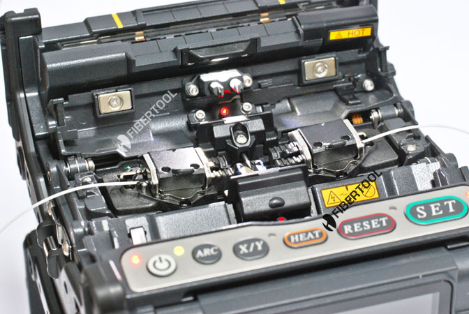
Перед использованием сварочный аппарат необходимо настроить. Сегодня вы узнаете, как настроить аппарат Fujikura 80S.
Для успешного освоения материала рекомендуем вам изучить следующие понятия:
Инструмент для снятия внешней оболочки кабеля
Специальный нагреватель для усадки гильз КДЗС, часто конструктивно объединен с аппаратом для сварки оптических волокон
Один из видов электрического разряда, используемый для расплавления торцов оптических волокон при их сварке

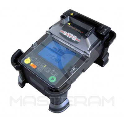
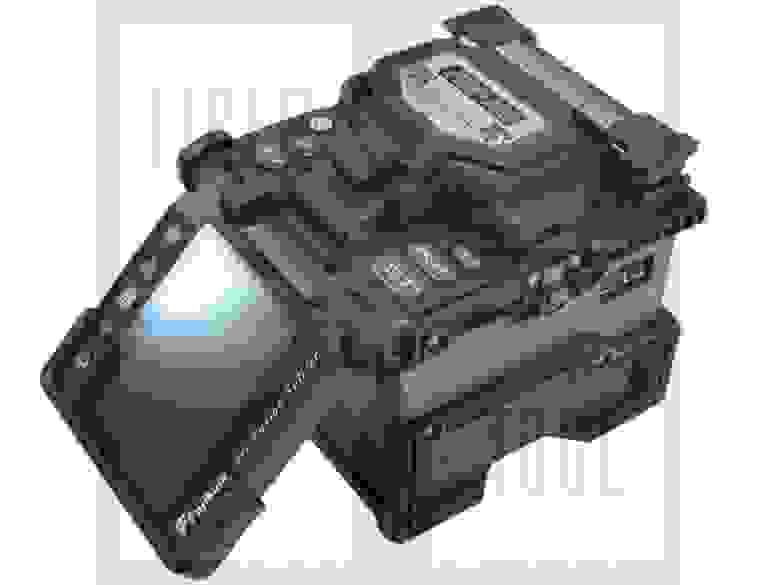
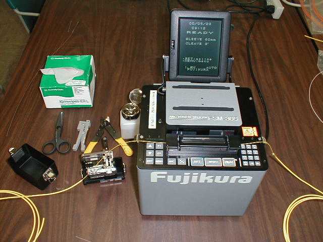
Сварочный аппарат Fujikura 80S


Безворсовые проспиртованные салфетки


Стриппер для снятия буферного или акрилового покрытия


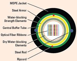
Волоконно-оптический кабель
1. Фиксируем кабель.
2. С помощью стриппера Ideal производим круговой надрез на требуемой длине, чтобы снять внешнюю оболочку.
3. С помощью бокорезов срезаем кевларовые нити.
Настройка и калибровка дуги
1. Заходим в меню.
2. Выбираем кнопку «Следующая страница».
3. Переходим в раздел «Профилактика».
4. Нажимаем «ОК».
5. Выбираем кнопку «Следующая страница».
6. Спускаемся вниз с помощью стрелок и выбираем «Калибровка дуги».
Пробная сварка и усадка гильзы КДЗС
1. Готовим волокна и устанавливаем в сварочный аппарат.
2. Ожидаем выполнения данной операции.
3. «Калибровка моторов», так же готовим волокна и устанавливаем в сварочный аппарат.
4. Ожидаем выполнения данной операции.
После профилактики нужно выбрать режим сварки (это зависит от типа волокна).
- Переходим в меню.
- Нажимаем «ОК».
- Выбираем режим сварки.
Переходим в настройки нагревателя и выбираем режим, который нам подходит.
Важно
Не забудьте при настройке выбрать температуру и время усадки КДЗС (это зависит от длины и типа КДЗС)
Чтобы проверить, насколько правильно мы настроили и подготовили сварочный аппарат перед монтажом, требуется произвести пробные сварки волокон и усадки гильзы КДЗС.
“
На этом уроке мы с вами научились правильно настраивать сварочный аппарат Fujikura 80S. Будьте внимательны! Если вы настроите его неправильно, то соединения могут быть с большими потерями или вы получите неправильно усаженные гильзы КДЗС. Чтобы закрепить полученные знания, предлагаем вам выполнить несколько заданий.
Для закрепления полученных знаний пройдите тест
Что требуется перед началом работы?
Калибровка дуги и моторов
От чего зависит выбор режима нагревателя?
В каком разделе можно сделать калибровку дуги и моторов?
Что влияет на выбор режима сварки?
Количество модулей в кабеле
Что потребуется для калибровки дуги и моторов?
Подготовить оптические волокна
Передвинуть моторы в настройках
Очистить оптический кабель
К сожалению, вы ответили неправильно на все вопросы
Прочитайте лекцию и посмотрите видео еще раз
К сожалению, вы ответили неправильно на большинство вопросов
Прочитайте лекцию и посмотрите видео еще раз
К сожалению, вы ответили неправильно на большинство вопросов
Прочитайте лекцию и посмотрите видео еще раз
Но можно лучше. Прочитайте лекцию и посмотрите видео еще раз
Но можно лучше. Прочитайте лекцию и посмотрите видео еще раз
Вы отлично справились. Теперь можете ознакомиться с другими компетенциями
Обломанное оптическое волокно под микроскопом
Здравствуйте, читатели Хабра!
В этой второй части своего рассказа я продолжаю описывать премудрости работы с оптоволокном. Я, в меру своего опыта и знаний, ознакомлю вас со сварочными аппаратами для оптики, расскажу про скалыватели, коснусь механического метода сращивания волокон. И, наконец, будет описание самого процесса сварки с видео, процесса укладки волокон и обзор результатов. В конце — небольшой бонус: сделанные мною анимации из серий фотографий волокон под микроскопом.
В первой части я рассказывал про кабели и их разделку, оптический инструмент, муфты и кроссы, коннекторы и адаптеры.
Часть 1 здесь
Часть 3 здесь
Осторожно: много текста и трафика!
Сварочные аппараты
Новейшая Fujukura FSM-80S с открытой крышкой и заложенными волокнами. Fibertool
Что у сварочного аппарата под крышкой
Сварочный аппарат для оптических волокон (arc fusion splicer) — один из самых дорогих и сложных (наряду с рефлектометром) инструментов спайщика. Это умный прибор, который берёт на себя весь процесс сведения (юстировки) и сварки волокон, спайщику остаётся лишь подготовить их и заложить в аппарат, а затем достать, надвинуть термоусадочную гильзу КДЗС и заложить в печку. Вкратце принцип работы любого современного сварочного аппарат таков:
1) Очищенные, сколотые волокна с заранее надетой защитной гильзой КДЗС закладываются спайщиком в аппарат, фиксируясь зажимами.
2) Аппарат сам (или по нажатию кнопки) начинает их сводить, пока не увидит в оптическую систему, состоящую из камер-микроскопов и зеркал на внутренней поверхности крышки.
3) Когда оба волокна в поле зрения камер, аппарат даёт короткую слабую дугу, «сдувающую» с волокон микропылинки, которые обычно остаются несмотря на любую протирку. Есть мнение, что эта короткая дуга также чуть-чуть «оплавляет» волокна, подготавливая их к сварке. Если на волокнах была несгораемая и несдуваемая грязь (например, гидрофоб или жир с пальцев), то эта дуга только «запечёт» эту грязь, да так, что никакая протирка не поможет, только переделывать скол.
4) Если волокна чистые и сколы хорошие, он начинает их сводить прецизионными моторами по трём координатам — сначала грубо, потом точно. Если с волокнами непорядок — говорит нам об этом (пишет на экране и подаёт сигнал писком) и отказывается продолжать варить.
5) Когда волокна сведены и подвинуты почти вплотную друг ко другу, где-то на секунду-две включается основная мощная дуга, в которой волокна разогреваются, и в разогретом виде ещё чуть-чуть досводятся друг с другом, чтобы спаяться. После выключения дуги место сварки за долю секунды остывает.
6) Аппарат оценивает по картинке, нет ли косяка (хорошую сварку практически не видно), а также на просвет пытается примерно определить затухание на получившейся сварке. Информация о сварке (дата, время, затухание) сохраняется в памяти, необнуляемый счётчик сварок увеличивается на единицу.
7) Аппарат с дозированным усилием пытается развести сваренные волокна обратно, если при этом сварка не порвалась — тест прочности пройден. Многие его отключают за ненадобностью, ходят даже слухи, что он может подпортить ещё не остывшую сварку.

9) Когда таймер печки вышел, волокно с горячей КДЗС достаётся и КДЗС кладётся на специальную полочку для охлаждения. Если положить её на стол, горячий пластик прилипнет. В горячем виде запихивать в ложемент на кассете нельзя — легко сломать волокно под ещё мягким пластиком.
Про внутреннее устройство, аппаратную и программную части я, к сожалению, не смогу ничего рассказать: никогда не приходилось ни разбирать сварочник, ни подключать к компьютеру. Могу только поклониться электронщикам, механикам и оптикам, создавшим столь сложное и прецизионное устройство, и программистам, написавшим алгоритмы для работы с изображением волокон.
На рынке сегодня ситуация такова: лучшие сварочные аппараты делают японцы (Fujikura, Sumitomo), на пятки им наступают китайцы (Jilong и другие). Так сложилось, что в России Фуджикуры распространены больше Сумитом и Фителов (моё субъективное мнение).
Цена современного сварочного аппарата, которым можно паять ответственные магистральные линии, немаленькая: она начинается с 120-130 тысяч рублей за китайский (за набор — kit), а хороший японский стоит около 300-350 тысяч рублей за набор. В «китовый» набор обычно входит сам сварочный аппарат, кейс, блок питания, скалыватель, стриппер для волокон, иногда дополнительный аккумулятор, полочка для складывания и остуживания усаженных волокон, пинцеты/кисточки/проволочки для чистки, ремень для переноски кейса, кабели для подключения к компьютеру, диск с ПО и прочее. Из бумаг обычно бывает инструкция, результаты выходных испытаний и декларация о соответствии.
Сварочные аппараты можно примерно классифицировать по назначению. На достоверную и всестороннюю классификацию не претендую, но всё же попробую.
1) Для качественной сварки одиночных волокон. Такие аппараты производят юстировку (взаимное выравнивание) волокон на просвет и по оболочке, и по сердцевине, ориентируясь по картинке с двух стоящих под углом 90 градусов камер с микроскопами (метод PAS — Profile Alignment System). Этот метод предпочтительнее, чем устаревший метод выравнивания по одной только оболочке — ведь волокно может быть с эксцентриситетом, немного овальным или с некоторым осевым смещением центрального 9-микрометрового сердечника. Сервомоторы в таких аппаратах обычно могут двигать волокна «к друг другу — от друг друга», «вниз-вверх», «вперёд-назад», кроме того, микроскопы на камерах могут менять фокус для точной фокусировки. Вращать волокно вдоль продольной оси или наклонять на какой-то угол для компенсации отклонения угла скола от нормы современные сварочники не умеют.
Это дорогие, но качественные и, наверное, самые распространённые аппараты, за счёт своей универсальности и качества. Умеют производить примерную оценку величины затухания на сварке, высчитывая её по хитрому алгоритму по изображению сварки на экране. Многие модели умеют сваривать волокна специально со смещением, чтобы сварка получилась с заданным затуханием, когда нужно получить аттенюатор. Примеры — вся лнейка японских аппаратов Fujikura от FSM-30S до FSM-80S, Sumitomo Type-39 (и друге), Furukawa Fitel S178A, с некоторой натяжкой — китайские Jilong KL-260C, KL-280, KL-300/300T и некоторые другие китайцы.
Fujikura FSM-60S
Sumitomo Type-39 Masteram
Jilong KL-300T
Furukawa-Fitel-S178A
2) Вариант «подешевле» для сварки менее ответственных и которких линий, где за затуханием на сварке не так гонятся. Такой сварочник сводит волокна не по сердцевине, смотря на изображение с камер, а просто сдвигая по двум особо ровным V-образным канавкам, то есть многих сервомоторов там нет. Камера и экран лишь для контроля оператором и примерной оценки потерь. Подразумевается, что пользователь будет часто паять многомод. Понятно, что точность сведения и качество сварки будут статистически хуже, так как малейшая пылинка, несовершенство и неотцентрованность самих оптических волокон или микроцарапинка на канавке резко ухудшает соосность сердечников в волокнах и соответственно качество сварки. Цена ниже, чем у «профессиональных» японцев, но выше или сравнима с «профессиональными» китайцами. Поэтому я лично не вижу смысла брать такой аппарат. Пример — Fujikura FSM-18S, Fujikura FSM-17S, возможно — Sumitomo Type-46.
Fujikura FSM-18S. Похож на «шестидесятку». Fibertool
3) Сварочные аппараты для групповой сварки ленточных (ribbon) волокон. В России их почти что нет, как нет и соответствующих кабелей, и прочего оборудования (соответствующие скалыватели, термострипперы). Кабель такого стандарта внутри в сечении прямоугольный, и в нём лежат ленты, составленные из нескольких (обычно до 12) волокон.
Кабель с ленточными волокнами
Готовый комплет пиг-тейлов для кросса, объединённых в ленту. Одна сварка — и кросс на 12 портов сварен. Здорово, правда?
Такой сварочный аппарат варит сразу всю ленту, сильно экономя время. Долгое время Фуджикура в России делала вид, что этих аппаратов вообще не существует. Вживую никогда такие сварочные аппараты не видел, точно принципов зачистки, сведения и сварки не знаю и сказать о них ничего не могу. Не могу также точно сказать, могут ли они варить одиночные волокна как простые сварочные аппараты. Покупать в России смысла не вижу.
Fujikura FSM-60R
Sumitomo Type-66 Ribbon
4) Прочие аппараты «второго эшелона», предназначенные для сварки FTTx-сетей, например, Sumitomo TYPE-25 и TYPE-25e. Границу с группой №2 провести трудновато. Конструкция менее продвинутая и качество сварки не такое высокое, как у «магистральных» аппаратов, аккумулятор слабее, но габариты и цена ниже. Сюда же, за не очень высокое качество, можно отнести дешёвые китайские аппараты, такие, как DVP-730, Jilong KL-260C и другие.
Fujukura FSM-12S
DVP-730 со скалывателем и стриппером
Sumitomo Type-25e
5) Специальные и лабораторные сварочные аппараты для сварки специальных волокон, например, волокон с сохранением поляризации (Fujikura FSM-100M, FSM-100P, FSM-45F). Такие аппараты очень дорогие, имеют кучу гибких настроек, требуют специальных скалывателей. Как вам, например, возможность сделать сколы под углом 45 градусов и так сварить?
Fujikura FSM-100P
Fujikura FSM-45F
6) Старые советские аппараты. Имели некоторое значение в 90-х, когда массовая оптика только начиналась и ими можно было как-то сварить многомод «лишь бы работало». Сейчас неактуальны, так как варят с большим по современным меркам затуханием (лучше 0,2 дБ сварку на одномоде и 0,1 на многомоде вряд ли возможно сделать), сварка очень сложна и неудобна (сведение под оптическим микроскопом вручную, дуга горит, пока держишь кнопку, «доводку» волокон для их спаивания в момент горения дуги нужно сделать вручную с более чем ювелирной точностью, и пр.), вероятность того, что следующая сварка будет удачной, мала, имеют большой вес и габариты, нет запчастей и сервиса, родной скалыватель — не скалыватель, а просто комплект из лезвия и резинки в виде параллелепипеда, они не рассчитаны на современные волокна, и пр. Примеры — КСС-111, Сова. КСС — это полный хардкор, всё вручную и на глаз. В Сове уже можно было юстировать волокна по уровню сигнала: перед и после местом стыковки волокна в зажимах изгибались и по принципу бокового ввода в одном из зажимов на изгиб светила лампа, в другом зажиме около изгиба стоял фотодиод. Когда ток с фотодиода максимальный — стало быть, сердечники волокон совпали лучше всего и можно варить. Правда, сам я на таких аппаратах не работал, может быть тот, кто работал, в чём-то меня опровергнет.
Вот несколько фотографий раздолбанного КСС-111, который стоит в моём университете.
Лично я работал на всех Фуджикурах от FSM-30S до FSM-60S, несколько волокон сварил на обучении на «урезанном» FSM-18S (который со сведением по V-канавке), несколько — на каком-то Sumitomo (наверное, Type-39 — уже не помню). А последние годы я работаю на китайском сварочном аппарате Jilong KL-280. Вот про эти аппараты я в основном и буду рассказывать.
У каждого аппарата есть свои особенности, свои сильные стороны. Это может быть гарантированно высокое качество, или высокая скорость сварки, или скорость усадки КДЗС, или наличие двух печек для КДЗС, или наличие дополнительных удобных фич, или сенсорный экран, или продублированные кнопки управления для удобной работы вдвоём, или супер-увеличение места сварки, или сверхкомпактность, или защищённость от ударов, мороси и ветра, или просто выгодная цена. Например, Fujikura FSM-60S — признанный лидер, задавший новую планку качеству, удобству и скорости работы, он не боится влаги, пыли и умеренных ударов, он относительно компактный, можно тонко настроить его поведение как нужно, но цена кусается, дорогие запчасти и обслуживание. (Недавно вышла новая Фуджикура — FSM-80S, вероятно, она совершеннее «шестидесятки», но я её вживую не видел и сказать про неё нечего). Китайский DVP-730, например, медленнее, менее надёжный, по слухам камеры могут разбалансироваться от тряски в багажнике, но цена втрое (!) ниже фуджикур. А вот Jilong KL-300T — по мнению многих, оптимальный вариант: по сути переработанный клон Fujikura FSM-50S, стоит значительно дешевле Фуджикур и Сумитом, обладает хорошей надёжностью, варит почти так же качественно, как фуджикуровские флагманы. А если кому-то нужна компактность? Тогда его выбор — Furukawa Fitel, или попроще — Fujikura FSM-12S. Словом, для каждой задачи найдётся наиболее подходящий вариант.
Почему же при таком разнообразии многие стремятся, несмотря на цену, купить дорогой сварочный аппарат, желательно японца-флагмана, который предназначен для сварки магистралей?
Я полагаю, дело в универсальности (кто знает, что придётся завтра варить — магистраль, FTTx, PON?), а также в том, что возможно встретить некоторое недопонимание с работниками заказчика, отвечающими за приёмку построенного объекта. С технической точки зрения ясно, что если для сети типа FTTB с её небольшими расстояниями или для коротких линий на десяток километров затухания на сварках не особо критичны, то для магистралей под сотню километров потеря 0,15 дБ на сварке — это уже криминал. Однако те, кто принимает работы, особенно крупные заказчики, зачастую ничего не хотят слышать и требуют, чтоб любая линия (не волокно, а вся готовая линия от кросса до кросса) укладывалась в показатели по затуханию не хуже 0,22 дБ/км затухания на длине волны 1550 нм и 0,36 дБ/км на 1310 нм, и поблажек особо не дают. С одной стороны их можно понять — ведь теоретически через нашу короткую линию могут однажды проключить и ответственную магистраль. Но с другой стороны, всё же порой требования излишне жёсткие. Понятно, что вывести линию на такие показатели с дешёвым сварочным аппаратом намного труднее, чем с хорошим и дорогим. С дорогим ты просто штатно сварил все муфты, возможно, потом после анализа измерений прошёл по муфтам и исправил пару косячков. А с плохим аппаратом можно бегать исправлять затухания очень долго.
Вообще, по моему личному мнению, сейчас самый классный аппарат — это Fujikura FSM-60S. Если б я выбирал для себя и не был стеснён в средствах — я бы выбрал его (правда, вероятно, новейший FSM-80S ещё лучше: там, например, заявлена фича с автоматически закрывающейся после закладки волокон крышкой, что экономит время). Если же денег не хватило бы, я взял бы или Jilong KL-280 (лично проверенный, неплохой аппарат, варит качественно, минусы — немного габаритнее, медленнее и неудобнее фуджикур, не умеет варить сварки-аттенюаторы с заданным затуханием, нет специально заточенных программ для сварки «смещёнки» и новых «сверхгибких» волокон, и до меня доходили слухи о его недостаточной надёжности) или Jilong KL-300T (его в интернете хвалят за надёжность, достаточно высокое качество сварок и за то, что это большой шаг вперёд для компании Nanjing Jilong по сравнению с прежними KL-280 и KL-260C, но я сам его не щупал).
Jilong KL-280
Как вариант можно рассмотреть б/у Фуджикуры 50S или 60S, но б/у есть б/у, можно нарваться на аппарат с каким-нибудь скрытым, трудновоспроизводимым дефектом, да и гарантии нет (как говорит мой папа, какой дурак продаст тебе хорошее?), а покупка такого дорогого инструмента — это всё-таки не покупка мобильника с рук. Аппараты FSM-30S, FSM-40S и прочие старые я бы не покупал, даже попадись новый экземпляр, завалявшийся на складе: цена на них будет почти такая же, как на современные японские флагманы, слишком они медленные, старые, с электродами и запчастями могут возникнуть проблемы, аккумуляторы там никель-металлгидридные (вместо литий-полимерных или литий-ионных на современных аппаратах) и слабые.
Fujikura FSM-20CS: демон древнего мира!
FSM-30S. Медленный, старый, для сварки нужно много движений, но варит вроде неплохо.
Конечно, картина у меня не самая полная; для полной картины мне нужно бы поварить на Sumitomo (тоже отличные японские аппараты) и Furukawa Fitel, на INNO Instrument, а также на других китайцах. Полную картину мог бы дать или спайщик из крупной фирмы с большим парком разных аппаратов, или тот, кто их продаёт.
Сварочный аппарат нужно беречь. Думаю, это очевидно, помня, сколько он стоит. Если вы покупаете аппарат, а работать на нём будут другие — нужно это внушить будущим работникам. Беречь его нужно фанатично, как зеницу ока! Обдумывать каждый шаг. Надёжно ли он стоит? Надёжно ли стоит рабочий столик? Не упадёт ли на него что-то сверху? Не накинет ли порыв ветра вот эту пыль с дороги на рабочее место? Не собирается ли гроза? Если собирается, взял ли я палатку? А что будет, если кто-то из прохожих дёрнет за торчащий из рабочей палатки свариваемый кабель, не упадёт ли от этого сварочник? Не захотят ли вот те ребята в туфлях и спортивных костюмах познакомиться поближе со сваркой оптоволокна? И так далее. Я всегда стараюсь садиться за сварочный аппарат с таким же чувством, с каким в начале 2000-х, будучи школьником без денег, в первый раз взял в руки мобильный телефон… 
Испытания Фуджикуры FSM-60S пылью и водой
То же самое касается скалывателя: основу скалывателя, наподобие корпусов жёстких дисков, делают из мягкого металла и покрывают легко сдирающейся краской или анодированием/воронением, и это неспроста. Его нельзя бить или ронять. Будет вмятина и содранная краска — гарантии конец. Нельзя также касаться кругового ножа пальцами и прочими предметами, волокна нужно закладывать очень осторожно, одно движение кривыми руками может повлечь порез пальца и минус ресурса в несколько тысяч сколов (если нож частично затупится). За этим также нужно внимательно и фанатично следить. Нельзя, чтоб он ржавел в сырости. Я и напарник можем гордиться: наш скалыватель за 3 года экстремальных чердачно-подвальных условий ни разу не падал.
Сварочному аппарату также периодически нужно делать обслуживание разного «уровня»: минимум — делать очистку электродов мощным током, калибровку положения дуги и калибровку силы тока в дуге. Всё это делается программно, через меню, и всё описано в инструкции. Так обстоит дело с нынешним нашим Jilong’ом KL-280, у японцев немного по-другому, там есть отдельные программы самотестирования. Эти тесты желательно прогонять каждый раз перед началом работы, если после предыдущей калибровки изменилась температура/влажность воздуха (влияет на дугу) или с прошлой калибровки было сделано много сварок (кончики электродов успели немного износиться).
Иногда требуют замены электроды (после нескольких тысяч сварок) и аккумулятор. Иногда требуется чистка от пыли (кстати, продувать баллончиком со сжатым воздухом запрещается — слишком чувствительная механика). Иногда что-то ломается, разъюстируется, и требуется полноценный ремонт в сервис-центре. На некоторых китайцах после 9999 сварок (весьма внушительный объём) аппарат блокируется, требуя нести его в сервис-центр для полного обслуживания.
Что касается электродов, то есть, конечно, рекомендуемые производителем аппарата объёмы сварок, после которых электроды лучше поменять. Однако по факту многие спайщики варят до упора, пока не начнутся плохие сварки и нестабильная дуга. С электродами есть маленький секрет: можно продлить их жизнь ещё на несколько сотен сварок. Дело в том, что износ электродов — штука комплексная. Отчасти он заключается в том, что на электроды постепенно напыляется слой стекла со свариваемых волокон. Отчасти — в выгорании «воронок» на кончиках электродов, что приводит к нестабильной дуге. Так вот, крошки напылённого стекла можно сковырнуть бритвой, то, что осталось — снять чисткой в стирательной резинке. Только резинку нужно выбирать «нежную», без абразивных элементов, иначе электроды придётся выбросить почти сразу.
После замены электродов нужно обязательно прогонять соответствующую калибровку.
Электроды для сварочного аппарата
Вот мы ознакомились с тем, что такое современный аппарат для пайки оптоволокна, какие эти аппараты бывают. Более подробно вернёмся к описанию его работы, когда далее сварим, усадим и уложим волокно. А сейчас познакомимся со скалывателями оптических волокон.
Скалыватели
Устройство оптического скалывателя
Скалыватель (cleaver) — это механическое прецизионное устройство, задача которого — сколоть конец оптического волокна так, чтобы плоскость скола была как можно ровнее и как можно перпендикулярнее самому волокну. Хотя существуют специализированные скалыватели и с электроникой, и позволяющие делать углы скола отличные от 90 градусов, я их рассматривать здесь не стану.
Качество скалывателя определяется по таким статистическим параметрам: насколько ровный скол получается, насколько угол плоскости скола отличается от 90 градусов, насколько часто скалыватель ломает волокна, насколько удобно с ним работать, каков ресурс.
Зачем нужен скалыватель? Если мы просто отломаем кончик волокна пинцетом, то вероятность хорошего скола будет крайне мала, и сварка гарантированно не получится. Вот пара примеров плохих сколов (а также картинка в шапке статьи):
Плохой скол на экране сварочника (вид одного и того же волокна с двух камер). На экране рабочая пыль и царапинки. 
Левое волокно с плохим сколом, правое — нормальное (небольшой чёрный дефект, что на правом волокне — частое явление, он обычно не оказывает влияния на сварку, так как расположен с краю волокна).
А сварка (если мы всё-таки заставим умный сварочник, несмотря на протесты, принудительно сварить) — будет выглядеть как-то так:
Типичный «пузырь». Сварка подлежит переделыванию. Работать линия с такой сваркой не будет. В лучшем случае, если линия короткая, поднимется с кучей потерь пакетов, но затухание тут будет несколько децибел.
Поэтому нам нужен специальный инструмент, чтобы аккуратно подготовить волокна к сварке.
Скалыватели, как и сварочные аппараты, бывают разные. Подороже, подешевле, сильно подешевле, узкоспециальные, исторические. С контейнером для сколотых волокон и без такого. Полноценный обзор всех существующих скалывателей я дать, пожалуй, не смогу, так как работал всего с двумя моделями. Так что опишу то, с чем работал. Если вкратце — моё мнение такое: если со сварочником можно пойти на компромисс и сэкономить около сотни тысяч рублей, купив хорошего «китайца» вместо японца, то со скалывателем этого лучше не делать. Да, да: купив китайский «кит» с прилагающимся китайским скалываталем, я советую докупить дополнительно хороший японский скалыватель, а «китовый» скалыватель использовать как резервный (или как дополнительный, для ускорения работы). Хороший скол — это уже 50% удачной сварки, а быстрота и удобство в работе — залог того, что спайщик за день успеет сварить больше. Так что вложив лишних 20-30 тысяч, не сильно заметных на фоне стоимости сварочного аппарата, рефлектометра, автомашины и прочего оборудования, мы увеличим и удобство, и качество, и скорость работы спайщика. Хотя, конечно, если цель — сформировать мини-бригаду для обслуживания провайдерской сети при минимальном бюджете, где удобство, скорость работы и качество на втором плане, и строить первоклассные магистрали не планируется — можно и сэкономить, используя стоковый китовый скалыватель.
Вот немного примеров в картинках.
Советский скалыватель! Лезвие, резинка, чехол и инструкция. Бритвы — в дополнение. Спасибо начальнику, что сохранил такой артефакт. Такие толстые волокна, кстати, держать в руках не приходилось. Попытался ради опыта аналогичным образом (новое лезвие и мягкая стирательная резинка) сколоть современное волокно — попытка не удалась.
Jilong KL-21C во время чистки
Fujikura CT-30
Скалыватели INNO Dragon. С нанесённым рисунком!
Опишу первый скалыватель, которым я работал. Это — пример хорошего, проверенного временем скалывателя. Это Fujikura CT-30/CT-30A.
Очень у многих спайщиков имеется именно эта модель. Я с таким работал и скажу, что это действительно хорошее, продуманное и удобное устройство. Он компактный, надёжный, для скола нужно минимум движений, от него не приходится ждать неожиданностей. Только надо брать обязательно с контейнером для сколотых волокон. К сожалению, моё начальство не покупает мне его, приходится работать на китайском. Есть и другие модели фуджикуровских скалывателей, которые позиционируются как более современная, компактная и дешёвая, но отнюдь не менее качественная замена CT-30A. Но всё равно CT-30A – это классика.
Другой скалыватель, на котором я работал и который у меня сейчас — это китайский Jilong KL-21C, который был в наборе со сварочным аппаратом Jilong KL-280. Свою задачу этот скалыватель выполняет, но у меня к нему есть ряд претензий. Например: количество действий, которое нужно произвести для скола. У китайца оно больше, чем у японца. В случае CT-30A нам требуется:
1. Взвести каретку с ножом.
2. Заложить волокно.
3. Закрыть фиксатор волокна.
4. Нажать на крышку, произведя скол.
5. Открыть фиксатор.
6. Достать сколотое волокно.
В некоторых скалывателях нужно ещё меньше действий: даже взводить каретку не нужно, она взводится при открывании крышки и производит рабочий проход при её закрытии.
В случае же KL-21 нужно:
1. Взвести каретку с ножом.
2. Заложить волокно.
3. Закрыть фиксатор волокна.
4. Закрыть крышку.
5. Вручную протолкнуть каретку с ножом, произведя скол.
6. Открыть крышку, преодолев силу магнитов (одной рукой неудобно).
7. Открыть фиксатор.
8. Достать сколотое волокно.
Казалось бы, всего 2 лишних действия. Но это — эргономика, это — время, это — объём работы, который за рабочий день может быть больше, если все операции делаются быстро.
Потом, этот скалыватель порой ломает волокна, причём чистка, продувка особо не помогают. Двадцать раз сколол нормально, на двадцать первый достаёшь волокно — а оно сломалось в каком-то одном из нескольких «любимых» скалывателем мест: перед или после резиновой подушечки, или между подушечкой и ножом. Приходится зачищать и протирать спиртом заново. Вполне допускаю, что кто-то с этим не сталкивался, но факт есть факт.
На холоде и в сырости по не до конца понятным мне причинам начинает колоть хуже и волокна ломать чаще. Доходило до того, что стоишь ночью на обочине дороги в грязи под снегом с дождём, весь мокрый и злой, на капоте машины разложена почти сваренная муфта, которую надо обязательно доделать, не менее продрогший товарищ одной рукой с картонкой прикрывает сварочник от осадков, второй рукой светит фонариком, и тут как назло 2 волокна из 3х ломаются и приходится их переделывать задубевшими пальцами.
Ресурс кругового 16-позиционного ножа у китайского скалывателя довольно маленький: приходится часто (по сравнению с фуджикуровским) поворачивать на следующую позицию, иначе начинает плохо колоть. Когда нож прошёл полный оборот, его соответствующим регулировочным винтом поднимают на какие-то микроны и он проходит второй оборот. После этого — второе поднятие и третий оборот, потом замена ножа.
Полный ресурс хорошего японского скалывателя — где-то 48000 сколов. Вот что значит японская сталь! 
Круговые ножи для всевозможных скалывателей. Взаимный масштаб не соблюдён.
Есть и другие скалыватели. Например, дешёвые недо-скалыватели в виде прищепки, которые не обеспечивают точной перпендикулярности скола и которые я бы не советовал применять.
Принцип работы скалывателя такой:
1. Волокно (зачищенное от лака и протёртое от грязи) должно быть хорошо зафиксировано.
2. В момент скалывания на волокне алмазным ножом или ножом из твёрдой стали делается поперечная микроцарапина.
3. К волокну прикладывается такое усилие, чтобы оно треснуло аккурат по поцарапанному месту.
В разных моделях технология произведения этих операций немного разная, и наглядно показать процесс скалывания я не смогу (для этого пришлось бы в каком-нибудь 3DS MAX’е рисовать замедленную полупрозрачную 3D-анимацию процесса скалывания, где каждая деталь подкрашена своим цветом). Но объяснить в общих чертах и показать на видео попробую.
Рассмотрим подробнее скол одного волокна на типичном скалывателе.
1. Оптическое волокно зачищено на определённую длину, хорошо протёрто безворсовой салфеткой со спиртом. Пальцами стекла не касаемся!
2. Открываем фиксатор и крышку и осторожно закладываем волокно в скалыватель. Волокно при этом важно не запачкать и пальцами не влезть в нож! Волокна в лаковой оболочке закладываются в тонкую канавку, а пиг-тейлы в жёлтой оболочке — в толстую. Закладывать совсем толстые патч-корды нельзя; если надо сварить патч-корд — его нужно разделать как кабель, освободив волокно.
3. Волокно должно быть заложено так, чтобы граница между лаковым покрытием и голым стеклом легла на нужную нам цифру на линейке. Эта цифра говорит нам, сколько миллиметров голого стекла будет торчать из лака после скола. Для каждого сварочного аппарата эта цифра своя (например, для нашего Jilong’а KL-280 это 16 мм), надо её просто запомнить для своего аппарата. Если заложить так, что сколется меньшая длина — сварочнику не хватит диапазона подачи кареток, чтобы свести волокна, и он запищит и выведет на экран ошибку «Предел подачи» или «Заново уложите волокно». Если сколоть так, что стекла наоборот останется слишком много — всё сколется и сварится нормально, только вот защитная гильза-КДЗС (если она «короткого» стандарта 40 или 45 мм) может по длине оказаться короче, чем голый стеклянный участок волокна, и не защитить полностью оголённое волокно. В этом случае волокно без защитного лака очень легко сломается от изгиба на выходе из КДЗС (при той же укладке), и такую сварку нужно переделать.
4. Производим скол. В каких-то моделях для этого достаточно нажать на крышку скалывателя, в каких-то надо её закрыть, толкнуть пальцем каретку и снова открыть.
5. Открываем фиксатор, если надо — крышку и осторожно достаём сколотое волокно. Сразу, ещё не доставая, можно понять, не сломалось ли оно. Его теперь нельзя никуда класть, кроме как в сварочный аппарат, потому что стоит коснуться им чего угодно — оно сразу станет грязным. В сварочный аппарат его также надо закладывать таким образом, чтоб не зацепить кончиком никаких деталей и поверхностей: стоит случайно ткнуть торцом сколотого волокна в ту же V-канавку или в электрод при закладке в сварочник — и при сведении волокон вы увидите на этом волокне тонну грязи. 
Волокна грязные, кроме этого к волокну прилипла большая пылинка
Такое выпачканное волокно, в принципе, можно попытаться очистить — сначала просто протереть салфеткой, а потом потыкать торцом в спиртовую, а затем в сухую салфетку. Вероятность процентов 60, что оно после этого будет чистым и хорошо сварится. Но всё же лучше его сразу перезачистить и переколоть, а ещё лучше — не ронять и не пачкать протёртые и сколотые волокна.
6. Сколотый кончик волокна, в зависимости от конструкции скалывателя, сам затягивается в контейнер для волокон, остаётся торчать в «валиках» или, если нет контейнера, падает на стол рядом со скалывателем. Соответственно в первом случае нужно просто проконтролировать, нормально ли затянуло волокно в контейнер (слишком длинное не поместится, поэтому зачищать волокна от лака по 10 см не нужно; иногда волокно может как-то соскочить и не затянуться в контейнер), во втором надо специальной ручкой прокрутить валики, чтоб волокно втянуло меж валиков в контейнер как бельё при отжиме в старой стиральной машине, а в третьем — тут же приложить к волокну кусочек изоленты, чтобы волокно к нему прилипло, а потом обклеить эти прилипшие к изоленте волокна со всех сторон. Вообще пользоваться скалывателем без контейнера для волокон КРАЙНЕ не рекомендую, и вот почему.
Кусочки оптического волокна, особенно без лака — это опасный отход производства. В странах с лучшей культурой переработки отходов их собирают и утилизируют. У нас, конечно, как придётся, но всё равно это не повод разбрасывать после себя волокна. Все осколки волокон нужно тщательно собирать! Если такой едва заметный кусочек попадёт в еду, в питьё — можно заработать язву желудка или прочие проблемы. Если он вопьётся в тело и сломается — теоретически может по кровотоку дойти до сердца, хотя обычно становится трудноизвлекаемой, очень неприятной занозой, которую никакой рентген не найдёт и которая крошится под пинцетом при попытке её вытащить. Да и просто волокна в одежде, в обуви, в сиденьях машины — не самая приятная вещь. Поэтому:
1. Никакой еды на рабочем месте.
2. Все волокна до последнего необходимо тщательно собирать. Даже если работа производится где-нибудь в полузатопленном канализацией подвале, где по колено мусора и блох, или в поле по колено в грязи — это не повод мусорить волокнами!
3. Скалыватель — только с контейнером для сколотых волокон.
4. По-хорошему следует пользоваться средствами защиты: очками, спецовкой, фартуком. Но этого никто не делает.
Я лично, когда приходит время чистить контейнер скалывателя от накопившихся кусочков сколотых волокон, сажусь за стол, стелю себе большой лист бумаги и над ним ссыпаю их в отдельную бутылочку, а потом тщательно собираю то, что упало.
Вот радость-то будет врагам в ботинки высыпать!..
Однако вернёмся к скалывателям.
Сами понимаете, что успешный скол зависит от микронов. Поэтому скалыватель нужно беречь от ударов, падений, грязи и кривых рук так же ревностно, как и сварочный аппарат. Он не зря упакован в шкатулку с мягким наполнением.
Нельзя крутить настроечные винты, не будучи точно уверенным, что делаешь. Нельзя лазить вовнутрь руками или твёрдыми предметами — есть риск порезаться и загубить заточку лезвия. Нельзя надолго оставлять скалыватель во влажной среде.
Просто нужно помнить: сварочный аппарат, скалыватель и рефлектометр — три незаменимых вещи, без которых работа встанет. Да, можно помучившись разделать кабель обычным ножом вместо НИМ-25. Да, можно снять лак с волокна бритвой вместо стриппера. Но сделать подручными средствами хороший скол малореально, сварить же волокно — невозможно.
Итак, мы вкратце рассмотрели скалыватели и принцип их работы.
Теперь познакомлю вас с механическим сращиванием волокон — и перейдём к подготовке волокон и их сварке.
Механическое сращивание оптических волокон
Механическое сращивание оптических волокон изначально позиционировалось как более дешёвая альтернатива сварным соединениям. Со временем, когда цены на оборудование снизились, а качество волокна и соответственно требования к параметрам линии выросли, механические соединения стали менее актуальны.
Достоинства:
1. Не требуется капитальных вложений в сварочный аппарат (но скалыватель и весь прочий инструмент всё равно нужен).
2. Выше мобильность монтажника оптики — не нужно таскать большой кейс со сварочником.
3. Подходит как дешёвый резервный вариант для временного восстановления связи, когда сварочника рядом нет или там сел аккумулятор посреди поля, а связь нужна немедленно.
4. Обычно механические соединители можно установить в стандартную кассету вместо КДЗС.
5. Один механический соединитель обычно может выдержать несколько перезаделок волокон, а гильза КДЗС одноразовая.
Недостатки:
1. Потери на соединении в любом случае сильно выше, чем в случае сварного стыка.
2. По времени возни требует не меньше, чем со сваркой.
3. Надёжность ниже. Иногда (от вибрации, от времени) соединение может нарушиться, особенно если файбрлоки/корелинки ставились уже б/у, и придётся долго и уныло искать, какой же из этих треклятых файбрлоков на этот раз отвалился.
4. Сварочный аппарат стоит дорого, но потом цена одного сращивания маленькая. С механическими соединителями — наоборот.
5. Для многих заказчиков такой монтаж — это несерьёзно.
Вообще я читал про случаи, когда короткая линия поднималась и почти без потерь пакетов работала, имея на себе 3-4 механических соединения, выполненных вообще без участия скалывателя! Такое возможно лишь благодаря иммерсионному гелю и везению (чтобы сколы были более-менее ровные, а не как наконечник копья). Но всё же это из разряда извращений, для монтажа механических соединителей всё равно необходим нормальный скалыватель. Тогда можно получать на механических соединениях затухания примерно от 0,1 дБ и выше: для магистрали это много, но как временный вариант или для короткой второстепенной линии — сойдёт.
Монтаж соединителя Fibrlok
Стандартов механического сращивания много.
Наверное, самый известный стандарт механического соединения — это «fibrlok».
Приходилось видеть пару раз вживую и даже монтировать (на обучении, правда). Соединитель представляет собой пластиковый параллелепипед, состоящий из трёх частей. Первая часть — это пластмассовое, в сечении U-образное основание-жёлоб. В него вставляется две других части: пластмассовая П-образная в сечении крышка с защёлками и металлическая V-образная в сечении канавка с круглым «ложем» под волокна не дне.
В эту канавку V-образной канавки с обеих сторон вставляются подготовленные сколотые волокна, обычно концы их макаются в специальный иммерсионный гель для снижения потерь и отражений от перехода света из стекла в воздух и опять в стекло. Капелька иммерсионного геля может уже быть внутри файберлока. Показатель преломления у этого геля близок к показателю преломления стекла сердечников волокон. Этот же гель зачастую обладает гидрофобными свойствами.
Сама канавка может немного сгибаться вокруг заложенных волокон, отдалённо похоже на рояльные петли. Когда волокна заложены, сверху на эту канавку одевается П-образная крышка-фиксатор, которая при одевании сжимает V-канавку, плотно фиксируя вставленные волокна, и сама фиксируется защёлками.
Есть и другие стандарты. Например — Corelink, мне его тоже приходилось видеть вживую. Принцип работы похож на Fibrlok, открывается ключиком.
Ещё мне приходилось на первой работе, когда я мало что знал про оптику, видеть монтаж какого-то механического соединителя, который открывался специальным механизмом на идущем в комплекте монтажном микро-столике. Что за соединитель — уже не вспомнить, прошло 5 лет.
Вывод — таких соединителей много стандартов, с собой можно носить десяток файберлоков на всякий случай, но разумно ли их использовать «на постоянку» — большой вопрос. Сварочный аппарат, конечно, недешёвый, но после пары крупных проектов он себя окупит. А механические соединители сами по себе стоят ощутимо, по времени монтируются столько же, как и сварное соединение, затухания и отражения дают больше, надёжность ниже.
Итак, мы рассмотрели сварочные аппараты, скалыватели и механические соединители. Самое время продолжить рассказ про подготовку и сварку оптического волокна.
Подготовка оптических волокон
В первой части мы остановились на том, что разделали кабель, протёрли волокна, подготовили муфту (или собрали кросс) и завели в неё/в него кабель. Продолжаем монтаж. Впрочем, до процесса сварки нужно сделать ещё кое-что важное.
Следующий важнейший шаг — это маркировка модулей и волокон. Собственно, промаркировать кабель следует ещё до ввода в муфту, иначе это будет сделать не так удобно, просто я позабыл в первой части об этом написать. Но маркировать модули нужно обязательно. Если этого не сделать — потом придётся продёргивать, какие волокна в какой модуль идут. Поверьте, это очень неудобно и легко ошибиться.
Для маркировки используются вот такие бумажные или тряпичные наклейки-маркеры.
Они часто продаются в виде блокнотика с такими листами или в виде десяти барабанчиков, на которые накручены ленты с цифрами от 0 до 9. Обычно входят в комплект муфт, реже — в комплект кросса.
Очень распространённая и при этом труднообнаруживаемая и неприятная ошибка новочков (да и опытные порой этим грешат) — это перепутать модули. Красный (первый) и второй модули перепутать трудно, а вот белые/натуральные/бесцветные — запросто, они же одинакового цвета… Это тот самый случай, когда можно в упор не заметить глупой ошибки. Поэтому семь раз проверь — один раз промаркируй и спаяй.
На этих картинках я схематично нарисовал разрезанный кабель и принцип маркировки его модулей, а также показал пример маркировки реального кабеля.
Маркируются модули следующим образом.
У них обычно цветовая маркировка, которая указана в паспорте кабеля. Тем не менее первый модуль — всегда красный, исключений пока не встречал ни разу. Вот мы на чистые протёртые волокна, выходящие из этого первого модуля, сразу и клеим цифру «1».
Следующий модуль будет тот, который «цветной» и стоит около красного. Около красного, безусловно, стоит 2 модуля, слева и справа, но с другой стороны будет или белый (он же натуральный, он же бесцветный — везде по-разному пишут), или чёрный (или тоже белый) модуль-пустышка. Так вот тот, что около красного и «цветной» (обычно жёлтый, зелёный, синий) — будет второй. Клеим на его волокна цифру «2».
Третий модуль может быть в зависимости от кабеля как ещё одним цветным, так и белым/натуральным/бесцветным. Важно понять следующее. Первые два модуля своим расположением уже задали нам направление «обхода» по кругу модулей в кабеле — либо по часовой стрелке, либо против. Вот мы и продолжаем это направление и клеим на волокна следующего модуля цифру «3». Красный — первый, цветной — второй, следующий по повиву — третий. Ещё один следующий по тому же направлению «обхода» по кругу, обычно бесцветный — четвёртый, и так далее.
Всё вот так просто. Но путают модули часто, и найти и устранить это бывает очень непросто: если в линии пара десятков муфт, которые придётся вскрывать, причём многие из них закопаны на пару метров в грунт и над ними уже колосится кукуруза или находится размытая дождями пашня — сами понимаете, какое мучение с лопатами на жаре исправлять такой косяк.
Как найти место, где перепутали модули?
«Перепутка» определяется следующим образом. Предположим, у нас прямая линия: 2 кросса и между ними несколько муфт.
На одном кроссе становится человек с передатчиком оптического излучения длиной 1310 или 1550 нм, на втором кроссе — человек с тестером-приёмником, на котором выставляет ту же длину волны. Ставят и приёмник, и передатчик на первые порты. Если волокна не перепутаны и первый порт на одном кроссе действительно приходит на первый порт второго кросса, тестер покажет некоторый уровень сигнала. И так, созвонившись для координации действий по телефону, «протыкивают» все порты на кроссах.
Кстати: в прежние времена, когда сотовых телефонов ещё не было, а оптику уже тянули, использовались так называемые оптические телефоны: пара трубок с аккумуляторами, настроечными ручками, микрофоном, динамиком и одним или двумя разъёмами FC или LC. Можно поговорить, встав на пару свободных волокон или даже на одно волокно (в этом случае приём на 1310 нм, передача на 1550). Я разок пользовался таким. Сейчас в целом это не нужно, так как, во-первых, есть сотовые, во-вторых на многих мультиплексорах есть встроенный телефон для связи между узлами сети, в-третьих, на многих узлах связи есть городской телефон. Но в принципе может иногда возникнуть необходимость и в таком девайсе.
Оптические телефоны
Вернёмся к поиску «крестов» на линии. Если есть «перепутка» — это сразу становится понятно: начиная с какого-то порта (на нашем рисунке — с пятого) на «передающем» кроссе идёт просто следующий порт, а на втором «приёмном» кроссе сигнала в этом же порте нет, зато он (и последующие n портов) есть в порте со сдвигом на х*n портов, где n — число волокон в модуле, х — число модулей, которые «перескочили» (в нашем случае n=4 волокна в модуле, x=1 (на 1 модуль перескочили): порты с 1 по 4 проходят как надо, а 5-й приходит на 9-й, 6-й на 10-й и так далее.
По-хорошему в случае перепутки надо вскрывать и перебирать все муфты. Можно, конечно, упростить задачу поиска такого косяка: вскрыть муфту посередине линии и вручную проверить её, продёрнув по волокну из каждого модуля. Если на ней перепутки нет, то нужно осторожно (чтоб не сломать) загибать на ней волокна по одному из модуля (скажем, первое из первого модуля, первое из второго модуля и т.д.), а напарник с рефлектометром на кроссе будет смотреть, укоротилась линия или нет. (Помним, что сильно перегнутое волокно теряет излучение на изгибе и дальше сигнал не пропускает). Если укорачиваются именно те волокна, какие и должны — значит, косяк дальше, между вскрытой муфтой и дальним кроссом. Если загибаем, к примеру, волокно из третьего модуля, а короче стало аналогичное волокно с четвёртого модуля — значит, косяк на какой-то муфте между кроссом, где рефлектометр, и вскрытой нами муфтой. Закрываем муфту и едем вскрывать какую-то муфту между кроссом и только что вскрытой до этого и всё повторяем. Для таких работ очень нужно иметь схему распайки и схему линии, на которой будут указаны расстояния от кроссов до всех муфт.
Если схема распайки сложная, в линии много «тройниковых» (или «отпайных») муфт, спаяны кабели с разными цветами волокон и разным количеством их в модулях — задача сильно усложняется. Тут уж придётся собрать мозговой штурм, всерьёз включить мозг и посидеть над схемами, вырабатывая самый оптимальный план поиска муфты с перепуткой.
А вот если в такой сложной линии 2 и более места, где перепутаны модули, то…
… спайщикам нужно больше тренироваться, а не варить сразу большие сложные объекты. И проектировщикам такой сложной схемы распайки можно передать наилучшие пожелания.
Нет — можно, конечно, схалтурить: тупо переткнуть/перекрутить пиг-тейлы изнутри одного из кроссов так, чтобы все порты приходили друг на друга в соответствии со схемой. Но во-первых, заказчик на приёмке может и заглянуть в кроссы, во-вторых, получается, мы сдаём линию, часть которой распаяна непонятно как, а не в соответствии с документацией. Через год часть волокон в линии продадут, часть сдадут в аренду всяким провайдерам, ФСБшникам, транспортникам и прочим организациям. Кому-то потребуется что-то вварить в какую-то из муфт, соответствующий модуль разрежут, чтобы к нему подпаяться, а там окажется, что сигнал идёт не по тем волокнам, по которым должен, и мы разрезали не тот модуль и уронили чей-то магистральный DWDM!!! Который обязательно окажется незарезервированным! Или как вариант окажется, что мы отрубили связь ФСБ. Или уронили сотовую связь на большой территории. Или интернет+телефон с загородной виллы какого-нибудь депутата. Трёхэтажные и продолжительные проклятия от службы эксплуатации в адрес горе-строителей гарантированы! А там как знать, может, в зависимости от ущерба за перерыв связи будет и судебный иск. Да и кто наймёт потом такого подрядчика, сдавшего линию со скрытым дефектом? Не делайте таких вещей своим коллегам-связистам: если уж перепутали модули — надо до сдачи линии найти и исправить.
Бывает лайт-версия перепутки: когда путают не модули, а пару волокон. Например, при плохом освещении запросто можно перепутать белое и серое волокно, серое и бесцветное/прозрачное, белое и светло-розовое, зелёное и бирюзовое и пр. По крайней мере это найти проще: если в муфте в кассете подписано, где какие волокна лежат и куда идут, можно просто открыть муфту и сравнивая со схемой посмотреть, какой цвет на какое волокно разварен. Но если муфты труднодоступны, всё равно радости мало.
Так что вы убедились, как неприятна ошибка с перепутанными модулями или волокнами, и как трудно может быть её исправить. Лучше всё дотошно промаркировать, чем потом бегать по полям с лопатами и трассоискателем или заниматься гимнастикой на опорах с лестницей, откапывая/снимая со столбов муфты, и завалить срок сдачи линии.
Ещё скажу пару слов про случай, когда в кабеле один-единственный модуль и в нём много волокон. Я встречался с таким кабелем Siemens, где маркировка была выполнена следующим образом. Когда снимаем трубку-модуль, перед нами пучок волокон в гидрофобе. Так вот не надо спешить протирать этот гидрофоб. Если попробовать разделить волокна не протирая, выяснится, что они идут двумя или более группами, каждая из которых обёрнута «спиралью» из нитки своего цвета: скажем, синяя и оранжевая нитки. Шаг повива у ниток большой, так что протирая гидрофоб, мы можем легко нарушить ниточную маркировку смешать такие «подмодули», придётся снова разделывать кабель.
Идём дальше.
Волокна на всех кабелях мы промаркировали. Но если мы варим кросс — то мы паяем не кабели между собой, а один кабель развариваем на пиг-тейлы кросса. Я рекомендую эти пиг-тейлы также все промаркировать этими же самоклеящимися циферками. Можно этого и не делать, но придётся во время сварки отвлекать внимание ещё и на то, правильный ли пиг-тейл взят. Конечно, это проще, чем продёргивать непромаркированный модуль кабеля, и в случае ошибки пиг-тейлы на кроссе легко поменять местами: тут это ничем не грозит. Но лучше всё же потратить 10 минут, промаркировать и забыть. Некоторые кроссы идут уже собранные и с промаркированными по порядку (и иногда даже зачищенными) пиг-тейлами, тогда повезло: сэкономим кучу времени и наклейки-маркеры.
Итак, модули/волокна и пигтейлы промаркированы. Теперь мы (уже введя в муфту кабель и закрепив его за косичку из кевлара, под специальный зажим, за силовой центральный элемент или червячным хомутиком к стальной рамке муфты) крепим модули к кассете (заранее продумав, какие модули в какую кассету пойдут). Я предпочитаю подматывать кончики модулей изолентой (но так, чтобы было видно, какого цвета кончик), а затем за подмотанное место уже крепить парой маленьких стяжек к кассете: в этом случае их трудно случайно выдернуть из кассеты, а без изоленты они легко выскакивают из-под стяжки: сила трения покоя пластиков типа лавсана крайне мала. Правда, если модули недостаточно хорошо оттёрты от гидрофоба — изолента к ним не прилипнет.
Следующий этап — отмеривание волокон в кассете.
Они отмеряются путём предварительной укладки в кассету и подрезаются ножницами у центра ложемента для КДЗС, в котором планируется их уложить после сварки.
В некоторых кассетах (например, как на этом снимке), где множество разнонаправленных каналов для волокон, отмеривание волокон в принципе можно не производить — всё равно найдётся «путь» для укладки волокон, чтоб после сварки легло красиво.
Однако в случае сварки большого числа волокон отмерять всё же следует, а путь укладки желательно выбрать самый простой (по кругу), без хитрых сложных петель и переходов по каналам. В обычных же кассетах отмерять нужно обязательно, так как если заранее не отмерить волокна по длине и не продумать, как они лягут в кассету после сварки, при укладке возникнут серьёзные проблемы. В лучшем случае (если останутся значительные запасы и ими получится «сыграть») волокна уложатся, но будут нарушены допустимые радиусы изгиба волокон, что может повлечь повышенное затухание для сигнала, и кассета будет выглядеть некрасиво. В худшем волокна просто не удастся уложить так, чтобы крышка кассеты закрылась и нигде ничего не зажало.
Вот такой кошмар получается, если забыли отмерить волокна: часть волокон внатяг и из-за этого слишком сильно изгибаются (будет затухание на изгибах), некоторые слишком длинные и их приходится класть по маленьким радиусам и фиксировать изолентой.
В том случае, если два волокна, которые предстоит сварить, выходят из модулей, которые заходят в кассету «встречно» друг другу, достаточно каждое из них отмерить путём простой укладки
нескольких (обычно двух) оборотов и отрезать над ложементом, где планируется уложить КДЗС этой сварки.
В том случае, если модули заходят «сонаправленно» (так всегда случается, если в одной кассете варим 3 кабеля), одно из волокон следует отмерить как обычно, второе же волокно следует отмерить с учётом перехода, который осуществляется S-
образной петлёй посередине кассеты.
Вообще вышепоказанной ситуации с S-образным переходом волокон следует избегать и стараться завести модули «встречно», так как, во-первых, не все кассеты рассчитаны на такой переход волокон, и S-образную петлю перехода волокон (а их может быть много) приходится фиксировать в центре кассеты изолентой, что нетехнологично и нежелательно. А во-вторых, это занимает больше времени на отмерку волокон. Если муфта и так сложная, содержит несколько кассет и имеются переходы волокон в трубках между нижними и верхними кассетами, схема разварки запутана, заходит 3-4 или более кабелей, то ситуация чрезмерно усложняется, можно допустить ошибку при монтаже, найти и исправить которую впоследствии будет очень непросто.
Также надо продумать, все ли волокна, которые мы хотим сварить, поместятся в кассету. Рассмотрим несколько случаев.
Самый простой случай — это когда нужно спаять 2 одинаковых кабеля, скажем, на 32 волокна, где 4 модуля и в каждом модуле — по 8 волокон. Типичная кассета как раз и рассчитана на эти 32 (или там 36 — тогда 4 места останутся свободны) волокон. КДЗС, в которых соединяются первый и второй модули, лягут в нижней половине кассеты (8 + 8 штук, в 2 «этажа», как и рассчитано), а третий и четвёртый модули лягут в верхнюю половину кассеты. Всё просто.
Более сложный случай — 2 одинаковых кабеля на 64 волокна, 8 модулей по 8 волокон в каждом. В одну кассету столько не влезет, значит, половина волокон пойдёт на нижнюю кассету, половина на верхнюю (кассеты ставятся одна на другую). Стало быть, половина модулей (1-й, 2-й, 3-й и 4-й) обоих кабелей заводися в одну кассету, вторая половина (5-й, 6-й, 7-й и 8-й) — в другую. Модули хрупкие и ломкие, но если они закреплены в кассете хорошо — верхнюю кассету можно всегда аккуратно приподнять, чтоб работать с нижней.
Кстати: какую кассету расположить сверху, какую снизу? Однозначного ответа нет. Кто-то варит муфту «с конца», тогда начало будет на верхней кассете, что логично. Кто-то варит по порядку. Это не так важно.
Ещё более сложный случай — когда нам нужно сварить два разных кабеля, у которых разное количество модулей и в модулях разное и непостоянное число волокон. Пример: первый кабель (назовём его А) — 64 волокна, 8 модулей по 8 волокон. Второй кабель (Б) — тоже 64 волокна, но у него 6 модулей, в первом и втором модуле по 8 волокон, а в модулях с 3-го по 6-й — по 12 волокон. Как быть в этом случае? Нужно хорошо продумать, сколько сварок мы разместим в каждой кассете, чтоб не запутаться — волокна (уже промаркированные по модулям) нужно дополнительно разделить на группы «по укладке» и промаркировать бумажками с подписями. В нашем конкретном примере первый и второй 8-волоконные модули кабеля А хорошо разварятся на первый и второй 8-волоконные модули кабеля Б. Отлично, 16 сварок есть, пол-кассеты заняли. А что дальше? Третий модуль кабеля А — на 8 волокон, а третий модуль кабеля Б — на 12. Наша кассета рассчитана на 32 сварки, лишние 4 в неё на влезут
хотя схалтурить и приклеить на изоленту можно
. Как быть? Значит, мы варим (цвета волокон — согласно схеме распайки) весь третий модуль кабеля А (все 8 волокон) на часть третьего модуля кабеля Б (только первые 8 волокон), и кассета заполнена. А оставшиеся 4 волокна с третьего модуля кабеля Б мы должны вывести из заполненний кассеты с противоположной её стороны и завести в следующую кассету, где продолжить варить. Между кассетами волокна должны идти в пластиковой трубочке, которая стяжками крепится к обеим кассетам так же, как модули. Вот так модуль делится на 2 кассеты.
Понятно, зачем лучше разделывать кабель подлиннее? Если волокна будут короткие, да ещё сантиметров 30 съест этот переход — варить и укладывать такие короткие огрызки будет совсем тоскливо. А отрезать лишнее никогда не проблема.
Ещё более сложный случай — когда 3-4 совершенно разных кабеля и безумная схема распайки, плюс работа ночью (днём не дали обрывать абонентам связь — увы, весьма типичная ситуация!) и жёсткий лимит по времени. Тут нужно всерьёз включать голову, заранее нарисовать себе план расположения волокон на кассете, и вообще такие муфты лучше не давать паять новичкам, и браться за них нужно на свежую голову.
Что такое переходная трубочка? Это обычная трубочка из полиэтилена. По диаметру как трубка от капельницы, пластик – полиэтилен (такой же, как стержень у гелевой ручки, только стенки потоньше). Они идут в комплекте с некоторыми муфтами. Если её нет, можно заменить на какой-нибудь кембрик или на ту же трубку от капельницы. Использовать вместо этой трубки снятый модуль не стоит: он ломкий, тонкий и внутри много гидрофоба. Делать переход волокон без трубки также не стоит: волокна должны быть защищены.
Итак, мы промаркировали модули, отмерили волокна, продумали, как они лягут в кассеты. Дальше нужно одевать на них защитные гильзы КДЗС, зачищать и варить.
Тут можно действовать по-разному. Кто-то берёт пару свариваемых волокон, одевает на одно из них КДЗС, зачищает их, скалывает, варит и укладывает. Потом берёт вторую пару, и так далее. Я предпочитаю делать не так: я сначала одеваю КДЗС на все волокна (вернее, на половину из них: ведь 1 КДЗС защищает 1 сварку, которая получается из 2х волокон), потом все волокна зачищаю стриппером (но не скалываю и не протираю спиртом), и тогда только достаю схему распайки и начинаю варить. Сварил группу, которую удобно укладывать (обычно 1 модуль) — уложил. Сварил второй модуль — уложил. И так далее. При этом мы экономим время и меньше вероятности забыть одеть КДЗС.
Что такое КДЗС? Это одноразовая составная гильза-термоусадка, защищающая место сварки.
Продаются десятками и сотнями штук, часто идут в комплекте к муфтам/кроссам, стоят недорого (по 3-5 рублей/штука). Аббревиатура, насколько я знаю, раскладывается как «Комплект Для Защиты Сварного стыка». Состоит из 3 частей: внутри трубочка из легкоплавкого пластика, снаружи трубочка из пластика с термоусадочными свойствами, и между ними для жёсткости железная проволочка. КДЗС одевается перед сваркой на одно из свариваемых волокон, когда волокна успешно спаялись — она надвигается на место сварки так, чтобы полностью скрыть стекло, и волокно в немного натянутом состоянии закладывается в печку сварочного аппарата секунд на 20-40. В печке внутренний пластик расплавляется, укутывая сваренные волокна, а внешний термоусаживается.
КДЗС (и, соответственно, оптические кассеты) бывают разных стандартов.
Раньше чаще всего встречались КДЗС длиной 60 мм, они и сейчас широко используются. Теперь массово идут муфты/кроссы с кассетами, рассчитанными на КДЗС длиной 40 или 45 мм. Такие КДЗС лучше: требуют меньше времени на усадку, занимают в кассете меньше места.
В кассету, рассчитанную на КДЗС-60, можно вложить КДЗС-40, но они будут болтаться в своих посадочных местах, потребуется фиксация всё той же волшебной изолентой. В кассету, рассчитанную на КДЗС-40/КДЗС-45, тоже можно впихнуть КДЗС-60, однако это чревато следующими вещами:
1. КДЗС-60 после усадки немного толще КДЗС-40/КДЗС-45, вставляться будут с трудом, соответственно, запихивая, можно сломать внутри пластика сваренное волокно.
2. Часто в кассете, на ложементе для КДЗС, стоят столбики-ограничители, которые не дают положить длинные КДЗС. Можно, конечно, их откусить бокорезами…
3. Кассета под маленькие КДЗС — и сама маленькая. Значит, длинная КДЗС будет нарушать минимально допустимые радиусы изгиба волокна, и её придётся класть очень точно по центру и аккуратно. Стоит сместить её относительно центра ложемента — и радиус изгиба с одной из сторон будет нарушен, на 1550 нм начнутся затухания… Я на этом пару раз обжигался: не было маленьких КДЗС, ставил большие, а заказчик купил маленькие компактные муфты с маленькими кассетами под КДЗС-40. Долго не мог понять, почему в линии столько плохих сварок с затуханиями, бегал переваривал, а потом дошло… Уложил все КДЗС строго по центру — затухания пропали.
Вообще, если нужно сварить муфту с кассетой под КДЗС-45, а есть только КДЗС-60 — как вариант, можно бокорезами пооткусывать от КДЗС лишние 2 см. Тоньше они от этого не станут, но хотя бы избавимся от проблемы с маленькими радиусами волокон.
Существуют фирменные КДЗС Fujikura, которые усаживаются за считаные секунды против 30-40 секунд для обычной КДЗС. Но мне работать с такими не приходилось.
Хорошая КДЗС — плотненькая, тоненькая, монолитная, аккуратная. А плохая КДЗС — мягкая, разваливается в руках на 3 составные части, после усадки остаётся слишком толстой и плохо лезет в своё место, между слоями большие щели, из-за чего одевая её на волокно можно по ошибке пропустить волокно между внутренней и внешней трубками, что плохо.
Бывает, что у сварочного аппарата сломалась печка, а работать надо. Тогда некоторые спайщики усаживают КДЗС над зажигалкой. В принципе так усадить можно, но мы рискуем перегреть КДЗС и поплавить стекло волокон, усадить КДЗС неравномерно, поджечь лак на волокнах (а горит он весело!), и просто КДЗС будет некрасивая, закопчённая. Так что так делать крайне нежелательно.
В одну КДЗС положено закладывать только 1 пару волокон. Есть, конечно, халтурщики, которые экономят там, где не надо, и в одной КДЗС усаживают по 2-3 и больше сварок. Но так делать НЕЛЬЗЯ. Понадобится потом какому-нибудь связисту вскрыть муфту, чтобы продёрнуть волокна, посмотреть, что с чем сварено и какое-то одно волокно перепаять — и если он наткнётся на несколько сварок в одной КДЗС, то будет долго вспоминать спайщика и его родственников непечатными словами.
Итак, мы промаркировали и отмерили волокна, одели на них гильзы. Теперь можно их зачищать от полиамидного покрытия-лака стриппером.
Тут всё достаточно просто. Главное — делать всё не спеша и аккуратно, чтобы не ломать волокна: помним, что волокна отмерены и стоит 2-3 раза какое-то волокно сломать — оно станет короче и уже нормально не ляжет в то место, где нами было задумано. Зачищать нужно примерно сантиметра на 3, точное расстояние нужно найти методом проб и просто «на глаз» его запомнить. Поначалу можно помогать себе линейкой.
Если зачищать слишком коротко — после скалывания волокна оставшийся кончик будет слишком коротким и валики контейнера для волокон могут его не захватить. Если зачистить слишком много — этот отколотый кончик окажется таким длинным, что не поместится в контейнере для волокон и будет из него торчать. Оба варианта нежелательны. Однако если подряд 2-3 сварки оказались неудачными (что иногда бывает даже на флагманских аппаратах), волокно становится короткое и для его экономии приходится сознательно зачищать коротко, лишь бы сколол скалыватель. А оставшийся кончик можно кинуть в контейнер для волокон пинцетом или обезопасить его изолентой.
Оптический стриппер — тонкий и дорогой инструмент. Его выемка отвечает строгим допускам: он должен за 1 проход снять лак с волокна без остатка, но стекло не расколоть. Так что не перекусывайте этим стриппером пластиковые стяжки и тем более проволочки. Он рассчитан только на зачистку и откусывание 125-микрометровых волокон.
И вот наконец все волокна промаркированы, зачищены, снабжены КДЗС. Вся подготовительная работа закончена! Можно убирать со стола ненужный разделочный инструмент, помыть руки и гордо извлечь из кейса наше главное сокровище — сварочный аппарат для оптики. Начинаем варить!
Сварка оптических волокон
Самая высокотехнологичная часть работы. Руки должны быть чистыми! Времени обычно занимает немного меньше, чем предшествующие этапы — разделка кабеля, подготовка муфты/кросса, волокон.
Итак, что нам нужно для сварки? На столе должно остаться следующее:
1. Сварочный аппарат.
2. Скалыватель.
3. Помпа/пузырёк со спиртом.
4. Безворсовые нетканные салфетки.
5. Подготовленная муфта (или кросс).
6. Пинцет.
7. Изолента (крепить S-образный переход волокон в кассете, собирать осколки волокон).
8. Схема разварки.
9. Стриппер на случай, если придётся перезачистить и переколоть волокно.
а) Включаем сварочный аппарат. Если нужно — проводим самодиагностику, калибровку, тест дуги, обжиг электродов и прочее.
б) Берём первое волокно, с усилием протираем его стеклянную часть смоченной в спирте салфеткой несколько раз с нескольких сторон (протаскивая через сложенную салфетку), с поворотом на некоторый угол при каждом проходе, чтоб гарантированно снять всю грязь. Следующее волокно вообще желательно протирать новой салфеткой, если всё же используется старая – её следует развернуть так, чтоб с волокном соприкасалась новая чистая часть салфетки. Нельзя разворачивать салфетку так, чтобы с волокном контактировала та её сторона, за которую мы раньше держались пальцами. Вообще чистота спаиваемых волокон – очень важный момент, это напрямую влияет на качество будущей сварки и затухание на ней, поэтому чистоте необходимо уделять первоочередное внимание.
в) Чистое волокно укладывается в скалыватель и скалывается на необходимую длину. Про скалывание см. выше, в разделе про скалыватель.
г) Сколотое волокно нельзя никуда класть, потому что оно должно быть сверхчистым.
Оно сразу после скола укладывается в сварочный аппарат. При этом важно положить его в V-образную канавку так, чтобы не коснуться ничего концом волокна и не собрать на торец волокна всю микропыль с этой канавки: закладываем аккуратно, затаив дыхание, заложив — закрываем фиксатор подвижной каретки. Важно заложить так, чтоб конец волокна свешивался из V-канавки на пару миллиметров, но не пересекал середину сварочника (воображаемую линию между электродами). Пример правильной закладки — на фотографии в шапке первой части.
Если заложим так, что кончик не будет свешиваться с V-канавки — не хватит диапазона подачи кареток чтоб свести волокна, если положим так, что кончик пересечёт воображаемую линию между кончиками электродов — аппарату придётся не сводить, а разводить волокна, чтоб увидеть концы, а в обратную сторону у каретки нет места для движения, и аппарат нам выведет ошибку.
Закладка волокна в сварочный аппарат
д) Шаги «б-г» производятся для второго волокна.
е) Нажимаем кнопку, и производится сварка оптических волокон в автоматическом режиме.
Сварка оптических волокон
Как выглядит ситуация, если скол одного из волокон плохой
В разных аппаратах это выглядит немного по-разному. В Фуджикурах процесс можно тонко настроить, вплоть до силы тока в дуге и таймингов, но в эти тонкие настройки лучше не лезть (их вообще часто паролит поставщик сварочного оборудования). При сварке следует обратить внимание на форму дуги (если дуга кривая и нестабильная — что-то не так: может, пора поменять электроды, или сделать калибровку?), на наличие дефектов в месте сварки. Хорошую сварку практически не видно, или видно слабенькую полосочку или некую лёгкую расплывчатость. Признаки плохой сварки — чёрная точка-пузырь, или какое-нибудь осевое смещение волокон, или сильная тёмная полоска поперёк волокна на месте сварки, или прочие косяки. Если сварка вроде бы качественная, но сварочный аппарат выводит нам слишком большое оценочное затухание (скажем, 0,1 дБ) — лучше переварить. Неудачную сварку следует в любом случае переделать. В случае сомнений тоже лучше переделать, а не надеяться на авось. Ведь потом очень не захочется ехать, выкапывать/снимать со столба муфту и переваривать одно плохое волокно. Хотя опытный спайщик может и сознательно оставить некоторые косяки: скажем, некоторая «замыленность» места сварки обычно говорит о расплавившихся и растёкшихся на поверхности волокон остатках грязи, а маленький пузырь может образоваться не по центру, а с краю волокна и не повлиять на затухание. Но лучше не рисковать и переварить.
Впрочем, в случае большого объекта с десятками муфт/кроссов всё равно где-то что-то вылазит и приходится доделывать: изредка бывает так, что на экране сварочника сварка идеальная, но потом при измерениях оказывается, что на ней заметное затухание. Это происходит из-за того, что камеры-микроскопы не могут охватить все 360 градусов вокруг волокна и косяк изредка может спрятаться в слепой зоне камер.
Вот несколько примеров «косяков», подлежащих переделке.
Большой «пузырь». Переделываем.
Маленький пузырь. Если он не затронул сердцевину, затухания на сварке может не быть вовсе, но если нет измерителя с рефлектометром, который скажет «Всё в порядке, вари дальше» — однозначно переделывать.
Некоторое осевое смещение волокон + какая-то неоднородность. Переделываем.
Подобное бывает, если дуга шла слишком долго или ток слишком большой, либо сварка как-то плохо получилась, мы на удачу дали дугу ещё раз и удача не сработала. Переделываем.
Здесь, похоже, неисправны или неоткалиброваны сводящие микромоторы в сварочном аппарате (слишком сильно столкнули волокна в момент подачи дуги).
Вообще, если есть возможность, лучше всего варить под контролем рефлектометра. Например, двое варят, а третий сидит на ближайшем кроссе и контролирует по рефлектометру качество сварки. Если проскочил незамеченный косяк — он сразу перезвонит спайщикам, чтоб переделали. Общее правило такое: если затухание на сварке 0,05 дБ и больше (на любой из длин волн — 1310 нм или 1550 нм), то сварку перевариваем. Если меньше — оставляем, усаживаем КДЗС и варим дальше.
Пример нормальной сварки. Небольшая полоска или разводы, как на фото, в принципе нежелательны, но статистически на затухание это почти не влияет. Если варится волокно SM с волокном-«смещёнкой», то на месте сварки бывают две характерные точечки.
Иногда возникает необходимость сварить аттенюатор, то есть сварку с некоторым затуханием. Тогда при выборе этого режима сварочный аппарат намеренно смещает одно из волокон на несколько микрон и сварка получается немного кривая. Такие аттенюаторы я не варил и что-то рассказать про это не могу.
ё) Сваренное волокно внатяжку аккуратно извлекается из сварочного аппарата и на место сварки надвигается гильза КДЗС. Пока КДЗС не усажена, волокно ничем не защищено и можно легко поломать.
Сваренное волокно (макросъёмка). В месте сварки видна точка, преломляющая свет — это нормально.
После этого волокно с гильзой укладывается внатяжку в печку сварочного аппарата таким образом, чтобы края лакового защитного покрытия обеих волокон заходили в КДЗС, то есть чтобы после усадки на волокне не было участков с голым незащищённым стеклом. Для гильзы следует установить соответствующее время работы печки (использовать заранее настроенные режимы для КДЗС 40 или 60 мм).
Сейчас сварка всегда усаживается в КДЗС. Однако я видел старую технологию, когда в кассете вместо ложемента для КДЗС была такая длинная пластиковая ванночка, туда заливали коричневого цвета полупрозрачный клей или компаунд и сваренные волокна аккуратно укладывали, топя место сварки в этой ванночке. Через какое-то время клей застывал и стекло оказывалось под защитой. Недостатки такого метода очевидны — нет доступа к отдельному волокну чтобы продёрнуть волокна и посмотреть, какой цвет с каким спаян, как следствие трудно найти нужную пару волокон, если требуется что-то переварить, и процесс монтажа сложнее.
ж) Сваренное и усаженное волокно извлекается из печки и кладётся в лоток для охлаждения примерно на минуту. Неоствышую КДЗС нельзя укладывать в кассету, так как пластмасса КДЗС ещё мягкая и волокно внутри КДЗС легко раскрошить, задавливая КДЗС в ложемент кассеты. Кстати: если КДЗС не вытащить из печки сразу после окончания таймера, она там может прилипнуть. Распространённая ошибка новичка: забыл сразу вытащить КДЗС, она прилипла, но ещё до конца не застыла. Новичок начинает её выковыривать пинцетом и сквозь ещё мягкий пластик ломает волокно… И не заметив этого укладывает КДЗС в кассету. Если уж КДЗС прилипла в печке, можно или поддеть её чем-то вроде линейки, или сильно натянув в стороны волокна вытянуть её вверх, или подождать, когда остынет, и тронуть пинцетом — она легко отлипнет.
з) Сваренное остывшее волокно (или сразу весь сваренный модуль) укладывается в кассету.
Укладка волокон в кассету
Укладку можно производить разными способами: либо сначала уложить КДЗС в ложемент, а потом уложить одну и вторую петлю волокон, либо начать с одной из петель волокна, дойдя до КДЗС, уложить КДЗС и потом уложить оставшуюся длину волокна. В любом случае следует проявлять аккуратность, чтобы не повредить укладываемое и другие волокна и уложить волокно ровно. Если волокна перед сваркой не были отмерены и подрезаны, то после сварки волокно может лечь в кассету неаккуратно или вовсе не лечь. При укладке очень важно соблюдать радиусы изгиба, не допускать слишком сильных перегибов и зажатий волокна, так как такой перегиб будет источником сильного затухания сигнала. Если где-то ошиблись с отмериванием и волокна нормально не ложатся — лучше пусть будут приклеены к кассете изолентой, чем натянуты на направляющих с сильными изгибами.
и) После того, как волокна уложены, следует на кассете подписать и указать стрелочками и фигурными скобочками, какие волокна куда идут. Также можно стрелками с надписями показать, какой кабель куда идёт, или наклеить изнутри муфты на кабели бирки с обозначением направления. Аналогичные бирки, только влагозащитные, положено крепить и снаружи муфты/кросса на кабель, на этих бирках указывается куда кабель идёт, код линии связи, владелец и прочее по желанию заказчика. Также хорошим тоном будет кинуть в муфту копию схемы распайки (хотя это и спорный момент: тот, кто полезет в муфту легально, и так должен иметь эту схему, а если кто-то копается в муфте без схемы — это уже ненормально).
й) После того, как все волокна сварены в соответствии со схемой разварки и уложены, можно (не забыв сделать фотографию муфты, если это требует заказчик, и кинув в муфту пакет силикагеля) приступать к сборке муфты и герметизации. Эти операции осуществляются в соответствии с инструкцией по сборке муфты. Если кабели герметизируются термоусадками, важно при их усадке промышленным феном или газовой горелкой не допустить перегрева трубки, так как некоторые термоусадочные трубки имеют тенденцию лопаться от локального перегрева. На некоторых термоусадочных трубках (Tyco electronics, например), имеется зелёная маркировка точечками, которая исчезает, когда участок достаточно прогрет. Если термоусадка всё же лопнула, то, чтобы не переделывать с нуля работу, можно усадить разъёмную термоусадочную манжету, известную как XAGA (если имеется в наличии). Такая манжета представляет собой термоусаживаемое полотно с термоклеем с одной из сторон и с «бортиками» по краям.
Эти манжеты бывают разных размеров. Одни подойдут для герметизации кабельного ввода в муфте, другие могут обхватить всю муфту (если у нас муфта типа МОГ или МТОК А1).
Отрезав кусок полотна, обернув вокруг кабеля клеевой стороной вовнутрь, совместив бортиками и надвинув на них замок, мы получаем по сути обычную термоусадку. Греем феном или горелкой — клей плавится, манжета усаживается. Но такая манжета сравнительно дорогая (около 2000 руб. за 1,5 метра).
Два кабеля из трёх, входящих в муфту (один из оптических — нижний и провод заземления в металлорукаве — верхний) загерметизированы с помощью термоусаживаемой манжеты. Верхний — немного небрежно: манжета наполовину слезла с патрубка.
Если кабели герметизируются холодным способом, следует уделить внимание качеству адгезии герметика к кабелю, соблюдать требования в инструкции (зачистка кабеля наждачной бумагой и прочее). Негерметичность муфты недопустима! Особенно важно качество герметизации для муфт, устанавливаемых в сырых подвалах и колодцах, где возможно полное затопление. Также следует положить в муфту пакетик силикагеля (если есть в комплекте), чтобы силикагель впитал в себя влагу из воздуха внутри муфты.
Собранную и загерметизированную муфту следует аккуратно, не надломив кабели, разместить на её постоянном месте и если требуется – закрепить. Если муфта должна находиться на столбе (опоре), то запас кабеля наматывается на большую железную крестовину-УПМК, которая заранее фиксируется к столбу стальной лентой.
Про крепление кабелей и муфт я постараюсь рассказать в следующей части.
Бонус
Я недавно купил себе микроскоп студенческого уровня — Микромед С-11, с оптическим увеличением до 800х. Отчасти потому, что давно хотел такую игрушку. 
Одно дело — профессиональные фотографии из интернета, а другое — вот такие, сделанные своими руками. Не знаю для кого как, а для меня поначалу не было в сварке оптики того самого «мостика» между микромиром и макромиром, не за что было «зацепиться», чтобы «пощупать» и посмотреть волокна. Да, я имел уже практику пайки, да, я знал теорию, но вот «пощупать своими руками», понять — этого мне не хватало. Надеюсь, эти фотографии дадут вам такой «мостик».
Зафиксировать веб-камеру резинкой на окуляре микроскопа — пара пустяков. 
Хорошо сколотые волокна выглядят неинтересно: преломление света в стеклянном цилиндрике мы видим, а понятие об объёме теряется, поэтому я взял специально волокна, обломанные пинцетом, при этом при изменении точки фокусировки нагляднее виден объём волокна.
Волокно во внешнем свете
Волокно в проходящем свете
Ещё волокно в проходящем свете
Снова в проходящем свете. На хабрасторадж не уместилось по лимиту, если картинка станет битая — потом поправлю
Поперечная расплывчивая черта — это игла в окуляре, которая нужна для облегчении точного позиционирования на изучаемом объекте при смене объективов.
Торец волокна с увеличением 800х
Самая интересная и сложная в изготовлении анимация: мы видим с увеличением 800х плохо сколотый торец оптического волокна на просвет. Для создания этой анимации я взял кусочек пластилина и сколотое с одной стороны волокно. Той стороной волокна, где нет скола, я проколол пластилин, затем пинцетом отломал прошедший сквозь пластилин грязный конец волокна и положил на предметное стекло так, чтобы свет от подсветки микроскопа (светодиода) проходил сквозь волокно. Дело в том, что на увеличении 800х что-то увидеть без использования штатной подсветки не удаётся — объектив микроскопа почти лежит на исследуемом предмете и закрывает весь внешний свет.
Надо сказать, я сам не до конца понимаю, что мы видим на этой последней фотографии. 

На этом я заканчиваю вторую часть своего рассказа. В третьей части постараюсь написать про измерения на оптике, про рефлектометры, а также немного затрону тему крепления кабеля. Кроме того, хочу показать типичные схемы распайки и показать, как они читаются. Также у меня есть некоторое количество фотографий с мест работы, часть по работе (муфты, палатка, столик, люки с кабелями, крепления и пр), а многие из них напрямую не связанных с оптикой (просто пейзажи с крыш, переплетение кабелей, подвалы с мусором, неизвестные мне стойки с оборудованием в разных ЛАЗах и серверных и прочее). Возможно, я оформлю их потом отдельным постом-аддоном.
Спасибо за внимание.
-
Contents
-
Table of Contents
-
Troubleshooting
-
Bookmarks
Quick Links
KSP75-FP-004706(4)
INSTRUCTION MANUAL
ARC FUSION SPLICER
F S M – 5 0 S
Read this instruction manual carefully
before operating the equipment.
Adhere to all safety instructions and
warnings contained in this manual.
Keep this manual in a safe place.
Related Manuals for Fujikura FSM–50S
Summary of Contents for Fujikura FSM–50S
-
Page 1
KSP75-FP-004706(4) INSTRUCTION MANUAL ARC FUSION SPLICER F S M – 5 0 S Read this instruction manual carefully before operating the equipment. Adhere to all safety instructions and warnings contained in this manual. Keep this manual in a safe place. -
Page 3: Table Of Contents
Table of Contents Warnings and Cautions for Safe Operation…………………1 Introduction …………….6 Description of Products…………8 1. Components of Splicer ………………..8 2. Other Necessary Items for Splicing Operation…………9 3. Description and Function of Splicer …………..10 Basic Operation …………..12 1.
-
Page 4
Table of Contents Maintenance Menu …………… 66 1. Replace Electrode ………………..67 2. Stabilizing Electrodes ………………..68 3. Clearing Arc Count ………………..68 4. Battery Discharge ………………..69 5. Set Calendar………………….70 6. Sensor Value ………………….70 7. Diagnostic Test Function………………71 8. -
Page 5: Warnings And Cautions For Safe Operation
The FSM-50S has been designed for splicing Silica-based optical fibers for telecommunications. Do not attempt to use this machine for other applications. Fujikura Ltd. gives much consideration and regard to personal injury. Misuse of the machine may result in electric shock, fire and/or serious personal injury.
-
Page 6
Warning and Caution WARNINGS Disconnect the AC power cord from the AC adapter inlet or the wall socket (outlet) immediately if user observes the following or if the splicer receives the following faults: Fumes, bad smell, noise, or over-heat occurs. •… -
Page 7
When an AC generator that AC voltage is 220-240V turns on the “HIGH AC • INPUT” lamp of the AC adapter, or when it breaks the AC adapter several times, it outputs dangerous high voltage. Fujikura Ltd. recommends following measures. (1) Connect a step down transformer between the generator and the AC adapter in order to lower the AC voltage from AC220-240V to AC100-120V. -
Page 8
Warning and Caution WARNINGS Connect AC power cord properly to the splicer (inlet) and wall socket (outlet). When inserting the AC plug, make sure there is no dust or dirt on the terminals. Engage by pressing the female plug into the splicer (inlet) and the male plug into the wall socket (outlet) until both plugs are fully seated. -
Page 9
Warning and Caution CAUTIONS Do not store splicer in any area where temperature and humidity are extremely high. Possible equipment failure may result. Do not touch protection sleeve or tube-heater during heating or immediately after completion of heating. Their surfaces are very hot and touching these may result in skin burn. -
Page 10: Introduction
9 seconds. However, the [SM] mode splices only standard SM fibers (ITU-T G652). It cannot splice Non-Zero Dispersion Shifted Fibers (ITU-T G655) at low splice loss. Fujikura recommends using [AUTO] mode when longer splice time is acceptable for the following reasons: (1) When selecting [AUTO] mode, the splicer analyzes the fiber profile, and determines the fiber type.
-
Page 11
Introduction Useful function (1) Change of operating direction The FSM-50S has the ability to operate when the monitor is in the front or rear of the splicer. The right figure shows the operation setting when the monitor is positioned to the rear. -
Page 12: Description Of Products
Description of Products 1. Components of Splicer Working Table [ WT-06 ] (OPTION) See a note below. J-Plate [ JP-04 ] (OPTION) Arc Fusion Splicer [ FSM-50S ] AC Adapter / Battery Charger [ ADC-11 ] Monitor Cover DC Power Cord [ MC-02 ] (OPTION) [ DCC-12 ]…
-
Page 13: Other Necessary Items For Splicing Operation
Description of Products 2. Other Necessary Items for Splicing Operation Fiber coating 0.25mm 0.9mm diameter Standard sleeve 60mm length [ FP-03 ] 40mm length [ FP-03 ( L = 40 ) ] Fiber Micro sleeve Micro sleeve protection 20mm length [ FPS01-250-20 ] 45mm length [ FPS01-900-45 ] sleeves 25mm length [ FPS01-250-25 ]…
-
Page 14: Description And Function Of Splicer
Description of Products 3. Description and Function of Splicer Tube heater Wind protector Video output terminal USB port (NTSC) HJS power port LCD monitor Power unit dock…
-
Page 15
Description of Products V-groove Electrode Objective lens Electrode cover Sheath clamp Sheath clamp Electrode cover Electrode Illumination lamp Wind protector mirror Fiber clamp… -
Page 16: Basic Operation
Basic Operation 1. Inserting Power Supply into Splicer For AC operation or DC operation with external battery, use AC adapter (ADC-11). For battery operation, use detachable battery (BTR-06S/L). The Power Unit Dock, located on the splicer body, can accommodate both power supplies (ADC-11 and BTR-06S/L). 1-1.
-
Page 17
Basic Operation 1-3. DC operation with external battery Open shutter for DC inlet of AC adapter. Open DC warning LED Plug DC cord (DCC-12 or DCC-13) into DC inlet of AC adapter. The ON LED turns on (green color) when suitable DC voltage is supplied. -
Page 18
Basic Operation 1-4. Battery operation Check and make sure the remaining battery capacity is 20% or greater before operation otherwise few splices can be made. To prevent battery degradation due to the memory effect, discharge it completely at least once a month. See [Battery Discharge] (page 69) for more details. -
Page 19
Basic Operation How to charge battery Open shutter for battery charge plug inlet of the AC adapter (ADC-11). Plug the supplied battery charge cord (DCC-11) into both the battery charge inlet of the AC adapter (ADC-11) and the Open battery charge terminal located on the battery (BTR-06S/L) side. -
Page 20: Turning Splicer «On
Basic Operation 2. Turning splicer «ON» Press and hold it until LED on the keypad turns «ON» (green color). The READY screen is displayed after all the motors reset to their initial positions. The power source type is then identified. If the battery is used, the remaining battery capacity is displayed.
-
Page 21: Setting Sleeve Centering Device
Basic Operation 3. Setting sleeve centering device Open tube heater lid, and slide gauge indicator to match the length of Move by finger protection sleeve used. Sleeve length 4. Cleaning optical fiber Clean optical fiber with alcohol-impregnated gauze or lint-free tissue approximately 100mm from the tip.
-
Page 22: Fiber Cleaving
Anvil lever 30mm • Proper operation of the anvil lever can be seen at URL http://www.fujikura.co.jp/splicer/ct20/operate.mpg (6) Remove and discard fiber fragments and put into a proper disposal container. (7) Attach the fiber clamp cover to the upper fiber clamps.
-
Page 23: Loading Fiber To Splicer
Basic Operation 8. Loading fiber to splicer (1) Open wind protector and sheath clamps. Fiber (2) Place prepared fiber onto v-groove so that the fiber tip is located between the v-groove edge and tip of electrode. Sheath clamp Electrode • If fiber coating has some memory curl, place fiber so that the curve of memory is turned upwards.
-
Page 24: Splicing Procedure
Basic Operation 9. Splicing procedure To assure a good splice, the optical fiber is observed with the image processing system equipped in the FSM-50S. However, there are some cases when the image processing system cannot detect a faulty splice. Visual inspection with the monitor is often necessary for better splicing yield.
-
Page 25
Basic Operation (3) After completion of fiber alignment, arc discharge is performed to splice the fibers. (4) Estimated splice loss is displayed upon completion of splicing. Splice loss is affected by certain factors stated in the next page. These factors are taken into account to calculate, or estimate, splice loss. -
Page 26
Basic Operation Splice loss increase : Cause and remedy Symptom Cause Remedy Core axial offset Dust on v-groove or Clean v-groove and fiber clamp chip. fiber clamp chip Core angle Dust on v-groove or Clean v-groove and fiber clamp chip. fiber clamp chip Bad fiber end-face Check if fiber cleaver is well conditioned. -
Page 27
Basic Operation Symptom Cause Remedy Thin Arc power not Perform [Arc Calibration]. adequate Some arc parameters Adjust [Prefuse Power], [Prefuse Time] or not adequate [Overlap]. Line Some arc parameters Adjust [Prefuse Power], [Prefuse Time] or not adequate [Overlap]. • A vertical line sometimes appears at the splice point when MM fibers, or dissimilar fibers (different diameters) are spliced. -
Page 28
Basic Operation Storing splicing results Splicing results can be stored in memory. Follow the storing procedure below. • After the 2000th result is stored, 2001st splice result is written over 1st result. Storing results automatically (No comment is inputted) The splicing result is automatically stored in memory when SET or RESET is pressed upon completion of the splice at the [Finish] screen, or when the wind protector is opened upon completion of the splice at the [Finish] screen. -
Page 29
Basic Operation [FINISH] State Select Select [Storage/Comment Input] [Memory Storage Cancel] SET , RESET or “Cover opened” Automatic storage Storage Storage with same comment cancel with comment input No data storage Data storage… -
Page 30: Removing Spliced Fiber
Basic Operation 10. Removing spliced fiber Hold left fiber with left hand at the (1) Open lids of tube heater. edge of wind protector. (2) Open wind protector. (3) Hold left fiber with left hand at the edge of wind protector and open left sheath clamp.
-
Page 31
Basic Operation (3) Press HEAT to start tube heating. The buzzer beeps and the HEAT LED (orange color) turns off when tube heating is completed. • If HEAT is pressed during tube heating, the HEAT LED blinks. If HEAT is pressed again, the tube heating process is aborted. (4) Open tube heater lids and remove protected fiber from the tube heater. -
Page 32: Maintenance Of Splicing Quality
Maintenance of Splicing Quality 1. Cleaning and Checking before Splicing Critical cleaning points and maintenance checks are described below. 1-1. Cleaning V-grooves If contaminants are present in the V-grooves, proper clamping may not occur, resulting in higher splice loss. The V-grooves should be frequently inspected and periodically cleaned during normal operation.
-
Page 33
Maintenance of Splicing Quality 1-2. Cleaning Fiber Clamp Chips If contaminants are present on the clamp Cotton swab chips, proper clamping may not occur, resulting in poor quality splices. The fiber clamp chips should be frequently inspected and periodically cleaned during normal operation. -
Page 34: Periodical Checking And Cleaning
Maintenance of Splicing Quality 2. Periodical Checking and Cleaning In order to maintain the splicing quality of the splicer, periodical inspection and cleaning are recommended. 2-1. Cleaning Objective Lenses If the objective lens’s surface becomes dirty, normal observation of the core position may be incorrect, resulting in higher splice loss or poor splicer operation.
-
Page 35
Adjuster lock screw (Set screw M2x3) Adjuster Adjuster initial position Blade lock screw (Cone point set screw M3x4) Direction of rotation Blade Replacement After the circular blade is raised 3 times, it needs to be replaced. Contact your Fujikura splicer distributor. -
Page 36
Maintenance of Splicing Quality 2-3. Replace Wind Protector Mirrors Replace the wind protector mirror if it cannot be cleaned or if it remains clouded. To replace, do the following: (1) Turn the splicer power off. (2) Open the wind protector. With fingers, pull and unlock wind protector mirror latch. While still pulling on mirror latch, use other hand’s fingers to pull on wind protector mirror frame. -
Page 37
Maintenance of Splicing Quality (4) Clean Wind Protector Mirrors. (5) Turn on the power and make sure no smudges or streaks are visible on the monitor screen. Press X/Y to change the screen and check the state of the lens surface on both the X- and Y-screens. -
Page 38: Splice Menu
Splice Menu 1. Splice Mode The optimum splice setting for a specific fiber combination consists of the below listed splicing parameters. In other words, the optimum splicing parameters depend on the fiber combinations, and are different from fiber to fiber. Parameters for controlling arc discharge / heating.
-
Page 39
Splice Menu Splice Mode Description For splicing standard Single-mode fiber (ITU-T G652). The MFD is 9 to 10 um at wavelength of 1310 nm. Automatic arc calibration doesn’t work in this splice mode. For splicing Non-zero dispersion-shifted fiber (ITU-T G655). The MFD is 9 to 10 um at wavelength of 1550 nm. -
Page 40
Splice Menu 1-1. Splice mode selection Select an appropriate splice mode for type of fiber to be spliced. READY (1) Press at [READY], [PAUSE1], [PAUSE2] or [FINISH] state to open [Splice Menu]. Select [Select Splice Mode] and the [Select Splice Mode] menu is displayed. -
Page 41
Splice Menu 1-2. Creating or erasing splice mode Select the “BLANK” in the How to create splice mode [Select Splice Mode] There are 8 splice modes stored when the splicer is first delivered, and all the other modes are displayed [BLANK]. Follow Fiber type the below steps to add splice mode. -
Page 42: Referring/Editing Splice Mode
Splice Menu 1-3. Referring or editing splice mode Splicing parameters in each splice mode Select Splice Mode Menu can be modified. Arc power and Arc time are considered the two most vital parameters. To edit parameters do the following: Edit Splice Mode Menu (1) In [Select Splice Mode] menu, move cursor to a splice mode to be modified.
-
Page 43
Splice Menu Below is a list of Splicing parameters for AUTO, SM, DS, MM and NZ modes Only a limited number of parameters listed below are displayed for AUTO, SM, DS, MM and NZ modes to simplify the operation. Additional hidden parameters are all fixed values set at the factory. -
Page 44
Splice Menu Splicing parameters : other splice modes, e.g. SM-SM In other splice modes in the user-selectable database, the user has the freedom to select from a series of pre-loaded splicing modes for various splicing combinations. Below are the descriptions of the various parameters used in these modes. Parameter Description A list of splice modes stored in the splicer database is displayed. -
Page 45
Splice Menu Parameter Description An error message is displayed if the cleave angle of either the left or right Cleave Limit fiber ends exceed the selected threshold (cleave limit). An error message is displayed if the estimated splice loss exceeds the Loss Limit selected threshold (loss limit). -
Page 46
Core curve and MFD mismatch are automatically set «OFF». If the estimated splice on certain fiber combinations need adjustment, Core step, Core curve and MFD mismatch are used. These are advanced Mismatch splicer functions and should be discussed with your Fujikura representative before changing. -
Page 47
Splice Menu How to input Mode title / Comments / Password Character list below is displayed by selecting Mode Title / Comments / Password. (1) Move the cursor by pressing , and press to input the selected character. If an incorrect character is inputted, move the cursor and press to highlight the… -
Page 48
Splice Menu Manual Splice Mode This mode is to manually align and splice fibers. The following procedure is required, and is different from standard automatic splicing. (1) Press SET button to drive the fibers forward. The fibers stop moving forward at the gapset position. -
Page 49
Splice Menu ECF splice When fibers having some core concentricity-error are aligned using the core-to-core method, their outer claddings are not aligned in line with each other as shown below. However, surface tension created during arc discharge aligns the fibers cladding-to-cladding due to the viscous self-centering effect. -
Page 50
Splice Menu 1-4. Attenuation splice mode Attenuation splice mode makes an intentional core axial offset to create attenuation at the splice point. Two types of attenuation splice modes are included in the splicer as stated below. Select either «AT1(SM)», «AT1(DS)», «AT2(SM)», «AT2(DS) or AT2(MM) in data base area at [Fiber Type]. -
Page 51
Splice Menu • [AT2] mode provides more stable performance than [AT1] mode, but some variation may inevitably occur. To decrease variation, set the [Cleave Limit] as low as possible. • Attenuation splices made with [AT1]/[AT2] modes are not as accurate as power meter attenuation feedback splicing. -
Page 52: Heater Mode
There are 10 user-programmable heating modes. Select one best suitable for the protection sleeve used. Each tube-heating mode is optimized for a type of Fujikura protection sleeve. These modes can be found in database area for reference. Copy the appropriate one and paste it to the user-programmable area.
-
Page 53
Splice Menu 2-1. Selecting Heater mode Select the heater mode most suitable for the protection sleeve to be used. (1) Select [Select Heater Mode] in [Splice Select the [Select Heater Mode] Menu]. [Select Heater Mode] menu is in the [Splice Menu] displayed. -
Page 54
Splice Menu Heater mode parameters Parameter Description Sets sleeve type. List of all heating modes are displayed. Select a mode Sleeve type in the list and this is copied to a user-programmable mode. Title of a heater mode that is displayed in the lower right part of the Mode Title1 monitor during the splicing/heating process. -
Page 55
Splice Menu BLANK PAGE… -
Page 56: Arc Calibration
Splice Menu 3. Arc Calibration Atmospheric conditions such as temperature, humidity, and pressure are constantly changing, which creates variability in the arc temperature. This splicer is equipped with temperature and pressure sensors that are used in a constant feedback monitoring control system to regulate the arc power at a constant level.
-
Page 57
Splice Menu (4) The calibration result is displayed after completion. Select the [Arc Calibration] “Test Finished” message in the [Splice Menu] Arc power and splicing position calibration are successfully completed. Press to exit. Arc calibration “Test Again” message Arc power and splicing position calibration are completed but further calibration is strongly recommended, as the change from the previous arc… -
Page 58: Splice Option
Splice Menu 4. Splice Option Common parameters for all the modes for splicing and tube heating can be set. Select the [Splice Option] (1) Select [Splice Option] in [Splice in the [Splice Menu] Menu] to display [Splice Option] menu. (2) Select a parameter to be changed. (3) Press to change values, and press Splice Setting…
-
Page 59
Splice Menu Parameter Description Ignore Splice Error Cleave Setting to “Disable” prevents the splicer from continuing a splice even if the message “Cleave Angle Error” is disregarded. Core Angle Setting to “Disable” prevents the splicer from normally finishing its operation even if the message “Loss Error,” “Core Angle Loss Error,”… -
Page 60: Splice Result
Splice Menu 5. Splice Result This splicer stores up to 2,000 splicing results. See [Splicing procedure] (Page 20) for detail. Contents of data stored are different depending on splicing mode. No results are stored for «attenuation splicing». Others SM / NZ / DS / MM / AUTO…
-
Page 61
Splice Menu 5-1. Displaying splicing results Splicing results stored in the memory can be displayed. Comments can be added or edited. • Memory Data can be download By USB. Consult your nearest sales agency to learn how. (1) Select [Splice Memory] in [Splice Menu]. (2) Select [Display Splice Memory] and press button to display [Select Splice Memory] Menu. -
Page 62
Splice Menu 5-2. Clearing splicing results in memory. Splicing results can be cleared by part or whole. (1) Select [Clear Splice Memory] at [Splice Memory] menu to display [Memory clear] menu. Clear selected splicing results in memory Clearing all splicing results in memory (2) Move cursor to [Clear Partial Memory] (2) Move cursor to [Clear All Memory] and press… -
Page 63
Splice Menu Select the [Clear Splice Memory] in the [Splice Memory] Select the Select the [Clear All Memory] [Clear Partial Memory] [Clear Partial Memory] [Clear All Memory]… -
Page 64: Management Menu
Management Menu This menu is used to change settings in detail, or for an administrator to limit functions for operator to select or change. (1) Press in [READY], [PAUSE1], [PAUSE2], [FINISH] state and press display [Management Menu]. (2) Select a parameter to be changed. Splice Menu Management Menu Parameter…
-
Page 65
Management Menu Parameter Description Sets the operational direction of splicer. [Front] is for front Monitor Position monitor operation. [Rear] is for rear monitor operation. Refer to next page for detail. Monitor Front Monitor Rear Parameter Description Power Save Sets the power saving mode. Sets the start-up screen image and function. -
Page 66: Change Of Operating Direction
Management Menu 1. Change of Operating Direction The splicer is shipped from the factory with settings for the «Monitor Front» operation style. This can be changed to «Monitor Rear» operation style. The sheath clamp direction can also be changed for a selected style. When [Monitor Position] is changed, the direction of the four arrow keys is reversed.
-
Page 67: Power Save
Management Menu 2. Power Save This function is important for energy conservation. If the power saving function is not set during battery pack use, the number of splice cycles will be decreased. The splicer automatically identifies the type of power supply unit. In addition, it can program an independent power saving setting.
-
Page 68: Menu Lock / Power On Option / Other Option
Management Menu 3. Menu Lock / Power On Option / Other Option (1) Select [Power On Option], [Menu Lock] or [Other Option] in the [Management Menu]. Password input screen is displayed. (2) Input Password. Refer to [Password] (Page 43) on how to input password. (3) Change a parameter value.
-
Page 69
Management Menu 3-2. Power On Settings Set Opening title and Password Lock function Parameter Descriptions Sets the message to be displayed when the power is turned on. Opening Title1 Max. number of characters : 15 (Opening Title1) 15 (Opening Title2) Opening Title2 To edit Title, refer to P43 [Title] on how to input title. -
Page 70: Maintenance Menu
Maintenance Menu The splicer has the ability to perform routine maintenance. This section describes how to use the maintenance menu. (1) Press in [READY], [PAUSE1], [PAUSE2], [FINISH] state. Press display [Maintenance Menu1], [Maintenance Menu2]. (2) Select a function to perform. Management Menu Splice Menu…
-
Page 71: Replace Electrode
Maintenance Menu 1. Replace Electrode Electrodes wear with use and also must be cleaned periodically due to silica oxide buildup. It is recommended that the electrodes should be replaced after 1,000 arc discharges. When the number of arc discharges reaches a count of 1,000, a message prompting to replace the electrodes is displayed immediately after turning on the power.
-
Page 72: Stabilizing Electrodes
Maintenance Menu (5) Turn on the power, prepare and load fibers into the splicer and press After executing the arc calibration, the splicer will repeat arc discharge 45 times in succession to stabilize the electrodes. (6) Upon completion of repeated arc discharge, the splicer executes an arc calibration again.
-
Page 73: Battery Discharge
Maintenance Menu 4. Battery Discharge The battery pack (BTR-06) uses NiMH cells. If the battery pack is recharged repeatedly even though a sufficient capacity still remains, a memory effect would make it seem as if the battery capacity has decreased. If such a phenomenon occurs, execute [Battery Discharge] to reduce the remaining capacity to zero.
-
Page 74: Set Calendar
Maintenance Menu 5. Set Calendar This function sets the date and time in the calendar incorporated in the splicer. Operation Procedure (1) Select the [Calendar Set] (2) As the year, month, day and time are displayed, press to move the cursor to the parameters, and press to adjust numerical values.
-
Page 75: Diagnostic Test Function
Maintenance Menu 7. Diagnostic Test Function The FSM-50S has a built in diagnostic test feature that allows the operator to perform a simple one step evaluation of splicer performance covering several different critical variables. Perform this function in the event of splicer operation trouble. Operation Procedure (1) Select the [Diagnostic Test] in the [Maintenance Menu] and execute [Diagnostic Test].
-
Page 76: Dust Check
Maintenance Menu 8. Dust Check The splicer observes fibers through image processing. Dust or contaminants on the cameras, lenses and wind protector mirrors disturbs normal observation of fibers and may result in improper splicing. This function checks the optical path for the presence or absence of contaminants and judges whether they cause trouble for fiber splicing.
-
Page 77: Motor Drive
Maintenance Menu 10. Motor Drive The six motors incorporated in the splicer can be manually operated individually. In the course of splicing, the motors can also be operated by calling this menu in the [PAUSE1], [PAUSE2] or [FINISH] state. (1) Select the [Motor Drive]. (2) Pressing changes motor selection.
-
Page 78: Error Message List
Error Message List Press when an error is shown on the monitor. The [HELP] screen displays the following: • If error does not have an error code, such as “Cleave Shape NG”, the keystrokes are displayed with information explaining what each keystroke does if pressed. •…
-
Page 79
Error Message List Error Error Reason Solution Code Message • Dust or dirt is on the •Completely prepare the fiber again fiber surface. (strip, clean and cleave). • Dust or dirt is on the • Execute the [Dust Check]. Clean L-Too Dusty objective lens or the the lens or the mirror if dust or dirt… -
Page 80
Error Message List Error Error Reason Solution Code Message • The fiber is set too far • Press RESET , re-position the back and does not fiber again with the end-face ZL Motor reach the splice point. closer to the electrodes. Overrun (Forward) •… -
Page 81
Error Message List Error Error Reason Solution Code Message Focus X • The fiber is not set Motor correctly at the bottom • Press RESET , and re-position the Overrun of the V-groove. The fiber again to seat it correctly at the (Forward) fiber position is out of bottom of the V-groove. -
Page 82
Error Message List Error Error Reason Solution Code Message Dust or dirt is on the Completely prepare the fiber again fiber surface. (strip, clean and cleave). Select the suitable splice mode. Cannot detect The left and right fiber Pressing the SET key cancels the fiber in types are different. -
Page 83
Error Message List Error Reason Solution Message Bad fiber Check the condition of the fiber cleaver. If the blade is Large end-face. worn, rotate the blade to a new position. Cleave [Cleave Limit] is Angle Increase the [Cleave Limit] to an adequate limit. set too low. -
Page 84
Error Message List Error Reason Solution Message Dust or dirt on the fiber surface results in bad splice loss and low tensile strength. Insufficient fiber • Clean the fiber surface sufficiently. cleaning. • Do not clean the fiber after cleaving to prevent dust on the fiber end-face. -
Page 85
Error Message List Error Message Reason Solution • Clean the wind protector mirrors by referring page 29. If it is not possible to remove the dirt There is dust or dust on the mirror, replace the wind after executing Dirt or dust exists protector mirror by referring page 32. -
Page 86: Questions And Troubleshooting
Questions and Troubleshooting 1. Power Supply (1) Power does not turn off when pressing • Press and hold the key until the LED color changes from green to red. (2) Few splices can be made with a fully charged battery pack •…
-
Page 87: Splicing Operation
Questions and Troubleshooting 2. Splicing Operation (1) Error message appears on monitor • Refer to [Error Message List] (Page 74). (2) Inconsistent splice loss / High splice loss • Clean the V-grooves, fiber clamps, wind protector mirrors, and objective lenses. Refer to [Maintenance of Splicing Quality] (Page 28).
-
Page 88
Questions and Troubleshooting (8) Error message can be over-ridden • Refer to [Splice Option] (Page 54) to not allow error message override. (9) Unable to change Arc Power and Arc Time • The settings cannot be changed in SM, NZ, MM or AUTO modes. •… -
Page 89: Tube-Heating Operation
Questions and Troubleshooting 3. Tube-heating Operation (1) Fiber protection sleeve does not shrink completely • Extend the heating time. Refer to [Referring or editing Heater Mode] (Page 49). (2) Heater LED on panel keyboard blinks • Pressing the HEAT key during heating causes the LED to blink. The tube heater is turned off if the HEAT key is pressed again.
-
Page 90: Other Functions
Questions and Troubleshooting 5. Other Functions (1) Method to execute [Dust Check] automatically after turning power on • Refer to [Power On Settings] (Page 65). (2) Method to hide messages on [READY] screen • Change the fiber image from X/Y view to X magnified view or Y magnified view by pressing X/Y .
-
Page 91: Guarantee And Contact Address
(340V-peak). For this reason, Fujikura Ltd. complies with a free replacement of AC adapter only one time. In a case that the second AC adapter is broken, Fujikura Ltd. cannot replace it to a third AC adapter at free of charge because the AC power source usually has a problem.
-
Page 92: Contact Address
Guarantee and Contact Address 2. Contact Address Inquiries concerning products should be made to the nearest sales agency or one of the following: Fujikura Europe Ltd. C51 Barwell Business Park Leatherhead Road, Chessington, Surrey KT9 2NY England Tel. +44-20-8240-2000 (Service: +44-20-8240-2020) Fax.
-
Contents
-
Table of Contents
-
Troubleshooting
-
Bookmarks
Quick Links
KSP75-FP-004706(4)
INSTRUCTION MANUAL
ARC FUSION SPLICER
F S M – 5 0 S
Read this instruction manual carefully
before operating the equipment.
Adhere to all safety instructions and
warnings contained in this manual.
Keep this manual in a safe place.
Related Manuals for Fujikura FSM–50S
Summary of Contents for Fujikura FSM–50S
-
Page 1
KSP75-FP-004706(4) INSTRUCTION MANUAL ARC FUSION SPLICER F S M – 5 0 S Read this instruction manual carefully before operating the equipment. Adhere to all safety instructions and warnings contained in this manual. Keep this manual in a safe place. -
Page 3: Table Of Contents
Table of Contents Warnings and Cautions for Safe Operation…………………1 Introduction …………….6 Description of Products…………8 1. Components of Splicer ………………..8 2. Other Necessary Items for Splicing Operation…………9 3. Description and Function of Splicer …………..10 Basic Operation …………..12 1.
-
Page 4
Table of Contents Maintenance Menu …………… 66 1. Replace Electrode ………………..67 2. Stabilizing Electrodes ………………..68 3. Clearing Arc Count ………………..68 4. Battery Discharge ………………..69 5. Set Calendar………………….70 6. Sensor Value ………………….70 7. Diagnostic Test Function………………71 8. -
Page 5: Warnings And Cautions For Safe Operation
The FSM-50S has been designed for splicing Silica-based optical fibers for telecommunications. Do not attempt to use this machine for other applications. Fujikura Ltd. gives much consideration and regard to personal injury. Misuse of the machine may result in electric shock, fire and/or serious personal injury.
-
Page 6
Warning and Caution WARNINGS Disconnect the AC power cord from the AC adapter inlet or the wall socket (outlet) immediately if user observes the following or if the splicer receives the following faults: Fumes, bad smell, noise, or over-heat occurs. •… -
Page 7
When an AC generator that AC voltage is 220-240V turns on the “HIGH AC • INPUT” lamp of the AC adapter, or when it breaks the AC adapter several times, it outputs dangerous high voltage. Fujikura Ltd. recommends following measures. (1) Connect a step down transformer between the generator and the AC adapter in order to lower the AC voltage from AC220-240V to AC100-120V. -
Page 8
Warning and Caution WARNINGS Connect AC power cord properly to the splicer (inlet) and wall socket (outlet). When inserting the AC plug, make sure there is no dust or dirt on the terminals. Engage by pressing the female plug into the splicer (inlet) and the male plug into the wall socket (outlet) until both plugs are fully seated. -
Page 9
Warning and Caution CAUTIONS Do not store splicer in any area where temperature and humidity are extremely high. Possible equipment failure may result. Do not touch protection sleeve or tube-heater during heating or immediately after completion of heating. Their surfaces are very hot and touching these may result in skin burn. -
Page 10: Introduction
9 seconds. However, the [SM] mode splices only standard SM fibers (ITU-T G652). It cannot splice Non-Zero Dispersion Shifted Fibers (ITU-T G655) at low splice loss. Fujikura recommends using [AUTO] mode when longer splice time is acceptable for the following reasons: (1) When selecting [AUTO] mode, the splicer analyzes the fiber profile, and determines the fiber type.
-
Page 11
Introduction Useful function (1) Change of operating direction The FSM-50S has the ability to operate when the monitor is in the front or rear of the splicer. The right figure shows the operation setting when the monitor is positioned to the rear. -
Page 12: Description Of Products
Description of Products 1. Components of Splicer Working Table [ WT-06 ] (OPTION) See a note below. J-Plate [ JP-04 ] (OPTION) Arc Fusion Splicer [ FSM-50S ] AC Adapter / Battery Charger [ ADC-11 ] Monitor Cover DC Power Cord [ MC-02 ] (OPTION) [ DCC-12 ]…
-
Page 13: Other Necessary Items For Splicing Operation
Description of Products 2. Other Necessary Items for Splicing Operation Fiber coating 0.25mm 0.9mm diameter Standard sleeve 60mm length [ FP-03 ] 40mm length [ FP-03 ( L = 40 ) ] Fiber Micro sleeve Micro sleeve protection 20mm length [ FPS01-250-20 ] 45mm length [ FPS01-900-45 ] sleeves 25mm length [ FPS01-250-25 ]…
-
Page 14: Description And Function Of Splicer
Description of Products 3. Description and Function of Splicer Tube heater Wind protector Video output terminal USB port (NTSC) HJS power port LCD monitor Power unit dock…
-
Page 15
Description of Products V-groove Electrode Objective lens Electrode cover Sheath clamp Sheath clamp Electrode cover Electrode Illumination lamp Wind protector mirror Fiber clamp… -
Page 16: Basic Operation
Basic Operation 1. Inserting Power Supply into Splicer For AC operation or DC operation with external battery, use AC adapter (ADC-11). For battery operation, use detachable battery (BTR-06S/L). The Power Unit Dock, located on the splicer body, can accommodate both power supplies (ADC-11 and BTR-06S/L). 1-1.
-
Page 17
Basic Operation 1-3. DC operation with external battery Open shutter for DC inlet of AC adapter. Open DC warning LED Plug DC cord (DCC-12 or DCC-13) into DC inlet of AC adapter. The ON LED turns on (green color) when suitable DC voltage is supplied. -
Page 18
Basic Operation 1-4. Battery operation Check and make sure the remaining battery capacity is 20% or greater before operation otherwise few splices can be made. To prevent battery degradation due to the memory effect, discharge it completely at least once a month. See [Battery Discharge] (page 69) for more details. -
Page 19
Basic Operation How to charge battery Open shutter for battery charge plug inlet of the AC adapter (ADC-11). Plug the supplied battery charge cord (DCC-11) into both the battery charge inlet of the AC adapter (ADC-11) and the Open battery charge terminal located on the battery (BTR-06S/L) side. -
Page 20: Turning Splicer «On
Basic Operation 2. Turning splicer «ON» Press and hold it until LED on the keypad turns «ON» (green color). The READY screen is displayed after all the motors reset to their initial positions. The power source type is then identified. If the battery is used, the remaining battery capacity is displayed.
-
Page 21: Setting Sleeve Centering Device
Basic Operation 3. Setting sleeve centering device Open tube heater lid, and slide gauge indicator to match the length of Move by finger protection sleeve used. Sleeve length 4. Cleaning optical fiber Clean optical fiber with alcohol-impregnated gauze or lint-free tissue approximately 100mm from the tip.
-
Page 22: Fiber Cleaving
Anvil lever 30mm • Proper operation of the anvil lever can be seen at URL http://www.fujikura.co.jp/splicer/ct20/operate.mpg (6) Remove and discard fiber fragments and put into a proper disposal container. (7) Attach the fiber clamp cover to the upper fiber clamps.
-
Page 23: Loading Fiber To Splicer
Basic Operation 8. Loading fiber to splicer (1) Open wind protector and sheath clamps. Fiber (2) Place prepared fiber onto v-groove so that the fiber tip is located between the v-groove edge and tip of electrode. Sheath clamp Electrode • If fiber coating has some memory curl, place fiber so that the curve of memory is turned upwards.
-
Page 24: Splicing Procedure
Basic Operation 9. Splicing procedure To assure a good splice, the optical fiber is observed with the image processing system equipped in the FSM-50S. However, there are some cases when the image processing system cannot detect a faulty splice. Visual inspection with the monitor is often necessary for better splicing yield.
-
Page 25
Basic Operation (3) After completion of fiber alignment, arc discharge is performed to splice the fibers. (4) Estimated splice loss is displayed upon completion of splicing. Splice loss is affected by certain factors stated in the next page. These factors are taken into account to calculate, or estimate, splice loss. -
Page 26
Basic Operation Splice loss increase : Cause and remedy Symptom Cause Remedy Core axial offset Dust on v-groove or Clean v-groove and fiber clamp chip. fiber clamp chip Core angle Dust on v-groove or Clean v-groove and fiber clamp chip. fiber clamp chip Bad fiber end-face Check if fiber cleaver is well conditioned. -
Page 27
Basic Operation Symptom Cause Remedy Thin Arc power not Perform [Arc Calibration]. adequate Some arc parameters Adjust [Prefuse Power], [Prefuse Time] or not adequate [Overlap]. Line Some arc parameters Adjust [Prefuse Power], [Prefuse Time] or not adequate [Overlap]. • A vertical line sometimes appears at the splice point when MM fibers, or dissimilar fibers (different diameters) are spliced. -
Page 28
Basic Operation Storing splicing results Splicing results can be stored in memory. Follow the storing procedure below. • After the 2000th result is stored, 2001st splice result is written over 1st result. Storing results automatically (No comment is inputted) The splicing result is automatically stored in memory when SET or RESET is pressed upon completion of the splice at the [Finish] screen, or when the wind protector is opened upon completion of the splice at the [Finish] screen. -
Page 29
Basic Operation [FINISH] State Select Select [Storage/Comment Input] [Memory Storage Cancel] SET , RESET or “Cover opened” Automatic storage Storage Storage with same comment cancel with comment input No data storage Data storage… -
Page 30: Removing Spliced Fiber
Basic Operation 10. Removing spliced fiber Hold left fiber with left hand at the (1) Open lids of tube heater. edge of wind protector. (2) Open wind protector. (3) Hold left fiber with left hand at the edge of wind protector and open left sheath clamp.
-
Page 31
Basic Operation (3) Press HEAT to start tube heating. The buzzer beeps and the HEAT LED (orange color) turns off when tube heating is completed. • If HEAT is pressed during tube heating, the HEAT LED blinks. If HEAT is pressed again, the tube heating process is aborted. (4) Open tube heater lids and remove protected fiber from the tube heater. -
Page 32: Maintenance Of Splicing Quality
Maintenance of Splicing Quality 1. Cleaning and Checking before Splicing Critical cleaning points and maintenance checks are described below. 1-1. Cleaning V-grooves If contaminants are present in the V-grooves, proper clamping may not occur, resulting in higher splice loss. The V-grooves should be frequently inspected and periodically cleaned during normal operation.
-
Page 33
Maintenance of Splicing Quality 1-2. Cleaning Fiber Clamp Chips If contaminants are present on the clamp Cotton swab chips, proper clamping may not occur, resulting in poor quality splices. The fiber clamp chips should be frequently inspected and periodically cleaned during normal operation. -
Page 34: Periodical Checking And Cleaning
Maintenance of Splicing Quality 2. Periodical Checking and Cleaning In order to maintain the splicing quality of the splicer, periodical inspection and cleaning are recommended. 2-1. Cleaning Objective Lenses If the objective lens’s surface becomes dirty, normal observation of the core position may be incorrect, resulting in higher splice loss or poor splicer operation.
-
Page 35
Adjuster lock screw (Set screw M2x3) Adjuster Adjuster initial position Blade lock screw (Cone point set screw M3x4) Direction of rotation Blade Replacement After the circular blade is raised 3 times, it needs to be replaced. Contact your Fujikura splicer distributor. -
Page 36
Maintenance of Splicing Quality 2-3. Replace Wind Protector Mirrors Replace the wind protector mirror if it cannot be cleaned or if it remains clouded. To replace, do the following: (1) Turn the splicer power off. (2) Open the wind protector. With fingers, pull and unlock wind protector mirror latch. While still pulling on mirror latch, use other hand’s fingers to pull on wind protector mirror frame. -
Page 37
Maintenance of Splicing Quality (4) Clean Wind Protector Mirrors. (5) Turn on the power and make sure no smudges or streaks are visible on the monitor screen. Press X/Y to change the screen and check the state of the lens surface on both the X- and Y-screens. -
Page 38: Splice Menu
Splice Menu 1. Splice Mode The optimum splice setting for a specific fiber combination consists of the below listed splicing parameters. In other words, the optimum splicing parameters depend on the fiber combinations, and are different from fiber to fiber. Parameters for controlling arc discharge / heating.
-
Page 39
Splice Menu Splice Mode Description For splicing standard Single-mode fiber (ITU-T G652). The MFD is 9 to 10 um at wavelength of 1310 nm. Automatic arc calibration doesn’t work in this splice mode. For splicing Non-zero dispersion-shifted fiber (ITU-T G655). The MFD is 9 to 10 um at wavelength of 1550 nm. -
Page 40
Splice Menu 1-1. Splice mode selection Select an appropriate splice mode for type of fiber to be spliced. READY (1) Press at [READY], [PAUSE1], [PAUSE2] or [FINISH] state to open [Splice Menu]. Select [Select Splice Mode] and the [Select Splice Mode] menu is displayed. -
Page 41
Splice Menu 1-2. Creating or erasing splice mode Select the “BLANK” in the How to create splice mode [Select Splice Mode] There are 8 splice modes stored when the splicer is first delivered, and all the other modes are displayed [BLANK]. Follow Fiber type the below steps to add splice mode. -
Page 42: Referring/Editing Splice Mode
Splice Menu 1-3. Referring or editing splice mode Splicing parameters in each splice mode Select Splice Mode Menu can be modified. Arc power and Arc time are considered the two most vital parameters. To edit parameters do the following: Edit Splice Mode Menu (1) In [Select Splice Mode] menu, move cursor to a splice mode to be modified.
-
Page 43
Splice Menu Below is a list of Splicing parameters for AUTO, SM, DS, MM and NZ modes Only a limited number of parameters listed below are displayed for AUTO, SM, DS, MM and NZ modes to simplify the operation. Additional hidden parameters are all fixed values set at the factory. -
Page 44
Splice Menu Splicing parameters : other splice modes, e.g. SM-SM In other splice modes in the user-selectable database, the user has the freedom to select from a series of pre-loaded splicing modes for various splicing combinations. Below are the descriptions of the various parameters used in these modes. Parameter Description A list of splice modes stored in the splicer database is displayed. -
Page 45
Splice Menu Parameter Description An error message is displayed if the cleave angle of either the left or right Cleave Limit fiber ends exceed the selected threshold (cleave limit). An error message is displayed if the estimated splice loss exceeds the Loss Limit selected threshold (loss limit). -
Page 46
Core curve and MFD mismatch are automatically set «OFF». If the estimated splice on certain fiber combinations need adjustment, Core step, Core curve and MFD mismatch are used. These are advanced Mismatch splicer functions and should be discussed with your Fujikura representative before changing. -
Page 47
Splice Menu How to input Mode title / Comments / Password Character list below is displayed by selecting Mode Title / Comments / Password. (1) Move the cursor by pressing , and press to input the selected character. If an incorrect character is inputted, move the cursor and press to highlight the… -
Page 48
Splice Menu Manual Splice Mode This mode is to manually align and splice fibers. The following procedure is required, and is different from standard automatic splicing. (1) Press SET button to drive the fibers forward. The fibers stop moving forward at the gapset position. -
Page 49
Splice Menu ECF splice When fibers having some core concentricity-error are aligned using the core-to-core method, their outer claddings are not aligned in line with each other as shown below. However, surface tension created during arc discharge aligns the fibers cladding-to-cladding due to the viscous self-centering effect. -
Page 50
Splice Menu 1-4. Attenuation splice mode Attenuation splice mode makes an intentional core axial offset to create attenuation at the splice point. Two types of attenuation splice modes are included in the splicer as stated below. Select either «AT1(SM)», «AT1(DS)», «AT2(SM)», «AT2(DS) or AT2(MM) in data base area at [Fiber Type]. -
Page 51
Splice Menu • [AT2] mode provides more stable performance than [AT1] mode, but some variation may inevitably occur. To decrease variation, set the [Cleave Limit] as low as possible. • Attenuation splices made with [AT1]/[AT2] modes are not as accurate as power meter attenuation feedback splicing. -
Page 52: Heater Mode
There are 10 user-programmable heating modes. Select one best suitable for the protection sleeve used. Each tube-heating mode is optimized for a type of Fujikura protection sleeve. These modes can be found in database area for reference. Copy the appropriate one and paste it to the user-programmable area.
-
Page 53
Splice Menu 2-1. Selecting Heater mode Select the heater mode most suitable for the protection sleeve to be used. (1) Select [Select Heater Mode] in [Splice Select the [Select Heater Mode] Menu]. [Select Heater Mode] menu is in the [Splice Menu] displayed. -
Page 54
Splice Menu Heater mode parameters Parameter Description Sets sleeve type. List of all heating modes are displayed. Select a mode Sleeve type in the list and this is copied to a user-programmable mode. Title of a heater mode that is displayed in the lower right part of the Mode Title1 monitor during the splicing/heating process. -
Page 55
Splice Menu BLANK PAGE… -
Page 56: Arc Calibration
Splice Menu 3. Arc Calibration Atmospheric conditions such as temperature, humidity, and pressure are constantly changing, which creates variability in the arc temperature. This splicer is equipped with temperature and pressure sensors that are used in a constant feedback monitoring control system to regulate the arc power at a constant level.
-
Page 57
Splice Menu (4) The calibration result is displayed after completion. Select the [Arc Calibration] “Test Finished” message in the [Splice Menu] Arc power and splicing position calibration are successfully completed. Press to exit. Arc calibration “Test Again” message Arc power and splicing position calibration are completed but further calibration is strongly recommended, as the change from the previous arc… -
Page 58: Splice Option
Splice Menu 4. Splice Option Common parameters for all the modes for splicing and tube heating can be set. Select the [Splice Option] (1) Select [Splice Option] in [Splice in the [Splice Menu] Menu] to display [Splice Option] menu. (2) Select a parameter to be changed. (3) Press to change values, and press Splice Setting…
-
Page 59
Splice Menu Parameter Description Ignore Splice Error Cleave Setting to “Disable” prevents the splicer from continuing a splice even if the message “Cleave Angle Error” is disregarded. Core Angle Setting to “Disable” prevents the splicer from normally finishing its operation even if the message “Loss Error,” “Core Angle Loss Error,”… -
Page 60: Splice Result
Splice Menu 5. Splice Result This splicer stores up to 2,000 splicing results. See [Splicing procedure] (Page 20) for detail. Contents of data stored are different depending on splicing mode. No results are stored for «attenuation splicing». Others SM / NZ / DS / MM / AUTO…
-
Page 61
Splice Menu 5-1. Displaying splicing results Splicing results stored in the memory can be displayed. Comments can be added or edited. • Memory Data can be download By USB. Consult your nearest sales agency to learn how. (1) Select [Splice Memory] in [Splice Menu]. (2) Select [Display Splice Memory] and press button to display [Select Splice Memory] Menu. -
Page 62
Splice Menu 5-2. Clearing splicing results in memory. Splicing results can be cleared by part or whole. (1) Select [Clear Splice Memory] at [Splice Memory] menu to display [Memory clear] menu. Clear selected splicing results in memory Clearing all splicing results in memory (2) Move cursor to [Clear Partial Memory] (2) Move cursor to [Clear All Memory] and press… -
Page 63
Splice Menu Select the [Clear Splice Memory] in the [Splice Memory] Select the Select the [Clear All Memory] [Clear Partial Memory] [Clear Partial Memory] [Clear All Memory]… -
Page 64: Management Menu
Management Menu This menu is used to change settings in detail, or for an administrator to limit functions for operator to select or change. (1) Press in [READY], [PAUSE1], [PAUSE2], [FINISH] state and press display [Management Menu]. (2) Select a parameter to be changed. Splice Menu Management Menu Parameter…
-
Page 65
Management Menu Parameter Description Sets the operational direction of splicer. [Front] is for front Monitor Position monitor operation. [Rear] is for rear monitor operation. Refer to next page for detail. Monitor Front Monitor Rear Parameter Description Power Save Sets the power saving mode. Sets the start-up screen image and function. -
Page 66: Change Of Operating Direction
Management Menu 1. Change of Operating Direction The splicer is shipped from the factory with settings for the «Monitor Front» operation style. This can be changed to «Monitor Rear» operation style. The sheath clamp direction can also be changed for a selected style. When [Monitor Position] is changed, the direction of the four arrow keys is reversed.
-
Page 67: Power Save
Management Menu 2. Power Save This function is important for energy conservation. If the power saving function is not set during battery pack use, the number of splice cycles will be decreased. The splicer automatically identifies the type of power supply unit. In addition, it can program an independent power saving setting.
-
Page 68: Menu Lock / Power On Option / Other Option
Management Menu 3. Menu Lock / Power On Option / Other Option (1) Select [Power On Option], [Menu Lock] or [Other Option] in the [Management Menu]. Password input screen is displayed. (2) Input Password. Refer to [Password] (Page 43) on how to input password. (3) Change a parameter value.
-
Page 69
Management Menu 3-2. Power On Settings Set Opening title and Password Lock function Parameter Descriptions Sets the message to be displayed when the power is turned on. Opening Title1 Max. number of characters : 15 (Opening Title1) 15 (Opening Title2) Opening Title2 To edit Title, refer to P43 [Title] on how to input title. -
Page 70: Maintenance Menu
Maintenance Menu The splicer has the ability to perform routine maintenance. This section describes how to use the maintenance menu. (1) Press in [READY], [PAUSE1], [PAUSE2], [FINISH] state. Press display [Maintenance Menu1], [Maintenance Menu2]. (2) Select a function to perform. Management Menu Splice Menu…
-
Page 71: Replace Electrode
Maintenance Menu 1. Replace Electrode Electrodes wear with use and also must be cleaned periodically due to silica oxide buildup. It is recommended that the electrodes should be replaced after 1,000 arc discharges. When the number of arc discharges reaches a count of 1,000, a message prompting to replace the electrodes is displayed immediately after turning on the power.
-
Page 72: Stabilizing Electrodes
Maintenance Menu (5) Turn on the power, prepare and load fibers into the splicer and press After executing the arc calibration, the splicer will repeat arc discharge 45 times in succession to stabilize the electrodes. (6) Upon completion of repeated arc discharge, the splicer executes an arc calibration again.
-
Page 73: Battery Discharge
Maintenance Menu 4. Battery Discharge The battery pack (BTR-06) uses NiMH cells. If the battery pack is recharged repeatedly even though a sufficient capacity still remains, a memory effect would make it seem as if the battery capacity has decreased. If such a phenomenon occurs, execute [Battery Discharge] to reduce the remaining capacity to zero.
-
Page 74: Set Calendar
Maintenance Menu 5. Set Calendar This function sets the date and time in the calendar incorporated in the splicer. Operation Procedure (1) Select the [Calendar Set] (2) As the year, month, day and time are displayed, press to move the cursor to the parameters, and press to adjust numerical values.
-
Page 75: Diagnostic Test Function
Maintenance Menu 7. Diagnostic Test Function The FSM-50S has a built in diagnostic test feature that allows the operator to perform a simple one step evaluation of splicer performance covering several different critical variables. Perform this function in the event of splicer operation trouble. Operation Procedure (1) Select the [Diagnostic Test] in the [Maintenance Menu] and execute [Diagnostic Test].
-
Page 76: Dust Check
Maintenance Menu 8. Dust Check The splicer observes fibers through image processing. Dust or contaminants on the cameras, lenses and wind protector mirrors disturbs normal observation of fibers and may result in improper splicing. This function checks the optical path for the presence or absence of contaminants and judges whether they cause trouble for fiber splicing.
-
Page 77: Motor Drive
Maintenance Menu 10. Motor Drive The six motors incorporated in the splicer can be manually operated individually. In the course of splicing, the motors can also be operated by calling this menu in the [PAUSE1], [PAUSE2] or [FINISH] state. (1) Select the [Motor Drive]. (2) Pressing changes motor selection.
-
Page 78: Error Message List
Error Message List Press when an error is shown on the monitor. The [HELP] screen displays the following: • If error does not have an error code, such as “Cleave Shape NG”, the keystrokes are displayed with information explaining what each keystroke does if pressed. •…
-
Page 79
Error Message List Error Error Reason Solution Code Message • Dust or dirt is on the •Completely prepare the fiber again fiber surface. (strip, clean and cleave). • Dust or dirt is on the • Execute the [Dust Check]. Clean L-Too Dusty objective lens or the the lens or the mirror if dust or dirt… -
Page 80
Error Message List Error Error Reason Solution Code Message • The fiber is set too far • Press RESET , re-position the back and does not fiber again with the end-face ZL Motor reach the splice point. closer to the electrodes. Overrun (Forward) •… -
Page 81
Error Message List Error Error Reason Solution Code Message Focus X • The fiber is not set Motor correctly at the bottom • Press RESET , and re-position the Overrun of the V-groove. The fiber again to seat it correctly at the (Forward) fiber position is out of bottom of the V-groove. -
Page 82
Error Message List Error Error Reason Solution Code Message Dust or dirt is on the Completely prepare the fiber again fiber surface. (strip, clean and cleave). Select the suitable splice mode. Cannot detect The left and right fiber Pressing the SET key cancels the fiber in types are different. -
Page 83
Error Message List Error Reason Solution Message Bad fiber Check the condition of the fiber cleaver. If the blade is Large end-face. worn, rotate the blade to a new position. Cleave [Cleave Limit] is Angle Increase the [Cleave Limit] to an adequate limit. set too low. -
Page 84
Error Message List Error Reason Solution Message Dust or dirt on the fiber surface results in bad splice loss and low tensile strength. Insufficient fiber • Clean the fiber surface sufficiently. cleaning. • Do not clean the fiber after cleaving to prevent dust on the fiber end-face. -
Page 85
Error Message List Error Message Reason Solution • Clean the wind protector mirrors by referring page 29. If it is not possible to remove the dirt There is dust or dust on the mirror, replace the wind after executing Dirt or dust exists protector mirror by referring page 32. -
Page 86: Questions And Troubleshooting
Questions and Troubleshooting 1. Power Supply (1) Power does not turn off when pressing • Press and hold the key until the LED color changes from green to red. (2) Few splices can be made with a fully charged battery pack •…
-
Page 87: Splicing Operation
Questions and Troubleshooting 2. Splicing Operation (1) Error message appears on monitor • Refer to [Error Message List] (Page 74). (2) Inconsistent splice loss / High splice loss • Clean the V-grooves, fiber clamps, wind protector mirrors, and objective lenses. Refer to [Maintenance of Splicing Quality] (Page 28).
-
Page 88
Questions and Troubleshooting (8) Error message can be over-ridden • Refer to [Splice Option] (Page 54) to not allow error message override. (9) Unable to change Arc Power and Arc Time • The settings cannot be changed in SM, NZ, MM or AUTO modes. •… -
Page 89: Tube-Heating Operation
Questions and Troubleshooting 3. Tube-heating Operation (1) Fiber protection sleeve does not shrink completely • Extend the heating time. Refer to [Referring or editing Heater Mode] (Page 49). (2) Heater LED on panel keyboard blinks • Pressing the HEAT key during heating causes the LED to blink. The tube heater is turned off if the HEAT key is pressed again.
-
Page 90: Other Functions
Questions and Troubleshooting 5. Other Functions (1) Method to execute [Dust Check] automatically after turning power on • Refer to [Power On Settings] (Page 65). (2) Method to hide messages on [READY] screen • Change the fiber image from X/Y view to X magnified view or Y magnified view by pressing X/Y .
-
Page 91: Guarantee And Contact Address
(340V-peak). For this reason, Fujikura Ltd. complies with a free replacement of AC adapter only one time. In a case that the second AC adapter is broken, Fujikura Ltd. cannot replace it to a third AC adapter at free of charge because the AC power source usually has a problem.
-
Page 92: Contact Address
Guarantee and Contact Address 2. Contact Address Inquiries concerning products should be made to the nearest sales agency or one of the following: Fujikura Europe Ltd. C51 Barwell Business Park Leatherhead Road, Chessington, Surrey KT9 2NY England Tel. +44-20-8240-2000 (Service: +44-20-8240-2020) Fax.


