-
Contents
-
Table of Contents
-
Bookmarks
Quick Links
Service Manual
Service Manual
Model
: LCDM-2000
(Cash Dispensing Module)
Total Page
: 38 pages (including cover)
Date
Version :
PULOON Technology Inc.
:
2001. 12
V2.1
Summary of Contents for Puloon LCDM-2000
-
Page 1
Service Manual Service Manual Model : LCDM-2000 (Cash Dispensing Module) Total Page : 38 pages (including cover) Date 2001. 12 Version : V2.1 PULOON Technology Inc. -
Page 2
2-2. Main Board Connector Layout 3. Error Code & Handling Method 3-1. Error Code & the details 3-2. Handling method according to Error Code 4. Self Diagnostic Mode using PC 4-1. Program Loading 4-2. Setting Procedure 4-3. Program Usage PULOON Technology Inc. -
Page 3
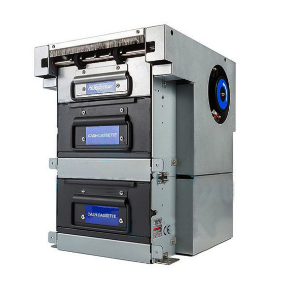
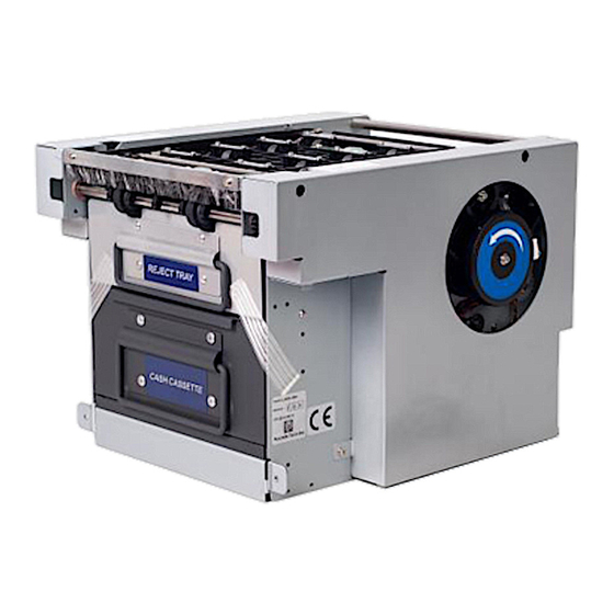
LCDM-2000 MAIN CONTROLLER CASH OUT REJECT TRAY CASH CASSETTE(Upper) CASH CASSETTE(Lower) DOUBLE FEEDING AUTO CASH FEEDER DETECTION PULOON Technology Inc. -
Page 4
LCDM-2000 Term Specification ˚ ˚ PULOON Technology Inc. -
Page 5
LCDM-2000 Cassette Door Door Open Direction Insert Locker Cash Plate Cassette Handle Cash Plate Stopper Cash Plate Handle PULOON Technology Inc. -
Page 6
Stopper is automatically closed & opened by backing pushing plate and opening door respectively. 1-3-4. Cash Cassette Base When cash cassette is inserted, the part of transporting open automatically by the function of Cash cassette base which is located in the part of transporting part. PULOON Technology Inc. -
Page 7
Bill-End sign will displayed with stopping the unit. There is hole in the front of “Cash Cassette” and detection process is done by this hole. ( Please refer to the layout of sensor for location) PULOON Technology Inc. -
Page 8
Feed Module consists of auto cash feeder part , double feeding detection part , diverting mechanism part , cash delivery part and Feature is shown below. Feed motor Note Path (Delivery) Diverter Pick-up Roller(Upper) One-way Roller(Upper) Double Detect Roller (Upper) Pick-up Roller(Lower) One-way Roller(Lower) Double Detect Roller (Lower) PULOON Technology Inc. -
Page 9
LCDM-2000 < Auto Cash Feeder >- PULOON Technology Inc. -
Page 10
LCDM-2000 Description Function ’ ’ ’ ’ PULOON Technology Inc. -
Page 11
LCDM-2000 < Constitution of Thickness Recognition > PULOON Technology Inc. -
Page 12
LCDM-2000 Description Function ’ ’ ’ PULOON Technology Inc. -
Page 13
LCDM-2000 < Constitution of divergence part > PULOON Technology Inc. -
Page 14
LCDM-2000 Description Function ’ ’ ’ ’ ’ ’ PULOON Technology Inc. -
Page 15
LCDM-2000 1-4-4. Transportation part < Constitution of Transportation part > PULOON Technology Inc. -
Page 16
LCDM-2000 — Segment Name Name ’ ’ ’ ’ ’ ’ ’ ’ ’ ’ ’ ’ ’ ’ ’ ’ ’ ’ ’ ’ ’ PULOON Technology Inc. -
Page 17
Note Path (Delivery) (11)REJECT TRAY S/W (14) CASH BOX SENSOR 0 (9) NEAREND (12) RVDT SENSOR 0 SENSOR 0 (1)(2)CHK SENSOR 1/2 (15) CASH BOX SENSOR 1 (10) NEAREND (13)RVDT SENSOR 1 SENSOR 1 (3)(4)CHK SENSOR 3/4 PULOON Technology Inc. -
Page 18
LCDM-2000 SENSOR Name Function PULOON Technology Inc. -
Page 19
LCDM-2000 1-4-6. Power Transportation part • G1 T3 MOTOR CLUTCH CLUTCH PULOON Technology Inc. -
Page 20
LCDM-2000 Name Function PULOON Technology Inc. -
Page 21
LCDM-2000 No Load Load TYPE Voltage Current Speed Torque Current Speed FB-806 180mA±1 4800rpm± 1kgf- 2400mA±2 3500rpm ±200rpm 00mA 250rpm 00mA PULOON Technology Inc. -
Page 22
LCDM-2000 2. H/W Constitution SENSOR Circuit DIP SWITCH SEGEMENT CPU,ROM,RAM RVDT Circuit Solenoid,Clutch BLDC MOTOR RS232 Communication Circuit 24V 5V Conversion Circuit PULOON Technology Inc. -
Page 23
Upper Near End sensor ( Near End 0 ) Upper RVDT ( RVDT 0 ) Wheel sensor BLDC Motor Reject Tray limit switch Lower Clutch ( Clutch 1 ) Divert Solenoid Upper Clutch ( Clutch 0 ) POWER RS232 Communication PULOON Technology Inc. -
Page 24
STOP or low speed of MOTOR DIVERT_JAM_RUN Jam in the DIV SENSOR part EJECT_JAM_RUN TIMEOUT between DIV SENSOR and EJT SENSOR JAM_IN_CRI_LOWR Jam in the CHK SENSOR 3/4 part UPPER_CASH_BOX No Upper Cash Cassette UPPER_CASH_BOX No Lower Cash Cassette PULOON Technology Inc. -
Page 25
— Is all of bill out from CASH CASSETTE? — Re install of CASH CASSETTE after checking above Management — Check NEAREND SENSOR in case of lack of bill < Normal Insertion of Bills > < Wrong Insertion of Bills > PULOON Technology Inc. -
Page 26
— Is idle roller rotation in the GUIDE CASH FEED 2 ASS’Y normal? — Is fixing screw in GUIDE CASH FEED 1 / 2 / 3 ASS’Y normal? — Try again after checking above situation. Management — In case of Jam, Turn a handle shown below PULOON Technology Inc. -
Page 27
— Is idle roller rotation status in GUIDE CASH FEED 7 ASS’Y normal? — Try again after checking above situation. Management — Replace ASS’Y in case of roller rotation problem in GUIDE CASH FEED 7 ASS’Y. PULOON Technology Inc. -
Page 28
— In case of interference between SHAFT DIVERTER ASS’Y & SHAFT ASS’Y CASH FEED 3, Adjust location of SOLENOID Management PIN( Please refer to below picture) — Replace ASS’Y in case of idle roller rotation problem in GUIDE CASH FEED 7 ASS’Y. PULOON Technology Inc. -
Page 29
Note Path (Delivery) (11)REJECT TRAY S/W (14) CASH BOX SENSOR 0 (9) NEAREND (12) RVDT SENSOR 0 SENSOR 0 (1)(2)CHK SENSOR 1/2 (15) CASH BOX SENSOR 1 (10) NEAREND (13)RVDT SENSOR 1 SENSOR 1 (3)(4)CHK SENSOR 3/4 PULOON Technology Inc. -
Page 30
REJECT TRAY is not closed -Is the location of REJECT TRAY normal? Check Point — Is the location of CONNECTOR normal? — Insert REJECT TRAY to main body. Management — Connect J20 CONNECTOR in the MAIN PCB. PULOON Technology Inc. -
Page 31
LCDM-2000 CODE Detail Stop or low speed of MOTOR — Is any obstacle in Power Transportation part? Check Point — Is the location of CONNECTOR correct? -Try again after checking above situation. Management — Check J15 CONNECTOR. PULOON Technology Inc. -
Page 32
LCDM-2000 “ ” PULOON Technology Inc. -
Page 33
LCDM-2000 PULOON Technology Inc. -
Page 34
LCDM-2000 “ ” PULOON Technology Inc. -
Page 35
LCDM-2000 “ ” “ ” “ ” PULOON Technology Inc. -
Page 36
LCDM-2000 “ ” “ ” “ ” “ ” “ ” PULOON Technology Inc. -
Page 37
LCDM-2000 “ ” “ ” PULOON Technology Inc. -
Page 38
LCDM-2000 PULOON Technology Inc.
-
Contents
-
Table of Contents
-
Bookmarks
Quick Links
Service Manual
Service Manual
Model
: LCDM-2000
(Cash Dispensing Module)
Total Page
: 38 pages (including cover)
Date
Version :
PULOON Technology Inc.
:
2001. 12
V2.1
Summary of Contents for Puloon LCDM-2000
-
Page 1
Service Manual Service Manual Model : LCDM-2000 (Cash Dispensing Module) Total Page : 38 pages (including cover) Date 2001. 12 Version : V2.1 PULOON Technology Inc. -
Page 2
2-2. Main Board Connector Layout 3. Error Code & Handling Method 3-1. Error Code & the details 3-2. Handling method according to Error Code 4. Self Diagnostic Mode using PC 4-1. Program Loading 4-2. Setting Procedure 4-3. Program Usage PULOON Technology Inc. -
Page 3
LCDM-2000 MAIN CONTROLLER CASH OUT REJECT TRAY CASH CASSETTE(Upper) CASH CASSETTE(Lower) DOUBLE FEEDING AUTO CASH FEEDER DETECTION PULOON Technology Inc. -
Page 4
LCDM-2000 Term Specification ˚ ˚ PULOON Technology Inc. -
Page 5
LCDM-2000 Cassette Door Door Open Direction Insert Locker Cash Plate Cassette Handle Cash Plate Stopper Cash Plate Handle PULOON Technology Inc. -
Page 6
Stopper is automatically closed & opened by backing pushing plate and opening door respectively. 1-3-4. Cash Cassette Base When cash cassette is inserted, the part of transporting open automatically by the function of Cash cassette base which is located in the part of transporting part. PULOON Technology Inc. -
Page 7
Bill-End sign will displayed with stopping the unit. There is hole in the front of “Cash Cassette” and detection process is done by this hole. ( Please refer to the layout of sensor for location) PULOON Technology Inc. -
Page 8
Feed Module consists of auto cash feeder part , double feeding detection part , diverting mechanism part , cash delivery part and Feature is shown below. Feed motor Note Path (Delivery) Diverter Pick-up Roller(Upper) One-way Roller(Upper) Double Detect Roller (Upper) Pick-up Roller(Lower) One-way Roller(Lower) Double Detect Roller (Lower) PULOON Technology Inc. -
Page 9
LCDM-2000 < Auto Cash Feeder >- PULOON Technology Inc. -
Page 10
LCDM-2000 Description Function ’ ’ ’ ’ PULOON Technology Inc. -
Page 11
LCDM-2000 < Constitution of Thickness Recognition > PULOON Technology Inc. -
Page 12
LCDM-2000 Description Function ’ ’ ’ PULOON Technology Inc. -
Page 13
LCDM-2000 < Constitution of divergence part > PULOON Technology Inc. -
Page 14
LCDM-2000 Description Function ’ ’ ’ ’ ’ ’ PULOON Technology Inc. -
Page 15
LCDM-2000 1-4-4. Transportation part < Constitution of Transportation part > PULOON Technology Inc. -
Page 16
LCDM-2000 — Segment Name Name ’ ’ ’ ’ ’ ’ ’ ’ ’ ’ ’ ’ ’ ’ ’ ’ ’ ’ ’ ’ ’ PULOON Technology Inc. -
Page 17
Note Path (Delivery) (11)REJECT TRAY S/W (14) CASH BOX SENSOR 0 (9) NEAREND (12) RVDT SENSOR 0 SENSOR 0 (1)(2)CHK SENSOR 1/2 (15) CASH BOX SENSOR 1 (10) NEAREND (13)RVDT SENSOR 1 SENSOR 1 (3)(4)CHK SENSOR 3/4 PULOON Technology Inc. -
Page 18
LCDM-2000 SENSOR Name Function PULOON Technology Inc. -
Page 19
LCDM-2000 1-4-6. Power Transportation part • G1 T3 MOTOR CLUTCH CLUTCH PULOON Technology Inc. -
Page 20
LCDM-2000 Name Function PULOON Technology Inc. -
Page 21
LCDM-2000 No Load Load TYPE Voltage Current Speed Torque Current Speed FB-806 180mA±1 4800rpm± 1kgf- 2400mA±2 3500rpm ±200rpm 00mA 250rpm 00mA PULOON Technology Inc. -
Page 22
LCDM-2000 2. H/W Constitution SENSOR Circuit DIP SWITCH SEGEMENT CPU,ROM,RAM RVDT Circuit Solenoid,Clutch BLDC MOTOR RS232 Communication Circuit 24V 5V Conversion Circuit PULOON Technology Inc. -
Page 23
Upper Near End sensor ( Near End 0 ) Upper RVDT ( RVDT 0 ) Wheel sensor BLDC Motor Reject Tray limit switch Lower Clutch ( Clutch 1 ) Divert Solenoid Upper Clutch ( Clutch 0 ) POWER RS232 Communication PULOON Technology Inc. -
Page 24
STOP or low speed of MOTOR DIVERT_JAM_RUN Jam in the DIV SENSOR part EJECT_JAM_RUN TIMEOUT between DIV SENSOR and EJT SENSOR JAM_IN_CRI_LOWR Jam in the CHK SENSOR 3/4 part UPPER_CASH_BOX No Upper Cash Cassette UPPER_CASH_BOX No Lower Cash Cassette PULOON Technology Inc. -
Page 25
— Is all of bill out from CASH CASSETTE? — Re install of CASH CASSETTE after checking above Management — Check NEAREND SENSOR in case of lack of bill < Normal Insertion of Bills > < Wrong Insertion of Bills > PULOON Technology Inc. -
Page 26
— Is idle roller rotation in the GUIDE CASH FEED 2 ASS’Y normal? — Is fixing screw in GUIDE CASH FEED 1 / 2 / 3 ASS’Y normal? — Try again after checking above situation. Management — In case of Jam, Turn a handle shown below PULOON Technology Inc. -
Page 27
— Is idle roller rotation status in GUIDE CASH FEED 7 ASS’Y normal? — Try again after checking above situation. Management — Replace ASS’Y in case of roller rotation problem in GUIDE CASH FEED 7 ASS’Y. PULOON Technology Inc. -
Page 28
— In case of interference between SHAFT DIVERTER ASS’Y & SHAFT ASS’Y CASH FEED 3, Adjust location of SOLENOID Management PIN( Please refer to below picture) — Replace ASS’Y in case of idle roller rotation problem in GUIDE CASH FEED 7 ASS’Y. PULOON Technology Inc. -
Page 29
Note Path (Delivery) (11)REJECT TRAY S/W (14) CASH BOX SENSOR 0 (9) NEAREND (12) RVDT SENSOR 0 SENSOR 0 (1)(2)CHK SENSOR 1/2 (15) CASH BOX SENSOR 1 (10) NEAREND (13)RVDT SENSOR 1 SENSOR 1 (3)(4)CHK SENSOR 3/4 PULOON Technology Inc. -
Page 30
REJECT TRAY is not closed -Is the location of REJECT TRAY normal? Check Point — Is the location of CONNECTOR normal? — Insert REJECT TRAY to main body. Management — Connect J20 CONNECTOR in the MAIN PCB. PULOON Technology Inc. -
Page 31
LCDM-2000 CODE Detail Stop or low speed of MOTOR — Is any obstacle in Power Transportation part? Check Point — Is the location of CONNECTOR correct? -Try again after checking above situation. Management — Check J15 CONNECTOR. PULOON Technology Inc. -
Page 32
LCDM-2000 “ ” PULOON Technology Inc. -
Page 33
LCDM-2000 PULOON Technology Inc. -
Page 34
LCDM-2000 “ ” PULOON Technology Inc. -
Page 35
LCDM-2000 “ ” “ ” “ ” PULOON Technology Inc. -
Page 36
LCDM-2000 “ ” “ ” “ ” “ ” “ ” PULOON Technology Inc. -
Page 37
LCDM-2000 “ ” “ ” PULOON Technology Inc. -
Page 38
LCDM-2000 PULOON Technology Inc.
- Manuals
- Brands
- Puloon Manuals
- Banknote Counter
- LCDM-1000
- Service manual
-
Contents
-
Table of Contents
-
Bookmarks
Quick Links
Service Manual
Service Manual
Model
: LCDM-1000
(Cash Dispensing Unit)
Total Page : 41 pages (including cover)
Date
Version :
PULOON Technology Inc.
:
Nov, 2004
V3.51(INT)
Related Manuals for Puloon LCDM-1000
Summary of Contents for Puloon LCDM-1000
-
Page 1
Service Manual Service Manual Model : LCDM-1000 (Cash Dispensing Unit) Total Page : 41 pages (including cover) Date Nov, 2004 Version : V3.51(INT) PULOON Technology Inc. -
Page 2
LCDM-1000 Revision Record Rev. No Date Description of Change Page V3.0(INT) 02.04.01 V3.5(INT) 04.09.01 V3.51(INT 04.11.01 PULOON Technology Inc. -
Page 3: Table Of Contents
1-3. Cash Cassette Structure 1-4. Feed Module Structure 2. H/W Constitution Layout 2-1. Main Board Parts 2-2. Main Board Connector Layout 3. Error Code & Recommended Actions 3-1. Error Code 3-2. Recommended Actions 4. Operating the LCDM-1000 PULOON Technology Inc.
-
Page 4: Functional Description
LCDM-1000 1. Functional Description 1-1. Introduction This Specification is related to LCDM-1000 which is applied to ATM for Retail Market & other Bill Exchanger. LCDM-1000 consists of Feed Module,Cash Cassette,Reject Tray & Main Controller.Features is below CASH OUT MAIN CONTROLLER…
-
Page 5: Specification
Standby Status : 160 mA , Rated Consuming Current Average current : 900 mA Operation Temperature 5 C ~ 40 C Storage Temperature -10 C ~ 60 C Operation Humidity 20% ~ 80% RH Storage Humidity 10% ~ 90% RH PULOON Technology Inc.
-
Page 6: Cash Cassette Structure
Cash cassette do the role of transporting inserted bill one by one to next module and consists of Cassette Door,Cassette Body & Cassette base Cassette Door Door Open Direction Insert Locker Cash Plate Cassette Handle Cash Plate Stopper Cash Plate Handle PULOON Technology Inc.
-
Page 7
Stopper is automatically closed & opened by backing pushing plate and opening door respectively. 1-3-4. Cash Cassette Base When cash cassette is inserted, the part of transporting open automatically by the function of Cash cassette base which is located in the part of transporting part. PULOON Technology Inc. -
Page 8
Bill-End sign will displayed with stopping the unit. There is hole in the front of “Cash Cassette” and detection process is done by this hole. ( Please refer to the layout of sensor for location) PULOON Technology Inc. -
Page 9: Feed Module Structure
Feed Module consists of auto cash feeder part , double feeding detection part , diverting mechanism part , cash delivery part and Feature is shown below. Feed motor Note Path (Delivery) Diverter Pick-up Roller One-way Roller Double Detect Roller PULOON Technology Inc.
-
Page 10
LCDM-1000 1-4-1. Auto Cash Feeder Part Reverse Roller Feed Roller Feed Gear Idle Roller 1 Idle Roller 2 < Auto Cash Feeder > PULOON Technology Inc. -
Page 11
Force transportation of (1) & (4) parts ROLLER IDLE Moving bills by spring force Separation & moving bills which was SHAFT FEED ROLLER ASS’Y picked up BEARING R-1030 Moving bills by spring force SHAFT ONEWAY ROLLER ASS’Y Separation of bills which was pick-up PULOON Technology Inc. -
Page 12
LCDM-1000 1-4-2. Double Feeding Detection Part < Constitution of Thickness Recognition > PULOON Technology Inc. -
Page 13
(7) SPRING RVDT TENSION Push power to DETECT ROLLER PLATE D/D SENSOR RVDT’ rotation STOPPER and transporting exact displacement using Elasticity LEVER D/D HINGE Transporting (4) rotation power with amplification using RVDT PULOON Technology Inc. -
Page 14
LCDM-1000 1-4-3. Diverting Mechanism Part < Constitution of divergence part > PULOON Technology Inc. -
Page 15
(normal location) according to SOLENOID’ movement Decision of EJECT & REJECT SHAFT DIVERTER ASS’Y (REJECT movement location) SHAFT ASS’Y CASH FEED 3 Bill moving ROLLER ROLLER ASS’Y IDLE 13 Bill moving ROLLER SOL SENSOR Checking the Diverter solenoid PULOON Technology Inc. -
Page 16
— This part consists of working ROLLER & subordinate ROLLER — Transportation GUIDE is MOLD GUIDE and embodiment of JAM FREE — Upper part can be easily separated for Maintenance (2) Constitution < Constitution of Transportation part > PULOON Technology Inc. -
Page 17
SHAFT ASS’Y CASH FEED 6 SHAFT ASS’Y CASH FEED 6 GUIDE CASH FEED 1 GUIDE CASH FEED 2 ASS’Y GUIDE CASH FEED 3 ASS’Y GUIDE CASH FEED 5 ASS’Y GUIDE CASH FEED 6 ASS’Y GUIDE CASH FEED 7 ASS’Y PULOON Technology Inc. -
Page 18
The number of Sensor is 12. The function & Layout is shown below. (1) Layout of SENSOR (12)SOL SENSOR (3)(4)DIV SENSOR 1 / 2 (6)EXIT SENSOR (5)EJT SENSOR (10)WHEEL SENSER Note Path (Delivery) (8)REJECT TRAY S/W (9)CASSETTE SENSOR (7)NEAREND SENSOR (1)(2)CHK SENSOR 1 / 2 (9)RVDT SENSOR PULOON Technology Inc. -
Page 19
REJECT TRAY S/W Checking the status of REJECT TRAY RVDT SENSOR Recognition of thickness of transported bill WHEEL SENSOR Control of transporting MOTOR speed (11) CASSETTE SENSOR Checking the CASH CASSETTE (12) SOL SENSOR Checking the Diverter solenoid PULOON Technology Inc. -
Page 20
LCDM-1000 1-4-5. Power Transportation part [1] Features • Transportation part work by single MOTOR and power for Bill separation part is transferred & controlled by CLUTCH [2] Constitution MOTOR CLUTCH PULOON Technology Inc. -
Page 21
(W=3.2) Reduction (3) MOTOR — MAKER : Fuji Micro — TYPE : Brushless DC Motor No Load Load TYPE Voltage Current Speed Torque Current Speed FB-806 DC 24V 180mA±1 4800rpm 1kgf-cm 2400mA± 3500rpm ±250rpm ±200rpm 00mA 200mA PULOON Technology Inc. -
Page 22: H/W Constitution
LCDM-1000 2. H/W Constitution 2-1. Layout of MAIN BOARD DIP SWITCH SENSOR Circuit CPU,ROM,RAM RVDT EEPROM Circuit Solenoid,Clutch BLDC MOTOR RS232 Communication 24V 5V Circuit Conversion Circuit PULOON Technology Inc.
-
Page 23
CHK1,DIV1 Sensor for accepting & emitting sensor EJT,EXIT emitting sensor Reject tray switch , Cassette Sensor,SOL sensor EJT,EXIT accepting Sensor CHK2,DIV2 accepting & emitting Sensor Diverter Solenoid Clutch RS232 Communication Power Brushless DC Motor Wheel Sensor RVDT Near-end Sensor PULOON Technology Inc. -
Page 24: Error Code & Recommended Actions
Timeout(From DIV Sensor to EJT Sensor) TABLE 3 Over Reject TABLE 7 Cassette is not recognized TABLE 8 Dispensing timeout TABLE 1 Diverter solenoid or SOL Sensor error TABLE 9 SOL Sensor TABLE 9 Purge error(JAM at DIV Sensor) TABLE 4 PULOON Technology Inc.
-
Page 25: Recommended Actions
— Is Bill inserted proper in the CASH CASSETTE ? Check Point — Is Push plate work smoothly in CASH CASSETTE? — Is any bill out from CASH CASSETTE? Action — Re install CASH CASSETTE after checking above < Normal loading > < Abnormal loading > PULOON Technology Inc.
-
Page 26
— Is idle roller rotation in the GUIDE CASH FEED 2 ASS’Y normal? — Is fixing screw in GUIDE CASH FEED 1 / 2 / 3 ASS’Y normal? — Try again after checking above situation. Action — In case of Jam, Turn a knob shown below PULOON Technology Inc. -
Page 27: Table 3
Point — Is idle roller rotation status in GUIDE CASH FEED 7 ASS’Y normal? — Try again after checking above situation. Action — Replace ASS’Y in case of roller rotation problem in GUIDE CASH FEED 7 ASS’Y. PULOON Technology Inc.
-
Page 28: Table 4
SHAFT ASS’Y CASH FEED 3, Adjust location of SOLENOID Action PIN( Please refer to below picture) — Replace ASS’Y in case of idle roller rotation problem in GUIDE CASH FEED 7 ASS’Y. Solenoid and Solenoid pin should be adjusted in arrow direction PULOON Technology Inc.
-
Page 29: Table 5
REJECT TRAY is not recognized -Is the location of REJECT TRAY normal? Check Point -Is the location of J18 CONNECTOR normal? — Insert REJECT TRAY to main body. Action — Connect J18 CONNECTOR in the MAIN PCB. PULOON Technology Inc.
-
Page 30: Table 6
— Is any obstacle in Power Transportation part? Check — Is the location of J3 CONNECTOR correct? Point — Is the location of J2 CONNECTOR correct? -Try again after checking above situation. Action — Check J3 CONNECTOR. — Check J2 CONNECTOR PULOON Technology Inc.
-
Page 31: Table 7
The length measured on check sensors is not out of limit. 9C 9F The banknote passed on check sensors is considered as too 9C 9D much skewed. 9C 03 The banknote are not normally passing on the check sensor because of fast consequential pickup. 9C 00 PULOON Technology Inc.
-
Page 32: Table 7
OFF: 0.13 ~ 0.15 (ex. CAD) <Display of Reject code > ON : Non-Display OFF: Display < Definition of Bill-End (option) > ON : 10~30 remain OFF: No bill remains !! Please turn on power again after changing the Dip Switch !! PULOON Technology Inc.
-
Page 33: Table 7
: It is rare case but sometimes the sensor or shaft error in production causes such a over-reject. It should be very serious and difficult to fix that in customer’s house. It is recommended the RVDT should be replaced with new one. PULOON Technology Inc.
-
Page 34
In case of piece cut from the bad banknote or improper material on the path, it enables to cause the skew amplification, which can occur over-reject. The note be changed with new one or the path should be cleared by dispensing the thick note size paper. PULOON Technology Inc. -
Page 35: Cassette Is Not Recognized
TABLE 8 CODE Meaning Cassette is not recognized — Is Cassette fully inserted to main body? Check Point — Is the location of J18 CONNECTOR correct? -Try again after checking above situation. Action — Check J18 CONNECTOR PULOON Technology Inc.
-
Page 36: Table 9
— SOL Sensor error — Is the location of J18 CONNECTOR correct? Check Point — Is the location of J9 CONNECTOR correct? -Try again after checking above situation. Action — Check J18 CONNECTOR. — Check J9 CONNECTOR PULOON Technology Inc.
-
Page 37: Table 10
LCDM-1000 TABLE 10 CODE Meaning — Bill-End Check — Is enough notes in the CASH CASSETTE? Point Action — Loading notes in the CASH CASSETTE PULOON Technology Inc.
-
Page 38: Table 11
LCDM-1000 TABLE 11 CODE Meaning -Note request error Check — Is requested dispensing notes of one transaction correct? Point — Dispensing notes of one transaction is from 1 note to 20 Action notes PULOON Technology Inc.
-
Page 39: Operating The Lcdm-1000
LCDM-1000 4. Operating the LCDM-1000 I. SETUP 1) Start the test program “LCDMTP” 2) Maintain default value like below. (If you need to choose another port, check the other port number) 3) Press “OK” button < Fig 1 : SETUP PAGE >…
-
Page 40
LCDM-1000 MENU Choose LCDM-1000 or LCDM-2000 < Fig 2 : MENU PAGE > PULOON Technology Inc. -
Page 41
(2) Fill in the blank of “Upper Request Count” and “Repeat Count” (Recommended Values are from 1~20 for the XXX Request Count, and 1~999 for the Repeat Count) (3) Press the button of “DISPENSE” <Fig 3 : Ten bills are dispensed 1time from cassette> PULOON Technology Inc. -
Page 42
LCDM-1000 (4) If Near-End occurs, V mark is checked at “Upper Empty” <Fig 4 : Near-End occurs> PULOON Technology Inc. -
Page 43
LCDM-1000 PURGE If you want to clear the note in the path, press the button of “Purge” <Fig 4 : Purge> PULOON Technology Inc. -
Page 44
LCDM-1000 III. STATUS Press “STATUS” button and all sensors are rechecked. This shows system status for you. If sensor error occurs, V mark is checked at each column accordingly. < Fig 5 : STATUS PAGE > PULOON Technology Inc. -
Page 45
Motor Speed, Bill Length, Test Dispense, Diverting, RVDT Value, ROM Version and Clutch Tests can be performed and examined. 3) The recommended values are shown in the Fig. 7 of next page. < Fig 6 : TP PAGE > PULOON Technology Inc. -
Page 46: Puloon Technology Inc
Higher than 0500 Double Lower than 0500 BILL LEN RVDT Normal Higher than 0430 Sensor (Thickness Double Lower than 0430 Normal Higher than 04C0 Double Lower than 04C0 CLUTCH Clutch Operation Test On/Off DIVERT Solenoid Operation Test On/Off PULOON Technology Inc.