1. Function
This LCD colour TV set incorporates a Lamp error detection feature that automatically turns off the power for safety under abnormal lamp or lamp
circuit conditions. If by any chance anything is wrong with the lamp or lamp circuit or if the lamp error detection feature is activated for some rea-
son, the following will result.
1) The power is interrupted in about 500ms after it is turned on.
(A central icon on the front of the TV flash on and off.: ON for 400ms and OFF for 1600ms.).
2) If the above phenomenon 1) occurs 5 times, it becomes impossible to turn on the power.
(A central icon keep flashing on/off.)
2. Measures
1) Set the lamp error detection to OFF
Enter the adjustment process mode, referring to «4. Entering and exiting the adjustment process mode.»
The adjustment process mode can ignore «5 times count», so If the above phenomenon 1) occurs 1~4 times, the lamp will go out.
If Lamp Error detection pin (6pin of LB: P9602) is «High» by a trouble with the lamp and lamp circuit, it can boot-up by the adjustment process
mode.
Please execute «Lamp Error detection off-mode».
While holding down the «VOL (-)» and «CH (
After a central icon flash off, separate the fingers from key on the set.
Touch the power supply key on the set again, so the power will boot-up.
Then, you can check the operation to see if the lamp and lamp circuit are in trouble.
If you fail boot-up, retry the procedure.
2) Resetting the lamp error count
After the lamp and lamp circuit are improved from a trouble, reset the lamp error count.
(Because the power cannot be turned on, if a lamp error is detected 5 consecutive times)
a) Enter the adjustment process mode, referring to «4. Entering and exiting the adjustment process mode.»
b) Using the cursor ( / ) key, move to the cursor to [LAMP ERROR RESET], Line 8 on adjustment process mode service page 2/21.
c) With the cursor ( / ) keys, select the [LAMP ERROR RESET] value.
Finally press the cursor (OK)., the count is reset.
Check LAMP ERROR Count on adjustment process mode Page 2/21.
Table of contents of adjustment process mode Page 2/21
INDUSTRY INIT
INDUSTRY INIT (-Publicl)
Public MODE
Center Acutime
RESET
Backlight Acutime
RESET
LAMP ERROR RESET
ADJ PARAM SET
VIC XPOS
VIC YPOS
VIC SIGNAL TYPE
VIC READ
)» keys on the set at once, touch the power supply key on the set.
Enter
OFF
OFF
OFF
OFF
Resetting to «0»
OFF
Enter
0
0
MAIN
OFF
5 – 8
LC-40/46LE810E (1st Edition)
Техническое описание и состав телевизора SHARP LC-40LE810E, тип панели и применяемые модули. Состав модулей.
Общие рекомендации по ремонту TV LCD LCD
Ремонт телевизора SHARP LC-40LE810E LC-40LE810ERU следует начинать с диагностики неисправности, которая предполагает внимательный осмотр внешних и внутренних элементов устройства.
В некоторых случаях видимые внешние повреждения элементов могут подсказать направления поиска неисправности и локализации дефекта ещё до начала проведения необходимых измерений в контрольных точках узлов электронных схем.
В некоторых случаях неисправные элементы видно невооружённым глазом, например, обугленные резисторы или вздувшиеся металлокерамические конденсаторы, либо электролитические в фильтрах выпрямителей. Образовавшиеся кольцевые трещины в пайках выводов трансформаторов или греющихся элементов схемы так же являются частыми источниками многих неисправностей с самыми различными внешними проявлениями.
Если телевизор не включается, не горят и не мигают никакие контрольные лампочки, нет никаких звуков при включении, ни малейших признаков работоспособности — наиболее вероятна неисправность в модуле питания.
При диагностике и ремонте блока питания, в первую очередь следует заменить вспухшие конденсаторы фильтра вторичных выпрямителей и проверить предохранитель и, если он оборван, необходимо выявить причину. Часто в таких случаях обнаруживается лавинный (тепловой) пробой в силовых полупроводниковых элементах модуля — диодах выпрямителя и транзисторах в первичной цепи.
В большинстве случаев, пробои ключей в импульсных источниках питания (ИИП) не происходит без причин и следует искать другие неисправные элементы схемы, которые могли спровоцировать дефект. Этом могут быть и высохшие электролитические конденсаторы в первичной цепи, и неисправные элементы демпфера, а также оборванные резисторы или пробитые полупроводниковые элементы в цепях стабилизации. Возможен брак микросхемы ШИМ от производителя.
Если у SHARP LC-40LE810E нет изображения, звук есть и каналы переключаются, есть вероятность неисправности ламп подсветки дисплея, либо преобразователя их питания — инвертора. Иногда при включении изображение появляется и сразу пропадает. В таких случаях необходимо проверить электролитические конденсаторы фильтра питания самого инвертора, в том числе и во вторичном выпрямителе основного БП.
Неообходимо учитывать, что в случаях отключения защиты инвертора (в целях возможности диагностики) есть риск выхода из строя силовых элементов инвертора и проявлять особую осторожность. После проведения ремонтных работ, цепи защиты необходимо обязательно восстановить для дальнейшей безопасной эксплуатации телевизора.
Диагностика и ремонт материнской платы QPWBXF455WJZZ // F455WE03 v1.10 обычно начинается с проверки работоспособности стабилизаторов и преобразователей питания чипов модуля. В некоторых случаях требуется обновление программного обеспечения (ПО).
В некоторых случаях требуют проверки или замены (если это необходимо) элементы платы MainBoard — CPU: R5F364A6NFB, M16C; NAND Flash: K9F1208UOC; . В случаях использования процессора BGA его неисправность обычно выявляется методом локального прогрева.
Если телевизор нормально работает от внешних устройств, но не настраивается на телевизионные каналы, возможна неисправность тюнера RTUDAA053WJQZ. В таких случаях в первую очередь следует убедиться в наличии напряжений питания на соответствующих его выводах. Иногда причиной неработоспособности тюнера может быть программный сбой.
Необходимо помнить пользователям, что попытки самостоятельного ремонта телевизора SHARP LC-40LE810E без соответствующей квалификации и необходимого опыта, могут привести к серьёзным негативным последствиям!
Дополнительно по ремонту MainBoard
Внешний вид MainBoard QPWBXF455WJZZ показан на рисунке ниже:
QPWBXF455WJZZ может применяться в телевизорах:
SHARP LC-40LE814E (Panel LK400D3LWF2Y), SHARP LC-40LE810E LC-40LE810ERU (Panel LK400D3LWF2Y).
Дополнительно по PSU
В телевизоре LC-40LE810E установлен модуль питания DPS-126CP с применением схемы PFC (Power Factor Correction) выполняющего функцию активного фильтра для устранения высших гармонических составляющих потребляемого тока. Повышающий преобразователь на основе ШИМ-регулятора NCP1608BDR2G не допускает подключение электролитического конденсатора фильтра входного выпрямителя к сети непосредственно через открытые диоды, когда величину тока заряда определяет его реактивное сопротивление (порядка 15-30 ом на частоте 50 гц.). В результате преобразования, зарядный ток конденсатора будет определяться таким образом, что огибающая высокочастотных импульсов входного тока повторит фазу и форму синусоиды входного напряжения. Проверка исправности узла PFC осуществляется замером постоянного напряжения на конденсаторе выпрямителя сети. В рабочем режиме должно быть около 380V, в дежурном примерно 300V.
Внешний вид блока питания
Основные особенности устройства SHARP LC-40LE810E:
Установлена матрица (LCD-панель) LK400D3LWF2Y.
Для питания ламп подсветки применён преобразователь, совмещённый с блоком питания, управляется ШИМ-контроллером DDA003A, DDA002B. В качестве силовых элементов инвертора применяются ключи типа 2N7002LT1G.
Формирование необходимых питающих напряжений для всех узлов телевизора SHARP LC-40LE810E осуществляет модуль питания DPS-126CP, либо его аналоги c использованием микросхем NCP1608BDR2G (PFC), ICE3BS03LJG (PWM 8pin), DDA002C и силовых ключей типа SPA11N60C3 (PFC), 2SK4013, FQPF10N60C.
MainBoard — основная плата (материнская плата) представляет собой модуль QPWBXF455WJZZ, с применением микросхем CPU: R5F364A6NFB, M16C; NAND Flash: K9F1208UOC; и других.
Тюнер RTUDAA053WJQZ обеспечивает приём телевизионных программ и настройку на каналы.
Внимание мастерам!
Информация на этом сайте накапливается из записей ремонтников и участников форумов.
Будьте внимательны! Возможны опечатки или ошибки!
Пожалуйста, сообщайте нам о любых ляпах или несоответствиях в записях по почте info@tel-spb.ru, присылайте прошивки и наработки из своего опыта, опубликуем в помощь коллегам.
Ближайшие в таблице модели:
SHARP LC-40LE814E
Panel: LK400D3LWF2Y
T-CON: RUNTKCPWBX 4512TP
LED driver (backlight): integrated into PSU
PWM LED driver: DDA003A, DDA002B
MOSFET LED driver: 2N7002LT1G
Power Supply (PSU): DPS-126CP
PWM Power: NCP1608BDR2G (PFC), ICE3BS03LJG (PWM 8pin), DDA002C
MOSFET Power: SPA11N60C3 (PFC), 2SK4013, FQPF10N60C
MainBoard: QPWBXF455WJZZ DKEYDF455FM11
Тuner: RTUDAA053WJQZ
IC Main: Mediatek MT5391DWCJ
SHARP LC-40LE730RU
Chassis(Version) DUNTKF915WE
Panel: LK400D3LB43 R1LK400D3LB43C
LED driver (backlight): integrated into PSU
PWM LED driver: MAP3222
MOSFET LED driver: 72T02GH
Power Supply (PSU): FSP148-3FS01
PWM Power: FAN7930C, STR-A6069H, SSC9522S
MainBoard: QPWBXF915WJN2 DUNTKF915WE17
Тuner: TDSV-G081D
IC Main: ZR39691HGCG (RH-IXD425WJZZQ), ZR39301BGCG (RH-IXD378WJZZQ), H5P5162GFR, K4B2G1646C-HCH9, 29F1G08ABADA, 25X20BVNIG, STA333BW (STA3338W)
54
Технические характеристики
Опция
Цветной телевизор с
жидкокристаллическим
дисплеем (40 o/81,28
см), LC-40LE820E,
LC-40LU820E, LC-
40LE810E, LC-40LX810E
Цветной телевизор с
жидкокристаллическим
дисплеем (46 o/116,84
см), LC-46LE820E,
LC-46LU820E, LC-
46LE810E, LC-46LX810E
Цветной телевизор с
жидкокристаллическим
дисплеем (52 o/132,08
см), LC-52LE820E
Панель жидкокристаллического дисплея
Advanced Super View
& BLACK TFT LCD (40
o
/81,28 см)
Advanced Super View
& BLACK TFT LCD (46
o
/116,84 см)
Advanced Super View
& BLACK TFT LCD (52
o
/132,08 см)
Разрешение
1 920 x 1 080 x 4 пикселов
Цветовая система видеосигнала
PAL/SECAM/NTSC 3,58/NTSC 4,43/PAL 60
ТВ функции
ТВ-Стандарт
Аналоговая
CCIR (B/G, I, D/K, L/L’)
Цифровая
DVB-T (2K/8K OFDM), DVB-C
Принимаемые
каналы
VHF/UHF
Каналы IR A_E69 (цифровые), E2_E69, F2_F10, I21_I69, IR A_IR J
CATV
Гипердиапазонные, каналы S1_S41
Система телевизионной настройки
Автоматическая предварительная установка: 999 каналов (все страны, за исключением
Северной Европы [DTV]), 9999 каналов (страны Северной Европы [DTV]), 99 каналов
(ATV), автоматическая маркировка, автоматическая сортировка
СТЕРЕО/ДВУЯЗЫЧНАЯ
NICAM/A2
Усилитель звука
10 Вт x 2/15 Вт x 1
Громкоговоритель
(234 мм x 22 мм) x 2/Ø 110 мм
Гнезда
Антенна
UHF/VHF 75 q Тип Din (Аналоговый и Цифровой)
RS-232C
9-штырьковый штекер D-Sub
EXT 1
SCART (Вход AV, вход Y/C, вход RGB, выход ТВ)
EXT 2
Разъем RCA (AV ввод/AUDIO L/R)
EXT 3
15-штырьковый мини D-sub
HDMI 1 (EXT 4)
HDMI (ARC)
HDMI 2 (EXT 5)
HDMI
HDMI 3 (EXT 6)
HDMI
HDMI 4 (EXT 7)
HDMI
USB
USB
ETHERNET (10/100)
Разъем для подключения к домашней сети (только в моделях серии 820)
HDMI 2/EXT 3 AUDIO (L/R)
Гнездо Ø 3,5 мм*
1
DIGITAL AUDIO OUTPUT
Оптический разъем S/PDIF для Цифровой аудиовыход
C. I. (Общий интерфейс)
EN50221, R206001, спецификации CI Плюс
OUTPUT/Наушники
Разъем RCA (AUDIO R/L)/штекер Ø 3,5 мм (аудиовыход)
Язык OSD
Чешский, датский, голландский, английский, эстонский, финский, французский,
немецкий, греческий, венгерский, итальянский, латвийский, литовский, норвежский,
польский, португальский, русский, словацкий, словенский, испанский, шведский,
турецкий, украинский
Требования к пиaтанию
220_240 В переменного тока, 50 Гц
Потребляемая мощность (Метод
IEC62087)
Модели 820
127 Вт (0,2 Вт в режиме
ожидания*
2
)
147 Вт (0,2 Вт в режиме
ожидания*
2
)
159 Вт (0,2 Вт в режиме
ожидания*
2
)
Модели 810
127 Вт (0,2 Вт в режиме
ожидания*
2
)
147 Вт (0,2 Вт в режиме
ожидания*
2
)
Вес
Модели 820
19,5 кг (Без подставки), 23,5
кг (С подставкой)
24,5 кг (Без подставки), 30,0
кг (С подставкой)
30,0 кг (Без подставки), 35,0
кг (С подставкой)
Модели 810
16,0 кг (Без подставки), 19,5
кг (С подставкой)
20,5 кг (Без подставки), 26,0
кг (С подставкой)
Рабочая температура
0 °C до e 40 °C
С обоими гнездами HDMI 2 и EXT 3 можно использовать одно и то же входное звуковое гнездо.
Указана мощность, потребляемая в режиме ожидания, когда телевизор не настроен на прием данных EPG.
В связи с постоянным совершенствованием продукции, фирма SHARP оставляет за собой право внесения изменений в дизайн и технические
характеристики без предварительного уведомления. Указанные технические характеристики являются номинальными значениями выпускаемых
аппаратов. Характеристики отдельных аппаратов могут несколько отличаться от этих величин.
I
J
•
Приложение
При использовании любой техники время от времени могут возникать неполадки. Так, например, при использовании копиров, принтеров и МФУ Sharpмогут появляться различные ошибки, вызванные различными причинами. Об их возникновении пользователь информируется с помощью кода, которые выводится на дисплее принтера или другого используемого устройства. Коды ошибок Sharp вы можете идентифицировать с помощью приведенной ниже таблицы. Выяснив причину сбоя в работе устройства, вы сможете устранить ее самостоятельно (например, если произошло замятие бумаги, отсутствует бумага в лотке) либо обратиться в сервисный центр по обслуживанию и ремонту Sharp, если код ошибки сообщает о серьезной поломке.
Sharp AL-840
| Код ошибки | Подкод | Описание |
|---|---|---|
| L1 | 00 | Неисправность при движении сканирующего устройства |
| L3 | 00 | Неисправность сканирующего устройства при возвращении в начальное положение |
| Е7 | 03 | Неисправность, связанная с яркостью свечения лазера |
| 04 | Ошибка при определении уровня белого при выполнении штриховки | |
| 05 | Ошибка при определении уровня черного при выполнении штриховки | |
| 12 | Ошибка уровня выходного сигнала при выполнении штриховки | |
| 14 | Сбой ASIC (MCU PWB) | |
| 15 | Неисправность копировальной лампы | |
| H2 | 00 | Неисправность термодатчика |
| H3 | 00 | Температура вала узла закрепления превысила норму |
| H4 | 00 | Температура вала узла закрепления опустилась ниже положенного уровня |
| U2 | 01 | Неисправность EEPROM (MCU PWB) (ошибка данных счетчика) |
| 04 | Неисправность EEPROM (MCU PWB) (ошибка записи/чтения) | |
| 05 | Неисправность EEPROM (MCU PWB) | |
| 06 | Неисправность ROM (MCU PWB) | |
| C1 | Неисправность, обнаруженная выключателем передней панели (блока питания) | |
| CH | Отсутствует тонер-картридж | |
| E1 | Замятие бумаги при подаче из лотка | |
| E2 | Замятие бумаги | |
| E3 | Замятие бумаги на выходе узла закрепления | |
| P | Отсутствие бумаги в лотке |
Sharp AL-1000
| Код ошибки | Подкод | Описание |
|---|---|---|
| E7 | 03 | Неисправность блока лазера, связанная с излучающим диодом и его цепями |
| 04 | Ошибка при определении уровня белого при выполнении штриховки | |
| 05 | Ошибка при определении уровня черного при выполнении штриховки | |
| 12 | Ошибка уровня выходного сигнала при выполнении штриховки | |
| 14 | Сбой ASIC (MCU PWB) | |
| 15 | Неисправность копировальной лампы | |
| L1 | 00 | Неисправность при движении сканирующего устройства (датчик начального положения сканирующего устройства не видит движения зеркал) |
| L3 | 00 | Неисправность сканирующего устройства при возвращении в начальное положение (сканер не успел вернутся в начальное положение за определенное время) |
| L4 | 01 | Main motor drive overloaded |
| L6 | 10 | Неисправность двигателя многогранника блока лазера (полигон-мотор) |
| H2 | 00 | Неисправность термодатчика |
| H3 | 00 | Температура вала узла закрепления превысила норму |
| H4 | 00 | Температура вала узла закрепления опустилась ниже положенного уровня |
| U2 | 01 | Неисправность EEPROM (MCU PWB) (ошибка данных счетчика) |
| 04 | Неисправность EEPROM (MCU PWB) (ошибка записи/чтения) | |
| CH | Отсутствует тонер-картридж |
Sharp AL-1010
| Код ошибки | Подкод | Описание |
|---|---|---|
| E7 | 03 | Scanner position error |
| 04 | Exposure lamp blown | |
| 05 | CCD calibration error | |
| 12 | White level calibration error | |
| 14 | Main board malfunction | |
| 15 | Exposure lamp blown | |
| L1 | 00 | Scanner position error |
| L3 | 00 | Scanner position error |
| L4 | 01 | Main motor drive overloaded |
| L6 | 10 | Polygon mirror motor not up to speed |
| H2 | 00 | Fusing unit temperature error |
| H3 | 00 | Overheated fusing unit |
| H4 | 00 | The fusing unit doesn’t heat up |
| U2 | 01 | Counter error |
| 04 | EPROM error | |
| CH blinking | Dev unit is not properly installed |
Sharp AR-160 / 161
| Код ошибки | Подкод | Описание |
|---|---|---|
| CC | Original not detected | |
| E1 | 00 | Lost communication with the Sorter |
| 10 | Lost communication with the Sorter | |
| 11 | ASIC error | |
| 12 | Image Processing Unit error | |
| 13 | ROM error | |
| 14 | NVRAM error | |
| 15 | Page memory fault | |
| 16 | SIMM not present or installed incorectly | |
| 17 | Page rotation error in RAM | |
| 80 | Electronic sort board error | |
| 81 | ||
| 82 | ||
| 84 | ||
| 88 | ||
| E7 | 03 | Lens position error |
| 04 | White level calibration error | |
| 05 | Black level calibration error | |
| 12 | CCD calibration error | |
| F1 | 06 | Shift sort motor overloaded |
| F5 | 02 | Exposure lamp blown |
| F6 | 00 | Fax board problems |
| 10 | ||
| 80 | ||
| 81 | ||
| 82 | ||
| 84 | ||
| 88 | ||
| F9 | 00 | Printer board problems |
| 10 | ||
| 80 | ||
| 81 | ||
| 82 | ||
| 84 | ||
| 88 | ||
| H2 | 00 | Fusing unit temperature error |
| H3 | 00 | Overheated fusing unit |
| H4 | 00 | The fusing unit doesn’t heat up |
| L1 | 00 | Scanner position error |
| L3 | 00 | Scanner position error |
| L4 | 01 | Main motor drive overloaded |
| 10 | Separation motor overloaded | |
| L6 | 10 | Polygon mirror motor not up to speed |
| L8 | 01 | Zero cross signal error |
| U2 | 04 | EPROM error |
| 11 | Main counter error | |
| 12 | EPROM error | |
| U3 | 29 | Mirror position error |
| U9 | 00 | Op panel problem |
| 81 | ||
| 82 | ||
| 84 | ||
| 88 | ||
| U95 | Firmware error |
Sharp AR-163 / 201 / 206 / 5015 / 5020
| Код ошибки | Подкод | Описание |
|---|---|---|
| E1 | 00 | Неисправность связи с платой электронного сортировщика |
| 10 | Неисправность платы электронного сортировщика | |
| 11 | Ошибка ASIC электронного сортировщика | |
| 12 | Ошибка CODEC электронного сортировщика | |
| 13 | Ошибка очистки (сброса) ROM электронного сортировщика | |
| 14 | Ошибка RAM электронного сортировщика | |
| 15 | Ошибка сохранения страницы в памяти электронного сортировщика | |
| 16 | Ошибка SIMM электронного сортировщика | |
| 17 | Ошибка RAM | |
| 80 | Неисправность связи с платой электронного сортировщика (PROTOCOL) | |
| 81 | Неисправность связи с платой электронного сортировщика (PARITY) | |
| 82 | Неисправность связи с платой электронного сортировщика (OVERRUN) | |
| 84 | Неисправность связи с платой электронного сортировщика (FRAMING) | |
| 88 | Неисправность связи с платой электронного сортировщика (TIME-OUT) | |
| E7 | 03 | Неисправность блока лазера |
| 04 | Ошибка определения уровня белого CCD | |
| 05 | Ошибка при определении уровня черного CCD | |
| F1 | 06 | Неисправность Shifter (двигателя сдвига копии) |
| F2 | 04 | Ошибка чтения данных CRUM (чипа тонер-картриджа) |
| F5 | 02 | Неисправность копировальной лампы |
| F6 | 00 | Ошибка связи с платой факса |
| 10 | Неисправность платы факса | |
| 80 | Ошибка связи с платой факса (PROTOCOL) | |
| 81 | Ошибка связи с платой факса (PARITY) | |
| 82 | Ошибка связи с платой факса (OVERRUN) | |
| 84 | Ошибка связи с платой факса (FRAMING) | |
| 88 | Ошибка связи с платой факса (TIME-OUT) | |
| F9 | 00 | Ошибка связи с платой принтера |
| 10 | Неисправность платы принтера | |
| 80 | Ошибка связи с платой принтера (PROTOCOL) | |
| 81 | Ошибка связи с платой принтера (PARITY) | |
| 82 | Ошибка связи с платой принтера (OVERRUN) | |
| 84 | Ошибка связи с платой принтера (FRAMING) | |
| 88 | Ошибка связи с платой принтера (TIME-OUT) | |
| H2 | 00 | Неисправность термодатчика |
| H3 | 00 | Температура вала узла закрепления превысила норму |
| H4 | 00 | Температура вала узла закрепления опустилась ниже положенного уровня |
| L1 | 00 | Обнаружена неисправность при определении начального положения сканирующей каретки |
| L3 | 00 | Обнаружена неисправность при обратном ходе сканирующей каретки |
| L4 | 01 | Неисправность главного двигателя |
| 10 | Неисправность двигателя сепаратора | |
| L6 | 10 | Неисправность двигателя многогранника блока лазера (полигон-мотор) |
| L8 | 01 | Ошибка сигнала пересечения нуля |
| U2 | 04 | EEPROM serial communication error |
| 11 | counter check sum error | |
| 12 | adjustment value check sum error(EEPROM) | |
| 40 | CRUM communication error | |
| U3 | 29 | Ошибка в определении начального положения зеркал |
| U9 | 00 | Ошибка связи с панелью управления (PROTOCOL) |
| 80 | Ошибка связи с панелью управления (PARITY) | |
| 82 | Ошибка связи с панелью управления (OVERRUN) | |
| 84 | Ошибка связи с панелью управления (FRAMING) | |
| 88 | Ошибка связи с панелью управления (TIME-OUT) | |
| U95 | Неисправность соединения платы управления | |
| U99 |
Sharp AR-405
| Код ошибки | Подкод | Описание |
|---|---|---|
| C1 | 00 | MC unit malfunction |
| C2 | 00 | TC unit malfunction |
| E7 | 00 | Image Processing Unit error |
| 01 | Memory back-up battery dead | |
| 02 | Laser unit problem | |
| 03 | HDD defective | |
| 10 | black level calibration error | |
| 11 | white level calibration error | |
| 13 | CCD calibration error | |
| 90 | Image Processing Unit error | |
| F1 | 00 | Lost communication with the Sorter |
| 01 | Sorter registration problem | |
| 02 | Paper transport motor overloaded in sorter | |
| 04 | Bin position error in sorter | |
| 05 | Bin position error in sorter | |
| 06 | Shift sort motor overloaded | |
| 08 | Stapler position error | |
| 08 | Stapler overloaded | |
| 11 | Sorter problems | |
| 14 | Second shift tray jammed | |
| 15 | Sorter drive problems | |
| 50 | Sorter not installed properly | |
| 80 | No powerin sorter | |
| F2 | 00 | ID pattern reading error |
| 02 | Toner add mechanism malfunction | |
| 31 | ID pattern reading error | |
| 32 | ID pattern reading error | |
| 39 | Drum thermistor error | |
| F3 | 12 | Paper does not lift in the tray |
| 22 | Paper does not lift in the tray | |
| F9 | 00 | Printer board problems |
| 01 | Printer board problems | |
| 02 | Printer board problems | |
| 03 | Network card error | |
| 04 | Firmware error | |
| 05 | Not enough memory | |
| 10 | Printer board problems | |
| 90 | Printer board problems | |
| H2 | 00 | Fusing unit temperature error |
| 01 | Fusing unit temperature error | |
| H3 | 00 | Overheated fusing unit |
| 01 | Overheated fusing unit | |
| H4 | 00 | The fusing unit doesn’t heat up |
| 01 | The fusing unit doesn’t heat up | |
| H5 | 01 | Papersensordefective in the fusing unit |
| 02 | Fusing unit temperature error | |
| L1 | 00 | Scanner position error |
| L3 | 00 | Scanner position error |
| L4 | 01 | Main motor drive overloaded |
| L6 | 10 | Polygon mirror motor not up to speed |
| L8 | 01 | Zero cross signal error |
| 02 | Zero cross signal error | |
| U2 | 00 | EPROM error |
| 11 | EPROM error | |
| U4 | 02 | Duplex not working properly |
| 03 | Duplex problems | |
| U5 | 00 | Communication with the ADF is lost |
| 01 | Registration sensor problem in ADF | |
| 02 | Exit sensor error in ADF | |
| 03 | Timing sensor problems in ADF | |
| 11 | Paper feed drive overloaded in ADF | |
| U6 | 01 | Paper lift problem in 1’st optional tray |
| 02 | Paper lift problem in 2’nd optional tray | |
| 08 | Paper feed unit without power | |
| 10 | PFU paper transport motor overloaded | |
| 22 | Paper feed unit without power | |
| 50 | Paper feed unit not installed properly | |
| 51 | LCT not installed properly | |
| U7 | 00 | Main board malfunction |
| U9 | 00 | Op panel problem |
| 90 | Op panel problem | |
| EE | EU | Low toner density in the developer |
| EE | EL | High toner density in the developer |
| FA | 01 | Memory back-up battery dead |
| PC | Key counter not installed |

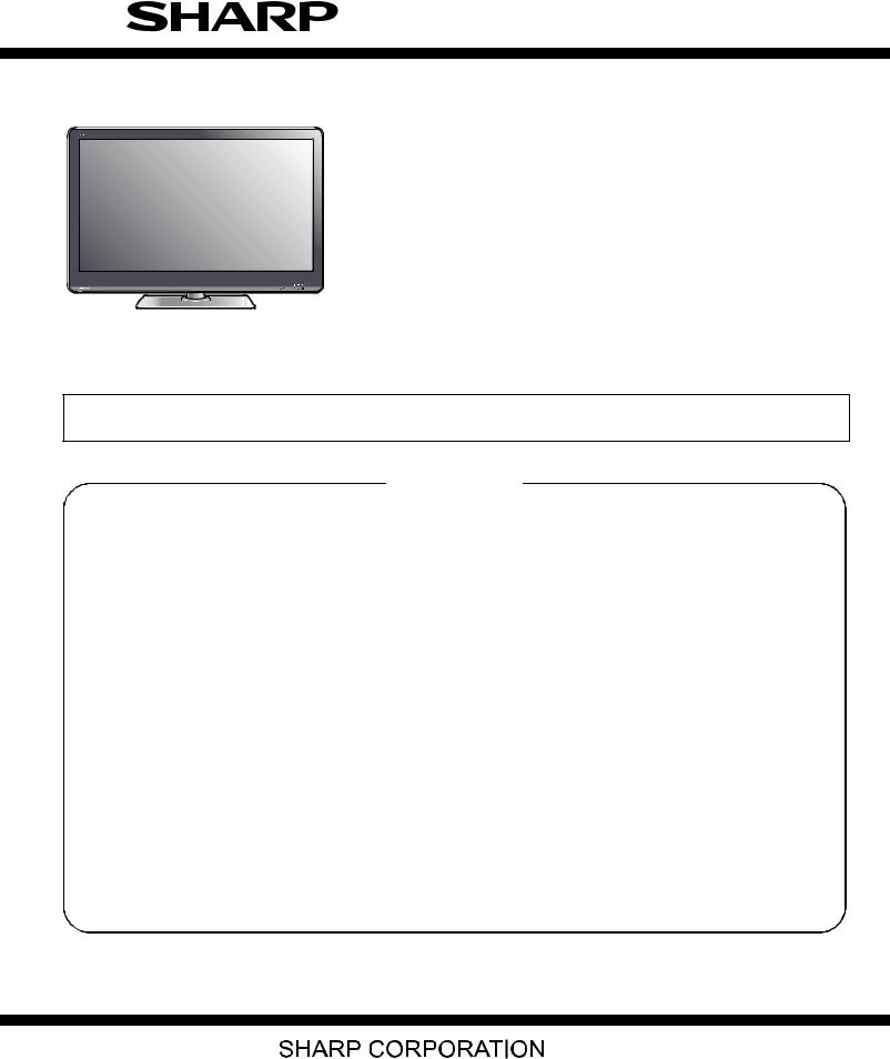
LC-40/46LE810E, LC-40/46LX810E
SERVICE MANUAL
No. S30E940LE810E
LCD COLOUR TELEVISION
LC-40LE810E
LC-46LE810E
LC-40LX810E
MODELS LC-46LX810E
In the interests of user-safety (Required by safety regulations in some countries) the set should be restored to its original condition and only parts identical to those specified should be used.
CONTENTS
|
SAFETY PRECAUTION |
CHAPTER 5. ADJUSTMENT |
||||
|
IMPORTANT SERVICE SAFETY PRE- |
[1] |
ADJUSTMENT PROCEDURE …………………. |
5-1 |
||
|
CAUTION ………………………………………………….. |
i |
CHAPTER 6. TROUBLESHOOTING TABLE |
|||
|
Precautions for using lead-free solder ………….. |
ii |
||||
|
End of life disposal ……………………………………. |
iii |
[1] |
TROUBLESHOOTING TABLE …………………. |
6-1 |
|
|
[2] LED flashing specification at the time of the |
|||||
|
OUTLINE |
error ……………………………………………………. |
6-13 |
|||
|
MAJOR SERVICE PARTS …………………………. |
iv |
CHAPTER 7. MAJOR IC INFORMATIONS |
|||
|
CHAPTER 1. SPECIFICATIONS |
[1] |
MAJOR IC INFORMATIONS ……………………. |
7-1 |
||
|
[1] |
SPECIFICATIONS …………………………………. |
1-1 |
CHAPTER 8. OVERALL WIRING/BLOCK DIAGRAM |
||
|
CHAPTER 2. OPERATION MANUAL |
[1] |
OVERALL WIRING DIAGRAM |
|||
|
[1] |
OPERATION MANUAL …………………………… |
2-1 |
(LC-40LE810E/LX810E)………………………….. |
8-1 |
|
|
[2] |
OVERALL WIRING DIAGRAM |
||||
|
CHAPTER 3. DIMENSIONS |
(LC-46LE810E/LX810E)………………………….. |
8-2 |
|||
|
[1] |
DIMENSIONS (LC-40LE810E/LX810E).……. |
3-1 |
[3] |
SYSTEM BLOCK DIAGRAM……………………. |
8-3 |
|
[2] |
DIMENSIONS (LC-46LE810E/LX810E).……. |
3-2 |
Parts Guide |
||
CHAPTER 4. REMOVING OF MAJOR PARTS
[1]REMOVING OF MAJOR PARTS
|
(LC-40LE810E/LX810E) …………………………. |
4-1 |
[2]REMOVING OF MAJOR PARTS
|
(LC-46LE810E/LX810E) …………………………. |
4-6 |
Parts marked with » 
This document has been published to be used for after sales service only.
The contents are subject to change without notice.
LC-40/46LE810E, LC-40/46LX810E
SAFETY PRECAUTION
IMPORTANT SERVICE SAFETY PRECAUTION
Service work should be performed only by qualified service technicians who are thoroughly familiar with all safety checks and the servicing guidelines which follow:
WARNING
1.For continued safety, no modification of any circuit should be attempted.
2.Disconnect AC power before servicing.
CAUTION:
FOR CONTINUED PROTECTION AGAINST A RISK OF FIRE REPLACE ONLY WITH SAME TYPE FUSE.
40 inch model: F7000, F7001 (3.15A/250V)
46 inch model: F7000, F7001 (5A/250V)
BEFORE RETURNING THE RECEIVER
(Fire & Shock Hazard)
Before returning the receiver to the user, perform the following safety checks:
3.Inspect all lead dress to make certain that leads are not pinched, and check that hardware is not lodged between the chassis and other metal parts in the receiver.
4.Inspect all protective devices such as non-metallic control knobs, insulation materials, cabinet backs, adjustment and compartment covers or shields, isolation resistor-capacitor networks, mechanical insulators, etc.
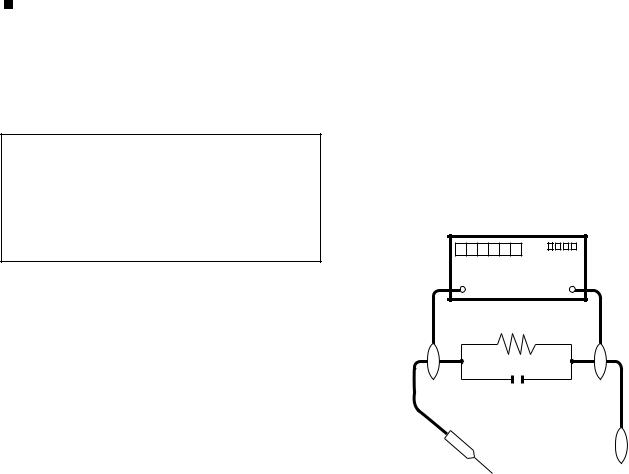
5.To be sure that no shock hazard exists, check for leakage current in the following manner.
•Use an AC voltmeter having with 5000 ohm per volt, or higher, sensitivity or measure the AC voltage drop across the resistor.
•Connect the resistor connection to all exposed metal parts having a return to the chassis (antenna, metal cabinet, screw heads, knobs and control shafts, escutcheon, etc.) and measure the AC voltage drop across the resistor.
All checks must be repeated with the AC cord plug connection reversed. (If necessary, a nonpolarized adaptor plug must be used only for the purpose of completing these checks.)
Any reading of 1.05 V peak (this corresponds to 0.7 mA peak AC.) or more is excessive and indicates a potential shock hazard which must be corrected before returning the monitor to the owner.
DVM
AC SCALE
1.5k ohm
10W
0.15 µF
TEST PROBE
•Plug the AC cord directly into a 220~240 volt AC outlet.
•Using two clip leads, connect a 1.5k ohm, 10 watt resistor paralleled by a 0.15µF capacitor in series with all exposed metal cabinet parts and a known earth ground, such as electrical conduit or electrical ground connected to an earth ground.
|
TO EXPOSED |
CONNECT TO |
|
METAL PARTS |
KNOWN EARTH |
|
GROUND |
///////////////////////////////////////////////////////////////////////////////////////////////////////////////////////////////////////////////////////////////////////////////////////////////////////////////////////////////////////////
SAFETY NOTICE
Many electrical and mechanical parts in LCD color television have special safety-related characteristics.
These characteristics are often not evident from visual inspection, nor can protection afforded by them be necessarily increased by using replacement components rated for higher voltage, wattage, etc.
Replacement parts which have these special safety characteristics are identified in this manual; electrical components having such features
are identified by “
For continued protection, replacement parts must be identical to those used in the original circuit.
The use of a substitute replacement parts which do not have the same safety characteristics as the factory recommended replacement parts shown in this service manual, may create shock, fire or other hazards.
///////////////////////////////////////////////////////////////////////////////////////////////////////////////////////////////////////////////////////////////////////////////////////////////////////////////////////////////////////////
i
LC-40/46LE810E, LC-40/46LX810E
Precautions for using lead-free solder
Employing lead-free solder
•“PWBs” of this model employs lead-free solder. The LF symbol indicates lead-free solder, and is attached on the PWBs and service manuals. The alphabetical character following LF shows the type of lead-free solder.
Example:
|
L |
F |
a |
L |
F |
a/a |
||||
Indicates lead-free solder of tin, silver and copper.
Indicates lead-free solder of tin, silver and copper.
Using lead-free wire solder
•When fixing the PWB soldered with the lead-free solder, apply lead-free wire solder. Repairing with conventional lead wire solder may cause damage or accident due to cracks.
As the melting point of lead-free solder (Sn-Ag-Cu) is higher than the lead wire solder by 40 °C, we recommend you to use a dedicated soldering bit, if you are not familiar with how to obtain lead-free wire solder or soldering bit, contact our service station or service branch in your area.
Soldering
•As the melting point of lead-free solder (Sn-Ag-Cu) is about 220 °C which is higher than the conventional lead solder by 40 °C, and as it has poor solder wettability, you may be apt to keep the soldering bit in contact with the PWB for extended period of time. However, Since the land may be peeled off or the maximum heat-resistance temperature of parts may be exceeded, remove the bit from the PWB as soon as you confirm the steady soldering condition.
Lead-free solder contains more tin, and the end of the soldering bit may be easily corroded. Make sure to turn on and off the power of the bit as required.
If a different type of solder stays on the tip of the soldering bit, it is alloyed with lead-free solder. Clean the bit after every use of it. When the tip of the soldering bit is blackened during use, file it with steel wool or fine sandpaper.
•Be careful when replacing parts with polarity indication on the PWB silk.
Lead-free wire solder for servicing
|
Part No. |
Description |
Code |
|||
|
ZHNDAi123250E |
J |
φ0.3mm 250g |
(1roll) |
BL |
|
|
ZHNDAi126500E |
J |
φ0.6mm |
500g |
(1roll) |
BK |
|
ZHNDAi12801KE |
J |
φ1.0mm |
1kg (1roll) |
BM |
ii
LC-40/46LE810E, LC-40/46LX810E
End of life disposal
End of life disposal
iii
LC-40/46LE810E, LC-40/46LX810E
OUTLINE
MAJOR SERVICE PARTS
PWB UNIT
|
Ref No. |
Parts Code |
Description |
|
N |
DKEYDF455FM03 |
MAIN Unit (*1) |
|
N |
DUNTKF494FM02 |
R/C, LED Unit |
|
N |
DUNTKF493FM03 |
ICON Unit |
|
N |
RUNTKA692WJQZ |
TOUCH SENSOR Unit (*2) |
|
N |
RUNTKA685WJQZ |
POWER Unit (LC-40LE810E/LX810E) |
|
N |
RUNTKA686WJQZ |
POWER Unit (LC-46LE810E/LX810E) |
|
N |
RUNTK4512TPZC |
LCD CONTROL Unit (LC-40LE810E/LX810E) |
|
N |
RUNTK4437TPZE |
LCD CONTROL Unit (LC-46LE810E/LX810E) |
|
N |
RUNTK4462TPZZ |
LED PWB Unit, x4 (LC-40LE810E/LX810E) |
|
N |
RUNTK4461TPZZ |
LED PWB Unit, x4 (LC-46LE810E/LX810E) |
NOTE: (*1) Replace MAIN Unit (DKEYDF455FM03) in case of IC8401 or IC3302 failure.
(*2) TOUCH SENSOR Unit (RUNTKA692WJQZ) reuse will be impossible, once it is stuck on front cabinet and exfoliates. Therefore, please exchange of a TOUCH SENSOR Unit in the case of front cabinet exchange.
OTHER UNIT
|
Ref No. |
Parts Code |
Description |
|
|
N |
R1LK400D3LWF2Y |
40” LCD Panel Module Unit (LC-40LE810E/LX810E) |
|
|
N |
R1LK460D3LWA2Y |
46” LCD Panel Module Unit (LC-46LE810E/LX810E) |
|
|
IC FOR EXCLUSIVE USE OF THE SERVICE |
|||
|
Ref No. |
Parts Code |
Description |
Q’ty |
|
IC501 |
RH-iXD108WJQZS |
IC 24LC21AT-I/SN |
1 |
|
IC2002 |
RH-iXC786WJNJQ |
IC R5F364A6NFB |
1 |
|
SERVICE JIGS |
|||
|
Ref No. |
Parts Code |
Description |
Q’ty |
|
N |
QCNW-G616WJQZ |
Main Unit to LCD Control Unit (LW) |
1 |
|
N |
QCNW-G625WJQZ |
Main Unit to Power Unit (PL) |
1 |
|
N |
QCNW-H184WJQZ |
Main Unit to Power Unit (PD) |
1 |
|
N |
QCNW-H185WJQZ |
Main Unit to Power (LED Drive) Unit (LB) |
1 |
|
N |
QCNW-K594WJQZ |
Main Unit to R/C, LED Unit (RA) |
1 |
|
N |
QCNW-K595WJQZ |
Main Unit to Speaker (SP) |
1 |
|
N |
QCNW-K597WJQZ |
Main Unit to Woofer (SB) |
1 |
iv

LC-40/46LE810E, LC-40/46LX810E
CHAPTER 1. SPECIFICATIONS
[1] SPECIFICATIONS
|
Item |
LCD COLOUR TV (40«/81.28 cm), |
LCD COLOUR TV (46«/116.84 cm), |
||
|
LC-40LE810E/LC-40LX810E |
LC-46LE810E/LC-46LX810E |
|||
|
LCD panel |
Advanced Super View & BLACK TFT |
Advanced Super View & BLACK TFT |
||
|
LCD (40«/81.28 cm) |
LCD (46″/116.84 cm) |
|||
|
Resolution |
1,920 x 1,080 x 4 pixels |
|||
|
Video colour system |
PAL/SECAM/NTSC 3.58/NTSC 4.43/PAL 60 |
|||
|
TV function |
TV-standard |
Analogue |
CCIR (B/G, I, D/K, L/L’) |
|
|
Digital |
DVB-T (2K/8K OFDM), DVB-C |
|||
|
Receiving |
VHF/UHF |
IR A ch-E69 ch (Digital), E2-E69 ch, F2-F10 ch, I21-I69 ch, IR A-IR J ch |
||
|
channel |
||||
|
CATV |
Hyper-band, S1-S41 ch |
|||
|
TV-tuning system |
Auto Preset 999 ch (non-Nordic [DTV]), Auto Preset 9999 ch (Nordic [DTV]), |
|||
|
Auto Preset 99 ch (ATV), Auto Label, Auto Sort |
||||
|
STEREO/BILINGUAL |
NICAM/A2 |
|||
|
Audio amplifier |
10 W x 2/15 W x 1 |
|||
|
Speaker |
(234 mm x 22 mm) x 2/Ø 110 mm |
|||
|
Terminals |
Antenna |
UHF/VHF 75 Din type (analogue & digital) |
||
|
RS-232C |
D-Sub 9 pin male connector |
|||
|
EXT 1 |
SCART (AV input, Y/C input, RGB input, TV output) |
|||
|
EXT 2 |
RCA pin (AV input/AUDIO L/R) |
|||
|
EXT 3 |
15 pin mini D-sub |
|||
|
HDMI 1 (EXT 4) |
HDMI (ARC) |
|||
|
HDMI 2 (EXT 5) |
HDMI |
|||
|
HDMI 3 (EXT 6) |
HDMI |
|||
|
HDMI 4 (EXT 7) |
HDMI |
|||
|
USB |
USB |
|||
|
ETHERNET (10/100) |
Home network connector (only the 820 model series) |
|||
|
HDMI 2/EXT 3 AUDIO (L/R) |
Ø 3.5 mm jack*1 |
|||
|
DIGITAL AUDIO OUTPUT |
Optical S/PDIF digital audio output |
|||
|
C. I. (Common Interface) |
EN50221, R206001, CI Plus specification |
|||
|
OUTPUT/Headphones |
RCA pin (AUDIO R/L)/Ø 3.5 mm jack (audio output) |
|||
|
OSD language |
Czech, Danish, Dutch, English, Estonian, Finnish, French, German, Greek, |
|||
|
Hungarian, Italian, Latvian, Lithuanian, Norwegian, Polish, Portuguese, Russian, |
||||
|
Slovak, Slovene, Spanish, Swedish, Turkish, Ukrainian |
||||
|
Power requirement |
AC 220 — 240 V, 50 Hz |
|||
|
Power consumption (method IEC62087) |
127 W (0.2 W standby*2) |
147 W (0.2 W standby*2) |
||
|
Weight |
16.0 kg (without stand), |
20.5 kg (without stand), |
||
|
19.5 kg (with stand) |
26.0 kg (with stand) |
|||
|
Operating temperature |
0 °C to + 40 °C |
|||
*1 The HDMI 2 and EXT 3 terminals can both use the same audio input terminal.
*2 Standby power consumption applies when the TV is set to not receive EPG data.
•As a part of our policy of continuous improvement, SHARP reserves the right to make design and specification changes for product improvement without prior notice. The performance specification figures indicated are nominal values of production units. There may be some deviations from these values in individual units.
1 – 1
LC-40/46LE810E, LC-40/46LX810E
CHAPTER 2. OPERATION MANUAL
[1] OPERATION MANUAL
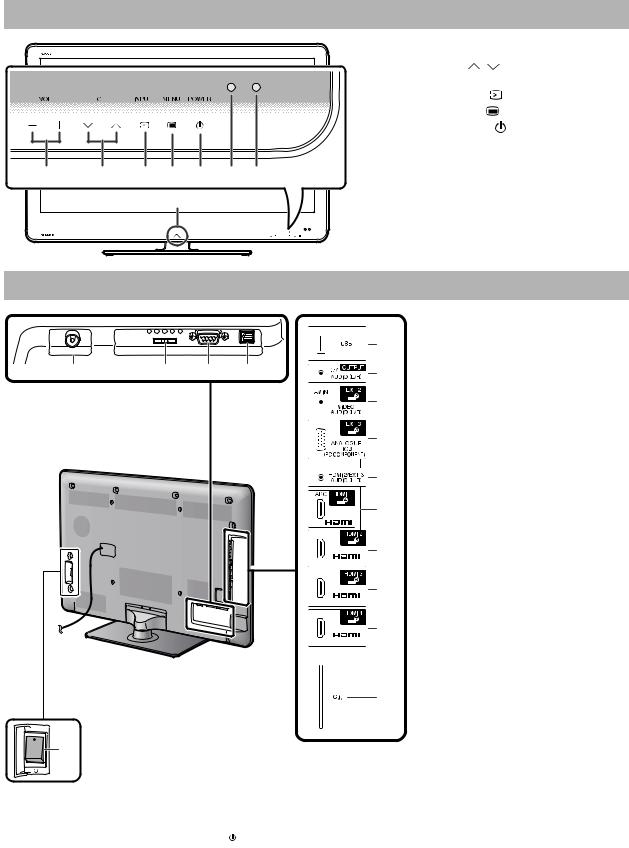
TV (front view)
|
1 |
VOL -/+ |
(Volume buttons) |
|||
|
2 |
CH / |
(Programme [channel] |
|||
|
buttons) |
|||||
|
3 |
INPUT |
(Input source button) |
|||
|
4 |
MANU |
(Menu button) |
|||
|
5 |
POWER |
(Power button) |
|||
|
6 |
OPC sensor |
||||
|
7 |
Remote control sensor |
||||
|
1 |
2 |
3 4 5 6 7 |
8 |
Illumination LED |
|
|
8 |
TV (rear view)
|
1 |
Antenna terminal |
|||||
|
5 |
2 |
EXT 1 (RGB) terminal |
||||
|
3 |
RS-232C terminal |
|||||
|
1 |
2 |
3 |
4 |
6 |
4 |
DIGITAL AUDIO OUTPUT |
|
terminal |
||||||
|
7 |
5 |
USB terminal |
||||
|
6 |
OUTPUT (Headphones/AUDIO |
|||||
|
8 |
(L/R)) terminal |
|||||
|
7 |
EXT 2 (AV IN/VIDEO/AUDIO (L/R)) |
|||||
|
*1 |
terminal |
|||||
|
9 |
8 |
EXT 3 (ANALOGUE RGB (PC/ |
||||
|
COMPONENT)) terminal |
||||||
|
10 |
9 |
HDMI 2/EXT 3 AUDIO (L/R) jack |
||||
|
10 |
HDMI 1 (HDMI/ARC) terminal |
|||||
|
11 |
11 |
HDMI 2 (HDMI) terminal |
||||
|
12 |
HDMI 3 (HDMI) terminal |
|||||
|
13 |
HDMI 4 (HDMI) terminal |
|||||
|
12 |
14 |
C.I. (COMMON INTERFACE) slot |
||||
|
15 |
MAIN POWER switch |
|
13 |
WARNING |
|
|
• Excessive sound pressure from earphones |
||
|
and headphones can cause hearing loss. |
||
|
• Do not set the volume at a high level. |
||
|
Hearing experts advise against extended |
||
|
listening at high volume levels. |
||
|
14 |
||
|
*2 |
||
|
15 |
*1 The HDMI 2 and EXT 3 terminals can both use the same audio input terminal (HDMI 2/EXT 3 AUDIO (L/R)). However, the proper item must be selected in the “Audio select” menu.
*2 When the MAIN POWER switch is turned off ( ), the amount of electric power consumed will be reduced to 0.01 W or less. However, unlike when unplugging the AC cord, the power is not completely disconnected.
2 – 1
LC-40/46LE810E, LC-40/46LX810E
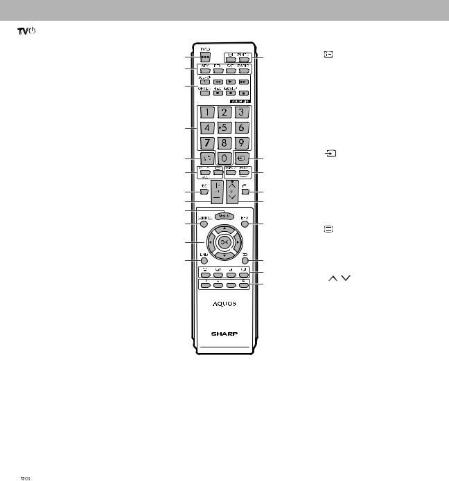
Remote control unit
|
1 |
(Standby/On) |
12 |
END |
||
|
Exit the “Menu” screen. |
|||||
|
2 |
ATV |
1 |
13 |
13 |
(Display information) |
|
Press to access conventional |
Press to display the station |
||||
|
2 |
|||||
|
analogue TV mode. |
information (channel number, signal, |
||||
|
DTV |
3 |
etc.) in the upper right corner of the |
|||
|
screen. |
|||||
|
Press to access digital TV mode. |
|||||
|
SAT |
P. INFO |
|||||
|
Press to display programme |
||||||
|
This function is not available. |
||||||
|
information transmitted through |
||||||
|
4 |
||||||
|
digital video broadcasting (DTV |
||||||
|
RADIO |
||||||
|
only). |
||||||
|
DTV: Switch between radio and |
||||||
|
14 |
(INPUT) |
|||||
|
data mode. |
5 |
14 |
||||
|
Select an input source. |
||||||
|
• When only data broadcasting |
||||||
|
6 |
15 |
|||||
|
(no radio broadcasting) is |
15 |
AV MODE |
||||
|
transmitted by DVB, the radio |
7 |
16 |
Select a video setting. |
|||
|
broadcasting will be skipped. |
ECO (Standard/Advanced/Off) |
|||||
|
8 |
17 |
|||||
|
3 |
AQUOS LINK buttons |
Select “Energy save” setting. |
||||
|
9 |
||||||
|
If external equipment such as a |
||||||
|
AQUOS BD player is connected via |
10 |
18 |
16 |
(Teletext) |
||
|
HDMI cables and is AQUOS LINK |
||||||
|
ATV: Display analogue teletext. |
||||||
|
compatible, you can use these |
11 |
|||||
|
DTV: Select MHEG-5 and teletext |
||||||
|
AQUOS LINK buttons. |
||||||
|
for DTV. |
||||||
|
12 |
19 |
|||||
|
20 |
17 |
P |
/ |
|||
|
21 |
||||||
|
Select the TV channel. |
||||||
4Numeric buttons 0_9
Set the channel.
Enter desired numbers.
Set the page in teletext mode.
•When the five Nordic countries (Sweden, Norway, Finland, Denmark or Iceland) are selected in the country setting from “Auto installation”, DTV services are four digits. When another country is selected, DTV services are three digits.
5
Press to return to the previously selected channel or external input.
6
Select a sound multiplex mode.

Select a wide mode.
7
TV sound on/off.
8
Increase/decrease TV volume.
9MENU
“Menu” screen on/off.
10CONTROL
Press to display the panel to operate some functions on the screen.
11


Select a desired item on the setting screen.
OK
Execute a command within the “Menu” screen.
ATV/DTV: Display “CH list” when no other “Menu” screen is running.
18EPG
DTV: Display the EPG screen.
19
Return to the previous “Menu” screen.
20Buttons for useful operations

Switch subtitle languages on/off .


Press to freeze a moving image on the screen.
Teletext: Stop updating teletext pages automatically or release the hold mode.
21R/G/Y/B (Colour) buttons
The coloured buttons are correspondingly used to select the coloured items on the screen (e.g., EPG, MHEG-5, teletext).
2 – 2
LC-40/46LE810E, LC-40/46LX810E
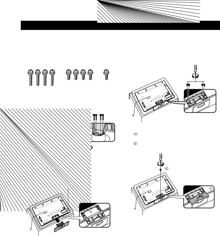
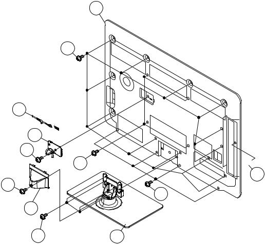
Attaching the stand unit
•Before performing work, spread cushioning over the surface on which you will be laying the TV. This will prevent it from being damaged.
CAUTION
•Attach the stand in the correct direction.
•Be sure to follow the instructions. Incorrect installation of the stand may result in the TV falling over.
1Confirm that there are nine screws (four long screws and five short screws) with the stand unit.
2Attach the supporting post for the stand unit onto the base using the four long screws with a screwdriver as shown.
Supporting
post
3Insert the stand into the openings on the bottom of the TV (hold the stand so it will not drop from the edge of the base area).
Soft cushion
4Insert and tighten four short screws into the four holes on the rear of the TV.
5Attaching the stand cover.
Slide the stand cover into the two catches on the stand base.
Insert and tighten a short screw into the hole on the centre of the stand cover.
NOTE
•To detach the stand unit, perform the steps in reverse order.
•A screwdriver is not supplied with this product.
•The stand base is made of glass. Therefore, be careful not to drop the stand base or apply pressure to it.
•Do not place heavy objects on the stand base.
2 – 3
LC-40/46LE810E, LC-40/46LX810E
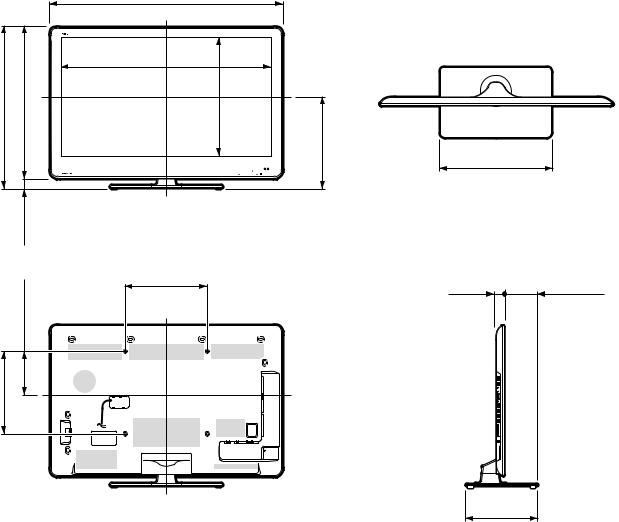
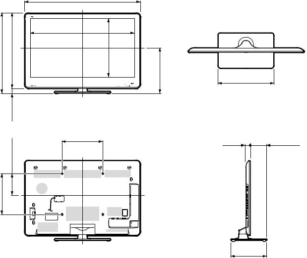
CHAPTER 3. DIMENSIONS
[1] DIMENSIONS (LC-40LE810E/LX810E)
|
992.0 |
|||||
|
992,0 |
|||||
|
887.8 |
|||||
|
706.0 |
706,0 |
658.0 |
658,0 |
887,8 |
|
|
500.4 |
500,4 |
|
48.0 |
48,0 |
||
|
132.0 |
132,0 |
300.0 |
|
|
300,0 |
|||
|
300.0 |
300,0 |
Unit: mm
450.0
450,0
39.5124.0
39,5 124,0
275.0
275,0
3 – 1
[2] DIMENSIONS (LC-46LE810E/LX810E)
1125.0
1125,0
|
1020.8 |
|||||||
|
784.0 |
784,0 |
733.0 |
733,0 |
1020,8 |
|||
|
575.4 |
575,4 |
444.0 |
444,0 |
||||
|
51.0 |
51,0 |
||||||
|
211.0 |
211,0 |
400.0 |
|||||
|
400,0 |
|||||||
|
400.0 |
400,0 |
LC-40/46LE810E, LC-40/46LX810E
Unit: mm
540.0
540,0
39.5157.1
39,5 157,1
340.0
340,0
3 – 2
LC-40/46LE810E, LC-40/46LX810E
CHAPTER 4. REMOVING OF MAJOR PARTS
[1] REMOVING OF MAJOR PARTS (LC-40LE810E/LX810E)
1. Removing of Stand Unit and Rear Cabinet Ass’y.
1.Remove the 1 lock screw 

2.Remove the 4 lock screw 

3.Remove the 1 lock screw 

4.Disconnect AC wire and detach the AC Cord 
5.Remove the 4 lock screw 


12 Rear Cabinet Ass’y
11
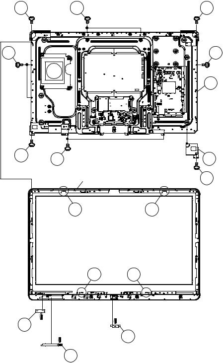
[AC]
AC Cord Cover 6
5
8 
1
10
Support Cover 2
4 – 1
LC-40/46LE810E, LC-40/46LX810E
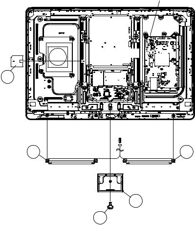
2. Removing of Speaker-L/R.
1.Remove the 1 lock screw 

2.Disconnect SP wire.
3.Detach the Speaker-L 

4.Detach the Insulation Sheet (AC) 
MAIN Unit
[SP]
5
Insulation
Sheet (AC)
[SP]
2 Stand Cover
1
4 – 2
LC-40/46LE810E, LC-40/46LX810E
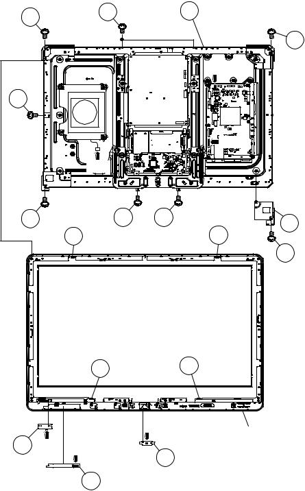
3. Removing of 40” LCD Panel Module Unit, TOUCH SENSOR Unit, ICON Unit, R/C, LED Unit, Front Cabinet Ass’y.
1.Disconnect RA, SB wire.
2.Detach the TOUCH SENSOR Unit 
3.Detach the ICON Unit 
4.Detach the R/C, LED Unit 
5.Remove the 1 lock screw 

6.Remove the 5 lock screws 


|
6 |
7 |
9 40″ LCD Panel Module Unit |
||
|
6 |
||||
|
[SB] |
||||
|
7 |
||||
|
[RA] |
||||
|
[SB] |
||||
|
6 |
6 |
6 |
5 |
LCD Angle |
|
8 |
8 |
(Bottom-R) |
||
|
4 |
8 8
|
3 [RA] [RK] |
2 ICON Unit |
|
|
R/C, LED Unit |
||
|
1 TOUCH SENSOR Unit |
4 – 3
LC-40/46LE810E, LC-40/46LX810E
4. Removing of Connectors
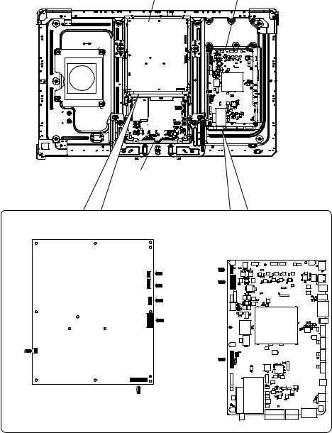
1.Disconnect the following connectors from the MAIN Unit. (LB, PD, LW)
2.Disconnect the following connectors from the POWER Unit. (L1, L2, LB, PD, PL, AS)
3.Disconnect the following connectors from the LCD CONTROL Unit. (LW, PL)
LCD CONTROL Unit
|
POWER Unit |
MAIN Unit |
|
[L1] |
[LB] |
|
[L2] |
[PD] |
|
[LB] |
|
|
[PD] |
|
|
[AS] |
[LW] |
|
[PL] |
4 – 4
LC-40/46LE810E, LC-40/46LX810E
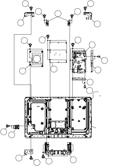
5. Removing of MAIN Unit, POWER Unit, Woofer, Stand Angle.
1.Remove the 7 lock screws 
2.Remove the 2 lock screws 

3.Remove the 2 lock screws 

4.Remove the 6 lock screws 

5.Remove the 4 lock screws 

6.Remove the 8 lock screws 

7.Remove the 1 lock screw 

8.Remove the 1 lock screw 

9.Remove the 1 lock screw 


11.Remove the 2 lock screws 

17
LCD Angle 18
(Top-L)
9
10 Woofer
21
22
ECO Switch
with Holder
LCD Angle 14 (Bottom-L)
|
VESA |
15 |
|
|
Angle |
||
|
11 |
12 |
11 |
16 LCD Angle
(Top-R)
1
2 MAIN Unit
5
6 Terminal Angle
(Side)
4 Terminal Angle
(Bottom)
3

40″ LCD Panel
Module Unit
20 Stand Angle
4 – 5
LC-40/46LE810E, LC-40/46LX810E
[2] REMOVING OF MAJOR PARTS (LC-46LE810E/LX810E)
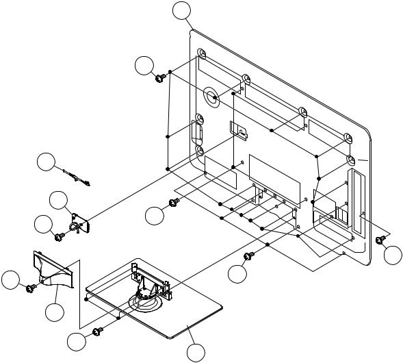
1. Removing of Stand Unit and Rear Cabinet Ass’y.
1.Remove the 1 lock screw 

2.Remove the 4 lock screws 

3.Remove the 1 lock screw 

4.Disconnect AC wire and detach the AC Cord 
5.Remove the 4 lock screws 


12 Rear Cabinet Ass’y
11
[AC]
AC Cord 7

AC Cord Cover 6
8
5
9
Support Cover 2
3
4 Stand Unit
4 – 6
LC-40/46LE810E, LC-40/46LX810E
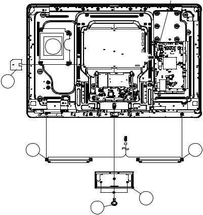
2. Removing of Speaker-L/R.
1.Remove the 3 lock screws 

2.Disconnect SP wire.
3.Detach the Speaker-L 

4.Detach the Insulation Sheet (AC) 
MAIN Unit
|
[SP] |
|
|
5 |
|
|
Insulation |
|
|
Sheet (AC) |
|
|
[SP] |
|
|
Speaker-R 4 |
3 Speaker-L |
|
2 |
Stand Cover |
|
1 |
4 – 7
LC-40/46LE810E, LC-40/46LX810E
3. Removing of 46” LCD Panel Module Unit, TOUCH SENSOR Unit, ICON Unit, R/C, LED Unit, Front Cabinet Ass’y.
1.Remove the 1 lock screw 

2.Remove the 5 lock screws 


3.Disconnect RA wire.
4.Detach the TOUCH SENSOR Unit 
5.Detach the ICON Unit 
6.Detach the R/C, LED Unit 
NOTE: The TOUCH SENSOR Unit removed once is not reusable.
|
4 |
4 |
|
|
6 |
||
|
46″ LCD Panel |
||
|
[RA] |
Module Unit |
|
|
3 |
3 |
2 LCD Angle |
|
(Bottom-R) |
||
|
Front Cabinet Ass’y |
1 |
|
|
5 |
5 |
55
|
[RI] |
||
|
9 [RA] |
||
|
R/C, LED Unit |
[RK] |
8 ICON Unit |
|
7 |
TOUCH SENSOR Unit |
4 – 8
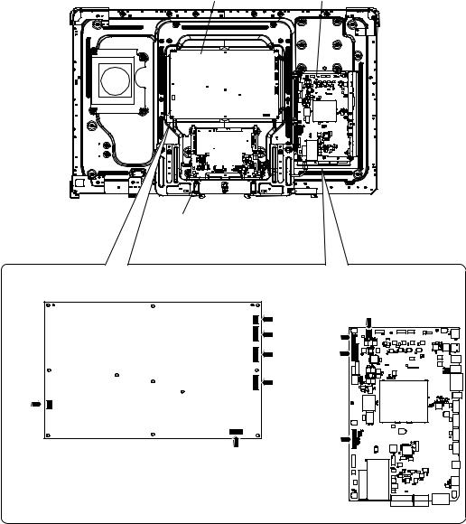
LC-40/46LE810E, LC-40/46LX810E
4. Removing of Connectors
1.Disconnect the following connectors from the MAIN Unit. (SB, LB, PD, LW)
2.Disconnect the following connectors from the POWER Unit. (L1, L2, LB, PD, PL, AS)
3.Disconnect the following connectors from the LCD CONTROL Unit. (LW, PL)
|
POWER Unit |
MAIN Unit |
|
[LW]
[PL]
LCD CONTROL Unit
|
POWER Unit |
MAIN Unit |
|
[L1] |
[SB] |
|
[L2] |
[LB] |
|
[LB] |
[PD] |
|
[PD] |
|
|
[AS] |
|
|
[LW] |
|
|
[PL] |
4 – 9
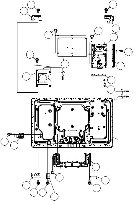
LC-40/46LE810E, LC-40/46LX810E
5. Removing of MAIN Unit, POWER Unit, Sub Woofer, Stand Angle.
1.Remove the 7 lock screws 
2.Remove the 2 lock screws 

3.Remove the 2 lock screws 

4.Remove the 6 lock screws 

5.Remove the 4 lock screws 

6.Remove the 1 lock screw 

7.Remove the 1 lock screw 

8.Remove the 1 lock screw 

9.Remove the 1 lock screw 


11.Remove the 8 lock screws 


LCD Angle 14
(Top-L)
|
1 |
12 LCD Angle (Top-R) |
||||
|
7 |
|||||
|
2 |
MAIN Unit |
||||
|
9 |
5 |
||||
|
8 POWER |
6 Terminal Angle |
||||
|
Unit |
|||||
|
(Side) |
|||||
|
10 |
|||||
|
4 |
Terminal Angle |
||||
|
Woofer |
[SB] |
||||
|
(Bottom) |
|||||
|
3 |
|||||
|
[L1] |
|||||
|
[L2] |
|
23 |
46″ LCD Panel |
|||
|
24 |
Module Unit |
|||
|
ECO Switch |
||||
|
with Holder |
||||
|
22 Stand Angle |
||||
|
21 |
20 LCD Angle (B-C-B) |
|||
|
LCD Angle 18 |
19 |
|||
|
(Bottom-L) |
17 |
15 |
||
16 LCD Angle (B-C-A)
4 – 10
LC-40/46LE810E, LC-40/46LX810E
CHAPTER 5. ADJUSTMENT
[1] ADJUSTMENT PROCEDURE
1. Adjustment method after PWB and/or IC replacement due to repair
The unit is set to the optimum at the time of shipment from the factory.
If any value should become improper or any adjustment is necessary due to the part replacement, make an adjustment according to the following procedure.
1.Procure the following units in order to replace the main unit MAIN UNIT: DKEYDF455FM03
NOTE: [Caution when replacing ICs in the main unit (IC501, IC2002)]
The above ICs are EEPROMs storing the EDID data of PC, and Monitor microcomputer.
Before replacing the relevant part, procure the following parts in which the data have been rewritten.
|
IC501 |
RH-iXD108WJQZS |
PC EDID |
|
IC2002 |
RH-iXC786WJNJQ |
Monitor microcomputer |
NOTE: [Caution when replacing ICs in the main unit (IC8401, IC3302)]
When replacing either IC8401 or IC3302, exchange MAIN units for DKEYDF455FM01
Each part should not be individually exchanged.
|
IC8401 |
RH-iXC147WJQZQ |
Flash |
|
IC3302 |
RH-iXC951WJN1Q |
Main CPU |
NOTE: HDMI ROM Writing
After replacing IC1504, execute “HDMI EDID WRITE” on the page 5/21
Please execute it after checking MODEL NAME & INCH SIZE. are correct.
IF MODEL NAME & INCH SIZE. are not correct, set them previously. (Refer to 2)
The ROM data based on information of MODEL NAME & INCH SIZE
1)Enter the process adjustment mode in TV.
2)Use the cursor keys (


2.After replacing the LCD panel or LCD control/MAIN UNIT, check MODEL NAME in the following procedure.
1)Enter the process adjustment mode in TV.
2)Use the cursor keys (


3)Verify that the Model name is displayed.
4)If the Model name doesn’t match, select the values of the Model name with the VOL keys (+/-).
5)After selection in Step 4), press the OK key, and it is completed with OK displayed.
6)Use the cursor keys (


7)Verify that the panel size is displayed.

9)After selection in Step 8), press the OK key, and it is completed with OK displayed.
3.After replacing the LCD panel or LCD control PWB, adjust the VCOM in the following procedure.
1)Enter the process adjustment mode.
2)Use the cursor keys (


3)Press the OK key to verify that the adjustment pattern is displayed.
4)Use VOL keys (+/-) of R/C to adjust the flicker in the center of the screen to minimum.
5)When the optimal state is achieved in Step 4, press the OK key to turn the pattern to OFF.
5 – 1

LC-40/46LE810E, LC-40/46LX810E
2. Method of shuts down for Power supply
Please execute the following procedures to shut down Power supply from the state of normal operation.
1)Keep touching the power supply key on the set for 5 seconds from the state of watching.
*The screen disappears when power supply key is touched, but Keep pushing the power supply key.
2)A central icon lights between 500ms when the power supply shuts down.
Please separate the finger from the power supply key when lighting of a central icon is confirmed
3. Entering and exiting the adjustment process mode
Please execute the following procedures to enter the adjustment process mode when the power supply shuts down.
1)While holding down the “VOL (-)” and “INPUT” keys on the set at once, touch the power supply key on the set. Please separate the fingers from key on the set when boot-up is confirmed with lighting of a central icon etc. After a while, The letter “K” appears on the screen. This state is in Inspection mode.
2)Next, hold down the “VOL (-)” and “CH (
Multiple lines of blue characters appearing on the screen indicate that the set is now in the adjustment Process mode. If you fail to enter the adjustment process mode (the display is the same as normal startup), retry the procedure.
3)To exit the adjustment process mode after the adjustment is done, unplug the AC power cord to force off the power.
(When the power is turned off with the remote controler, once unplug the AC power cord and plug it in again. In this case, wait for 10 seconds or so after unplugging.)
CAUTION: Use due care in handling the information described here lest the users should know how to enter the adjustment process mode. If the settings are tampered with in this mode, unrecoverable system damage may result.
4. Remote controler key operation and description of display in adjustment process mode.
1. Key operation
|
Remote controler key |
Main unit key |
Remote controler key Main unit key Function |
||
|
CH keys ( |
/ ) |
CH ( / ) |
Moving an item (line) by one (UP/DOWN) |
|
|
VOL keys (+/-) |
VOL (+/-) |
Changing a selected item setting (+1/-1) |
||
|
Cursor ( |
/ |
) |
— |
Turning a page (PREVIOUS/NEXT) |
|
Cursor ( |
/ |
) |
— |
Changing a selected line setting (+10/-10) |
|
INPUT |
INPUT |
Input source switching (toggle switching) (TV→EXT1~9, USB) |
||
|
OK |
— |
Executing a function |
||
|
RETURN |
— |
Returning to a present page |
Input mode is switched automatically when relevant adjustment is started so far as the necessary input signal is available.
5 – 2
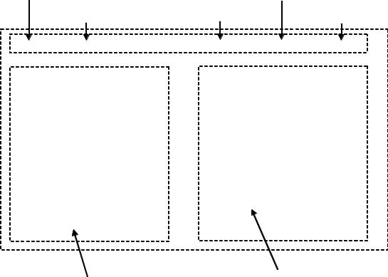
LC-40/46LE810E, LC-40/46LX810E
5. Description of display
|
(1) Present page / number of total pages |
(4) Inducing display |
|
(3) Present colour system |
|
|
(2) Input that has been selected now |
(5) Inch setting and Model name display |
1/21 INPUT1
MAIN Version
BOOT Version
Monitor Version
T-CON Version/LED CON Version
CPLD Version
CI+INFO/SECURE BOOT
FRC-N Auto Script Version
TCON Master/Slave Serial Version
TOUCH SENSOR UCON VERSION
LAMP ERROR
MONITOR ERR CAUSE
NORMAL STANDBY CAUSE ERROR STANDBY CAUSE
1.00 (E 2009/**/** ) xxxxxxx
xxxxxxx xxxxxxxx/xxxx xxxxxxx xxxxx/YES xxxxxxx xxxxxxx xxxxxxx
0
1)xxxxxx 2)xxxxxx 3)xxxxxx 4)xxxxxx 0 0 0 0 0
|
(6) Item name |
(7) Parameter |
|
|
No. |
Description |
Display specification |
|
(1) |
Present page/number of total pages |
2char/2char Decimal Number mark. |
|
(2) |
Input that has been selected now |
TUNER/DTV/INPUT1/INPUT2/INPUT3/INPUT5/INPUT6/INPUT7 |
|
(3) |
Present colour system |
AUTO/N358/N443/PAL/SECAM/480i/580i/1080i/50 etc. |
|
(4) |
Inducing display |
EUROPE |
|
(5) |
Inch setting and Model name display |
Inch setting and Model name display |
|
(6) |
Item name |
Max. 30 char |
|
(7) |
Parameter |
Max. 60 char |
5 – 3
LC-40/46LE810E, LC-40/46LX810E
6. Adjustment process mode menu
The character string in brackets [ ] will appear as a page title in the adjustment process menu header.
|
Page |
Line |
Item |
Description |
Remarks (adjustment detail, etc.) |
|
|
1/21 |
|||||
|
1 |
MAIN Version |
1xxx (xxxxx) |
Main software version |
||
|
2 |
BOOT Version |
xxxxxxx |
BOOT Version. |
||
|
3 |
Monitor Version |
xxxxxxx |
Monitor software version |
||
|
4 |
T-CON Version/LED CON Version |
xxxxxxxx/xxxx |
T-CON/H.264 Version |
||
|
5 |
CPLD Version |
xxxxxxx |
CPLD Version. |
||
|
7 |
CI+INFO/SECURE BOOT |
xxxxx/YES |
CI+ Key Information/SECURE BOOT |
||
|
8 |
FRC-N Auto Script Version |
xxxxxxx |
|||
|
9 |
TCON Master/Slave Serial Version |
xxxxxxx |
|||
|
10 |
TOUCH SENSOR UCON VERSION |
xxxxxxx |
|||
|
11 |
LAMP ERROR |
0 |
Number of termination due to lamp error. |
||
|
12 |
MONITOR ERR CAUSE |
1) xxxxxx 2) xxxxxx |
Last error standby cause. |
||
|
3) xxxxxx 4) xxxxxx |
|||||
|
13 |
NORMAL STANDBY CAUSE |
0 |
Situation that became standby at the end. |
||
|
(Excluding the error) |
|||||
|
14 |
ERROR STANDBY CAUSE |
0 0 0 0 |
Error standby cause |
||
|
2/21 |
|||||
|
1 |
INDUSTRY INIT |
Enter |
Initialization to factory settings execution. |
||
|
2 |
INDUSTRY INIT (-Public) |
OFF |
Initialization to factory settings execution. |
||
|
(Public mode is excluded) |
|||||
|
3 |
PUBLIC MODE |
OFF |
Public mode ON/OFF setting |
||
|
4 |
Center Acutime |
— |
Main operating hours. |
||
|
5 |
RESET |
OFF |
Main operating hours reset. |
||
|
6 |
Backlight Acutime |
— |
Backlight operating hours. |
||
|
7 |
RESET |
OFF |
Backlight operating hours reset. |
||
|
8 |
LAMP ERROR RESET |
OFF |
Lamp error reset. |
||
|
9 |
ADJ PARAM SET |
Enter |
ADJ PARAM SET |
||
|
10 |
VIC XPOS |
0 |
X-coordinate setting for VIC READ |
||
|
11 |
VIC YPOS |
0 |
Y-coordinate setting for VIC READ |
||
|
12 |
VIC SIGNAL TYPE |
MAIN |
Signal type setting for VIC READ |
||
|
13 |
VIC READ |
OFF |
Picture level acquisition function |
||
|
(Level appears in green on the upper right) |
|||||
|
3/21 |
|||||
|
1 |
TUNER ADJ |
Enter |
TUNER auto adjustment execution |
||
|
2 |
PAL+TUNER ADJ |
Enter |
PAL TUNER auto adjustment execution |
||
|
3 |
TUNER ADJ (SMPTE) |
Enter |
TUNER auto adjustment execution (SMPTE) |
||
|
4 |
PAL+TUNER ADJ (SMPTE) |
Enter |
PAL TUNER auto adjustment execution (SMPTE) |
||
|
5 |
TUNER ADJ (SMPTE CH57) |
Enter |
TUNER auto adjustment execution (SMPTE CH57) |
||
|
6 |
PAL+TUNER ADJ (SMPTE CH57) |
Enter |
PAL TUNER auto adjustment execution (SMPTE CH57) |
||
|
7 |
TUNER CONTRAST A_GAIN |
16 |
TUNER signal level adjustment |
||
|
8 |
TUNER CONTRAST D_GAIN |
2073 |
TUNER signal level adjustment |
||
|
9 |
TUNER CONTRAST OFFSET |
256 |
TUNER signal level adjustment |
||
|
4/21 |
|||||
|
1 |
PAL ADJ |
Enter |
PAL adjustment |
||
|
2 |
SECAM ADJ |
Enter |
SECAM adjustment |
||
|
3 |
N358 ADJ |
Enter |
N358 adjustment |
||
|
4 |
PAL CONTRAST A_GAIN |
14 |
PAL contrast adjustment |
||
|
5 |
PAL CONTRAST D_GAIN |
2149 |
PAL contrast adjustment |
||
|
6 |
PAL CONTRAST OFFSET |
255 |
PAL contrast adjustment |
||
|
7 |
SECAM CONTRAST A_GAIN |
14 |
SECAM contrast adjustment |
||
|
8 |
SECAM CONTRAST D_GAIN |
2123 |
SECAM contrast adjustment |
||
|
9 |
SECAM CONTRAST OFFSET |
256 |
SECAM contrast adjustment |
||
|
10 |
N358 CONTRAST A_GAIN |
14 |
N358 contrast adjustment |
||
|
11 |
N358 CONTRAST D_GAIN |
2192 |
N358 contrast adjustment |
||
|
12 |
N358 CONTRAST OFFSET |
255 |
N358 contrast adjustment |
5 – 4


