Siemens Step7 Error codes and causes, find the error number in table and check cause.
| Error number: | Text: | Cause: | Remedy: |
| 1:2063 | TBI error 2063 Error during the function chdir | TBI can occur with the call AUTgetlinkedObjects. There should be an
AUT API tracer in the meantime. |
|
| 7:6160 | CPUs can only be connected via K bus or MPI bus
(line 1) |
Split the desired path of the global data into several circuits. Make sure that
you only use on bus per circuit. |
|
| 11:103 | Cannot read CPU information on module, such as rated type, actual type and status of the module. Module might not be configured. | Check the logical address of the module. Check the slot and the configured slot. | |
| 13:31 | The online connection from the PG to the module (SDB addressee) could not be set up. Connection hardware is faulty (e.g. connection cable removed). | Clear the fault in the connection to the module (SDB addressee) and you can then repeat the attempt to set up the connection in this dialog. | |
| The online connection from the PG to the module (SDB addressee) could not be set up. The module (SDB addressee) is in the wrong operating mode. | Change the operating mode of the module (SDB addressee) and you can then repeat the attempt to set up the connection in this dialog. | ||
| The online connection from the PG to the module (SDB addressee) could not be set up. You have specified an incorrect MPI address with STEP 7. | If you have specified an incorrect MPI address, then:
1. Acknowledge this dialog 2. Correct the MPI address with STEP 7 3. Restart the “Load” function |
||
| 13:32 | There is a problem with the connection to the receiver of the HW configuration | The online connection from the PG to the module (SDB addressee) could not be set up. The module recognized an error with the next communications call. | Clear the fault in the connection, change the operating mode of the module or clear the storage bottleneck on the module and then you can repeat the attempt to set up the connection in this dialog. |
| Connection hardware is faulty (e.g. connection cable removed) | Plug the cable in. | ||
| Module is in the wrong operating mode | Check the operating mode. | ||
| Storage bottleneck on the module | |||
| Inconsistent HW configuration in the PG | If the HW configuration is inconsistent in the PG, then:
1. Acknowledge this dialog 2. Correct the HW configuration in the configuration table 3. Restart the “Load” function |
||
| When loading the system data on to the memory card, this message is
displayed if there are invalid SDBs in the SDB folder. |
Delete the system data in the SIMATIC Manager and then restart the HW
Config. |
||
| 13:48 | Internal error 0400 Station cannot be generated. | The station cannot be created in the selected project because … | |
| The project directory is write-protected | Remove the write-protection for the project directory | ||
| The project directory is on a network drive and the connection cannot be
set up |
Set up the connection to the network drive | ||
| No more storage capacity on the target drive | Delete any data no longer needed on the target drive |
| Error number: | Text: | Cause: | Remedy: |
| 13:76 | Inconsistent hardware configuration in the
programming device. |
Inconsistent HW configuration in the PG | In HW Config analyze the HW configuration via the menu “StationCheck
consistency”. |
| Folder “…SIEMENSSTEP7S7TMP” is missing or write-protected | |||
| Missing authorization or an options package that generates the SDBs for
a specific module. |
|||
| “Error in generating the system data” when downloading or saving a station in HW Config | The environment tag S7TMP is not set. The path c:\SDBDATAs7hwcnfkdownr00s02sdb0.dat is completely or partly invalid | Check that the paths in your Autoexec.bat are set as follows: SET PATH=”C:SIEMENSCOMMONSQLANY”
SET SQLANY=C:SIEMENSCommonsqlany SET S7TMP=C:SIEMENSSTEP7S7TMP |
|
| 13:77 | While interpreting the system data blocks (SDBs) uploaded from the module, an error was recognized in the programming device and processing halted. | Inconsistent HW configuration in module, occurs when previous loading of SDBs into the module was incomplete or faulty. | |
| Options package for configuring specific modules (e.g. CPs) is not
installed |
|||
| 13:136 | The maximum possible number of slots within all inserted slaves has been exceeded by %1 slot(s).” | More slaves have been configured than permitted by the master system | Split the slaves across different segments if possible or reduce the number of slaves for the master system concerned. |
| 13:181 | Internal error:Multicomputig cannot have the type
“inhomogenous” |
Error in HW Config of first 4.02.x version | Add another CPU and then deleted it. The CPU is then automatically set to
single-computing again |
| 13:422 | No master system is assigned to the DP slave. | Missing object | Right-click for pop-up menu, select “Add master system” and then configure
the CP again as slave |
| 13:520 | The address entered is already occupied. STEP 7 has already calculated the next free address. | Confirm the address suggested by STEP 7 or enter a new address. | |
| 13:4003 | Module cannot be inserted here. You can use only
DP slaves in a master system. |
An attempt was made to connect a device directly to the DP bus, which
does not have its own interface. |
In the HW catalog insert a hierarchy level for this device as DP slave |
| 13:4040 | The number of slots of the CPU or the master
system has been exceeded or exhausted. |
Maximum number of modules already configured. | New modules can only be slotted after deleting slaves or their modules. |
| 13:4241 | The offline configuration (%2) differs from the hardware configuration of the PLC (%3). Do you still want to continue? | An external module (interbus interfacing) from the Phoenix company was slotted | Remove external module (error can be ignored) |
| 13:4337 | Unable to set up connection to module %1
(R%3!d!/S%4!d!). |
The online connection from the PG to the module (SDB addressee) could
not be set up. |
| Error number: | Text: | Cause: | Remedy: | |
| Connection hardware is faulty. | Make physical check of connections (cable break,…). Repeat attempt to set
up connection. |
|||
| Module (SDB addressee) is in the wrong operating mode. | Check operating mode. Repeat attempt to set up connection. | |||
| You have specified an incorrect MPI address in the dialog box when loading to a PLC. | If you have specified an incorrect MPI address in the dialog box, then proceed as follows:
Acknowledge this dialog 2. Correct the MPI address and trigger the Load function again. |
1. |
||
| PG/PC with PROFIBUS interface is connected directly with an intelligent DP slave (e.g. ET 200X BM147/CPU) and the PG/PC interface is set incorrectly. | Proceed as follows if the PG/PC interface is set incorrectly:
1. Navigate from the Windows Start bar (Start button) to SIMATIC > Step7 > Set PG-PC interface. 2. In the Access Path tab mark the PROFIBUS CP and click the Properties button. 3. In the Station Parameters group, deactivate the check box “Do not activate as only master”. |
|||
| 13:4343 | An update is presently not possible. In one or more STEP 7 applications at least one GSE file or type file is being referenced. | In the different S7 applications there are objects (stations) open in which DP slaves are used. Thus it is no longer possible to install new GSD or type files, or even to update them. | Please close the station window in the hardware configuration and all other STEP7 applications (such as NETPRO, for example) that could access the GSD file . The Hardware Configuration application remains open however without content. Then you can install the GSD file. | |
| 13:4341 | The GSE file (type file) %1 contains syntax errors. For this reason it cannot be interpreted. | STEP7 V5 + SP3 does a strict check of the GSD files. Some are not accepted, e.g. when the name is longer than 23 characters | Create a backup copy of the GSD files; open file (e.g. with Wordpad) and edit excerpt from the file Vendor_Name = “1234567890123456789012345678901234567890Machine Factory”. The
name is longer than the max. 23 characters permitted. Correct to: Vendor_Name = ” xxxxx Machine Factory”. Save the file and re-incorporate it. |
|
| 13:4366 | Error during complete restart of the module. | An error has occurred when attempting to start the module (restart). Possibly not all the CPUs of the multicomputing station have been started. | Start the module or all the modules of the multicomputing station from the SIMATIC Manager via PLC and Operating Status. | |
| An error has occurred when attempting to start the module (restart).
The key switch of the CPU/FM is in the STOP position |
Set the key switch of the CPU/FM to RUN or RUN-P. | |||
| An error has occurred when attempting to start the module (restart). The
operating mode switch of the CP is in the STOP position |
Set the operating mode switch of the CP to RUN. |
| Error number: | Text: | Cause: | Remedy: |
| 13:4589 | Details: (D221); cannot load SDB 7XX”. | H connections are configured in your project. The configuration of high- availability S7 connections has changed in STEP 7 V5.1. There are individual old configurations whose system data after a change can no longer be assigned to the latest configured high-availability S7 connections. This then leads to abortion of the download. | In the SIMATIC Manager delete the “System Data” folder in “CPU > S7 program > Blocks”. Then regenerate the system data in “NetPro”. |
| 15:20533 | The maximal length of debug info (max. 64 Kbyte) is reached. | The maximal length of debug info of 64 Kbyte is dependent of the system and can not be added. | The debug info will be increased very fast if there is a lot of accesses to data blocks. We recommend in refer to the debug info to reduce the access of only few data blocks. |
| 16:5016 | Parameter can not be controlled | You are trying to control an operand whose address is outside the
permitted range of the controlling CPU. |
Comment out the relevant line in the VAT. |
| You are trying to control an operand outside the process image for which
there is no module available. |
It is possible to control of the operand inside the process image even if no
module is slotted for the operand. |
||
| The data block (DB) that is to be controlled is not in the CPU to be
controlled. The data block (DB) is write-protected. |
Load the DB into the relevant CPU. | ||
| The data block (DB) is write-protected. | You have no write access to this DB. You must disable the READ-ONLY
attribute for this DB to have write access to it. |
||
| You are trying to control a periphery input (PI). | Direct write access to an input module is not permitted. | ||
| With the function “Release PQ” you can only control peripheral outputs
(PQ). |
Direct write access to an input module is not permitted. | ||
| 16:5053 | In “Process Mode” it is not permitted to control or monitor I/Os. | Consider whether you achieve the desired result by monitoring the process image. Otherwise parameterize the CPU for Test Mode (Configure Hardware
/ “CPU Properties” dialog box / “Protection” tab). |
|
| 30:13 | The interface of a called block has been changed. This means that the parameters are not transferred properly to the changed block. The block call is expanded and then displayed marked as faulty. | STEP 7 up to V4.02.x:
In the case of expanded block calls you delete the complete call sequence (all statements between the limiting PICTURE commands, including the red CALL / END_CALL lines) and then re-enter the CALL. |
|
| STEP 7 V5.x and higher:
In the case of incorrectly marked block calls you position the cursor in the CALL line and select the menu Edit>Block Call>Update. This adapts the block call to the new interface. Then check the new assignment of parameters. |
|||
| 30:15 | The type object has a different time stamp to the opened block. The local symbols are displayed as pseudosymbols. | Blocks have been opened either by available users or the blocks have been copied with the SIMATIC Manager from the CPU into the OFFLINE database. However, since the CPU knows no symbols, the variable names are replaced by default names. |
| Error number: | Text: | Cause: | Remedy: |
| 30:50 | Error while generating the STL source. | The STL source cannot be generated, e.g. because it exists already and is write-protected, or because there is no more memory available on the drive. | Generate a source with a new name or make sure that there is enough memory available for the source to be generated. |
| 30:484 | The displayed block cannot be monitored because it does not match the block in the CPU.
Do you want to download the displayed block to the CPU and then monitor it? |
This is found to be caused by a discrepancy in the time stamps between the online block and the offline block and means that the blocks are different. Since the online information relating to the block sequence cannot be assigned to the individual program elements of the offline block, the block status cannot be displayed. | The programs which are generated with CFC must be downloaded from the CFC to the PLC because only this loading function guarantees that the configuration data will be consistent with the PLC data. The same loading function is also used if you compile and load the “PLC > Objects” menu command in the SIMATIC Manager or highlight the chart folder and select the “PLC > Load” function. You may not, however, highlight the block folder or individual blocks and PLC > Load, as well as copy the blocks in the “Block folder offline” in order to insert them into the “Block folder online”. |
| 30:504 | There are no parameter and local variable names available because there is a time stamp conflict between the interface of the block and the description of the parameter and local variable names. | The description of the parameter and local variable names has a different time stamp to the interface of the opened block. This is why the parameters and local variables are displayed as pseudosymbols without comments. | This conflict first arises when you open a block and interface changes made online have not been stored in the S7 user program offline and now the online block is being opened.
Interface changes made offline have not been loaded into the CPU and now the online block is being opened. The interface of a function block or UDT has been changed and now the associated instance data block or the data block derived from the UDT is being opened. An online block that already has a time stamp conflict is copied offline into the S7 user program and now the offline block is being opened. |
| The cause for this can be an actual hardware fault, or an interrupt conflict with another module. | In this case the customer can check whether the MPI LED lights on the CP5611 during this time.
– If the LED does not light, the module could be defective or there is an address conflict on the PCI bus (though unlikely). – If the LED lights, then there is an interrupt conflict. – NT Diagnostics ->Resources. – Warning: with some modules you have to switch the computer off/on after BIOS changes. A possible remedy could also be to plug the CP5611 into a different PCI slot. |
||
| 30:53 | Problems occurred during the automatic generation of STL sources. See Details! | There are protected blocks in the selection list of the STL source to be generated. | Remake the selection list, but without the protected blocks. Press the Details button in the error message to obtain a Detailed List of the protected blocks. |
| Error number: | Text: | Cause: | Remedy: |
| 30:202 | The test that “strikes” should check whether the block is there online and
offline. |
Save the project under a different name. | |
| 30:473 | This operation is not possible in this position. | Programming error. | Correct the code. |
| 30:503 | The type object of the block is not available, so the variable description is
missing. The local symbols are displayed as pseudosymbols. |
User error. | |
| The block is available online in the automation system, but not offline in
the S7 user program. |
|||
| The block has been copied from the automation system into an S7 user program and now this S7 user program is to be opened where it did not exist before. | |||
| A block is opened via “Available Users”. In this case there is no S7 user
program linked with the automation system. |
|||
| The associated function block of an instance data block to be opened
does not exist. |
|||
| 32:282 | PG Resourcen Error, by program status of a longer FB in PLCSIM | In Step7 V5.0 SP2 with PLCSIM V4.0 under NT, project and block were opened online. This probably led to high internal use of resources. | In Step7 V5.0 SP2 with PLCSIM V4.0 do not open the project online, but select the status function from the offline project. Setting the virtual memory to 256MB does not help |
| 33:11 | |||
| 33:384 | The triggered action cannot be executed at this time. Check all other STEP 7 applications and exit them where necessary. | The communications module is probably already being operated with other settings (e.g. with a different transmission rate). | Please check the baud rate on the PG/PC via “Set PG/PC interface” and the baud rate of the CPU configured. |
| There might be other online functions active. | Close any other active online functions (e.g. by closing the relevant
windows) and try again. |
||
| Attempt to run the firmware update of a CPU directly via STEP 7 on a
CPU. |
Firmware update is only possible via flash card. | ||
| 33:496 | The called function is not available in S7-DOS or in
the CPU. |
Deinstallation and reinstallation of STEP7 | |
| 33:498 | Internal error: Function ‘%1’ not implemented. | Delete metafiles | |
| 33:501 | System error! | Attempt to get online as normal user under WinNT. | |
| 33:511 | System error! | Mixed installation | Manual deinstallation of STEP 7 and S7 options packages |
| NT: insufficient access rights. | You must have at least main user access rights! | ||
| NT: main user access rights already assigned! | Check that the domain user with the main user rights has also been
transferred into the Main User group on the local computer. |
||
| EPROM: Memory card is missing |
| Error number: | Text: | Cause: | Remedy: |
| The CP 1413 occupies the memory area 000D 0000 to 000D FFFF (complete D segment) or 000E 0000 to 000E FFFF (complete E segment). Normally MPI boards also use address areas in the D segment (from 000D C000) meaning they interfere with communication with the CP 1413. | Can occur if the new connection to the database is not set up; for example when closing and opening available users, S7db_close and open is executed. Sometimes these do not match the current connection. | With laptops, disable the power-save mode. Under WinNT check the user rights (only with Administrator rights in V3.x). | |
| Bus monitor Amprolyzer has been installed. | Manual deinstallation of STEP 7 and S7 options packages according to
FAQ. |
||
| 30:527 | The interface of the multi instance call can only be updated, if the declaration of the multi instance is valid in the tag declaration table. | If you click “Yes” in the dialog box, the system corrects the corresponding entry in the detailed variable view for you. | In case it is impossible to acknowledge the dialog box with “Yes” and, hence to have the corresponding entry corrected by the system in the tag detail view, verify the system date of your PC. The system date of your PC has to be set to the current date. |
| If you want to carry out the necessery changes yourself, proceed as follows:
1. Click “No” in the dialog box. 2. Eliminate the invalid multiple instance declaration by highlighting the relevant line in the detailed variable view and selecting the pop-up context menu command “Update Declarations”. 3. Position the cursor on the block call in the code section and repeat the function. |
|||
| 33:3100 | When you have set the option “PG/PC is the only master on the bus” in the dialog by “Set PG/PC Interface” and you will make an online connection by “Display Accessible Notes” to the CP5412 A2, so you will receive this error number if not a partner is connected on this modul. | ||
| 33:8242 | The EPROM driver cannot support the set programming interface on this computer | PC + external prommer. Cause of error not yet known: probably a setup problem where the Registry entries are not checked. | Under HKEY_LOCAL_MACHINESOFTWARESIEMENSSINECLOGDEVICES
there exist the directories MCDCENT and MCDPG. Where this is the case, when using an external prommer, you must delete the MCDPG directory. When using an internal prommer, you must remove the MCDCENT directory. |
| Same message with a PG 720/740/760 | Bad installation of STEP 7 |
| Error number: | Text: | Cause: | Remedy: |
| 33:8256 | The external prommer is not connected to the corresponding port or the power supply has been interrupted. | The external prommer is not connected to the configured LPT interface. | Connect the external prommer to the configured LPT. |
| The power supply of the external prommer is interrupted. | Reestablish the prommer’s power supply. | ||
| LPT on PC faulty. | |||
| LPT incorrectly set. | The LPT port must be set to EPP in the BIOS. | ||
| 33:16399 | System error by S7OTBL Server Client-
Communication. |
When this message appears, the S7DOS server (S7otblsx.exe or
S7otbxsx.exe) doesn’t want to start. |
The files S7otblsx.exe and/or S7otbxsx.exe are not available. |
| This server is a relatively conventional Exe that receives data from the line as proxy for programs that want to go online. It therefore has nothing to do with databases or OLE/COM – yet. | S7otblsx.exe or S7otbxsx.exe are not in the search path? Is the server normally in S7bin or in the system directory? The S7bin directory is registered at Setup as CurrentWorkingDir of the applications. If this doesn’t work, then this message might also be displayed. | ||
| What is the purpose of the server. S7DOS recognizes four call types, 3 of which are asynchronous. So that the application can continue to run in the case of asynchronous calls and exported if necessary, there must be a proxy that constantly “listens” to the line and receives any data that arrives. If the PLC sends data directly, only then can you start to store the applications again from the swap-out file. | Remainders in the memory after manual closing of the server. The server allocates shared memory. When it starts and finds its memory still allocated, then it discontinues the startup or if it can’t allocated the shared memory.
The first case might occur if you close the server with the Task Manager and then continue without shutting down. The server needs approx. 400 KB shared memory. This should not be a problem nowadays. |
||
| The S7DOS-DLL attempts to start the server. If this does not work, then it tries again and again. It has a timeout of 30 seconds in which time the server should be up. If nothing happens during 30seconds – no refresh of the application – then this is a clear indication of an unsuccessful server start. | In STEP 7 V5 and higher the server checks whether it has the same version as the DLL. If not, it doesn’t start. | ||
| 33:16418 | The monitoring time for a STEP 7 frame was
exceeded. |
||
| 33:16418 | Timeout by wait of WM_ENDE_L7. | The monitoring time for a STEP 7 telegram has expired. | |
| Faulty parameterization of the access point on the MPI, L2 and H1 card or
on the corresponding bus. |
Correct the access point via “Set PG/PC interface” or PG/PC ONLINE card. | ||
| There is already a communications load at the moment due to a configured S7 communication and therefore no ONLINE connection is possible. | Repeat attempt to set up connection or check the S7 connections in the S7 project. | ||
| Cold or warm restart of communications partner. | Repeat attempt to set up connection or check the power supply of the
communications partner. |
| Error number: | Text: | Cause: | Remedy: |
| 33:16642 | Online: Internal error – wrong configuration of telegram. | Occurs when TeleService is in operation. Error image: a TeleService connection is set up between a US-Robotics Sportster Voice 33.6 fax modem (local; analog, external) and an M1 GSM module (system side). With this constellation an online connection is set up in TeleService, the available users are displayed, but if you double-click on, for example, MPI=2 (direct), you get this error message. When you close this error message, the block container is displayed and the remote connection to the system is disconnected (295:20493). | |
| Error described above also occurs with a connection between US- Robotics Sportster Voice 33.6 fax modem (local; analog, external) and the Penril Data Link 19.2 modem (system side, analog, external). | |||
| 33:16647 | The online connection was interrupted. | ||
| 33:16654 | Online: The connection was broken. Check the online connection and select the instance data block again. | HW connection interrupted. | Check the connecting cables and for correct connection to the network. |
| CPU has no power supply.
Power supply failure. |
Reestablish the power supply. | ||
| S7-300:
Group error LED (SF) lights. |
Locate problem by replacing modules. One possible cause could be that the
bus is unstable or the interface on the module is defective. |
||
| Interface is already occupied by another PG connection. | Check whether a remote connection is set up. | ||
| Power-save Management is active in the computer. | Go online again and set up a new connection.
If the behavior occurs again after a short time, then deactivate the Power- save Management. Warning: in some computers this can only be done via the BIOS SETUP. |
||
| 33:16656 | The error occurs frequently if a station address is set which differs from the actual network configuration | The error occurs frequently if an MPI address is set, which deviates from the actual network configuration. The error can occur in particular with the following operations: | Check the connecting cables and for correct connection of the network. |
| A block has been copied from an S7 program that is directly under a project and inserted in the block container of an S7 program that is under a module. | Check the PLC for power failure. |
| Error number: | Text: | Cause: | Remedy: |
| For setting up the online connection it is no longer the MPI address in the Properties of the S7 program that is valid, but the configured MPI address of the module. | Check whether when configuring the hardware that an MPI address has been configured for the module and stored offline, under which no user exists as yet. In this case open the window for configuring the hardware. Then either adapt the MPI address in the module (by loading the configuration (see HW Config) with the changed MPI address) or change the MPI address configured offline to an existing address and save the change offline. | ||
| A block has been opened in the “Available Users” window and then an
attempt was made to save the block in a project. |
Check whether the configured MPI address in the project actually
corresponds to the loaded MPI configuration of the MPI network. |
||
| For setting up the online connection it is no longer the MPI address from the “Available Users” window that is valid, but the MPI address configured in the project. | Check whether the MPI address is available in the MPI network. | ||
| In the “Available Users” window a user has been marked and the “Monitor and control variable” function called. Then an attempt was made to save the variable, which is only possible offline in a project. | Check the “Group error message” (SF) LED of the module (CPU). | ||
| For setting up the online connection it is no longer the MPI address from the “Available Users” window that is valid, but the MPI address configured in the project. | Check the configuration in the SIMATIC Manager and the network addresses set. (Network addresses must not be assigned twice.) | ||
| Reset the CPU and CP, then reload the configuration and under NCM read out the address so that you can access the S7 controller online with the CP 1413. | |||
| The block container of a CPU with several DP interfaces cannot be opened over the DP interface in the online view. This online view is however possible over the MPI/DP interface. A online connection can be built up with the function “Available station” via the DP-interface of the CPU. | 1. Check the settings in the SIMATIC Manager: By clicking on “Extras > Settings > Register: View” the option “Enable MPI address to be modified” should be active.
2. Switch in the Simatic manager to online view and mark with the cursor the S7 program. Right-click, load the object properties and choose the register “Addresses: Module”. Select the correct PROFIBUS address, with which the PG is connected via the DP-interface of the CPU. 3. We recommend to notify STEP 7 of the location change of the PGs, if you have disconnected and reconnect the PC from the subnet to an other with your networked STEP 7 project. This can be executed under “Targetsystem > Assign PG/PC”. |
| Error number: | Text: | Cause: | Remedy: |
| 33:16662 | Online: No connection. Node does not accept the connection setup. Check the online connection and select the instance data block again. | The partner is neither a CPU nor a CP. | Check that the configuration and the actual hardware configuration match. |
| The partner is not a module in the PLC. | Check the addresses given. | ||
| The partner is a different PG or an external device. | Using the “Module Status” function check whether the selected partner is a CPU. Check whether its communications partner is slotted in the place configured (rack/slot). | ||
| The partner cannot set up any more connections. | Close any further connections to the partner. | ||
| Connection setup via DP interface without the CPU retaining it’s relevant
SDBs. |
First configure the CPU also as DP master and load the SDBs onto the
CPU. |
||
| 33:16914 | Online: Station not online. | Power supply of the S7 is switched off. | Check whether the CPU is switched on. |
| Connecting cable is not plugged in or is defective. | Check that the MPI cable is plugged in.
Check the cable for breaks. |
||
| Configured bus parameters do not match the S7 system. | Check the following bus parameters: Baud Rate, Highest User Address (these parameters must be set correctly on all stations in the network) and Timeout. | ||
| In the Control Panel call “Set PG/PC interface” to correct the bus
parameters. |
|||
| Restart MS-Windows and check the error messages of the drivers. | |||
| Incorrect access point is selected. | Select correct access point. | ||
| PG: hardware fault | Send PG to PG service shop to have the interface checked. | ||
| 33:16917 | The function is not supported by the selected hardware. | Occurs if you set up an ONLINE connection via a CP5412 A2 with the option “PC is the only master” (in the “Set PG/PC interface” tool) via “Available Users” and there is no user connected to the CP 5412 A2. | Incorrect message, the connection is set up as soon as a user is connected. |
| 33:16944 | Online: It is not found an active contact. | User not connected to the bus. | Check the connecting cables and the connection to the network. Check the
PLC for power failure. |
| On the PC/TS adapter the LED for correct power supply lights. This LED lights if only the 24V supply is connect and the 5V supply is missing. The PC/TS adapter however needs the 24V and the 5V power supply through the PLC. | Check the connection and whether the 24V and 5V power supplies reach the PC/TS adapter. | ||
| The TS adapter is set to the wrong transmission rate on the MPI side. | Correct the network transmission rate under Set PG/PC interface -> MPI. | ||
| The PC/TS adapter hardware is damaged. | Replace the TS adapter or send it in for repair. | ||
| The wrong driver is preset under “Set PG/PC interface”. | Preset the correct driver for the TS adapter. |
| Error number: | Text: | Cause: | Remedy: | |
| 33:17072 | Online: no hardware is found. | No driver selected or incorrect address area of the MPI interface | PG/PC interface – MPI Properties
->Select or add driver |
|
| With Windows NT, check that the PC has an MPI-ISA card and not a
CP5611. |
Can be determined in the BIOS (PCI). | |||
| 33:17074 | ONLINE: driver is wrong configured or not valid parameter in the registry | MPI-ISA card:
STEP7 version (also upgrade and corrections) -Win95 hardware recognition has been run -other drivers (also CP…) tried out -another card installed in the PG/PC -sometimes hardware is defective |
installation of an | PG/PC interface – MPI Properties
->Delete all unnecessary drivers ->Re-insert and parameterize drivers |
| 33:17075 | All stations on this subnet must have the same value for the transmission rate. The interrupt may not be assigned for other hardware components. The MPI addresses in the network must be unique, meaning each address may only be assigned once. The local Station address must also not be greater than the highest station address in the programmable controller. | With this message there is usually an interrupt that is double-occupied. | Attempt to set a different interrupt once. | |
| Occurs with SCENIC PRO M6, Onboard Controller occupies many IRQs | Deactivate primary and secondary controllers in the BIOS. | |||
| WIN 95 does not clearly recognize the interrupt occupied through the 3Com-Etherlink 3 (ISA) 3c0509b. This can lead to interrupt sources being double-occupied. | Select a different interrupt for MPI card. | |||
| The reason for this can be an actual fault in the hardware, or an interrupt conflict with another module. | In this case the customer can check whether the MPI LED on the CP5611 lights during this time.
-If the LED does not light, the module might be defective or there is an address conflict on the PCI bus (not very likely). -If the LED lights, then there is an interrupt conflict. -NT diagnostics ->Resources. -Warning: with some modules it is necessary to switch the computer off/on after BIOS changes Under circumstances, one remedy is to plug the CP5611 into a different PCI slot. |
| Error number: | Text: | Cause: | Remedy: |
| 33:17077 | Online: The setting local address of participant is assigned | The TS adapter had the same MPI address (0) as another user in the MPI network. | Via the “Parameterize Adapter” function, assign to the TS adapter an MPI address that has not yet been assigned and save it. The TS adapter has MPI address 0 as works default setting. |
| 33:17088 | Online: The selected communication driver can not
be loaded. File is not found. |
In V2.1 the PG/PC interface hardware is set to “none” | Select card |
| Possibly wrong or no driver selected with Windows NT. | Install driver or select card. | ||
| 33:17090 | Logical device is not in the registry. | ||
| The LogDev is in the Registry under the following key: HKEY_LOCAL_MACHINESOFTWARESIEMENSSINECLogNameS7O
NLINELogDevice |
This sequence of drivers should be of one mold, i.e. from the same generation.
A mixture of drivers from different STEP7 releases is fatal! |
||
| No, that would be too simple.
As usual for such a communication, each layer is implemented as an application layer. There is therefore at least one driver for Layer 7 (s7otbldx,s7otblsx), one for Layer 4 (s7otransx) and one for Layer 2 (s7ospc2). The drivers for Layer 2 still run in the Ring 0 of Windows, the remaining drivers in the Ring 3. There is also a central program that manages the transition from Ring 3 to Ring 0 including the transferring data to and fro (s7onlinx). |
|||
| With the CP 5611: driver warped in the Registry. | Deinstall and then reinstall under “Set PG/PC interface”. | ||
| “PG/PC is the only master on the bus” is not activated (not checked)
although the PG/PC is the only master. |
Active “PG/PC is the only master on the bus”. | ||
| 33:17104 | The version of the adapter connected does not support the bus parameters set or it is not connected to the adapter type assigned to it in the program “Setting the PG/PC Interface”. | Probably the versions of the drivers and the PC Adapter or PC/MPI card are incompatible. | Check in the PG/PC interface whether a TS adapter is addressed with the PC Adapter driver. Also check the settings of your PG and the PC Adapter (Informations you will find in the FAQ !10420976!). |
| 33:17106 | Communication to the PC/TS adapter is faulty. | The PC/MPI cable is plugged into a module that provides no power
supply. |
Connect external power supply. |
| The connection between PC adapter and CPU is defective. | Check hardware. Warning: PC adapter needs direct connection to the CPU
since no external power supply is possible. |
||
| Connection between PC adapter and PC is defective. | Check connector pin assignments. | ||
| The TS adapter is not yet set under “Set PG/PC interface”. | Enter the TS adapter correctly under Step7 Options –> Set PG/PC interface. Also pay attention to the properties Direct Connection/Modem Connection. |
| Error number: | Text: | Cause: | Remedy: |
| 33:17108 | Exit the application which is currently using the required port (COM port or USB) | Another application already occupies the serial interface or faulty setting of COM-IF upon display under NT. | With NT check in the Control Panel that STANDARD is not set for Addresses and INT in the settings of the COM interfaces under “Advanced”. If not, remove COM IF and then restart the PC. Now COM IF should be newly installed with the STANDARD option. |
| 33:17109 | The driver for the required port is currently being used by another application. Another interface parameter assignment configuration may also be in use. | The item Direct Connection has been selected in the SIMATIC Manager under Options –> Set PG/PC interface. | Select the item Modem Connection under Options –> Set PG/PC interface. |
| After interruption of a TS connection the serial driver is still reserved by
STEP 7. |
Close TeleService and STEP 7, then restart STEP 7 first followed by
TeleService. |
||
| 33:17110 | The interface TS adapter is set for a modem connection and there is no remote connection to a TS adapter. | After dialing into a remote system via TeleService (connection is set up), the TeleService window was minimized and PLC –> Display Available Users was selected and then this error message was displayed. The reason is probably a bad telephone line or a connection that is too slow. | Acknowledge error message with OK and simply reselect PLC –> Display Available Users. The error should then no longer appear and the available users are displayed as long as the modem connection is still set up. |
| 33:33285 | It is a copied object variant available. | Please set up the connection by closing all the S7 applications and then
restarting them. |
|
| 33:33540 | Message from the module. Too few resources
available. |
Message from the PLC when reading block when, for example, two
upload processes are triggered simultaneously by 2 PG. |
Start Trace (Level=0x11000000) |
| 33:33794 | Illegal request of service | The CFB in the communications partner is in the wrong state. | Check the block call in the user program of the communications partner. |
| PRINT block: Paper out. | Check the printer when printing via the module. | ||
| The program instance in the communications partner is in the wrong state
(cf. START, STOP, RESUME block). |
Set the key switch to RUN or RUN-P before starting the module. | ||
| When implementing a CPU with DP interfacing, you might get the following situation: a user is not available on the DP bus, the CPU remains about 30 seconds in startup and the RUN LED blinks. Then the CPU goes into RUN (as long as no I/O access to the missing I/Os puts the CPU into STOP). This is obviously a TIMEOUT effect, because the CPU doesn’t acknowledge the service in the relevant time. | Download the SDBs and restart manually. | ||
| 33:34562 | The service requested is not supported by the module. | The service requested is not supported by the module. | Note the restrictions of the CPU used (menu command PLC > Module status, Performance Data tab or look up the performance data in the documentation for the module used).
Use a more powerful module. |
| The object addressed does not exist on the module. | Check the addressing of the object. |
| Error number: | Text: | Cause: | Remedy: | |
| 33:42418 | Message comes when executing the function RAM TO ROM:
not supported by the module. |
The service requested is |
The module on which you wish to execute this function does not yet support this function. Note the restrictions of the CPU used (menu command PLC > Module status, Performance Data tab or look up the performance data in the documentation for the module used).
Use a more powerful module. |
|
| The addressed object does not exist on the module. | Check the addressing of the object. | |||
| 33:53315 | D043: Data Error: The references order is not available. | When controlling by monitoring variables, it might happen that when too many control jobs are sent to the CPU, the CPU rejects them because its buffer is too full. | Acknowledge the message and reduce the frequency of the control jobs. | |
| 33:53343 | ||||
| 33:53346 | Resources error (D062), job list is too full | The variable table (VAT) can no longer be opened although the table could be opened previously without any problems using the same program and with the same CPU. Probably the VAT concerned has not be closed correctly in the CPU. | Please switch off the power supply of your CPU and then on again. Delete jobs no longer required (for example, deleting breakpoints, terminating the function “Monitoring/Modifying Variables”, terminating the function “Program Status”). You will then be able to go online again with the VAT. | |
| 33:53347 | (D063) Resources error: the trigger event is occupied. | It is no longer possible to monitor a block. This behavior is triggered by irregular termination of the process in the operating system. | 1. Unplug the online cable of the CPU and wait at least 1 minute. It is not enough to unplug the CPU just briefly.
2. Shut down your programming device and wait 1 minute before switching it on again. A simple reboot is not always sufficient. |
|
| Message from the module. This function cannot be executed at the moment, because the resource required is already occupied. There are also too many test functions activated at the same time and the resources available on the module are exhausted. | Delete the jobs that you no longer need (e.g. delete stop points, close the “Monitor/control variables” function, close the “Program Status” function). | |||
| 33:53772 | Note the restrictions of the module being used. | Message from a module. | Note the restrictions of the module implemented. (See also in the Message
from Modules area.) |
|
| 33:53790 | The module to be assigned parameters is currently busy assigning parameters to subordinate devices. It was been by the modules: 416-2DP + CP443-5 Extended | Remedy: reset the CP via Online HW Config and Download HW Config. Repeat the module download when all stations and field devices on the bus are started up and in operation. To ensure that the module to be downloaded temporarily cannot assign parameters to subordinate devices, remove the interconnecting bus cable from the DP interface for the duration of the downloading process. | ||
| In the case of an IM 467, you must do a POWER OFF/ON. This resets the
IM and the HW Configuration can now be downloaded. |
| Error number: | Text: | Cause: | Remedy: |
| 33:53797 | The distributed I/O system data block is structured
incorrectly. |
A diagnostics address outside the address area has been specified. (For
example, Win AC lite was installed.) |
Change the diagnostics address. |
| 33:53798 | A mismatched CPU type or an internal structural error has been detected during block analysis. | When evaluating the blocks, an incompatible CPU type or internal structure error was detected. | Please check whether the type (MLFB) of the CPU that you have configured matches the CPU type onto which you are loading.
Match the CPU types and reload. If this is not the case, nevertheless regenerate the configuration data (blocks) and load the data onto the CPU. Please check that you are using the latest version of the configuration software (with the latest Service Pack). |
| 33:53824 | D204: The rules of coordinations were broken. | When attempting to load the system data, there was still a variable table
open online. |
Close the variable table and retransfer the system data. |
| 33:59906 | The communication software (S7DOS) and the interface module (CP) have not the same protocol. | The customer has a STEP 7 V5+SP1 + new PDM and a CP 443-5 Ext > V2.7. The new protocol RPC 7 that is used for data record routing between the CP and S7DOS. Unfortunately versions up to version V2.7 of the CP do not have this function. | Upgrade CP 443-5 to a version >V2.7. |
| The user is implementing the right components STEP 7 V5 + SP2 + PDM,
but has a CP that does not include the DSGW. |
Check the configuration and replace the CP implemented with a different CP
that includes this function. |
||
| 34:11 | Compiler information: handle not valid. | When monitoring an empty network with the LAD/FBD/STL editor. | Delete empty network. |
| 34:21 | Compiler information: element not found. | The element could not be found in the referenced database. | Check the spelling of your search key and your database reference. |
| 34:38 | Compiler information: Compiler error | ||
| 34:39 | You have attempted to rename a variable, but the name is already being
used. |
||
| 34:152 | Reference data could not be generated. | Error in the database. | The project can be correct+D191ed with “Save As with reorganization”. |
| 34:168 | The moduls in the comand structure are protected and can not be generated. | One or more direct or indirect reference module is know how protected and can not be generated | Please deactivate the option “Include reference blocks” in the menue “Generate source …”. You have to create the list of the moduls via manual without the protected moduls. |
| 34:173 | At least one symbol assignment has changed | If you copy a symbolically addressed block from the library of an S7 project into another project and after you open the block.
In the original project you generate an STL source from the block. |
1. Please make sure that the source is generated with the setting “absolute”.
2. Copy the source into the new project; the project can be configured as symbolically addressed. 3. Now compile the source and so generate the block. After that you can adapt the symbols as required without the behavior described above occurring. |
Табл. 7.9 Индикаторы состояния и ошибок ET 200M/IM 153-2
|
Светодиод |
Значение |
Действия |
||||
|
ON |
SF |
BF |
||||
|
(зеленый) |
(красный) |
(красный) |
||||
|
Выкл. |
Выкл. |
Выкл. |
Нет напряжения или дефект |
Проверить DC24V |
||
|
аппаратуры в IM 153-2 |
источника питания |
|||||
|
Проверьте DP-адрес. |
||||||
|
Проверьте IM 153-2. |
||||||
|
IM 153-2 неверно |
Проверьте, правильно ли |
|||||
|
установлен шинный |
||||||
|
параметрирован и обмен |
||||||
|
штекер. |
||||||
|
данными между DP-Master’ом и |
||||||
|
Проверьте, не разорван |
||||||
|
IM 153-2 не происходит. |
||||||
|
Светится |
Не важно |
Мигает |
ли кабель, соединяющий |
|||
|
Возможные причины: |
||||||
|
с DP-Master’ом |
||||||
|
• |
Контроль времени превышен |
|||||
|
• |
Прерван шинные |
Выкл. и вкл. напряжение |
||||
|
DC24V в источнике |
||||||
|
коммуникации через |
||||||
|
питания. |
||||||
|
PROFIBUS-DP c IM 153-2 |
||||||
|
Проверьте |
||||||
|
конфигурацию и |
||||||
|
параметрирование |
||||||
|
Установите для IM 153-2 |
||||||
|
Светится |
Не важно |
Светится |
Поиск модуля или недоступен |
доступный DP-адрес (от |
||
|
DP-адрес |
1 до 125) или проверьте |
|||||
|
структуру шины |
||||||
|
Проверьте структуру |
||||||
|
Запроектированная структура |
ET200M: дефектен ли |
|||||
|
модуль или он не |
||||||
|
ET200M не совпадает с |
||||||
|
Светится |
Светится |
Не важно |
запроектирован. |
|||
|
действительной структурой. |
||||||
|
Проверьте |
||||||
|
Ошибка в подключенном модуле |
||||||
|
проектирование. |
||||||
|
S7-300 или дефект IM 153-2 |
||||||
|
Смените S7-300 или IM |
||||||
|
153-2 |
||||||
|
Обмен даннными между DP- |
||||||
|
Светится |
Выкл. |
Выкл. |
Master’ом и ET200M происходит. |
|||
|
Заданная и действительная |
||||||
|
конфигурации ET200M |
||||||
|
cовпадают. |
Базовый пакет STEP 7 предоставляет в распоряжение пользователю различные online-функции для диагностики. Эта глава описывает эти функции и их использование на примере установки PROFIBUS-DP.
7.2.1 Функция Accessible Nodes в SIMATIC Manager
C помощью функции Accessible Nodes в SIMATIC Manager можно проверить,
какие активные и пассивные шинные участники находится на сети MPI или PROFIBUS. Также можно благодаря этой функции проводить для участников, подключенных к сети MPI или PROFIBUS, диагностику без данных соответствующего проекта STEP 7.
Чтобы использовать эту диагностическую online-функцию, должны быть установлены скорость интерфейса PG/PC, такая же, как у сети PROFIBUS (при MPI – 187,5 кБод) и шинный пофиль. Online-интерфейс PG/PC при старте функции пассивно связывается с шиной и проверяет, совпадает ли его скорость
|
глава 7 “ Функции диагностики для PROFIBUS-DP ” (36стр) |
стр 6 |

передачи со скоростью передачи шины PROFIBUS. Если это не так, выдается соответствующее сообщение об ошибке. То же происходит, если подключенный PG/PC не имеет уникального шинного адреса. Если установлено совпадение скоростей и PG/PC имеет уникальный адрес, то он принимается в логическое маркерное кольцо.
С помощью MPI/ISA-карты можно установить скорость передачи только до 1,5 Мбод. Чтобы функция выполнялась при более высоких скоростях, необходимо использовать другие коммуникационные карты, например, CP5411 (ISA-карта), CP5511 (PCMCIA-карта) или CP5611 (PCI-карта). Все названные устройства полностью поддерживаются базовым пакетом STEP 7, то есть не требует использования дополнительных средств.
При активизации функции Accessible Nodes с помощью команды меню SIMATIC Manager появляется окно, в котором показаны все доступные программируемые модули (CPU, FM, CP) со своими MPI или PROFIBUS шинными адресами. Показываются также MPI- и PROFIBUS-участники, которые проектируются не с помощью STEP 7 (например, панель оператора). Шинный участник, с которым PG или РС связан напрямую, отмечен словом “direct” рядом с шинным адресом (см. рисунок 7.1).
Рис. 7.1 Функция Accessible Nodes с MPI-узлами
Диагностическая возможность Accessible Nodes предлагает прежде всего быстрый доступ к программируемому модулю.
Обратите внимание, что изменения в online-представлении (например, выход из строя участника) автоматически не актуализируется в открытом окне Accessible Nodes. Актуализация достигается или с помощью функциональной клавиши
“F5”, или с помощью View->Update.
Если MPI-участник выбран с помощью правой клавиши мыши, то открывается контекстное меню. Если выбрать CPU, то открывается следующее подменю. Для диагностики имеют значение следующие пункты контекстного меню:
•Monitor/Modify Variables. Выбор этой функции запускает утилиту STEP 7 Monitoring and Modifying Variables. Вслед за этим Вы можете наблюдать и управлять переменными.
•Module Information (см. раздел 7.2.3).
•Diagnose Hardware (см. раздел 7.2.4).
|
глава 7 “ Функции диагностики для PROFIBUS-DP ” (36стр) |
стр 7 |

Установка online-интерфейса PG/PC
Выберите в SIMATIC Manager Option->Set PG/PC Interface. Открывается окно,
показанное на рисунке 7.2.
Рис. 7.2 Установка PG/PC интерфейса
Используйте PG740 со встроенной MPI-картой, выберите в качестве модуля
“MPI/ISA on Board (PROFIBUS)”. Войдите с помощью кнопки “Properties” в
окно установки деталей модуля и выберите не занятый адрес PROFIBUS, с которым PG должен работать. Установите скорость передачи на значение, которое имеет Ваша установка, и сравните “Highest Station Address” и “Profile” со значениями, имеющимися на установке. Квитируйте заданные параметры с помощью “ОК”.
Соедините MPI/DP-интерфейс Вашего PG c сетью PROFIBUS. Обратите внимание, что при подключении PG к PROFIBUS применяется активный кабель (PROFIBUS-кабель со встроенным репитером). Иначе Вы можете при подключении Вашего кабеля вызвать помехи.
Если PG/PC физически связан с PROFIBUS, щелкните затем на кнопке Accessible Noes. Теперь PG “слушает” шину и отображает всех подключенных к ней участников. Здесь также показан тип станции, то есть активный это участник (DP-Master) или пассивный (DP-Slave). В случае, если программатор подключен к некоторому узлу напрямую, то у этого узла будет надпись “direct” (рис. 7.3).
|
глава 7 “ Функции диагностики для PROFIBUS-DP ” (36стр) |
стр 8 |

Рис. 7.3 Функция Accessible Nodes через PROFIBUS
Функция Accessible Nodes может, например, применяться, чтобы контролировать установленные PROFIBUS-адреса DP-Slave или если предполагается обрыв шины. В этом случае можно установить достижимы ли модули и, если да, то какие.
Дальнейшая диагностика подключенных PROFIBUS-участников возможна только тогда, когда выбранные участники поддерживают диагностические функции STEP 7. Например, S7-CPU с интерфейсом PROFIBUS-DP поддерживает эти диагностические функции.
Щелчок на PROFIBUS-DP-адресе CPU открывает обычное контекстное меню. Через пункт меню CPU здесь можно также открыть диагностические функции,
такие, как Monitor/Modify Variables, Module Information и т.д.
Двойной щелчок на PROFIBUS-адресе CPU открывает объект и показывает контейнер блоков CPU. Опять с помощью двойного щелчка на контейнере модулей в правой половине окна SIMATIC Manager появляются применяемые блоки. Их можно открыть, изменить и опять загрузить в CPU для проверки. Конечно, в этом случае невозможно символическое программирование, так как для этого необходим offline-проект STEP 7.
7.2.2 ONLINE-функции в SIMATIC Manager
Если Вы загрузили проект STEP 7 в контроллер, Вы можете в SIMATIC Manager при MPI–связи с помощью команды “online” перевести проект из offline-представления в online-представление, чтобы, например, открыть блоки STEP 7 c символическими именами. Эта функция возможна также при поддержке PG/PC через PROFIBUS. Откройте проект и установите интерфейс Вашего PG/PC, как это описано в главе 7.2.1, чтобы видеть актуальные значения на Вашей установке. Доступ к целевой системе вместе с управлением проектом тогда можно осуществить с помощью сконфигурированной аппаратуры или без нее.
Чтобы осуществить доступ с помощью сконфигурированной аппаратуры, откройте соответствующий проект и выберите для online-представления станции команду меню View->Online.
Выполните затем двойной щелчок на станции, которую Вы хотите открыть online, чтобы видеть содержащиеся в ней модули. Автоматически появится
|
глава 7 “ Функции диагностики для PROFIBUS-DP ” (36стр) |
стр 9 |

окно, в котором посредством закладок установите свойства соединения, как, например, PROFIBUS-адрес выбранного участника, а также номер слота (см. рисунок 7.4).
Рис. 7.4 Свойства соединения (свойства папки S7-Programm в onlineрежиме)
Задайте данные Вашего партнера, соответственно Вашего CPU и покиньте диалоговый бокс с помощью “ОК”. Опрос происходит только при первом online-доступе. Вводимые данные запоминаются в проекте STEP 7 и, таким образом, не должны при каждом online-доступе обновляться на экране. С помощью двойного щелчок на модуле, с которым Вы хотите установить связь, будет создана связь, принимающая во внимание установки и может иметь место online-диагностика через PROFIBUS-интерфейс.
Для доступа без сконфигурированной аппаратной части, то есть без конфигурации аппаратуры в offline-проекте, откройте соответствующее окно проекта. Выберите для online-представления команду меню View->Online. Установите курсор на папку S7-Programm, расположенную непосредственно под проектом, с помощью правой клавиши мыши выберите в контекстном меню команду Object Properties. В открывшемся окне перейдите на закладку Addresses и задайте в окне для PROFIBUS-адреса адрес CPU, к которому Вы хотите получить доступ. Закройте диалоговое окно кнопкой “OK”. Связь установлена и Вы можете тестировать STEP 7-программу в режиме online.
7.2.3 Диагностика с помощью функции Module Information
С помощью вызова функции Module Information открывается окно с несколькими закладками, которые показывают актуальную информацию о модулях. Объем этой информации зависит от типа выбранного модуля. Наряду
|
глава 7 “ Функции диагностики для PROFIBUS-DP ” (36стр) |
стр 10 |
с информацией на закладке показано состояние модуля. Если выбран не S7CPU, то выдается состояние, которое он имеет с точки зрения CPU (например, ОК, ошибка, модуль отсутствует).
Таблица 7.10 показывает, какие закладки имеются для отдельных модулей в окне “ Module Information ”.
Табл. 7.10 Информация о состоянии модулей для каждого типа модуля
|
CPU или |
Модули, |
Модули с |
Модули |
Стандарт- |
||
|
Название закладки окна |
способные к |
без |
||||
|
диагнос- |
ные |
|||||
|
М7-FM |
системной |
диагнос- |
||||
|
тикой |
DP-Slave |
|||||
|
диагностике |
тики |
|||||
|
General |
X |
X |
X |
X |
X |
|
|
Diagnostic Buffer |
X |
X |
||||
|
Memory |
X |
|||||
|
Scan Cycle Time |
X |
|||||
|
Time System |
X |
|||||
|
Performance Data |
X |
|||||
|
Communication |
X |
|||||
|
Stacks |
X |
|||||
|
Diagnostic Alarm |
X |
X |
||||
|
DP-Slave-Diagnose |
X |
Cпособностю к системной диагностике обладают, например, FM-модули (функциональные модули). Способностью к диагностике – в основном аналоговые сигнальные модули. Модули без диагностики – это в основном цифровые сигнальные модули.
Окно “Module Information” может быть открыто несколькими путями:
•С помощью функции “Accessible Nodes” из SIMATIC Manager щелкните на желаемом партнере правой клавишей мыши, после этого выберите в контекстном меню CPU->Module Information.
•С помощью функции SIMATIC Manager “Online”. Откройте проект в Online-режиме, желаемая станция появится в левой половине окна SIMATIC Manager. Двойным щелчком открывается станция и выбирается программируемый модуль, то есть CPU. С помощью щелчка правой кнопкой мыши и контекстного меню CPU->Module Information открывается функция “Module Information”.
•С помощью функции “Diagnosing Hardware” (см. раздел 7.2.4)
Рисунок 7.5 показывает открытое окно “Module Information”, закладку
“General”.
|
глава 7 “ Функции диагностики для PROFIBUS-DP ” (36стр) |
стр 11 |

Рис. 7.5 Диалоговое окно “Module Information” (для CPU)
Отдельные закладки содержат различную информацию. Таблица 7.11 показывает список возможных закладок этого диалогового окна и их возможное использование. В конкретных случаях показываются только те закладки, которые имеют смысл для выбранного модуля.
Следующая информация показывается в каждой закладке:
•Online-путь к выбранному модулю;
•Рабочее состояние CPU, которому принадлежит модуль;
•Состояние выбранного модуля (например, имеет ошибку, ОК);
•Рабочее состояние выбранного модуля (например, RUN, STOP), в той мере, в какой выбранный модуль этим располагает.
|
глава 7 “ Функции диагностики для PROFIBUS-DP ” (36стр) |
стр 12 |
Табл. 7.11 Обзор информация закладок окна “Module Information”
|
Название закладки |
Информация |
Использование |
|
|
окна |
|||
|
Идентификационные данные |
Online-информация |
||
|
General |
выбранного модуля, напр., тип, |
установленного модуля может |
|
|
заказной номер, номер слота в |
быть сравнена с данными |
||
|
стойке, состояние |
запроектированного модуля |
||
|
Diagnostic Buffer |
Обзор событий в |
Для оценки причины останова |
|
|
диагностическом буфере |
CPU |
||
|
Memory |
Текущая загрузка рабочей и |
Для оценки возможности |
|
|
загрузочной памяти выбранного |
переноса в CPU новых или |
||
|
CPU |
обновленных блоков |
||
|
Длительность наиболее |
Для контроля параметрирования |
||
|
минимального и максимального |
|||
|
Scan Cycle Time |
короткого, длинного и |
||
|
времени цикла, а также для |
|||
|
последнего циклов выбранного |
|||
|
контроля актуального времени |
|||
|
CPU или M7-FM |
|||
|
цикла |
|||
|
Time System |
Актуальное время, рабочее |
Для показа времени и даты |
|
|
время и информация для |
модуля и для контроля |
||
|
синхронизации часов |
синхронизации времени |
||
|
Расширение памяти, области |
|||
|
операндов и блоки, имеющиеся |
Применяется для и во время |
||
|
в выбранном CPU/FM. Показ |
создания пользовательской |
||
|
Performance Data |
всех видов блоков, которые |
программы и для проверки |
|
|
имеются в выбранном модуле. |
совместимости существующей |
||
|
Список OB, SFC и SFB, которые |
программы пользователя с |
||
|
могут применяться в данном |
данным модулем |
||
|
модуле |
|||
|
Скорость передачи, обзор |
Для установления, как много и |
||
|
Communication |
соединений, коммуникационная |
||
|
какие могут быть связи CPU или |
|||
|
нагрузка, а также максимальная |
|||
|
M7-FM |
|||
|
величина телеграмм |
|||
|
Показывается cодержание B- |
Для установления причин |
||
|
Stacks |
Stack’a, I-Stack’a и L—Stack’a. |
||
|
останова и для корректировки |
|||
|
Дополнительно Вы можете |
|||
|
блоков |
|||
|
перейти в редактор блоков |
|||
|
Diagnostic Alarm |
Диагностические данные |
Для определения причин выхода |
|
|
выбранного модуля |
из строя модуля |
||
|
DP-Slave-Diagnose |
Диагностические данные |
Для определения причин |
|
|
выбранного DP-Slave’а по |
|||
|
ошибок DP-Slave’a |
|||
|
EN 50170 |
|||
При каждой смене закладки окна “Module Information” будут считываться новые данные из модуля. Во время показа закладки ее состояние автоматически не актуализируется. При нажатии на кнопку “Update” будут прочитаны новые данные из модуля без смены закладки.
Далее описываются важнейшие закладки окна “Module Information”.
Diagnostic Buffer
Закладка “Diagnostic Buffer” считывает системную диагностику модуля (например, CPU) из его диагностического буфера. В диагностический буфер заносятся все диагностические события в порядке их наступления с подробной информацией (рисунок 7.6).
|
глава 7 “ Функции диагностики для PROFIBUS-DP ” (36стр) |
стр 13 |

Рис. 7.6 Закладка “Diagnostic Buffer” регистра “Module Information”
При сбросе CPU содержимое диагностического буфера сохраняется.
В качестве диагностических событий считываются, например, ошибки в модуле, системные ошибки в CPU, смена рабочего режима (например, RUN на STOP), а также ошибки программы пользователя.
Ошибки в системе могут оцениваться благодаря диагностическому буферу спустя длительное время после их появления, чтобы установить причину перехода в STOP или чтобы знать порядок наступления диагностических событий.
Если событие маркировать мышью, то можно с помощью кнопки “Help on Event” получить дополнительную информацию. Для записи в диагностический буфер, которая ссылается на место ошибки (тип блока, номер блока, относительный адрес), можно открыть соответствующий блок, чтобы устранить причину ошибки. Курсор в этом случае устанавливается прямо на команде, являющейся причиной события.
Диагностический буфер – кольцевой буфер. Каждый модуль имеет определенное максимальное число записей. Если максимальное число записей достигнуто, то при новой записи в буфер самая старая запись стирается. Все
|
глава 7 “ Функции диагностики для PROFIBUS-DP ” (36стр) |
стр 14 |
![]()
записи сдвигаются вниз, а на место стертой записи заносится новая. Благодаря этому актуальная запись всегда находится на первом месте.
Diagnostic Alarm
На закладке “Diagnostic Alarm” показывается для модуля, способного к диагностике, информация о наступивших повреждениях модуля.
В окне “Standard Diagnosis of the Module” представлены внутренние и внешние повреждения и сопутствующая диагностическая информация (см. рисунок 7.7).
Рис. 7.7 Диалоговые регистры “DP Slave Diagnostics” и “Diagnostic Interrupt”
В окне “Channel-Specific Diagnosis” показываются диагностические данные появившихся канальных ошибок, например:
•Ошибка параметрирования;
•Обрыв провода.
|
глава 7 “ Функции диагностики для PROFIBUS-DP ” (36стр) |
стр 15 |

Диагностика DP-Slave
Закладка “DP Slave Diagnosis” информирует Вас о диагностических данных DPSlave’а, которые имеют структуру, согласно EN 50170 (см. рисунок 7.8).
Рис.7.8 Диалоговое окно “DP Slave Diagnostics”
В окне “Standard Diagnosis of the Slave” показывается общая и зависящая от прибора диагностическая информация для Slave’а.
•Общая диагностическая информация для DP-Slave’а. Информация относится к корректной работе или ошибкам DP-Slave’а. К последним относятся, например, ошибки конфигурирования и параметрирования.
•Диагностическая информация DP-Slave’а, зависящая от устройства. Показываемые диагностические записи определяются на основе специфического для прибора GSD-файла (Geräte Stamm Daten – нем.). Если диагностические сообщения не содержаться в GSD-файле, диагностика не может выдаваться в виде ясных текстов.
В окне “Channel-Specific Diagnosis” показываются относящиеся к каналу диагностические записи для конфигурированного модуля DP-Slave. Для каждого вносимого диагностического сообщения выдается точно канал, послуживший причиной. Канал однозначно описывается благодаря номеру слота модуля и номеру канала.
|
глава 7 “ Функции диагностики для PROFIBUS-DP ” (36стр) |
стр 16 |

Специфические для прибора диагностические тексты определяются с помощью GSD-файла. Если диагностические сообщения не содержатся в GSD-файле, диагностика не дает ясных текстов. С помощью кнопки “Hex. Format” можно всю диагностическую телеграмму выдать в 16-ичном представлении.
7.2.4 Диагностика с помощью функции “Diagnosing Hardware”
Функция “Diagnosing Hardware” может быть вызвана различными способами.
•Через окно “Accessible Nodes”, вызов желаемого партнера с помощью правой клавиши мыши, потом – в контекстном меню PLC->Diagnosing Hardware.
•Через функцию “Online” в SIMATIC Manager. Переключить проект в onlineпредставление, щелкнуть на желаемой станции правой кнопкой мыши и затем – в контекстном меню PLC->Diagnosing Hardware.
Появляется окно “Diagnosing Hardware — properties”. В этом окне показываются символы для состояний блоков. Если, например, модуль поврежден, то в быстром просмотре рядом с CPU показывается также символом DP-Slave (рисунок 7.9).
Рис. 7.9 Диалоговое окно “Diagnosing Hardware – Quick View”
В таблице 7.12 описаны общие символы. Ошибки у модулей с диагностикой отображаются соответствующим символом, если диагностические прерывания деблокированы.
|
глава 7 “ Функции диагностики для PROFIBUS-DP ” (36стр) |
стр 17 |

Табл. 7.12 Общее описание диагностических символов
|
Диагностический |
Значение |
|
|
символ |
||
|
Красная |
Отличие заданной от действительной конфигурации: спроектированный |
|
|
диагональная полоса |
модуль не представлен или установлен другой модуль |
|
|
перед символом |
||
|
блока |
||
|
Красный круг с |
Модуль неисправен. Возможные причины: распознан диагностический |
|
|
белым крестом |
сигнал или ошибка доступа к периферии |
|
|
Изображение модуля |
Диагностика невозможна, так как нет online-соединения или CPU не |
|
|
с пониженным |
получает диагностической информации от модуля (напр., от источника |
|
|
контрастом |
питания). |
|
|
В этом модуле проводится форсирование переменных, т.е. переменные |
||
|
Красная скоба над |
заданы постоянными, программа их значения не может менять. |
|
|
модулем |
Идентификатор для FORCE может появиться также в связи с другими |
|
|
символами |
Диалоговое окно “Diagnosing Hardware — properties” предлагает благодаря трем кнопкам различные функции на выбор (рисунок 7.9).
Через кнопку “Module Information” открывается соответствующее окно. Через кнопку “Update” можно актуализировать содержание диалогового окна
“Diagnosing Hardware – Quick View”. Через кнопку “Open Station ONLINE”
загружается аппаратная конфигурация выбранной станции.
При этом проверяется конфигурация каждого модуля. Неисправный модуль или модуль с ошибкой помечается соответствующим символом (рисунок 7.10).
Рис.7.10 Загрузка конфигурации через “Diagnosing hardware ”
|
глава 7 “ Функции диагностики для PROFIBUS-DP ” (36стр) |
стр 18 |
Соседние файлы в предмете [НЕСОРТИРОВАННОЕ]
- #
- #
- #
- #
- #
- #
- #
- #
- #
- #

ПЛК разделяет ошибки на фатальные и не фатальные. Коды, сгенерированные ошибкой, можно посмотреть, выбрав команду меню PLC > Information [ПЛК →Информация].
На рисунке показано диалоговое PLC Information [Информация ПЛК], содержащее и описание ошибки.
Поле Last Fatal [Последняя фатальная ошибка] показывает код предыдущей фатальной ошибки, сгенерированный ПЛК. Это значение сохраняется при выключениях и включениях питания, если сохраняется ОЗУ. Эта ячейка очищается всякий раз, когда очищается вся память ПЛК, или когда ОЗУ не сохраняется после длительного перерыва в подаче питания.

Поле Total Fatal [Всего фатальных ошибок] представляет собой количество фатальных ошибок, сформированных ПЛК начиная с момента последней очистки всех областей памяти ПЛК. Это значение сохраняется при выключениях и включениях питания, если сохраняется ОЗУ. Эта ячейка очищается всякий раз, когда очищается вся память ПЛК, или когда ОЗУ не сохраняется после длительного перерыва в подаче питания.
Нефатальные ошибки
В случае нефатальных ошибок речь идет об ошибках в построении программы пользователя, об ошибке при исполнении команды в программе пользователя и об ошибках в модулях расширения. С помощью STEP 7-Micro/WIN можно отобразить коды нефатальных ошибок. Имеется три основных группы нефатальных ошибок.
Ошибки компиляции программы
ПЛК компилирует программу, когда он ее загружает. Если ПЛК обнаруживает, что программа нарушает правило компиляции, то загрузка прерывается и генерируется код ошибки. (Программа, которая уже была загружена в ПЛК, по-прежнему будет существовать в постоянной памяти и не потеряется.) После исправления своей программы вы можете загрузить ее снова.
Ошибки конфигурации входов/выходов
При запуске ПЛК считывает конфигурацию входов-выходов из каждого модуля. При нормальной работе ПЛК периодически проверяет состояние каждого модуля и сравнивает его с конфигурацией, полученной при запуске. Если ПЛК обнаруживает разницу, он устанавливает бит ошибки конфигурации в регистре ошибок модуля. ПЛК не считывает входные данные из этого модуля и не записывает выходные данные в этот модуль, пока конфигурация модуля снова не совпадет с конфигурацией, полученной при запуске.
Информация о состоянии модуля хранится в битах специальной памяти (SM). Ваша программа может контролировать и анализировать эти биты. Бит SM5.0 является глобальным битом ошибок конфигурации входов/выходов, который остается установленным, пока в модуле расширения сохраняется сбойная ситуация.
Ошибки выполнения программы
Ваша программа может создавать состояния ошибки во время своего выполнения. Эти ошибки могут возникать из-за ненадлежащего использования команды или из-за обработки командой недопустимых данных. Например, указатель косвенного адреса, который был действительным, когда программа компилировалась, может быть изменен во время выполнения программы так, что станет указывать на адрес вне допустимого диапазона. Это пример ошибки программирования, проявляющейся при выполнении программы. При возникновении такой ошибки устанавливается бит SM4.3. Он остается установленным, пока ПЛК находится в режиме RUN. Информация об ошибках выполнения программы хранится в битах специальной памяти (SM). Ваша программа может контролировать и анализировать эти биты.
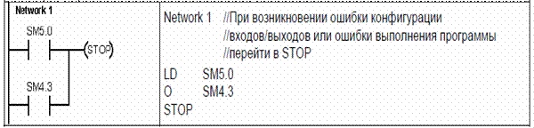
Когда ПЛК обнаруживает нефатальную ошибку, он не переключается в режим STOP. Он только регистрирует событие в памяти SM и продолжает выполнение вашей программы. Однако вы можете спроектировать свою программу так, чтобы она принуждала ПЛК к переходу в состояние STOP, когда обнаруживается нефатальная ошибка. Следующий пример показывает сегмент программы, которая контролирует два глобальных бита нефатальных ошибок и переводит ПЛК в STOP всякий раз, когда устанавливается любой из этих битов.
Фатальные ошибки
Фатальные ошибки заставляют ПЛК прекратить выполнение программы. В зависимости от тяжести фатальной ошибки ПЛК может потерять способность к выполнению некоторых или всех функций. Целью обработки фатальных ошибок является перевод ПЛК в безопасное состояние, из которого ПЛК может реагировать на запросы о существующих сбойных состояниях. Когда ПЛК обнаруживает фатальную ошибку, он переключается в режим STOP, включает светодиоды SF/DIAG (красный) и STOP, заменяет таблицу выходов и выключает выходы. ПЛК остается в этом состоянии до исправления фатальной ошибки.
После устранения фатальной ошибки можно перезапустить ПЛК, используя один из следующих методов:
- Выключите, а затем включите питание.
- Переведите переключатель режимов работы из RUN или TERM в STOP.
- Выберите из STEP 7-Micro/WIN команду меню PLC > Power–Up Reset [ПЛК > Сброс при запуске] для запуска ПЛК. Это заставляет ПЛК перезапуститься и сбросить все фатальные ошибки.
Перезапуск ПЛК сбрасывает состояние фатальной ошибки и выполняет диагностический тест, связанный с включением питания, чтобы проверить, что фатальная ошибка была устранена. Если обнаруживается другая фатальная ошибка, то ПЛК снова устанавливает светодиод ошибки, показывая, что ошибка по-прежнему существует. В противном случае ПЛК начинает нормальную работу. Имеется несколько возможных сбойных состояний, которые могут сделать ПЛК некоммуникабельным. В этих случаях вы не можете отобразить код ошибки ПЛК. Эти типы ошибок указывают на аппаратные отказы, требующие ремонта ПЛК; их невозможно устранить посредством изменений в программе или очистки памяти ПЛК.
Источник: http://plc24.ru/oshibki-v-plk-siemens/
Представлено значение индикаторов (состояние светодиодов, коды ошибок, сообщения на дисплеях) ПЛК Siemens Simatic:
— серия Simatic TI
— серия Simatic S5
— серия Simatic S7
==================================== Simatic TI ========================================
Simatic TI435 (Texas Instrument)
| Состояние светодиода | Описание |
|---|---|
| PWR горит | Питание в порядке. |
| RUN горит | Модуль в режиме RUN. |
| CPU горит | Отсутствуют ошибки CPU. |
| BAT мигает | Батарейка разряжена. |
Simatic TI505 Basic
| Состояние светодиода | Описание |
|---|---|
| MOD GOOD горит | Отсутствуют ошибки. |
| BATT GOOD горит | Батарейка установлена и не разряжена. |
| RUN MODE горит | Модуль в режиме RUN. |
| TEST MODE горит | Модуль в режиме диагностики. |
| STAT 1, STAT 2 | Не используются. |
Simatic TI525, TI535
| Состояние светодиода | Описание |
|---|---|
| RUN горит | Модуль в режиме RUN. |
| BATTERY GOOD горит | Батарейка установлена и не разряжена. |
| P/C GOOD горит | Отсутствуют ошибки. |
Simatic TI545, TI555
| Состояние светодиода | Описание |
|---|---|
| RUN горит | Модуль в режиме RUN. |
| RUN мигает | Аналоги в режиме RUN, дискреты в режиме PROG |
| BAT GOOD горит | Батарейка установлена и не разряжена. |
| BAT GOOD мигает | Батарейка разряжена. |
| CPU GOOD горит | Отсутствуют ошибки. |
Simatic TI505 RBC (Remote Base Controller)
| Номер на дисплее | Описание |
|---|---|
|
0 |
Отсутствуют ошибки. |
|
1 |
В процессе самодиагностики выявлены ошибки. |
|
2 |
Несответствие модуля. |
|
3 |
Превышен интервал ожидания входов/выходов. |
|
4 |
Ошибка чётности RAM. |
|
5 |
Модуль не законфигурирован, в режиме ожидания. |
|
6 |
Несответствие адреса. |
|
7 |
Модуль не законфигурирован, связь установлена. |
|
8 |
Сработал сторожевой таймер. |
|
С |
Модуль законфигурирован, в режиме ожидания. |
{banner_rca-news-1-1}
Simatic TI560, TI565
| Состояние светодиода | Описание |
|---|---|
| POWER GOOD горит | Питание в порядке. |
| BATTERY GOOD горит | Батарейка установлена и не разряжена ниже 2.4В. |
| P/C GOOD горит | Отсутствуют ошибки всех модулей в корзине. |
| CPU GOOD горит | Отсутствуют ошибки CPU. |
| PROG RUN горит | CPU в режиме RUN. |
| MEM GOOD горит | Нет ошибок в модуле памяти. |
| RCC GOOD горит | Контроллер удалённого канала успешно прошёл самодиагностику. |
| Channel горит | Индикация передачи данных по каналу. |
| ACTIVE горит | Индикация активного модуля. |
| STBY горит | Индикация модуля в режиме ожидания. |
| RBU GOOD горит | Индикация сохранности данных модуля. |
| COMGOOD горит | Коммуникации HBU в порядке. |
Simatic TI575
| Состояние светодиода | Описание |
|---|---|
| PCG горит | Отсутствуют ошибки CPU. |
| RUN горит | Модуль в режиме RUN. |
| RUN мигает | Аналоги в режиме RUN, дискреты в режиме PROG |
| BAT горит | Батарейка установлена и не разряжена ниже 2.4В. |
| BAT мигает | Батарейка разряжена. |
| WDT горит | Сработал сторожевой таймер. |
| MOB горит | CPU является активным VME мастером на шине. |
| SYF горит | Проводится самодиагностика после подачи питания либо сбой CPU. |
==================================== Simatic S5 ========================================
Simatic S5 PLC: S5-90U, S5-95U, S5-95F;
Simatic S5-100U: (CPU100, CPU102, CPU103)
| Состояние светодиода при положении переключателя «Run» | Описание |
|---|---|
| RUN зеленый горит, однако ПЛК функционирует неправильно | Ошибка в программе либо сбой входов/выходов. Провести процедуру проверки аппаратной части согласно руководству по ПЛК. |
| STOP красный горит | Неработоспособность ПЛК. Для детальной диагностики необходимо подключение программатора. |
| STOP красный мигает | Ошибка во время загрузки или сохранения программы. |
| BATTERY OFF / LOW горит | Батарейка либо отсутствует, либо установлена неправильно, либо разрядилась ниже 2.8 В. |
Блоки питания S5 PS
| Состояние светодиода PS | Описание |
|---|---|
| POWER SUPPLY OK зеленый горит | Питание в норме. |
| VOLTAGE LOW красный горит | Напряжение на выходе снизилось до недопустимого уровня. |
| FAN FAULT красный горит | Сбой вентилятора. |
| BATT. LOW (BATTERY LOW) желтый горит | Батарейка либо отсутствует, либо установлена неправильно, либо разрядилась ниже 2.7В. |
{banner_rca-news-1-2}
Simatic S5-115U PLC: CPU941, CPU942
| Состояние светодиода | Описание |
|---|---|
| RN зеленый горит | ПЛК в режиме RUN. |
| ST красный горит | После подачи питания — запуск CPU. Всё время — ПЛК в режиме STOP, либо неисправность CPU при команде RUN. |
| ST красный мигает | Аппаратный сбой, ошибка в программе. |
Simatic S5-115U PLC: CPU943, CPU944
| Состояние светодиода | Описание |
|---|---|
| RN зеленый горит | ПЛК в режиме RUN. |
| ST красный горит | ПЛК в режиме STOP, либо неисправность CPU при команде RUN. |
| QVZ (QV) красный горит | Задержка квитирования. ПЛК в режиме STOP. |
| ZYK (ZY) красный горит | Сработал сторожевой таймер. ПЛК в режиме STOP. |
| BASP (BA) красный горит | Блокированы дискретные выходы. ПЛК в режиме запуска или STOP. |
| QVZ (QV), ZYK (ZY), BASP (BA)мигают | Запуск CPU. |
| ST красный мигает | Аппаратный сбой, ошибка памяти. |
Simatic S5-115U PLC: CPU945
| Состояние светодиода | Описание |
|---|---|
| RN зеленый горит | ПЛК в режиме RUN. |
| ST красный горит | ПЛК в режиме STOP, либо неисправность CPU при команде RUN. |
| QVZ красный горит | Задержка квитирования. ПЛК в режиме STOP. |
| ZYK красный горит | Сработал сторожевой таймер. ПЛК в режиме STOP. |
| BASP красный горит | Блокированы дискретные выходы. ПЛК в режиме запуска или STOP. |
| STOP красный медленно мигает | Аппаратный сбой. |
| STOP красный быстро мигает | Необходим общий перезапуск. |
Simatic S5-135U PLC: S-processor CPU921, R-processor CPU922, CPU928
| Состояние светодиода | Описание |
|---|---|
| RUN зеленый горит | ПЛК в режиме RUN. |
| STOP красный горит | ПЛК в режиме STOP, либо неисправность CPU при команде RUN. |
| QVZ, ADF красный горит | Задержка квитирования — не отвечает какой-то из периферийных модулей. ПЛК в режиме STOP. |
| ZYK красный горит | Сработал сторожевой таймер. ПЛК в режиме STOP. |
| BASP красный горит | Блокированы дискретные выходы. ПЛК в режиме запуска или STOP. |
| STOP красный медленно мигает | Ошибка в программа либо произошла запрограммированная остановка CPU. |
| STOP красный быстро мигает | Необходим общий перезапуск, нет модуля памяти либо управляющая программа утеряна. |
Simatic S5-150U PLC: Central unit 924, 925, 926, 927
(6ES5 924-3SA11, 6ES5 925-3SA11, 6ES5 926-3SA11, 6ES5 927-ЗSA11)
| Состояние светодиода | Описание |
|---|---|
| BETRIEB зеленый горит | ПЛК в режиме RUN. |
| STOP красный горит | ПЛК в режиме STOP. |
| NEUSTART ERFODALE желтый горит | Необходим общий перезапуск. |
{banner_rca-news-1-3}
Simatic S5-155U PLC: CPU948
| Состояние светодиода | Описание |
|---|---|
| RUN зеленый горит | ПЛК в режиме RUN. |
| STOP красный горит | ПЛК в режиме STOP. |
| SYS FAULT красный горит | Аппаратный сбой. |
| QVZ, ADF красный горит | Задержка квитирования — не отвечает какой-то из периферийных модулей. ПЛК в режиме STOP. |
| ZYK красный горит | Сработал сторожевой таймер. ПЛК в режиме STOP. |
| BASP красный горит | Блокированы дискретные выходы. ПЛК в режиме запуска или STOP. |
| INIT красный горит | Индикация самодиагностики короткое время после подачи питания. Индикация системных сбоев при свечении во время работы. |
| SI1, SI2 красные горят | Передача данных невозможна по соответствующему порту. Внутренний сбой. |
| STOP красный медленно мигает | Ошибка в программа либо произошла запрограммированная остановка CPU. |
| STOP красный быстро мигает | Необходим общий перезапуск, нет модуля памяти либо управляющая программа утеряна. |
==================================== Simatic S7 ========================================
Simatic S7-200 PLC: CPU212, CPU214, CPU215, CPU216, CPU221, CPU222, CPU224, CPU226
| Состояние светодиода | Описание |
|---|---|
| RUN зеленый горит | ПЛК в режиме RUN. |
| STOP красный горит | ПЛК в режиме STOP. |
| SF (SF/DIAG) горит красным | Аппаратный сбой, ошибка памяти, сработал сторожевой таймер, ошибка программы. |
| SF (SF/DIAG) горит жёлтым | Диагностика либо режим форсирования. |
Simatic S7-1200 PLC: CPU 1211C, CPU1212C, CPU1214C
| Состояние светодиода | Описание |
|---|---|
| STOP/RUN горит зелёным | ПЛК в режиме RUN. |
| STOP/RUN горит оранжевым | ПЛК в режиме STOP. |
| MAINT желтый мигает, STOP/RUN горит оранжевым | Необходимо извлечь карту памяти. |
| STOP/RUN мигает | Загрузка, самодиагностика, обновление прошивки |
| ERROR красный мигает | Ошибка. |
| ERROR красный горит | Аппаратный сбой. |
| MAINT желтый горит | Запрос на обслуживание (необходим сброс памяти). |
| STOP/RUN, ERROR, MAINT мигают | Тест светодиодов либо сбой прошивки. |
Simatic S7-300 PLC: CPU312C, CPU 312 IFM, CPU313, CPU313C, CPU313C-2 DP, CPUCPU314, CPU314C-2 DP, CPU314 IFM, CPU315, CPU315–2 DP, CPU316, CPU316-2 DP, CPU317-2, CPU318-2, CPU319-3
| Состояние светодиода | Описание |
|---|---|
| SF красный горит | Аппаратный сбой, ошибка памяти, сработал сторожевой таймер, ошибка программы, ошибка периферии. |
| BAT F красный горит | Батарейка либо отсутствует, либо установлена неправильно, либо разрядилась. |
| BF красный горит | Ошибка шины на интерфейсе DP. |
| BF1, BF2, BF3 | Ошибка шины на интерфейсе 1, 2, 3. |
| SF DP, BUS F красные горят или мигают | Аппаратный сбой шины, заданы разные скорости обмена, неверная конфигурация, нерабочая станция, slave-устройство не отвечает. |
| DC 5V зеленый горит | Питание +5В в порядке. |
| FRCE жёлтый горит | ПЛК в режиме форсирования. |
| RUN зеленый горит | ПЛК в режиме RUN. |
| STOP жёлтый горит | ПЛК в режиме STOP. |
| STOP жёлтый мигает | Требуется общее стирание CPU. |
Simatic S7-400 PLC: CPU 412-1, CPU412-2 DP, CPU413-1, CPU413-2 DP, CPU414-1, CPU414-2 DP, CPU414-3 DP, CPU416-1, CPU416-2 DP, CPU416-3 DP, CPU417-4
| Состояние светодиода | Описание |
|---|---|
| INTF красный горит | Внутренняя ошибка. |
| EXTF красный горит | Внешняя ошибка. |
| BUS1F красный горит | Ошибка шины на интерфейсе 1 MPI/PROFIBUS DP. |
| BUS2F красный горит | Ошибка шины на интерфейсе 2 PROFIBUS DP. |
| BUS5F красный горит | Ошибка шины на интерфейсе PROFINET. |
| IFM1F, IFM2F красный горит | Ошибка на интерфейсном модуле 1, 2. |
| MAINT жёлтый горит | Запрос на обслуживание (необходим сброс памяти). |
| FRCE жёлтый горит | ПЛК в режиме форсирования. |
| RUN зеленый горит | ПЛК в режиме RUN. |
| STOP жёлтый горит | ПЛК в режиме STOP. |
| STOP жёлтый мигает |
Требуется общее стирание CPU. |
Источник: /engine/api/go.php?go=https://promservis-rostov.ru/
Обсудить на форуме