SECTION 4: T914/916 TROUBLESHOOTING ELECTRICAL PROBLEMS
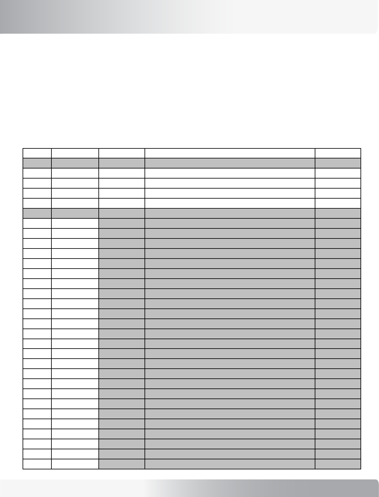
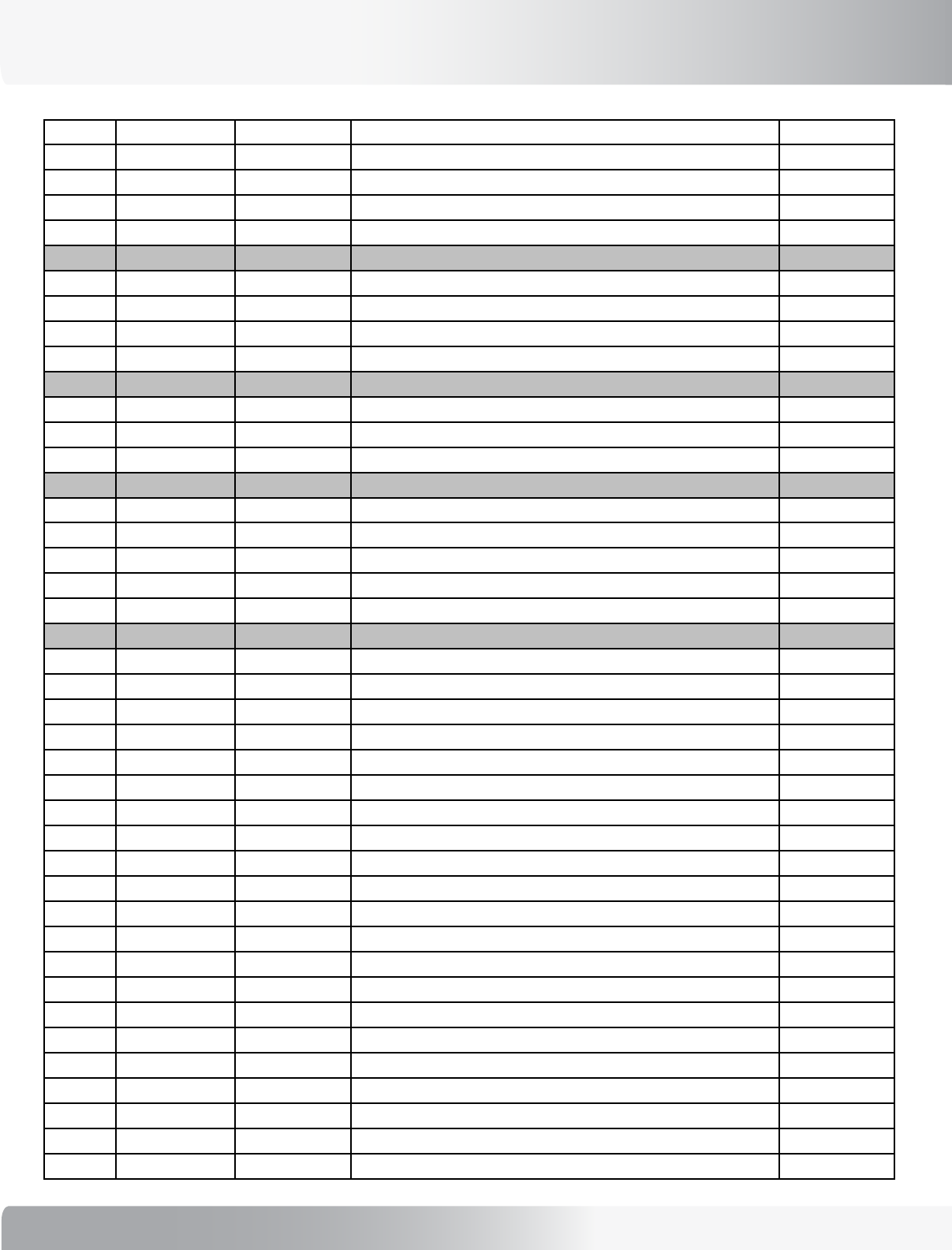
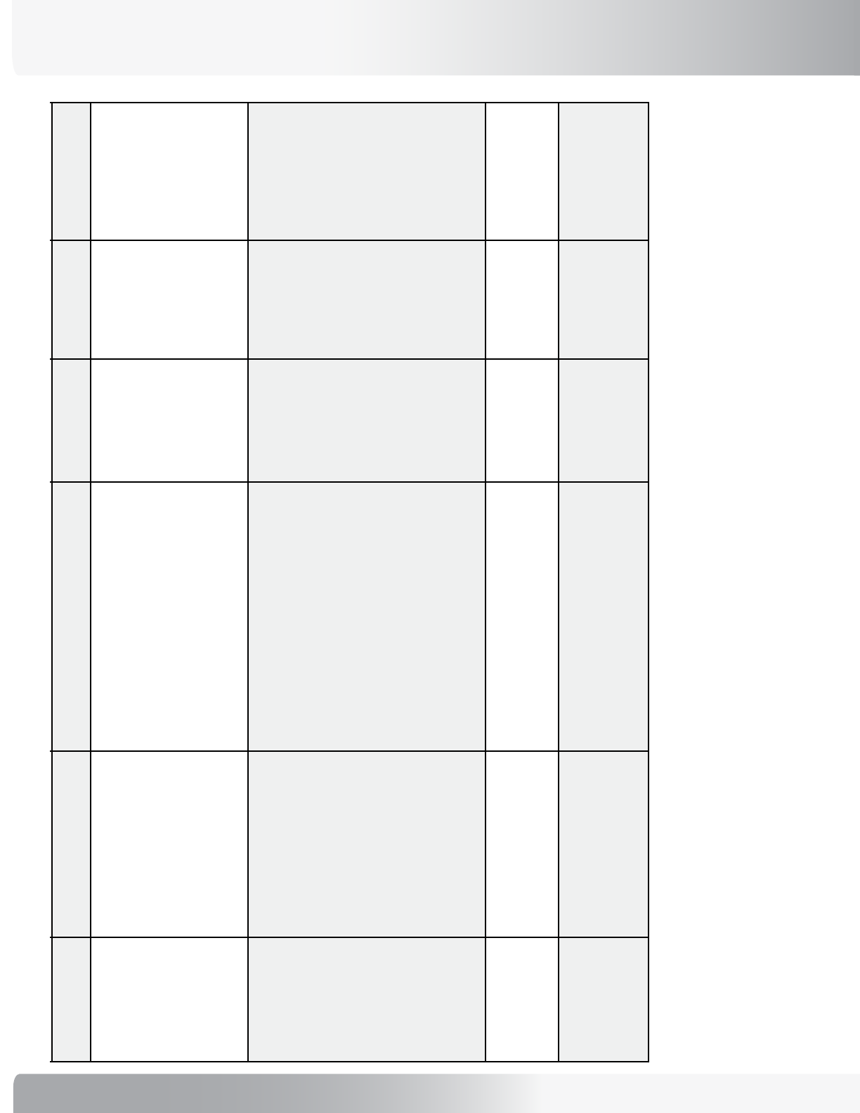
Table 4–3. Error List
Display
Type
TM HW COM
Error
ERROR
TM COM ERROR
Error
DRIVE ERROR
Error
OUT CUR ERROR
Error
BELT OVRLD
Warning
ERROR
SYS OVRLD
Error
ERROR
DRV MON ERROR Error
CONFIG RQRD
Error
GRD LIMIT
Error
ERROR
GRD MOVE
Error
ERROR
SPD CHANGE
Error
ERROR
STUCK KEY
Error
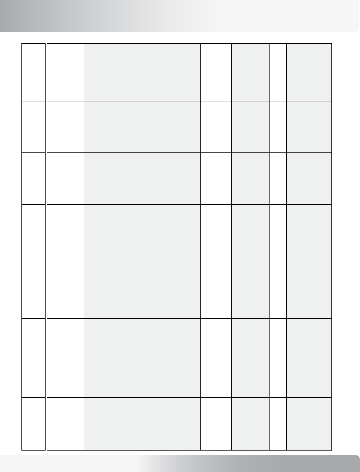
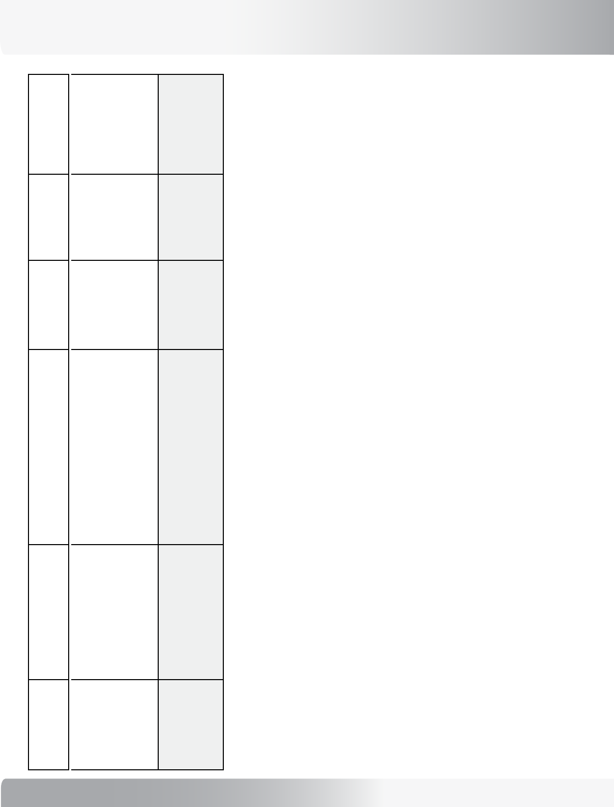
Table 4–4. Production Test Errors (requires special equipment to test console, see
factory)
Display
Type
CS HW COM
Warning
ERROR
CS COM ERROR
Warning
Response
Anytime—Goes to idle. Treadmill
slowly stops.
Anytime—Goes to idle. Treadmill
slowly stops.
Program operation—Goes to idle.
Treadmill stops quickly.
Program operation—Goes to idle.
Treadmill slowly stops.
During movement—Displays
message until the user presses
CLEAR.
Program operation—Goes to idle.
Treadmill slowly stops.
Program operation—Goes to idle.
Treadmill slowly stops.
Start-up—Stops operation.
During change—Goes to idle.
Treadmill slowly stops.
During change—Goes to idle.
Treadmill slowly stops.
Program operation—Goes to idle.
Treadmill slowly stops.
Start-up—Stops operation.
Response
Start-up—Stops CSAFE but
continues user selection.
Anytime—Stops CSAFE but
continues program.
Nautilus® Commercial T9 Series Treadmill Service Manual
Description
Treadmill UART hardware link failure.
Treadmill drive communication failure.
Treadmill drive (VSD) failure, possible
output switching fault recycle power
and determine if failure is intermittent.
Treadmill output current too low.
Treadmill moderate drive overload.
Designed to inform the user that the
belt or deck will need to be replaced
soon.
Treadmill high drive overload.
Treadmill current monitoring circuit
failure.
Treadmill configuration not allowed
or device needs to be configured.
Treadmill grade position outside
limits.
Treadmill grade system detected an
non-requested response.
TM drive is commanded to change
speed but doesn’t.
One of the keypad keys are stuck in
an active state. Reports only «Stuck
key.»
Description
ALL—CSAFE UART hardware link
failure.
ALL—CSAFE communication failure.
55
: Nautilus Nautilus-Treadclimber-Tc916-Users-Manual-494051 nautilus-treadclimber-tc916-users-manual-494051 nautilus pdf
Be Strong.™
P/N: 001-7129 Rev D (5/21/2007)
Service Manual
TreadClimber®, Model TC916
Commercial Series

2
Attention!
this mAnuAl is intended for Authorized nAutilus or nAutilus certified
service personnel And not for the consumer. there Are no user serviceAble
pArts. servicing of the nAutilus commerciAl series treAdmill by other thAn
Authorized nAutilus or nAutilus certified service personnel mAy result in
voiding of the wArrAnty.
for detAiled instructions And informAtion on Assembly And use for the
nAutilus® commericAl series treAdclimber®, model tc916, refer to the
Assembly And owner’s mAnuAls.
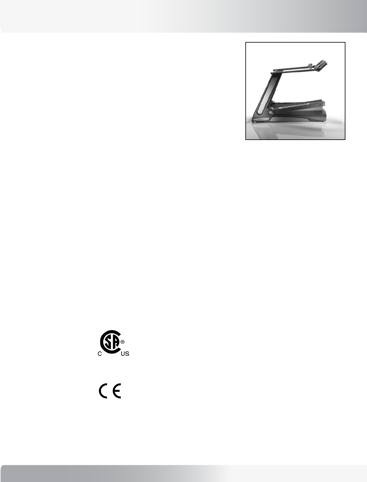
SECURE LONG HAIR AND LOOSE CLOTHING BEFORE WORKING NEAR THE
TREADCLIMBER® WALKING SURFACE OR TREADLES.
7!2.).’
!44%.4)/.
$!.’%2
)—%$)!4%!#4)/.2%15)2%$
#!54)/.

3
Nautilus® TreadClimber®, Model TC916 Service Manual
IMPORTANT SAFETY PRECAUTIONS…………. 4
PRODUCT SPECIFICATIONS ……………………… 6
MECHANICAL SERVICE
1.0 Removing The Console ……………………………………… 7
2.0 Accessing The Console For Programming ……………. 8
3.0 Removing Rear Step …………………………………………. 9
4.0 VSD Assembly Grounding ………………………………… 10
5.0 Removing Uprights …………………………………………. 12
6.0 Removing Base Plastic ……………………………………. 14
7.0 Belt Tension and Alignment …………………………….. 15
8.0 Belt and Deck Replacement …………………………….. 16
9.0 Treadle Adjustment Troubleshooting ………………… 18
10.0 Replacement of Pivot Covers …………………………. 24
11.0 Replacement of Hydraulic Cylinders ……………….. 26
12.0 Vibration Troubleshooting ……………………………… 28
CARDIO CONSOLE CODES ……………………… 30
PARTS LIST
Ordering Replacement Parts ……………………………………….. 33
EXPLODED VIEWS
Working with exploded views ……………………………….. 37
Base Frame with Drive Motor ……………………………….. 37
Base Frame with VSD Motor Control Board ……………. 37
Base Frame with Dependency Link and
Hydraulic System …………………………………………….. 38
Dependency Link …………………………………………………. 38
Treadle Assembly ………………………………………………… 39
Console Upright Assembly, Rear Step and
Console Assembly …………………………………………… 39
Base Frame Covers (Right side.) …………………………….. 40
Base Frame Covers (Left side.) ………………………………. 40
Treadle Deck and Belt Assembly (Right side.) …………. 41
Treadle Deck and Belt Assembly (Left side.) ……………. 41
Treadle Arm Assembly (Right side.) ……………………….. 42
Treadle Arm Assembly (Left side.) …………………………. 42
Treadle Covers — Top and Bottom (Right side.) …………. 43
Treadle Covers — Top and Bottom (Left side.) …………… 43
ROC Bar Assembly ……………………………………………….. 44
Console Upright and Cover Assembly …………………….. 44
Rear Step and Support Platform ……………………………. 45
ELECTRONIC TROUBLESHOOTING
SUMMARY ……………………………………………. 46
WIRING SCHEMATICS ……………………………. 51
IMPORTANT CONTACT NUMBERS ………… 58
TABLE OF CONTENTS

4
IMPORTANT SAFETY PRECAUTIONS — SAVE THESE INSTRUCTIONS
IMPORTANT SAFETY INSTRUCTIONS
The following definition applies to the word “Warning” found throughout this manual:
WARNING — Used to call attention to POTENTIAL hazards that could result in personal injury or loss of life.
WHEN USING ELECTRICAL EQUIPMENT ALWAYS FOLLOW THESE BASIC PRECAUTIONS:
READ ALL INSTRUCTIONS BEFORE USING THE MACHINE.
Read this manual in full before operating the TreadClimber® machine. Failure to follow these guidelines can produce
a serious or possible fatal electrical shock hazard or other serious injury. Consult a qualified electrician as required.
1. The controller Stop Key does not turn off the electrical current to the TreadClimber® exercise machine. The
TreadClimber® machine continues to draw power, even when the controller is off. To avoid electric shock, do not
remove TreadClimber® hood or place hands beneath the TreadClimber® exercise machine while the machine is
plugged into a power source.
2. Do not start the TreadClimber® machine when someone else is standing on the walk belts.
3. Keep walk speed and treadle displacement at the lowest settings when getting on and off the TreadClimber®
machine.
4. Keep the area underneath and around the TreadClimber® exercise machine clear.
5. Never position the TreadClimber® exercise machine with the back end (direction of belt travel) facing a wall or
any other objects such as furniture or other pieces of fitness equipment. Failure to keep the rear space of the
machine clear can prevent safe exit of the TreadClimber® machine in an emergency situation such as falling.
Allow a minimum of four feet behind the TreadClimber® exercise machine.
6. Before each use of this equipment, check the power receptacle for signs of damage. Do not operate the
equipment if the integrity of the power receptacle is in question.
To reduce the risk of burns, electric shock or injury to persons read and
follow all safety warnings and instructions in this manual.
Secure long hair and loose clothing before use.
DO NOT USE NEAR WATER!
7!2.).’
!44%.4)/.
$!.’%2
)—%$)!4%!#4)/.2%15)2%$
#!54)/.

5
Nautilus® TreadClimber®, Model TC916 Service Manual
IMPORTANT SAFETY PRECAUTIONS
7. To avoid potential safety and electrical problems, replace with manufacturer’s specified parts only.
8. This equipment is classified Class I, Type B, ordinary equipment. Not protected against fluid ingress. Rated for
continuous operation. Do not operate this equipment in the presence of flammable anesthetic mixtures.
9. Do not let liquid enter the controller. If it does, the controller must be inspected and tested for safety by an approved
technician before it can be used again.
10. Increased risk due to leakage current can result if this equipment is not grounded properly.
11. The TreadClimber® machine must be on an appropriate, dedicated electrical circuit. Nothing else should be
connected to the circuit.
12. Do not stand on the TreadClimber® TC916’s hood or front trim cover.
13. Close supervision is necessary whenever the machine is used by or near children, invalids, or disabled persons.
Failure to follow the conditions set forth below shall limit, to the extent allowed by law, Nautilus Inc. responsibility for
the safety, reliability, and performance of this equipment.
• The Owner’s Manual must be read in full by each owner and trainer before the product is first used. Each user
must be instructed in the proper use of the TreadClimber® machine and its accessories.
• Do not remove the TreadClimber® hood: dangerous voltages are present. Components are serviceable only by
qualified service personnel.
• The electrical wiring within the TreadClimber® equipment setting and the electrical installation of the
TreadClimber® machine must comply with the applicable local or provincial requirements.
• The equipment must be used in accordance with the instructions for use.
• For further information or instruction on use, maintenance or specifications, please contact your Authorized
Nautilus Fitness Dealer or Service Technician.
6
PRODUCT SPECIFICATIONS
User Weight Capacity: 400 lbs (182 kg)
Speed Range: 0.5 to 6 mph (default set to 4.0 mph) —
[.8 to 9.5 km/h (default set to 6.4 km/h)]
Treadle Displacement Levels: MIN (half the total displacement) and
MAX (full treadle displacement)
Walk Surface (W x L): 21” x 48” defined by two separate left and right treadmill
belt assemblies (treadles), each treadle 10” x 48” in
length, with a 1” or less separation between the belts.
(Metric Walk Surface: [53 x 122 cm].)
Floor Space (W x L): 36” x 70” / 91.5 x 178 cm
TreadClimber® Weight: 684 lbs / 310 kg
Shipping Weight: 806 lbs / 366 kg
Power Requirements: 110-120 Volt, 50/60 Hz, 16 amp dedicated circuit.
220-240 Volt, 50 Hz, 10 amp dedicated circuit.
Warranty: 3 years — parts, 1 year — labor, 1 year — wear items, and
15 years — frame and AC-motor.
(May vary outside the USA.)
Model: TC916
NOTE: All instructions in the manual are given with the orientation
of standing on the TreadClimber® exercise machine facing the
console. The console is the front, while the rear step is the back.
Regulatory Approvals:
Meets:
Safety — EN 60335-1
EMC Directive 89/336/EEC
Machinery Directive — 98/37/EC
Low Voltage Directive — 89/336/EEC
CSA Certified, UL Listed
Meets:
FCC — Part 15
Canadian ICES-003 Regulations for Class A apparatus
Patent Information:
U.S. and International Patents Pending
7
Nautilus® TreadClimber®, Model TC916 Service Manual
MECHANICAL SERVICE
1.0 — REMOVING THE CONSOLE
Tools Needed:
• Phillips head screw driver
• 5/32 Allen bit
1-1: Turn off the unit and unplug from the wall outlet.
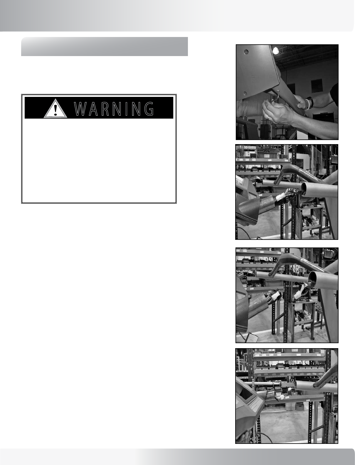
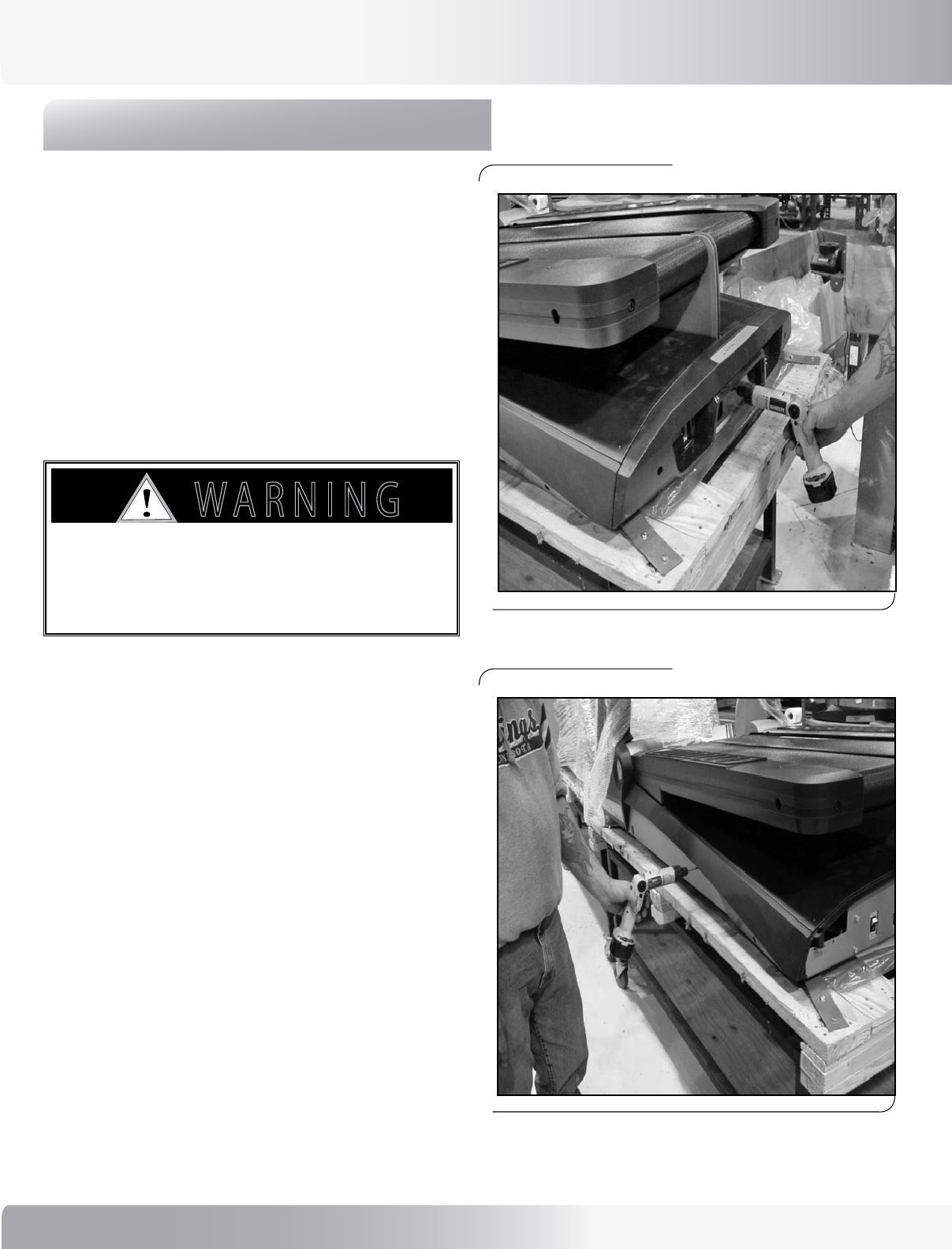
1-2: Remove Button head screws (P/N- SM24162) on
underside of the handles on each side (see Figure 1-1).
1-3: Gently pull console off evenly from both sides until
cables are exposed (see Figure 1-2).
1-4: Disconnect the 2 cables on the left side
(see Figure 1-3).
1-5: Disconnect the 1 cable on the right side
(see Figure 1-4).
NOTE: To replace console, reverse instructions.
Figure 1-1
Figure 1-2
Figure 1-3
Figure 1-4
to Avoid electricAl shock or
dAmAge to the unit you must
power off the unit And mAke
sure All power hAs been drAined
from the unit And cApAcitors by
ensuring there Are no lighted
leds on the console.
7!2.).’
!44%.4)/.
$!.’%2
)—%$)!4%!#4)/.2%15)2%$
#!54)/.
8
MECHANICAL SERVICE
2.0 — ACCESSING THE CONSOLE FOR
PROGRAMMING
Tools Needed:
• Phillips head screw driver
2-1: Turn off the unit.
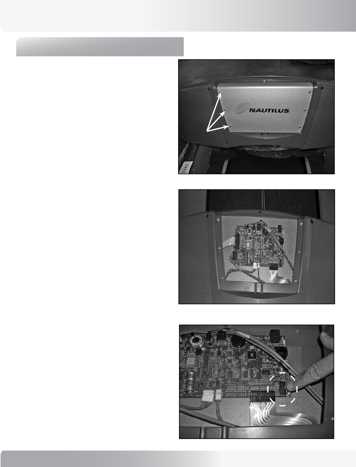
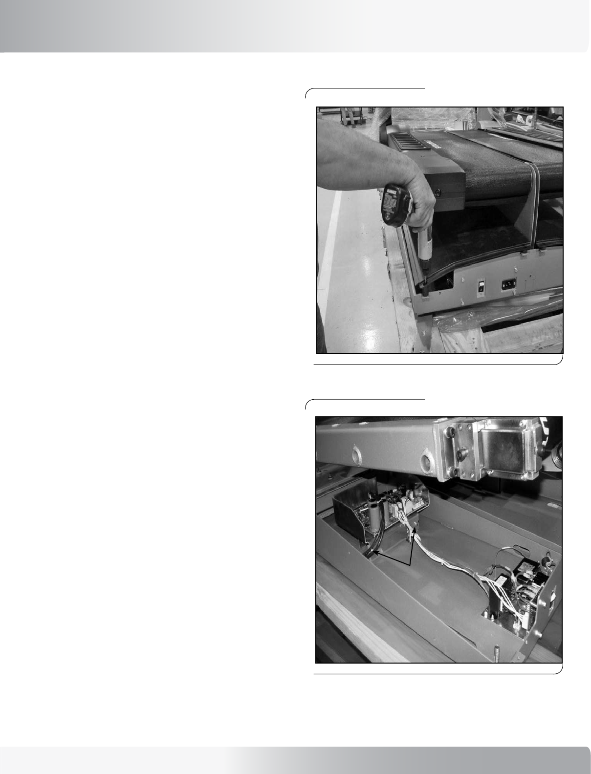
2-2: Remove six (6) screws (P/N — SM41271) from back
side of console to remove cover and gain access for
programming (see Figure 2-1 and Figure 2-2).
2-3: Attach FISP connector for software programming to
this connection (see Figure 2-3).
2-4: Turn on the unit.
2-5: The LED on the FISP will blink momentarily, then stay
on solid.
2-6: Turn off the unit.
2-7: Remove FISP connector, replace cover and reattach
with six (6) screws (P/N — SM41271).
Figure 2-2:
Exposed console circuit board.
Figure 2-1
3 screws per side
Figure 2-3
9
Nautilus® TreadClimber®, Model TC916 Service Manual
3.0 — REMOVING REAR STEP
Tools Needed:
• Phillips head screw driver
• 5/32 Allen bit
3-1: Unplug the unit from the power source and ensure
that all power has been drained from the unit.
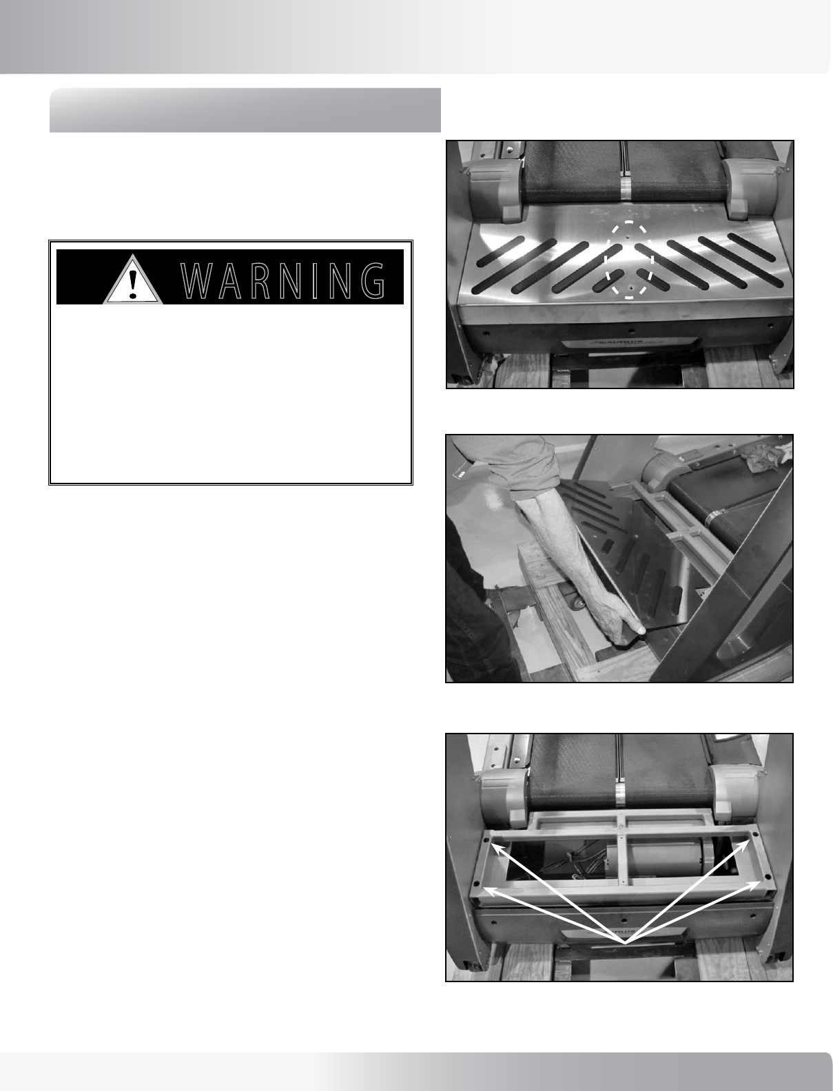
3-2: Remove two (2) middle screws from Rear Step Cover
(see Figure 3-1).
3-4: Lift and slide step cover plate back to remove
(see Figure 3-2).
3-3: Remove four (4) screws from Step Weldment (see
Figure 3-3).
3-5: Replace rear cover by sliding back into place and re-
installing four (4) outer screws.
3-6: Place Step cover onto Step weldment and reattach
with two (2) screws (see Figure 3-2 and Figure 3-1).
Removing the step cover plate provides access to the I/O
cables needed for the removal of the uprights.
to Avoid electricAl shock or dAmAge
to the unit you must power off the
unit And mAke sure All power hAs been
drAined from the unit And cApAcitors by
ensuring there Are no lighted leds on
the console.
7!2.).’
!44%.4)/.
$!.’%2
)—%$)!4%!#4)/.2%15)2%$
#!54)/.
MECHANICAL SERVICE
Figure 3-2
Figure 3-1
Two Middle Screws
Figure 3-3
Four Outer Screws
10
MECHANICAL SERVICE
4.0 — VSD ASSEMBLY GROUNDING
Parts Affected:
• Front Trim Cover — P/N: SM17652
• Right Pan Cover — P/N: SM17653
• Right Side Cover — P/N: SM17655
• VSD Assembly, TC916 — P/N: SM17688
• Flat Washer, 1/4 ID x 5/8 OD — P/N: SM22047
• Screw, .250-20 x .75, HX Wash HD —
P/N: SM27594
Tools Needed:
• 1/8 Allen Bit
• 3/8 inch Socket or Open End Wrench
To Install New VSD Ground Improvement:
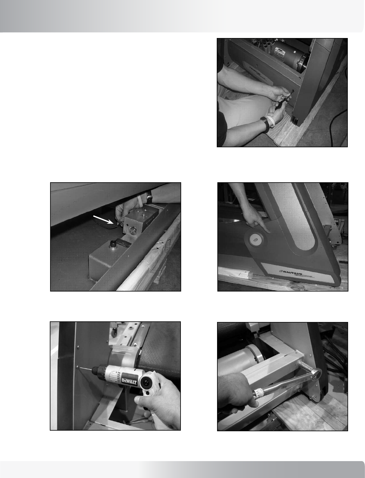
4-1: Adjust Right Treadle to maximum step height.
4-2: Remove three (3) screws from Front Trim Cover (P/N
— SM17652). See Figure 1.
4-3: Remove four (4) screws from Right Side Cover (P/N
— SM17655). See Figure 2.
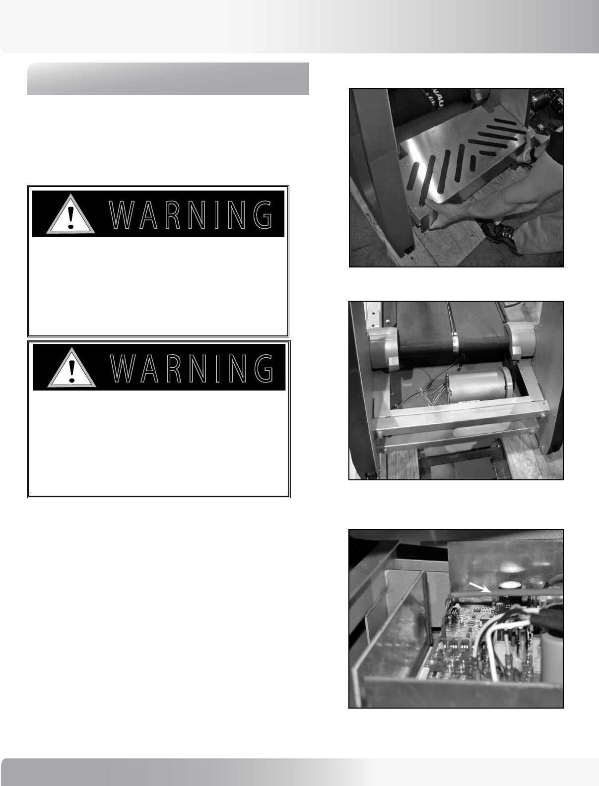
4-4: Remove two (2) screws from Right Pan Cover to access
the VSD Assembly (see Figure 3 and Figure 4).
CAUTION: ENSURE THAT ALL LIGHTS ARE OFF
ON THE VSD ASSEMBLY BEFORE
CONTINUING — OTHERWISE, YOU MAY
DAMAGE THE BOARD.
4-5 Disconnect and mark cables (for reconnecting in later step)
from the VSD board.
Figure 1:
Figure 2:
To avoid the risk of electrocution, shock or
mechanical injury, before performing this
maintenance, ensure that the machine is
unplugged.
7!2.).’
!44%.4)/.
$!.’%2
)—%$)!4%!#4)/.2%15)2%$
#!54)/.
11
Nautilus® TreadClimber®, Model TC916 Service Manual
MECHANICAL SERVICE
4-6: Remove the two (2) VSD Bracket Screws (P/N
— SM27594), then remove the VSD Assmebly (see
Figure 4).
4-7: Position the new VSD Assembly in place and attach
with the two (2) bracket screws.
4-8: Reconnect the previously marked cables to the VSD
Assembly.
4-9: Reattach all covers and verify that all machine
functions are working properly.
Figure 3:
Figure 4:
VSD Bracket
Screws
12
5.0 — REMOVING UPRIGHTS
Tools Needed:
• 1/8 Allen bit
• 5/32 Allen bit
• 3/4 inch Socket
• Phillips head screw driver
5-1: Remove the Front Trim Cover (P/N — SM17652), Left
Side Cover (P/N — SM17656), Left Pan Cover (P/N
— SM17654) and Right Side Cover (P/N — SM17655),
Right Pan Cover (P/N — SM17653).
5-2: Remove the Rear Step Cover and weldment (see
Figure 5-1).
5-3: Remove the Rear Plastic Cover (P/N — SM17659 to
access the Upright Cables. (See Figure 5-2 and Figure
5-4.)
5-4: Disconnect three cables as follows:
A) From the VSD Board. See Figure 5-3.
Figure 5-1
Figure 5-2
Figure 5-3: I/O Connectors.
MECHANICAL SERVICE
detAching And moving the upright portion of
this product requires two people! you must
hAve A minimum of two people to properly
support the heAvy upright structure so the
console does not fAll And cAuse dAmAge to the
unit.
7!2.).’
!44%.4)/.
$!.’%2
)—%$)!4%!#4)/.2%15)2%$
#!54)/.
to Avoid electricAl shock or dAmAge
to the unit you must power off the
unit And mAke sure All power hAs been
drAined from the unit And cApAcitors by
ensuring there Are no lighted leds on
the console.
7!2.).’
!44%.4)/.
$!.’%2
)—%$)!4%!#4)/.2%15)2%$
#!54)/.
Cable Connector
13
Nautilus® TreadClimber®, Model TC916 Service Manual
Figure 5-4
Figure 5-5 Figure 5-6: Lower plastic parts.
Figure 5-7 Figure 5-8
B) From the Encoder Assembly PC board (Not
shown).
NOTE: The Encoder is under the Treadles and
you will have to reach into the machine to
disconnect.
C) From the Hydraulic Cylinder. See Figure 5-5.
5-5: Remove the Right Lower Cover (P/N — SM17657) and
Left Lower Cover (P/N — SM17658). See Figure 5-6 and
5-7.
5-6: Remove four (4) upright weldment bolts (see Figure
5-8).
Cylinder control
cables located
here.
MECHANICAL SERVICE
14
6.0 — REMOVING BASE PLASTIC
Tools Needed:
• Phillips head screw driver
• 1/8 Allen bit
6-1: Remove three (3) front plastic screws
(see Figure 6-1).
6-2: Remove right and left side plastic covers — four (4)
screws each side (see Figure 6-2).
6-3: Remove right and left side pan covers — two (2)
screws each side (see Figure 6-3 and Figure 6-4).
Figure 6-1
Figure 6-2
Figure 6-3
Figure 6-4:
Pan without
covers.
MECHANICAL SERVICE
to Avoid electricAl shock or dAmAge
to the unit you must power off the
unit And mAke sure All power hAs been
drAined from the unit And cApAcitors by
ensuring there Are no lighted leds on
the console.
7!2.).’
!44%.4)/.
$!.’%2
)—%$)!4%!#4)/.2%15)2%$
#!54)/.
15
Nautilus® TreadClimber®, Model TC916 Service Manual
7.0 — BELT TENSION AND ALIGNMENT
Parts Affected:
• Left Treadle Assembly — P/N 17623
• Right Treadle Assembly — P/N 17617
• Treadle Belt — P/N — SM17860
Tools Needed:
• 5/16 Allen bit
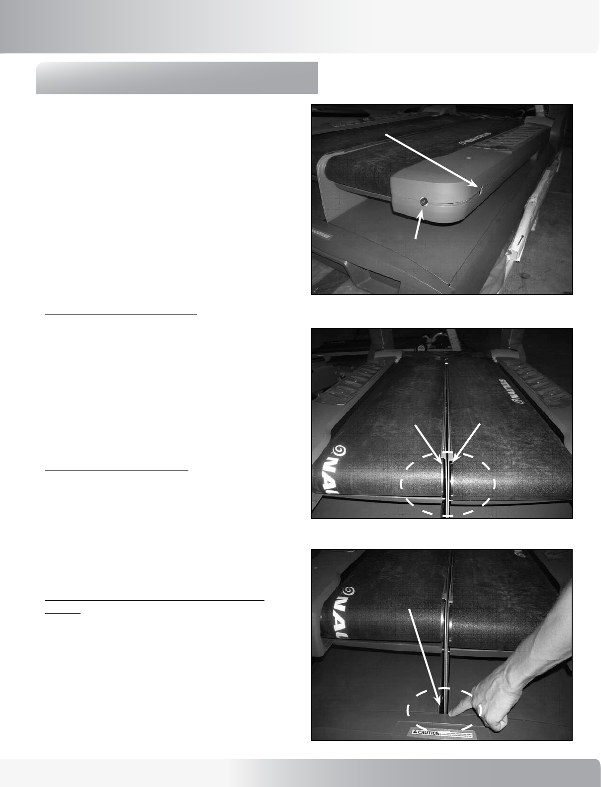
Belt alignment and tensioning adjustments (see Figure 1).
NOTE: See Figure 1 for belt and tensioning adjustment
screws. The adjustments are the same on the right
and left side of the machine.
To check for proper belt alignment:
7-1: Operate TreadClimber® machine so belt is running at
2.5 — 3 mph (4 — 4.8 km/h).
7-2: Belt is aligned when 1/8” (3.2 mm) of roller is
showing (see Figure 2).
7-3: Tightening alignment screw clockwise moves belt
out, loosening screw counter-clockwise moves belt
in.
To check for proper belt tension:
7.1-1: Tension is correct when the gap between the
treadles is even and centered. See Figure 3 for an
example of INCORRECT tension.
7.1-2: Tighten (clockwise turn) or loosen (counter—
clockwise turn) tensioning adjustment located at
the end of the treadle.
To completely loosen belt if you want to start from
scratch:
7.2-1: Totally loosen alignment screw by turning counter-
clockwise.
7.2-2: Loosen tensioning screw by turning counter—
clockwise.
Figure 1
Figure 2
Figure 3
Alignment adjustment
Tensioning adjustment
Tension is too tight, treadle guards are
rubbing. To correct loosen tensioning
adjustment screw.
Belts are correctly aligned when
1/8 inch of roller is showing.
MECHANICAL SERVICE
16
8.0 — BELT AND DECK REPLACEMENT
Tools Needed: 7/16 & 3/4 Wrench or Socket
3/8 Allen Socket
1/8, 5/32 & 5/16 Allen Wrench
Phillips screwdriver
wood blocks 4-6 inch (10-15 cm) thick
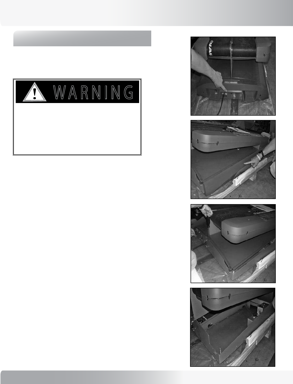
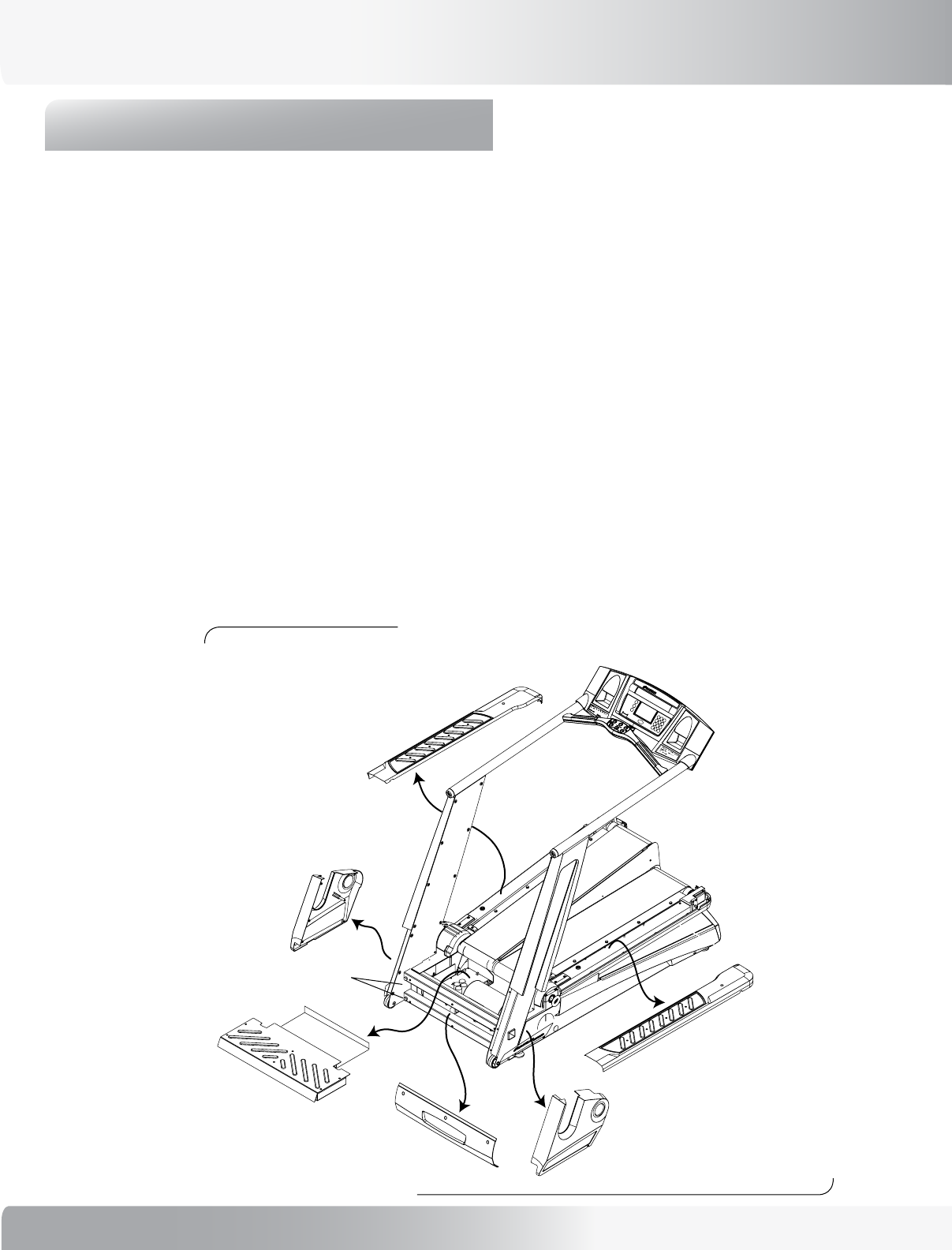
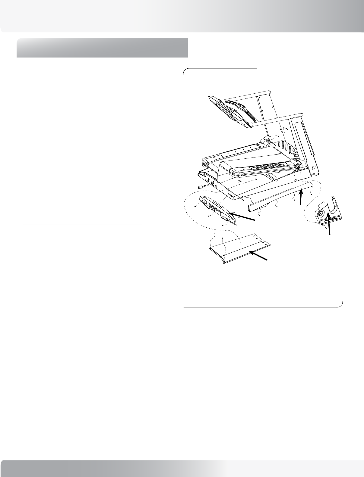
8-1: Remove rear cover and rear step (see Figure 1 and
Figure 2).
8-2:
Remove side pivot covers, side frame covers, front
cover, bottom frame covers and treadle covers (see
Figure 1).
8-3: Loosen four 1/2” — 13 bolts holding uprights to frame
using 3/4 socket or wrench.
8-4: Remove pivot casting bolts with 5/32 Allen wrench.
8-5: Lift console upright to remove pivot castings.
8-6:
Relieve all tension on the belt by completely
loosening the alignment screw and then the
tensioning screw.
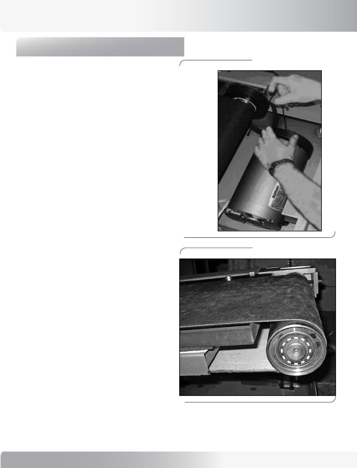
8-7: Remove end casting with front roller using 5/16 Allen
wrench (see Figure 3).
8-8: Remove deck screws with a 7/16 socket or wrench.
8-9: Remove deck (see Figure 4).
8-10: Brace treadles with blocks 4-6 inches (10-15 cm)
thick (see Figure 5).
8-11: There are 2 treadle bolts and 4 treadle pivot bolts
on each side. Remove these 6 bolts on one side,
and loosen the 2 treadle bolts and remove the 4
pivot bolts using a 3/8 Allen and socket wrench
(see Figure 6).
NOTE:
Remove one belt at a time. Replace the bolts,
deck and belt before proceeding to the other
side.
8-12: Lift treadle to create clearance for walk belt to slide
between upright and end of roller (see Figure 7).
8-13: Replace belt and deck using the reverse order of
steps 11 through 1.
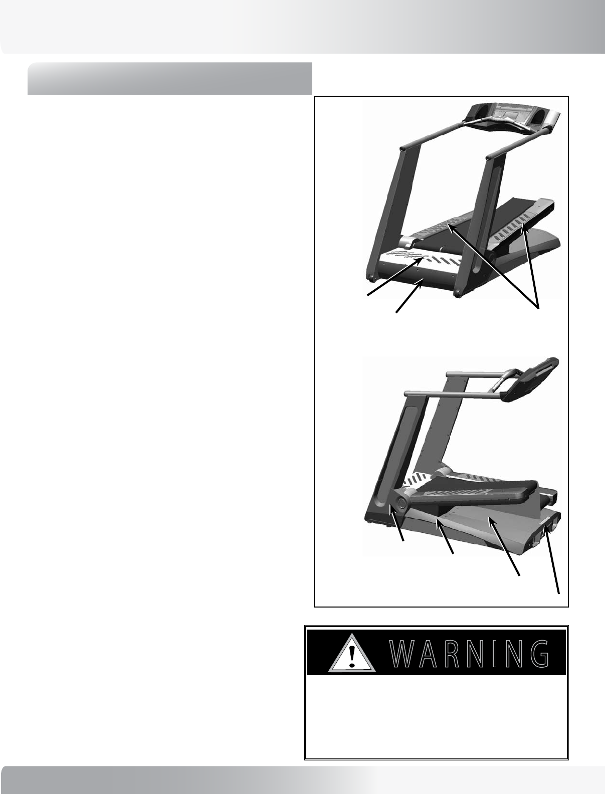
Rear Cover
Rear Step
Side Pivot Covers
Side Frame Covers
Front Cover
Bottom Frame Covers
Treadle Covers:
4 covers total —
top/bottom, and
left/right.
Figure 1
MECHANICAL SERVICE
ALWAYS UNPLUG THE TREADCLIMBER® BEFORE
PERFORMING ANY TREADLE REPAIR!
USE CAUTION WHEN WORKING ON THE DECK OR
REPLACING THE BELTS. SERIOUS INJURY TO FINGERS
AND HANDS MAY OCCUR IF THE TREADLES ARE NOT
PROPERLY SUPPORTED WITH BLOCKS.
7!2.).’
!44%.4)/.
$!.’%2
)—%$)!4%!#4)/.2%15)2%$
#!54)/.
17
Nautilus® TreadClimber®, Model TC916 Service Manual
BELT AND DECK REPLACEMENT CONTINUED:
Figure 2: Rear cover and rear step removed.
Figure 3: Removing end casting with Allen
wrench.
Figure 5: Brace treadles with wooden blocks.
Figure 6: Remove treadle bolts & pivot bolts; 4
bolts per side.
Figure 4: Remove deck. Figure 7: Lift treadle to create clearance.
MECHANICAL SERVICE
18
MECHANICAL SERVICE
9.0 — TREADLE ADJUSTMENT
TROUBLESHOOTING
Parts Affected:
• Treadle Assembly
• Hydraulic Cylinder
Tools Needed:
• Phillips Screwdriver
• Hex Key
• Socket Wrench
• Flat Screwdriver
Troubleshooting Treadle Steps:
A:
DETERMINING IF THERE IS A
PROBLEM WITH THE HYDRAULIC
CYLINDER (EITHER AIR IN THE
SYSTEM OR CONTAMINANTS IN
THE OIL AND VALVES), OR IN THE
CONNECTING HARDWARE:
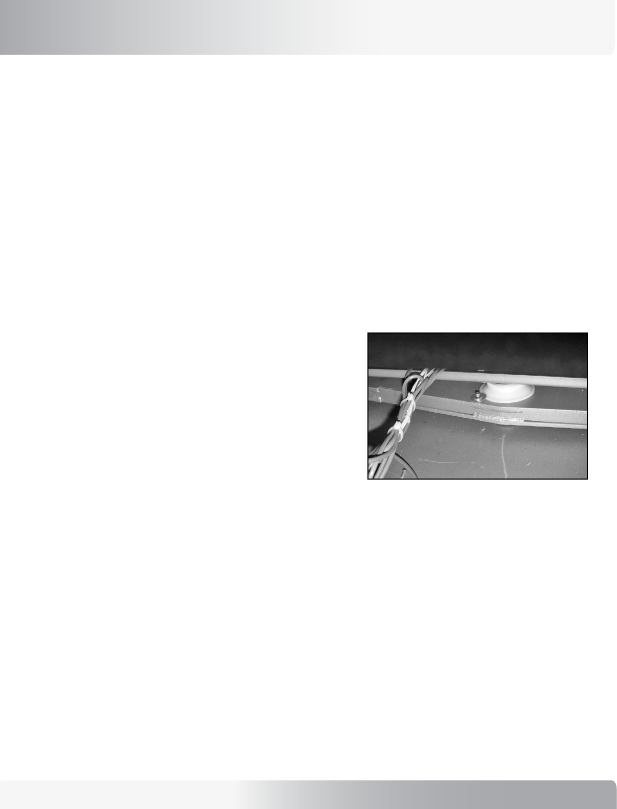
NOTE: Two people are required to complete this step. One
person standing on the treadles, while the other
person adjusts the encoder.
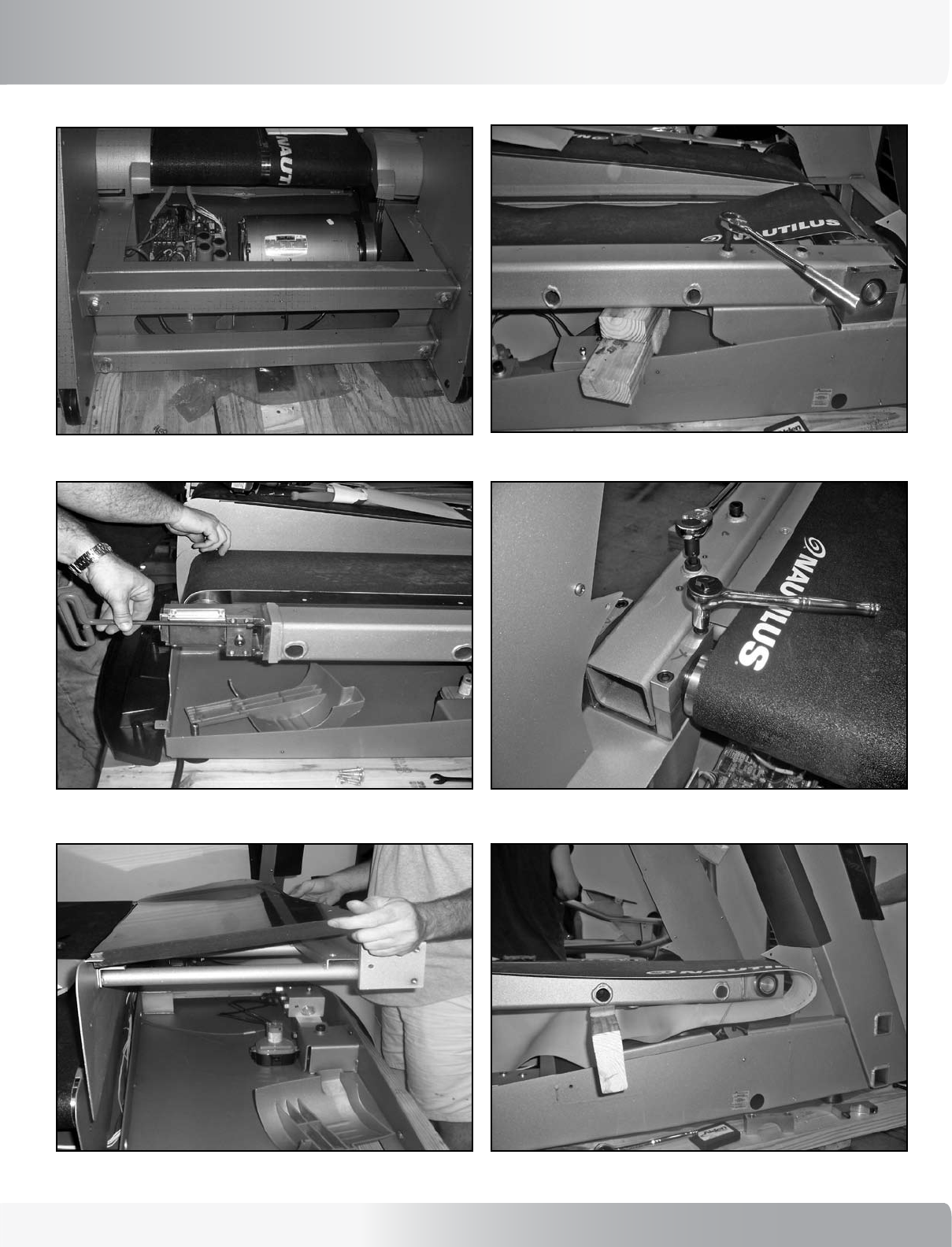
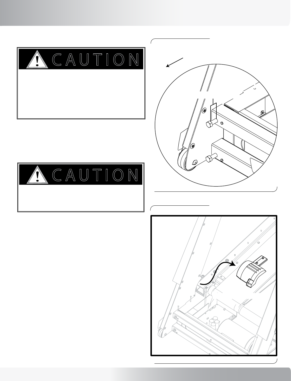
9A-1: Disconnect the two leads from the hydraulic
cylinder. This will ensure that the hydraulic cylinder
valve should be closed (see Figure A-1).
9A-2: With the treadles in the locked position, pull up
and down on both the right and left treadles (see
Figure A-2).
If the right treadle is loose (moves more than ½”)
and the left treadle is solid, this points to loose
hardware. Go to Step 9A-4 in Section A.
If both right and left treadles are loose, then
the problem could be loose hardware or a bad
cylinder.
Figure A-1
Figure A-2
Figure A-3
Figure A-4
19
Nautilus® TreadClimber®, Model TC916 Service Manual
MECHANICAL SERVICE
Figure A-5
Figure A-6
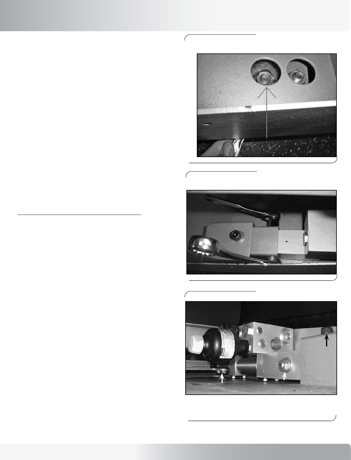
9A-3: Check the cylinder by feeling the shaft of the
cylinder and pulling up and down on the left
treadle. If the cylinder shaft moves in and out of
the cylinder body by more than an 1/8th inch (3.2
mm), then the cylinder will need to be replaced.
9A-4: If the problem is not in the cylinder, then check the
hardware at the following locations and tighten as
necessary:
a) On the rod-end entering the cylinder, the jam
nut should be tight to the rod-end, and there
should only be 2 or 3 threads showing on the
opposite side of the jam nut. This insures that
the rod-end is fully engaged in the cylinder.
b) The connection between the rod-end and the
dependency weldment. See Figure A-6. Tighten
as necessary.
c) The connection between the dependency and
the rod-end on the opposite (right) side (see
Figure A-4 and A-5).
d) The center bolt at the center of the dependency
weldment (see Figure A-6).
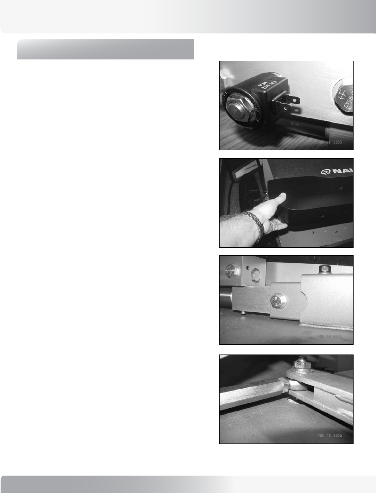
e) Check both the horizontal and the vertical bolts
connecting the cylinder to the coupler and the
coupler to the weldment of the pan. The bolts
should be torqued to 75 ftlbs (105 Nm). See
Figure A-7.
Figure A-7
20
MECHANICAL SERVICE
B:
IF THE PROBLEM IS NOT IN
THE HYDRAULIC CYLINDER OR
THE CONNECTING HARDWARE,
THEN PERFORM THE FOLLOWING
ELECTRONIC AND SOFTWARE
CHECKS:
9B-1: Turn the unit on. Move the treadles up and down
until they come to a locked position.
9B-2: If the treadles do not come to a locked position
within 2 to 4 steps, then position the treadles level.
Turn the power off. Wait 10 seconds, then turn the
power on. Move the treadles up and down until they
come to a locked position.
9B-3: If the treadles still do not come to a locked position,
then check the treadle center position on the encoder
PCB, as follows:
a) Remove the rear step. Enter diagnostic mode.
From the Intro screen, press [Speed UP] [6]
[ENTER]. The display will read “DIAGNOSTIC”.
b) Press the [Speed UP] or [Speed DOWN] keys
to scroll through the options until “TREADLE
CENTER” is displayed. Press [ENTER]. This will
release the treadles to allow them to be moved
by hand.
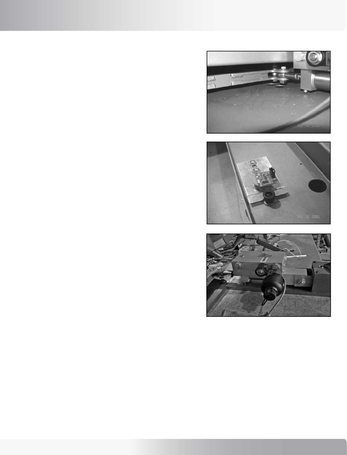
c) Slowly move the treadles up and down while
looking at the encoder PCB mounted in the center
of the dependency mechanism. There is a light on
the PCB. Note the position of the treadles when
the light on the PCB comes on. The treadles
should be parallel within 1 inch (2.5 cm) of each
other when the PCB light comes on (see Figure
B-1).
d) If the treadles are not parallel when the encoder
PCB light comes on, then the large encoder wheel
will need to be adjusted. Go to section C of this
section in the Service Manual to re-center the
encoder wheel. Be sure to verify that the large
encoder wheel is firmly fixed to the dependency
Figure B-1
21
Nautilus® TreadClimber®, Model TC916 Service Manual
MECHANICAL SERVICE
C:
TO RE-CENTER THE LARGE
ENCODER WHEEL ATTACHED TO THE
DEPENDENCY MECHANISM, FOLLOW
THESE STEPS:
9C-1: Loosen the set screw. Be sure that the treadles are
level.
9C-2: SLOWLY rotate the large encoder wheel in
one direction by hand or use a small flat-blade
screwdriver on the teeth of the encoder wheel.
Rotate the wheel until the light comes on the
encoder PCB.
9C-3: With the treadles level and the encoder light on,
tighten the set screw holding the large encoder
wheel in place (see Figure C-1).
9C-4: Go to section D to make sure that the large encoder
wheel is not slipping during treadle movement.
Figure C-1
mechanism. This can be checked by verifying
the number of encoder counts in the diagnostic
software. See section D of this bulletin to check
the encoder counts.
e) If the treadles are parallel or within 1 inch of
parallel when the encoder PCB light comes one,
reset the treadle center in the software mode.
Go to Section E of this bulletin to reset the
treadle center in the software mode.
22
MECHANICAL SERVICE
D:
TO CHECK THE ENCODER RANGE
OF MOVEMENT AND TO MAKE
SURE THE LARGE ENCODER
WHEEL IS NOT SLIPPING DURING
MOVEMENT, FOLLOW THESE
STEPS:
9D-1: From the Intro screen, press [Speed UP] [6] [EN-
TER]. The display will read “DIAGNOSTIC”. Press
the [Speed UP] or [Speed DOWN] keys to scroll
through the options until “TREADCLIMBER” is
displayed. Press [ENTER].
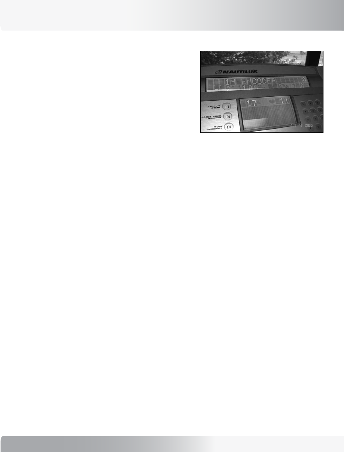
9D-2: The top line of the display will read: “ENCODER
— XX” (see Figure D-1). Press the [9] key. The PWM
value, which is on the lower line center position,
will change from 255 to 189, and the treadles will
be free to move up and down.
9D-3: Shift your weight to the left side, allowing the left
treadle to fall all the way to the bottom. With the
left treadle held at the bottom, note the number
displayed on the top line, far right. It should read
in the range between [ — 30 ] and [ — 50 ]. Remem-
ber the number.
9D-4: Next, shift your weight to the right side, allowing
the right treadle to fall all the way to the bottom.
The number displayed on the top line, far right
should read in the range between [ 30 ] and [ 50].
Remember the number.
9D-5: Calculate the total range between the two num-
bers. The absolute value of the negative number
(left side down) added to the positive number (right
side down), represents the total encoder range
of motion. This number should be in the range
between 70 and 90 total counts.
9D-6: If the range is less than 70, check to make sure the
large encoder wheel is not slipping.
Figure D-1
To check if the encoder wheel is slipping, slowly move the treadles up and down. The encoder value
displayed will hesitate and not count up or down. In other words, the encoder value will not change, even though
there is movement in the treadles. If the encoder value does not change during movement of the treadles, then
the encoder wheel is slipping and needs to be tightened or replaced.
23
Nautilus® TreadClimber®, Model TC916 Service Manual
MECHANICAL SERVICE
E:
TO RESET THE TREADLE CENTER
IN SOFTWARE TO MATCH THE
TREADLE CENTER ON THE
ENCODER, FOLLOW THESE STEPS:
9E-1: From the Intro screen, press [Speed UP] [6]
[ENTER]. The display will read “DIAGNOSTIC”.
Press the [Speed UP] or [Speed DOWN] keys
to scroll through the options until “TREADLE
CENTER” is displayed. Press [ENTER].
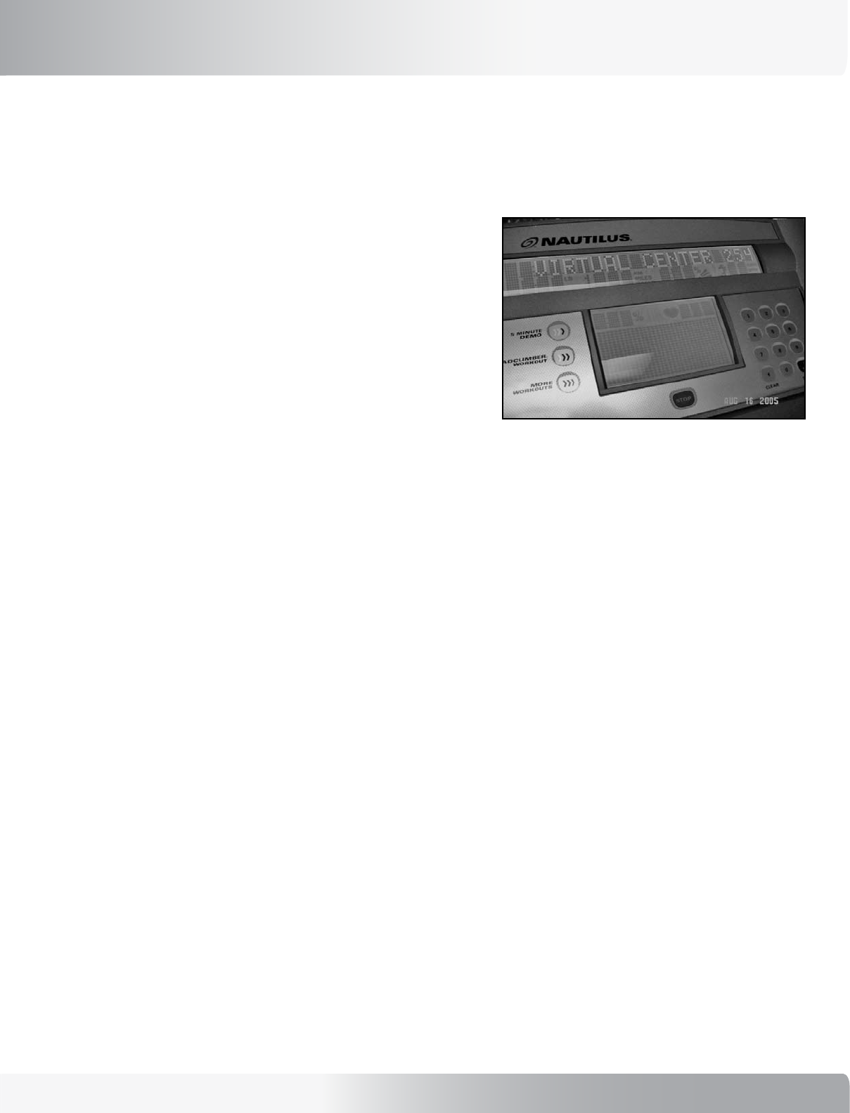
9E-2: The top line of the display will read: “VIRTUAL
CENTER — XX” (see Figure E-1). With the treadles
held parallel, press the [STOP] key. The number
on the display will be used by the software for the
center point position. When STOP key is pressed
the number will change to a value between 0
to 255. This means the treadle center in the
software has been recalibrated to match the
center position of the encoder.
9E-3: Press [CLEAR] twice to exit the Diagnostic mode.
Move the treadles up and down until the treadles
lock. Verify that the treadles lock parallel to each
other or within 1” of parallel.
9E-4: If the treadles do not lock parallel or close to
parallel, then 1) recheck the center position on the
encoder PCB (section B); 2) recheck the encoder
range (section D); 3) recheck the treadle center in
software (section E).
Figure E-1
24
MECHANICAL SERVICE
10.0 — REPLACEMENT OF PIVOT COVERS
Parts Affected:
• Right Pivot Cover — P/N 17660
• Left Pivot Cover — P/N 17661
Tools Needed:
See Figure 1 for Steps 10-1 thru 10-4.
10-1: Remove Rear Step (P/N -17733) and Step Plate (P/N — 17591).
10-2: Remove Rear Plastic Cover (P/N — 17659).
10-3: Remove right Treadle Cover (P/N — SM17731 and P/N — SM17666), then remove the left Treadle Cover (P/N — SM17332
and P/N — 17667).
10-4: Remove right and left Upright Lower Plastic Pivot Covers (P/N — SM17657 and P/N — 17578).
Figure 1
Rear Step
Rear Plastic Cover
Lower Plastic Cover
Lower Plastic Cover
Treadle Top Cover
Treadle Top Cover
Upright Attachment
Bolts
• 3/16 Allen Wrench
• 5/32 Allen
• 1/8 Allen
• Phillips Screwdriver
• 3/4 inch Socket
• 3/4 inch Wrench or Open Ended Wrench
• Wedge support or flat head screwdriver to use as
a wedge
25
Nautilus® TreadClimber®, Model TC916 Service Manual
MECHANICAL SERVICE
10-5: Loosen 4 inside bolts (2 on each side) that attach the
upright (P/N — 17626) to base frame (see Figure 2).
10-6: Slide the upright (P/N — 17626) backwards, away
from the front of the unit to expose the right and left
pivot covers. Secure in the back position (see Figures
1 &2).
10-7: Remove right and left pivot covers (P/N — 17660 &
17661). This may require a twisting motion (see
Figure 3). Install replacement pivot cover in its place.
10-8: Reassemble the unit in reverse order from Step 6
to Step 1: Slide the uprights forward into place;
tighten the four inside bolts; reinstall the right and
left lower plastic covers; reinstall the right and left
treadle top covers; reinstall rear plastic cover; and
reinstall rear step and step plate weldment.
1/2” to 3/4” MAX
Slide Uprights Back
1/2 INCH MAXIMUM
Left Pivot Cover
Figure 3
Figure 2
7!2.).’
!44%.4)/.
$!.’%2
)—%$)!4%!#4)/.2%15)2%$
#!54)/.
DO NOT REMOVE BOLTS COMPLETELY. TO DO
SO WILL CAUSE THE UPRIGHT SUPPORTS TO
FALL RESULTING IN DAMAGE TO THE UNIT AND
POSSIBLE INJURY TO BYSTANDERS. THE BOLTS
MUST NOT BE BACKED BEYOND A MAXIMUM
DISTANCE OF 1/2 INCH. SEE FIGURE 2.
7!2.).’
!44%.4)/.
$!.’%2
)—%$)!4%!#4)/.2%15)2%$
#!54)/.
SLIDING THE UPRIGHTS MAY REQUIRE
ASSISTANCE. DO NOT ATTEMPT TO LIFT THE
UNIT.
(1.3 CM)
26
11.0 — REPLACEMENT OF HYDRAULIC
CYLINDERS
Parts Affected:
• Front Cover — P/N 17652
• Left Side Cover — P/N 17656
• Left Lower Pan Cover — P/N 17654
• Left Lower Treadle Cover — P/N 17665
• Left Top Treadle Cover — P/N 17667
• Bolt — P/N 17677
• Cylinder Pivot Weldment — P/N 17586
• Hydraulic Cylinder — P/N SM17810
Tools Needed:
• Phillips screw driver (long & short shaft)
• Loctite 242 (blue)
• 3/8 Allen wrench
• 3/4 inch Socket
• 3/4 inch Open End Wrench
• #15 Torque wrench
To Remove the Hydraulic Cylinder:
Before performing the following steps make sure
that you note the location and position of all
hardware that is removed.
11-1: Stand on the right treadle to raise the left treadle to
full height.
11-2: Turn the power off and unplug the machine from the
wall outlet.
See Figure 1 for Steps 3 to 5.
11-3: Remove the Front Cover (P/N — 17652).
11-4: Remove the Left Side Cover (P/N — 17656) and Left
Side Pivot Cover.
11-5: Remove the Left Lower Pan Cover (P/N — 17654).
11-6: Unplug two lead wires from cylinder.
11-7: Remove Left Lower Treadle Cover (P/N — 17665).
11-8 Tilt the machine upward slightly and brace with a
block of wood under the machine to hold in place.
MECHANICAL SERVICE
Figure 1
FRONT COVER
LEFT
SIDE
COVER
LEFT LOWER PAN COVER
LEFT
SIDE
PIVOT
COVER
27
Nautilus® TreadClimber®, Model TC916 Service Manual
11-9: With a 3/8 inch Allen wrench and 3/4 inch wrench placed
on the Nut (P/N — SM22893) under the frame, loosen Bolt
(P/N — SM17677) from the Cylinder Mount Weldment (P/N
— SM17586) and bracket attachment welded to the base
frame.
11-10: Remove the bolt holding the cylinder to the dependency
link using a 3/4 inch open-end wrench and 3/4 inch
socket (see Figure 2).
11-11: Use a 3/4 inch socket and 3/4 inch open-end wrench
to loosen Bolt (P/N — SM26669) from the cylinder mount
weldment (see Figure 10-3).
11-12: Remove the two Bolts previously loosened in Step 11-9
and 11-10.
11-13: Remove the hydraulic cylinder. Mark the hydraulic
cylinder to show the reason for removing.
To Install the New Hydraulic Cylinder:
11-14: Attach bolt, washers, and nut into the Cylinder Mount
Weldment (P/N — SM17867) and new Hydraulic Cylinder
(P/N — SM17810), then tighten using a 3/4 inch socket
and 3/4 inch Open-end wrench (see Figure 4 — Bolt B).
11-15: Slide new hydraulic cylinder with attached cylinder
mount into the bracket attachment welded to the base
frame and loosely tighten with Bolt (P/N — SM17677),
washer, and Nut (P/N — SM22893). See Figure 4 — Bolt
C.
11-16: Attach and tighten the hydraulic cylinder to the
dependency link using a 3/4 inch Open-end wrench and
3/4 inch socket with Bolt (P/N — SM25412), washers,
and nut (see Figure 4 — Bolt A).
11-17: Return to bolts in Steps 11-1, 11-2 and 11-3 of Install
the New Hydraulic Cylinder process. Tighten bolts in
order of A, C, B (see Figure 4) to 75 Ft Lbs (100 Nm) with
a Torque wrench.
11-18: Reconnect the plugs that were disconnected in Step 11-
6 of the Removal Process to the hydraulic cylinder.
11-19: Replace the machine covers in reverse order of the
Removal Process from Steps 11-7 to 11-3.
MECHANICAL SERVICE
Figure 2: Removing the bolt connecting the Hydraulic Cylinder to
the Dependency Linkage.
Figure 3: Removing bolt connecting Cylinder Mount Weldment from
the Hydraulic Cylinder.
Figure 4: Hydraulic Cylinder bolt locations:
NOTE: All bolts are at 75 ft lbs and should be tightened
in A, C, B order always.
A
A
C
B
28
12.0 — VIBRATION TROUBLESHOOTING
Parts Affected:
• Rear Step — P/N SM17733
• Step Plate Weldment — P/N SM17591
• Flywheel — P/N SM41059
• Snap Ring — P/N SM17692
• Rear Roller Assembly — P/N SM17501
Tools Needed:
• Phillips screwdriver
• 5/32 Allen bit
To Correct Vibration in treadles:
12-1: Remove the rear step and step plate weldment
exposing the rear roller.
Check Flywheel and Motor Mounting:
12-2: Check set screws in flywheel and motor mounting
hardware for tightness (see Figure 1).
12-3: Turn machine on and adjust speed to 1 MPH
(1.6 km/h).
12-4: Visually inspect the flywheel, if any wobble is
noticeable inspect the drive belt on the poly-v
pulley and the flywheel for correct alignment. If
misalignment is visible move the flywheel and
poly-v pulley on the motor into correct alignment
position.
NOTE: If the flywheel is replaced and the problem
persists the motor may be at fault.
12-5: Try tightening the mounting hardware on the motor
a little more before replacing the motor.
MECHANICAL SERVICE
Figure 1: Flywheel set screws
Figure 2: Front Roller Snap Ring Location

29
Nautilus® TreadClimber®, Model TC916 Service Manual
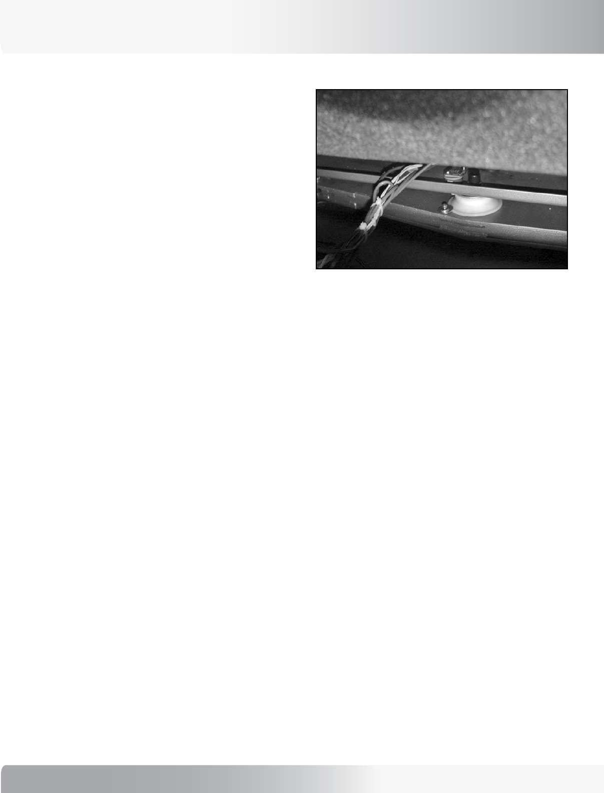
Check the Front Roller Snap Ring:
12-6: Verify that the snap ring on the front rollers is in place
properly (see Figure 2).
NOTE: This can be seen more easily with the treadle
guards removed.
Check the Rear Roller Pulley:
12-7: Check the rear roller pulley, if the pulley wobbles it
was pressed on incorrectly and the entire roller needs
to be replaced.
12-8:
Check the center of the rear roller (where the two
halves join) if there is any wobble the roller was not
assembled correctly and needs to be replaced.
MECHANICAL SERVICE

30
CARDIO CONSOLE CODES
General Information:
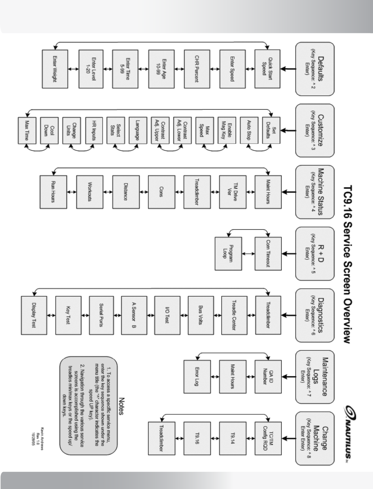
• Press the UP Speed/Load key [], the numeric [ # ] key, and then press the [ENTER] key once to enter this mode.
Pressing [] or [] forwards or backs up through the selections. Pressing [ENTER] then selects that item. Enter
values then press the [ENTER] key again to store the value.
• Once in console codes mode, pressing [] [] forwards or backs up through the selection, pressing [ENTER] then
selects that item. Pressing [CLEAR] exits any of the special access modes.
• Pressing [CLEAR] twice will exit the Console Service Mode.
Workout Default Console Codes:
[] [ 2 ] [ ENTER ] “DEFAULTS”
[] [ ENTER ] “ENTER WT XXX”
[] [ ENTER ] “ENTER LEVEL 1 TO 20”
[] [ ENTER ] “ENTER TIME 5 TO 99”
[] [ ENTER ] “ENTER AGE 10 TO 99”
[] [ ENTER ] “CHR PERCENT XX”
[] [ ENTER ] “ENTER SPEED XX.X”
[] [ ENTER ] “QUICK SPEED XX.X”
[] [ 3 ] [ ENTER ] “CUSTOMIZE”
[] [ ENTER ] “MAX TIME”
[] [ ENTER ] “COOL DOWN”
[] [ ENTER ] “CHANGE UNITS”
[] [ ENTER ] “HR INPUTS”
[] [ ENTER ] “SELECT STATS”
[] [ ENTER ] “LANGUAGE”
[] [ ENTER ] “UPPER CONTRAST ADJ”
[] [ ENTER ] “LOWER CONTRAST ADJ”
[] [ ENTER ] “MAX SPEED”
[] [ ENTER ] “ENABLE MAG KEY”
[] [ ENTER ] “AUTO STOP”
[] [ ENTER ] “SET DEFAULTS“
[] [ 4 ] [ ENTER ] “MACHINE STATUS”
[] [ ENTER] “ RUN HOURS”
[] [ ENTER ] “ WORKOUTS”
[] [ ENTER ] “ DISTANCE”
[] [ ENTER ] “ CONSOLE VERSION” “Displays Console Version #”
[] [ ENTER ] “DEVICE TYPE” ”Displays Machine Type”
[] [ ENTER ] “ TM DRIVE VER”
[] [ ENTER ] “ MAINT HOURS”
NOTE: SEVERAL CODES MAY BE INCLUDED IN THE
CONSOLE CODES LIST THAT DO NOT APPLY
TO THE TREADCLIMBER® FUNCTIONS.

31
Nautilus® TreadClimber®, Model TC916 Service Manual
CARDIO CONSOLE CODES
Workout Default Console Codes Continued…
[] [ 5 ] [ ENTER ] “ R AND D”
[] [ENTER] “ PROGRAM LOOP”
[] [ENTER] “ COM TIMEOUT”
[] [ 6 ] [ ENTER ] “ DIAGNOSTIC ”
[] [ ENTER ] “DISPLAY TEST”
[] [ ENTER ] “KEY TEST”
[] [ ENTER ] “SERIAL PORTS”
[] [ ENTER ] “A SENSOR B”
[] [ ENTER ] “I/O TEST”
[] [ ENTER ] “BUS VOLTS”
[] [ ENTER ] “TREADLE CENTER”
[] [ ENTER ] “TREADCLIMBER”
[] [ 7 ] [ ENTER ] “ MAINTENANCE LOGS ”
[] [ ENTER ] “ERROR LOG”
[] [ ENTER ] “MAINT HOURS”
[] [ ENTER ] “QA ID”
[] [ 8 ] [ ENTER ] “ CHANGE MACHINE” [ ENTER ]
For Treadmill Devices, the selections are:
[] [ ENTER ] “TREADCLIMBER”
[] [ ENTER ] “T916”
[] [ ENTER ] “T914”
[] [ ENTER ] “TC/TM CONFIG RQD”
32
CARDIO CONSOLE CODES
33
Nautilus® TreadClimber®, Model TC916 Service Manual
PARTS LIST
ORDERING REPLACEMENT PARTS:
In the US, call 800-628-8458. Outside the US, call +44-26-460-77-77. Authorized Nautilus representitives will assist you
with your specific service requirements. Items in the parts list highlighted in gray are replaceable. Items with no warranty
code or part number are replaceable as part of a higher-level assembly only.
WARRANTY NOTES (FOR UNITS IN THE USA ONLY):
1 — Part covered under standard 3 year parts warranty for replacement.
2 — Part covered under standard 1 year wear item warranty for replacement.
3 — Part covered under standard 15 year frame and AC-motor warranty.
International warranty coverage may vary. Contact an International office listed in the Important Contact Number section of
this manual for information.
REF #: ASSEMBLY #: PART #: DESCRIPTION: WARRANTY:
SM17501 ASSEMBLY, REAR ROLLER 3 YEAR
10 SM17568 Weldment, Base Frame 15 YEAR
25 SM17570 Spacer, Treadle Heim Joint 3 YEAR
141 SM17591 Weldment, Rear Step 15 YEAR
26 SM17615 Washer, Shoulder Isolation 3 YEAR
28 SM17617 ASSEMBLY, TREADLE — RIGHT SIDE
29 SM17508 Assembly, Front Roller 3 YEAR
69 SM17522 Weldment, Right Treadle 15 YEAR
70 SM17526 Weldment, Belt Tensioner 15 YEAR
34 SM17528 Spacer, Rear Bearing 3 YEAR
72 SM17543 Weldment, Cylinder Mount 15 YEAR
106 SM17578 Washer, Lock, Int. Star #10, SS 3 YEAR
255 SM17579 Screw, FH, 10-32 x .75, Hex Dr. SS 3 YEAR
77 SM17608 Weldment, Treadle Guard, Right 15 YEAR
38 SM17609 Casting, Treadle Front Roller Mount 3 YEAR
75 SM17618 Cover, Front Slide 3 YEAR
40 SM17620 Plate, Deck Support 3 YEAR
41 SM17660 Casting, Cover, Right Treadle Pivot 3 YEAR
42 SM17664 Cover, Bottom Treadle Right 1 YEAR
43 SM17666 Cover, Top Treadle Right 1 YEAR
44 SM17673 Block, Treadle End Cap 3 YEAR
242 SM17675 Screw, 1/4-20, x .75, Socket Head Cap 3 YEAR
46 SM17676 Screw, 3/8-24 x 2.00, Socket Head Cap 3 YEAR
47 SM17677 Screw, .500-13 x 4.00, Socket Head Cap 3 YEAR
48 SM17678 Screw, 3/8-24 x 1.50, Socket Head Cap 3 YEAR
68 SM17680 Screw, 3/8-16 1.25, Socket Head Cap 3 YEAR
174 SM17685 Key, 0.190 x 0.190x 1.380 3 YEAR
51 SM17691 Bearing, Ball 30MM x 55MM 3 YEAR
91 SM17692 Snap Ring, External, 25MM Dia. 3 YEAR
73 SM17865 Belt Guide, Aluminum
55 SM17731 Treadle Step, Right, Insert Molded 1 YEAR
34
PARTS LIST
REF #: ASSEMBLY #: PART #: DESCRIPTION: WARRANTY:
98 SM17808 Screw, 10-32 x .375, SHCS, SS 3 YEAR
63 SM17809 Screw, 10-32 x .625, SHCS SS 3 YEAR
173 SM17815 Screw, Button HD Cap, 10-32 x 5 /8L 3 YEAR
68 SM17860 Belt, Treadclimber 1 YEAR
30 SM17862 Deck, Treadle 1 YEAR
228 SM22047 Washer, Flat 1/4 ID x 5/8 OD 3 YEAR
90 SM22098 Screw, .250-20 x 1.50, Hex Head Cap 3 YEAR
58 SM22276 Screw, #6 S.T. x .625 Hex OR TO 3 YEAR
254 SM25777 Screw, .250-20 x 1.00 Button Head 3 YEAR
88 SM27585 Washer, .406 x .812 x .065 Flat 3 YEAR
65 SM17623 ASSEMBLY, TREADLE LEFT 3 YEAR
29 SM17508 Assembly, Front Roller 3 YEAR
32 SM17523 Weldment, Left Treadle 15 YEAR
70 SM17526 Weldment, Belt Tensioner 15 YEAR
34 SM17528 Spacer, Rear Bearing 3 YEAR
72 SM17543 Weldment, Cylinder Mount 15 YEAR
106 SM17578 Washer, Lock, Int. Star #10, SS 3 YEAR
255 SM17579 Screw, FH, 10-32 x .75, Hex Dr. SS 3 YEAR
38 SM17609 Casting, Treadle Front Roller Mount 3 YEAR
75 SM17618 Cover, Front Slide 3 YEAR
40 SM17620 Plate, Deck Support 3 YEAR
37 SM17625 Weldment, Left Treadle Guard 15 YEAR
78 SM17661 Casting, Cover, Left Treadle Pivot 3 YEAR
79 SM17665 Cover, Bottom Treadle Left 1 YEAR
80 SM17667 Cover, Top Treadle Left 1 YEAR
44 SM17673 Block, Treadle End Cap 3 YEAR
242 SM17675 Screw, 1/4-20, x .75, Socket Head Cap 3 YEAR
46 SM17676 Screw, 3/8-24 x 2.00, Socket Head Cap 3 YEAR
47 SM17677 Screw, .500-13 x 4.00, Socket Head Cap 3 YEAR
48 SM17678 Screw, 3/8-24 x 1.50, Socket Head Cap 3 YEAR
68 SM17680 Screw, 3/8-16 1.25, Socket Head Cap 3 YEAR
73 SM17685 Guide, Belt 3 YEAR
51 SM17691 Bearing, Ball 30MM x 55MM 3 YEAR
91 SM17692 Snap Ring, External, 25MM Dia. 3 YEAR
101 SM17732 Treadle Step, Left, Insert Molded 1 YEAR
98 SM17808 Screw, 10-32 x .375, SHCS, SS 3 YEAR
63 SM17809 Screw, 10-32 x .625, SHCS SS 3 YEAR
173 SM17815 Screw, Button HD Cap, 10-32 x 5 /8L 3 YEAR
68 SM17860 Belt, Treadclimber 1 YEAR
30 SM17862 Deck, Treadle 1 YEAR
228 SM22047 Washer, Flat 1/4 ID x 5/8 OD 3 YEAR
90 SM22098 Screw, .250-20 x 1.50, Hex Head Cap 3 YEAR
35
Nautilus® TreadClimber®, Model TC916 Service Manual
PARTS LIST
REF #: ASSEMBLY #: PART #: DESCRIPTION: WARRANTY:
58 SM22276 Screw, #6 S.T. x .625 Hex OR TO 3 YEAR
254 SM25777 Screw, .250-20 x 1.00 Button Head 3 YEAR
88 SM27585 Washer, .406 x .812 x .065 Flat 3 YEAR
SM17626 ASSEMBLY, UPRIGHT
110 SM17702 Housing, Ergo, CHR, Top Left 1 YEAR
111 SM17703 Housing, Ergo, Bottom Left 1 YEAR
112 SM17704 Housing, Ergo, CHR, Top Right 1 YEAR
113 SM17705 Housing, Ergo, Bottom Right 1 YEAR
114 SM17739 Keypanel, Ergo, TC916 1 YEAR
256 SM40639 Screw, 6-32 x .438 Lg Shc 3 YEAR
121 SM41034 Contact Plate, CHR 1 YEAR
122 SM41112 Housing, Ergo, Bottom Center 1 YEAR
123 SM41158 End Cap, Handle Barm Molded 1 YEAR
SM41169 Cable Harness 3 YEAR
SM41180 Heart Rate Detection Module 3 YEAR
SM41193 Cable Harness 3 YEAR
257 SM41268 Screw, 6-32 x .3125, SHCS 3 YEAR
SM41443 Cable Harness 3 YEAR
102 SM17793 Assy, Weldment, Upper Right
252 SM17794 Assy, Weldment, Lower Right
N/A SM17824 Assy, Harness Extension, Console
N/A SM17826 Assy, Harness, Extension, VSD
N/A SM17775-007 Intrnl/Extrnl Washer .375
N/A SM25796 Screw, .375-16 x 1.00, BH, SS
SM41449 Assy, Ergo Bar, Touch Sensor 1 YEAR
27 SM17631 Belt, Drive, Poly-V 3 YEAR
SM17640 ASSEMBLY, TREADLE DEPENDENCY
129 SM17551 Weldment, Treadle Rocker 15 YEAR
135 SM41048 Bearing, Ball, 25MM x 52MM 3 YEAR
130 SM17639 Shaft, Rocker Pivot 3 YEAR
52 SM17692 Snap Ring, External, 25MM Dia 3 YEAR
128 SM17548 Gear, 120T (48DP), Cut 3 YEAR
251 SM17742 Bracket, Gear Locking 3 YEAR
250 SM24088 Washer, #10 Split Lock 3 YEAR
136 SM17641 ASSEMBLY, DEPENDENCY LINK
146 SM17651 Bumper, Rubber Stop 3 YEAR
147 SM17652 Cover, Front Trim 1 YEAR
148 SM17653 Cover, Right Pan 1 YEAR
149 SM17654 Cover, Left Pan 1 YEAR
150 SM17655 Cover, Right Side 1 YEAR
151 SM17656 Cover, Left Side 1 YEAR
152 SM17657 Cover, Right Pivot 1 YEAR
36
PARTS LIST
REF #: ASSEMBLY #: PART #: DESCRIPTION: WARRANTY:
153 SM17658 Cover, Left Pivot 1 YEAR
154 SM17659 Cover, Lower Front Step 1 YEAR
107 SM17668 Cover, Top Upright Right 1 YEAR
108 SM17669 Cover, Top Upright Left 1 YEAR
155 SM17670 ASSEMBLY, CONSOLE TC916 3 YEAR
46 SM17676 Screw, 3/8-24 x 2.00, SHC 3 YEAR
177 SM17682 Screw, 3/8-16 x 1.00 Button Head Cap 3 YEAR
172 SM17683 Screw, .500-13 x 3.25, Hex Head Cap 3 YEAR
175 SM17686 Leveler, 0.500 inches-13 x 0.875 Tall 3 YEAR
178 SM17688 ASSMEBLY, VSD, TC9.16 3 YEAR
260 — INT SM41404 Assembly, Choke, 6MH, International Units
253 SM17689 Decal, Step Warning 1 YEAR
258 SM17695 Screw, #10-32 x 0.375, Flat Head, Phil 3 YEAR
188 SM17719 ASSEMBLY, CONFIG PLATE, TC9 SERIES (USA Domestic Units) 3 YEAR
188 — INT SM17823 Assembly, Config Plate, 230V, International Units TC9
63 SM28214 Screw, 10-32 x .750 Socket HDCP
125 SM17569 Assy., Treadle Mount
143 SM17733 Rear Step, Insert Molded 1 YEAR
63 SM17809 Screw, 10-32 x .625, SHCS, SS 3 YEAR
126 SM17810 ASSMEBLY, CYLINDER, HYD. CONTROL, TC916
173 SM17815 Screw, Button Hd Cap, 10-32 x 5/8L 3 YEAR
233 SM22030 Washer, 3/8 USS Flat 3 YEAR
228 SM22047 Washer, Flat 1/4 ID x 5/8 OD 3 YEAR
132 SM22091 Washer, .50 SAE Flat 3 YEAR
133 SM22222 Washer, Split Lock, .50 3 YEAR
138 SM22893 Nut, Jam, .500-13 UNC, Grade 8 3 YEAR
230 SM24643 Nut, .375-16, HX Jam, Nylon Insert 3 YEAR
237 SM27487 Drive Motor, AC Variable 15 YEAR
238 SM27562 Washer, Neoprene, .490×1.063x.09 3 YEAR
239 SM27577 Screw, M6 x 1.00 x 16 HHCAP 3 YEAR
240 SM27578 Washer, M6, Splitlock, Zinc 3 YEAR
241 SM27579 Washer, M6, Flat, Zinc 3 YEAR
226 SM27586 Spacer, Nylon, .125x .500 x 1.120 3 YEAR
SM40837 Assembly, Rotary Encoder 3 YEAR
8 SM41059 Flywheel, Cast, NTR 6000/7000 3 YEAR
9 SM17545 Assembly, Position Sensor TC
134 SM25412 Screw, .500-13 x 1.75 Hex HD CA
212 SM17737 Decal, Siderail, Right
210 SM17740 Decal, Rear Pivot
209 SM17736 Decal, Rear Hood
211 SM17738 Decal, Siderail, Left
37
Nautilus® TreadClimber®, Model TC916 Service Manual
EXPLODED VIEWS
WORKING WITH EXPLODED VIEWS
The reference numbers in the drawings on the following pages correlate to the reference numbers in the parts list on the
preceding pages.
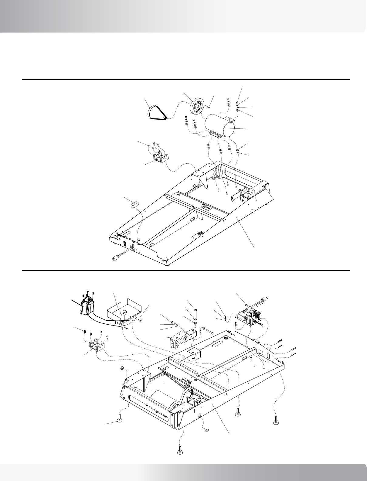
Base Frame with VSD Motor Control Board:
Base Frame with Drive Motor:
8
27
174
230
233
226
238
238
26
177
125
146
10
237
260
38
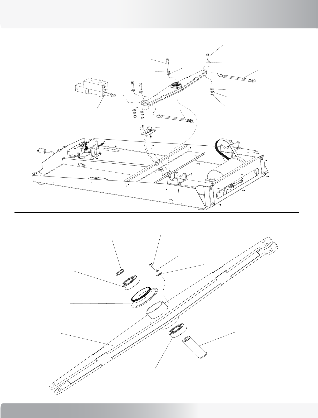
EXPLODED VIEWS
Base Frame with Dependency Link and Hydraulic System:
Dependency Link:
39
Nautilus® TreadClimber®, Model TC916 Service Manual
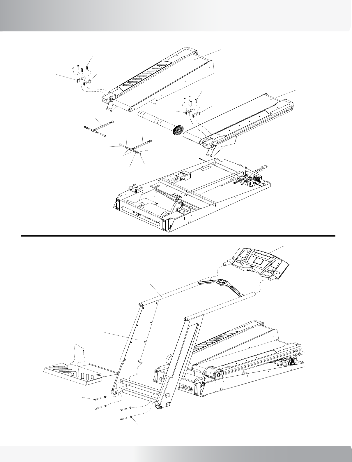
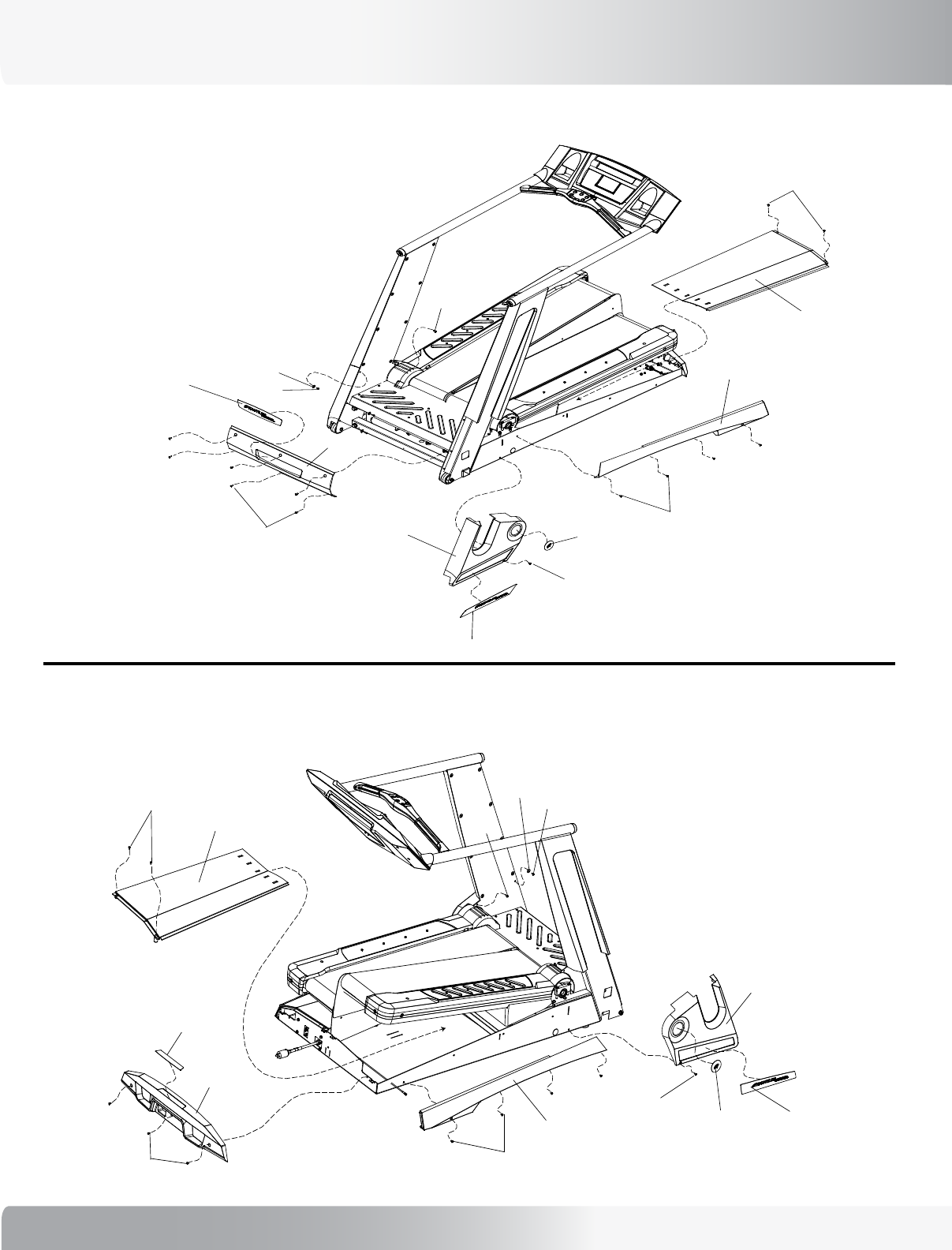
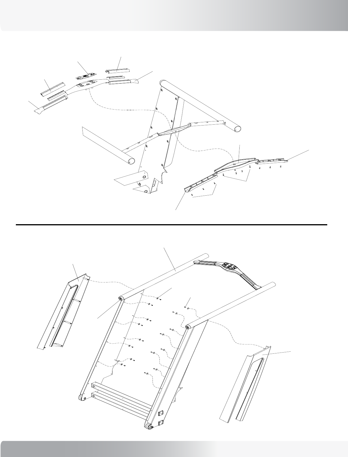
EXPLODED VIEWS
Console Upright Assembly, Rear Step and Console Assembly:
Treadle Assembly:
40
EXPLODED VIEWS
Base Frame Covers: (Right side as you stand on unit facing console.)
Base Frame Covers: (Left side as you stand on unit facing console.)
41
Nautilus® TreadClimber®, Model TC916 Service Manual
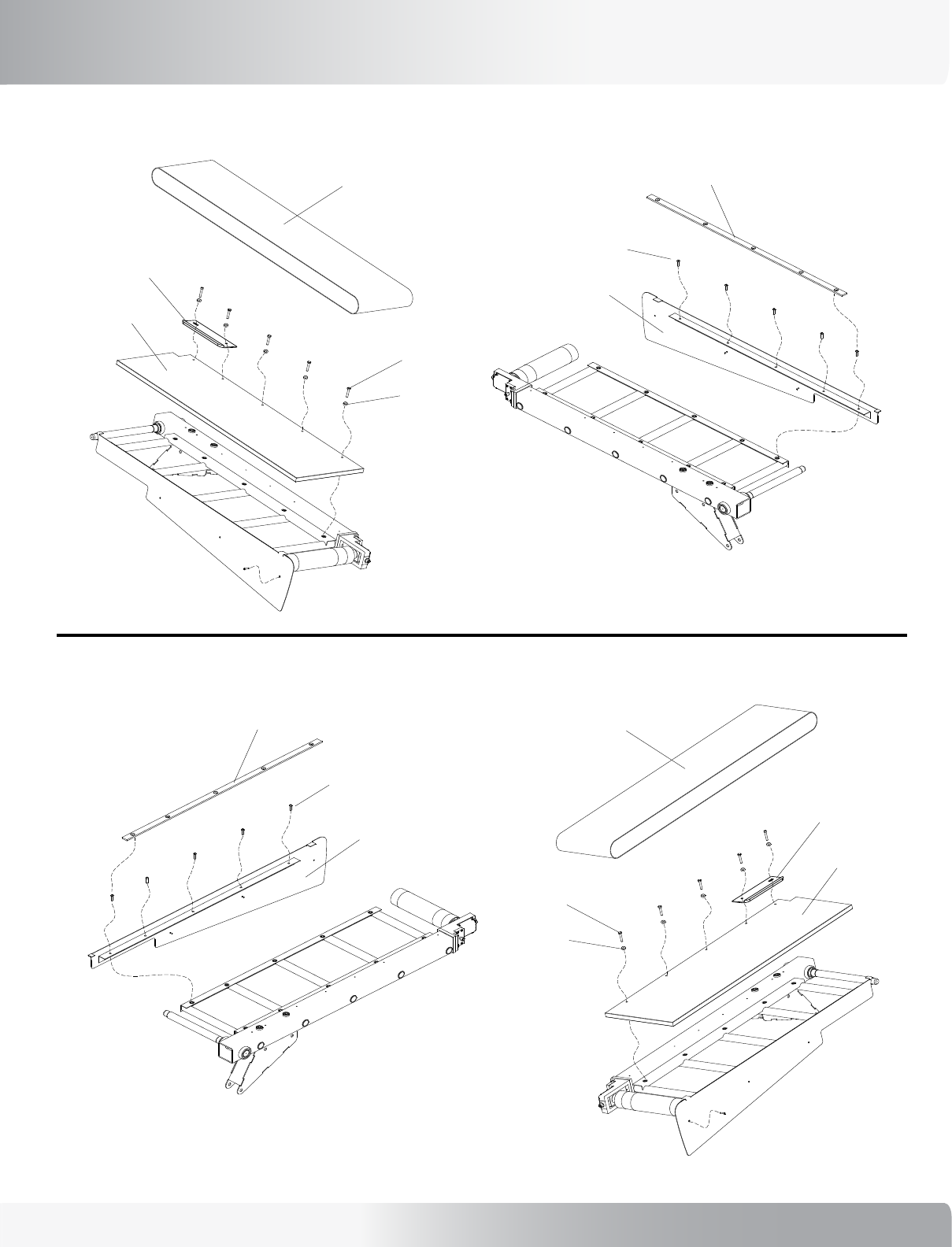
EXPLODED VIEWS
Treadle Deck and Belt Assembly: (Left side as you stand on unit facing console.)
Treadle Deck and Belt Assembly: (Right side as you stand on unit facing console.)
42
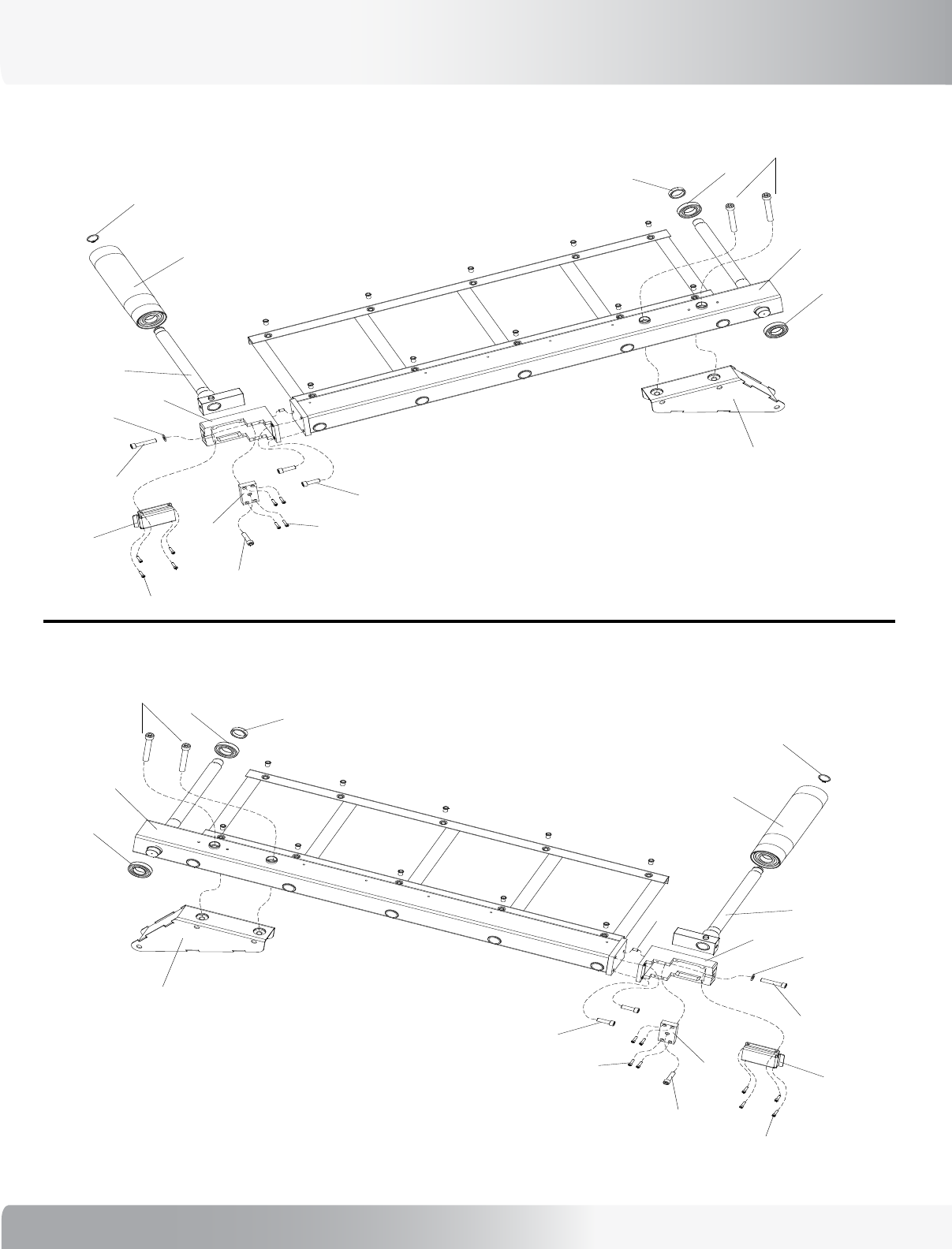
EXPLODED VIEWS
Treadle Arm Assembly: (Right side as you stand on unit facing console.)
Treadle Arm Assembly: (Left side as you stand on unit facing console.)
43
Nautilus® TreadClimber®, Model TC916 Service Manual
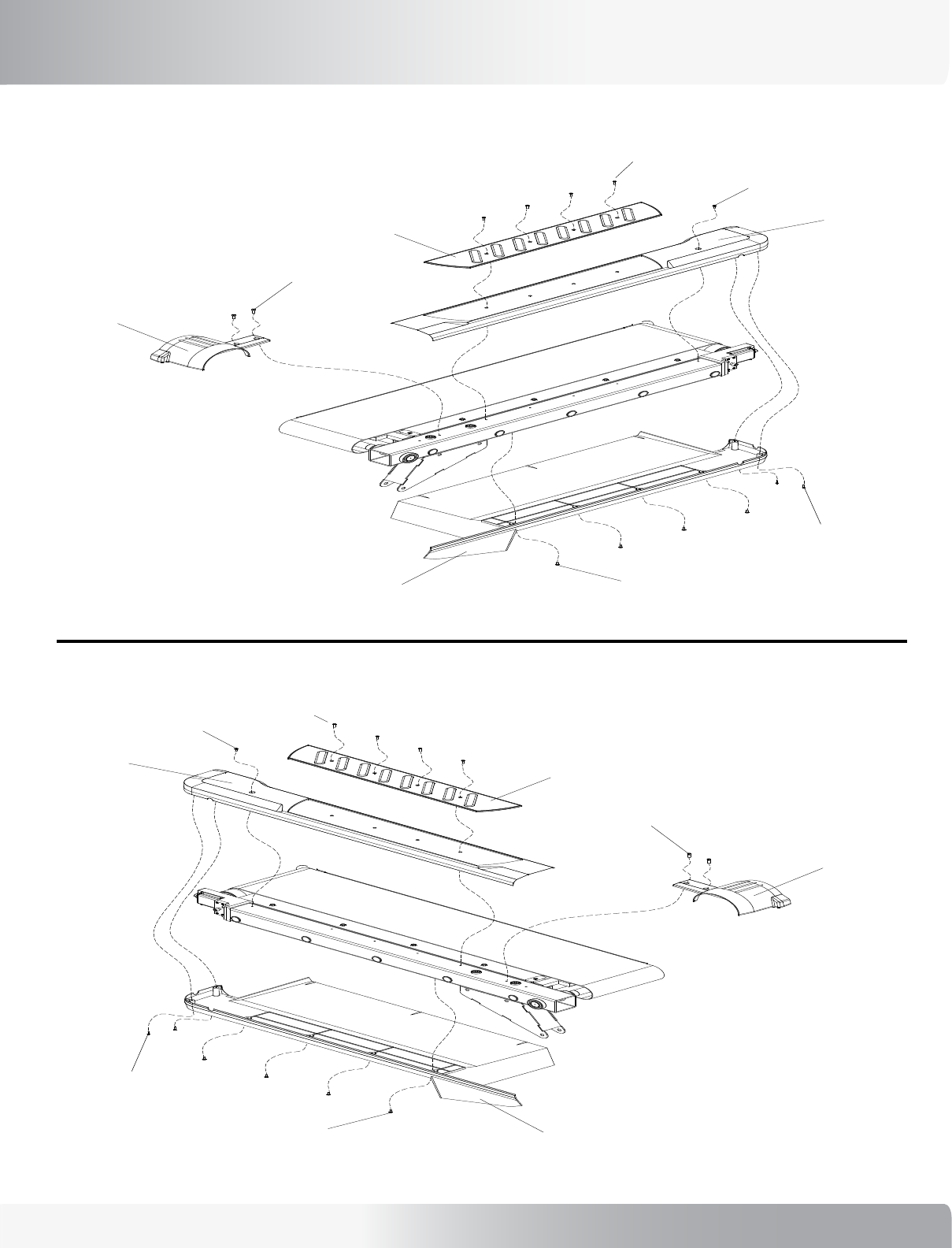
EXPLODED VIEWS
Treadle Covers — Top and Bottom: (Left side as you stand on unit facing console.)
Treadle Covers — Top and Bottom: (Right side as you stand on unit facing console.)
44
EXPLODED VIEWS
ROC Bar Assembly:
Console Upright and Cover Assembly:
45
Nautilus® TreadClimber®, Model TC916 Service Manual
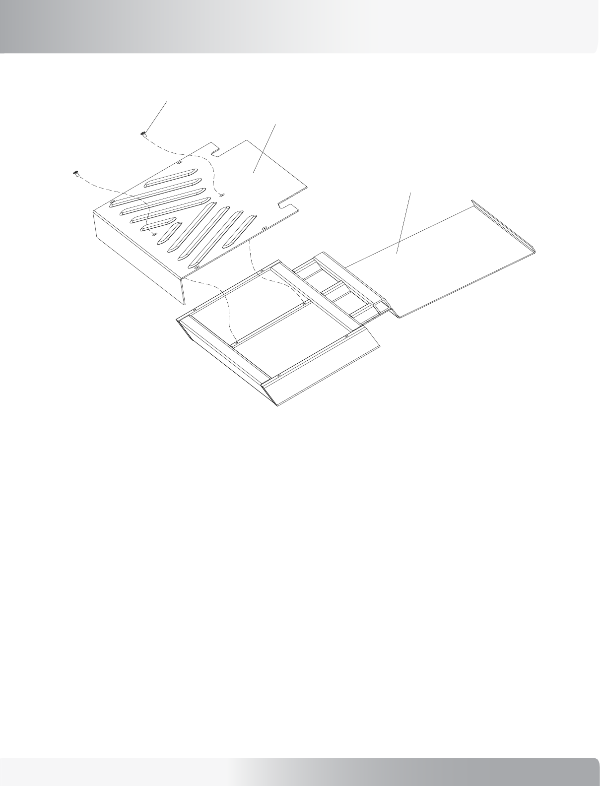
EXPLODED VIEWS
Rear Step and Support Platform:
46
ELECTRONIC TROUBLESHOOTING SUMMARY
1. LED
Operation on
PCBAs
What this means First Action Second Action Third Action Fourth Action
Note about use of Status LEDs: A single LED does not show the complete picture of an error condition. Review the status of all LEDs prior to deciding which assemblies
to replace.
P51 Processor PCBA:
DS1 Flashing @ 1
Second Rate
Normal Condition. Normal condition, no action required.
DS1 Flashing @
Irregular Rate
P51 Processor PCBA Non-
operational.
Power off/on treadmill, see if problem self-
clears. Check for unplugged or damaged
cables. Communication cable from J10 on
P51 Processor PCBA is cable most likely to
cause problem.
Replace P51
Processor PCBA.
DS1 Off Processor is non-operational.
No power or P51 Processor
PCBA has failed.
Power off/on treadmill, see if problem self-
clears. Check for unplugged or damaged
cables. Communication cable from J10 on
P51 Processor PCBA is cable most likely to
cause problem.
Check LEDs on VSD
to see if VSD has
power.
Replace P51
Processor PCBA.
DS1 On Continuous P51 Processor PCBA Non-
operational.
Power off/on treadmill, see if problem self-
clears.
Replace P51
Processor PCBA.
VSD PCBA:
DS1 Flashing @ Any
Rate
VSD PCBA is Non-operational. Power off/on treadmill, see if problem self-
clears. Check for unplugged or damaged
cables. Communication cable from J10 on
P51 Processor PCBA is cable most likely to
cause problem.
Replace VSD
PCBA.
DS1 Off Walkbelt motor is OFF. Normal condition, no action required.
DS1 On Continuous Walkbelt motor is ON. Normal condition, no action required.
DS2 Flashing @ 1
Second Rate
Normal condition. Normal condition, no action required.
DS2 Flashing @
Irregular Rate
Processor in reset is
attempting to re-establish
communication.
Power off/on treadmill, see if problem self-
clears. Check for unplugged or damaged
cables. Communication cable from J10 on
P51 Processor PCBA is cable most likely to
cause problem.
Replace VSD
PCBA.
Replace
Configuration
Plate.
DS2 Off Processor in reset or no
communication.
Power off/on treadmill, see if problem self-
clears. Check for unplugged or damaged
cables. Communication cable from J10 on
P51 Processor PCBA is cable most likely to
cause problem.
Replace VSD
PCBA.
Replace P51
Processor PCBA.
Replace Configuration
Plate.
47
Nautilus® TreadClimber®, Model TC916 Service Manual
ELECTRONIC TROUBLESHOOTING SUMMARY
1. LED
Operation on
PCBAs
What this means First Action Second Action Third Action Fourth Action
DS2 On Continuous Walkbelt Over current
Condition.
This error is usually caused by excessive
drag or friction on the deck. Closely inspect
the deck and look for signs of excessive
wear. If needed replace the belt and deck.
Power off/on
treadmill, see
if problem self-
clears. Check
for unplugged or
damaged cables.
Replace VSD
PCBA.
Replace Drive Motor.
DS3 On Continuous 5V VCC Power Supply is
Operational.
Normal condition, no action required.
DS3 Off 5V VCC Power Supply is Non-
operational.
Check for unplugged or damaged cables.
Cable going to P14 on VSD PCBA is most
likely to cause problem.
Use an ohmmeter
to verify Config
PCBA fuses F3 and
F4.
Replace VSD
PCBA.
Replace Configuration
Plate.
DS4 On Continuous 15V Predrive Power Supply is
Operational.
Normal condition, no action required.
DS4 Off 15V Predrive Power Supply is
Non-operational.
Check for unplugged or damaged cables.
Cable going to P20 on VSD PCBA is most
likely to cause problem.
Use an ohmmeter
to verify Config
PCBA fuses F3 and
F4.
Replace VSD
PCBA.
Replace Configuration
Plate.
DS5 On Very Bright Danger! High Voltage Drive
Bus Voltage Present.
Normal powered up condition. Do not handle
VSD PCBA until LEDs go out after about 2
minutes.
DS5 Off High Voltage Drive Bus
Capacitors have Discharged.
High Voltage Drive Bus is discharged and
VSD PCBA is safe to handle.
DS6 On Very Bright Danger! High Voltage Drive
Bus Voltage Present.
Normal powered up condition. Do not handle
VSD PCBA until LEDs go out after about 2
minutes.
DS6 Off High Voltage Drive Bus
Capacitors have Discharged.
High Voltage Drive Bus is discharged and
VSD PCBA is safe to handle.
2. Self-Test
Error Codes What this means First Action Second Action Third Action Fourth Action
ALU Error
Program Error
Static RAM Error
Timer Error
Internally generated processor
error.
Power off/on treadmill, see if problem self-
clears.
Replace P51
Processor PCBA.
EEPROM Error Stored data such as user
preferences, total time, and
mileage has been corrupted.
Power off/on treadmill, see if problem self-
clears. Defaults and configuration data will
need to be entered again.
Replace P51
Processor PCBA.
48
1. LED
Operation on
PCBAs
What this means First Action Second Action Third Action Fourth Action
3. Operational
Error Codes What this means First Action Second Action Third Action Fourth Action
DRIVE ERROR Occurs when the VSD PCBA
detects too low or too high of
a voltage on the DC drive bus.
Verify input line voltage is within
specifications. Error indicates voltage is too
low or high.
Ensure all
cables from the
configuration plate
to the VSD PCBA
are connected.
Cable going to P20
on VSD PCBA is
most likely to cause
problem.
Replace VSD
PCBA.
Replace Configuration
Plate.
DRIVE PWR ERROR
Early versions of
software displayed
this error as “ABS
ERROR” or “POWER
LOSS ERROR”
Can occur during program
operation. Treadmill goes to
idle and stops quickly. This
Error can denote any of the
following:
1 — The DC bus that powers the
walkbelt is too low or high.
2 — The thermal switch on the
walkbelt motor is open due to
the motor overheating.
3 — The circuitry that measures
the walkbelt motor current has
failed.
Verify input line voltage is within
specifications. Error indicates voltage is too
low or high.
Let walkbelt motor
cool down and
cycle power. Motor
thermal switch may
open due to worn
belt and deck.
Ensure all
cables from the
configuration plate
to the VSD PCBA
are connected.
Cable going to
P20 on VSD PCBA
is most likely to
cause problem.
Replace VSD PCBA.
If problem persists
replace Configuration
Plate.
DRV RESET The processor on the VSD
PCBA cannot communicate
with the motor control IC on
the VSD PCBA.
Ensure all cables from the configuration plate
to the VSD PCBA are connected. Cable going
to P20 on VSD PCBA is most likely to cause
problem.
Replace VSD
PCBA.
GRD LIMIT ERROR Unit must be reconfigured as a
TreadClimber.
Press [CLEAR].
Go to Change Machine Mode (Speed
Increase, 8, Enter, Enter), then scroll to
“TreadClimber” using the Speed Increase and
Speed Decrease keys.
ELECTRONIC TROUBLESHOOTING SUMMARY
49
Nautilus® TreadClimber®, Model TC916 Service Manual
1. LED
Operation on
PCBAs
What this means First Action Second Action Third Action Fourth Action
GRD MOVE ERROR Unit must be reconfigured as a
TreadClimber.
Press [CLEAR].
Go to Change Machine Mode (Speed
Increase, 8, Enter, Enter), then scroll to
“TreadClimber” using the Speed Increase and
Speed Decrease keys.
MULTIPLE KEY Message appears during the
Service Test KEY TEST, if two
keys are held down simulta-
neously or if a key is pressed
while another key is stuck
closed.
If possible, press [CLEAR], then go to Diag-
nostic Mode (Speed Increase, 6, ENTER), then
scroll to “Key Test” using the Speed Increase
and Speed Decrease keys. Press each key to
identify which key is stuck.
If problem persists,
open rear console
access panel.
Disconnect main
keyboard cable
from Processor
board, and connect
an alternate
known-good key
panel. Determine
whether keys are
now operable.
If the alternate
key panel works,
replace the key
panel.
Disconnect ROC
key panel cable,
determine whether
problem persists.
If problem goes
away with ROC
(Ergo) key panel
disconnected,
check Ergo cable.
Plug alternate
Touchsensor key
panel and check
operation. Replace
either ROC cable
or key panel as
required.
Replace P51
Processor PCBA.
NOT DEFINED, then
DRIVE POWER
ERROR
Message appears when Pin
10 of the communication cable
between the P51 Processor
and VSD PCBAs are open.
Replace Communication cable which con-
nects J10 on P51 Processor PCBA on VSD
PCBA.
Replace VSD
PCBA.
Replace P51
Processor PCBA.
NTM CONFIG RQRD This error indicates that the
P51 Processor PCBA was
manufactured for a non-Tread-
mill product such as an ellipti-
cal, stepper or bike.
Replace P51 Processor with one manufac-
tured for use in Treadmills or TreadClimbers.
OUT CUR ERROR Walkbelt motor current is too
low.
Ensure motor is connected to VSD PCBA.
Cycle power and see if problem self-clears.
Replace VSD
PCBA.
Replace Drive
Motor.
SYS OVRLD ERROR Walkbelt motor current is too
high or walkbelt motor thermal
switch has opened due to a
motor overload.
This error is usually caused by excessive
drag or friction on the deck. Closely inspect
the deck and look for signs of excessive wear.
If needed replace the belt and deck.
Let walkbelt motor
cool down and
cycle power. Motor
thermal switch may
open due to worn
belt and deck.
Replace VSD
PCBA.
Replace Drive Motor.
3. Operational
Error Codes
What this means First Action Second Action Third Action Fourth Action
ELECTRONIC TROUBLESHOOTING SUMMARY
50
1. LED
Operation on
PCBAs
What this means First Action Second Action Third Action Fourth Action
TC/TM CONFIG
RQRD
Unit must be reconfigured
as either a Treadmill or
TreadClimber or VSD PCBA
has wrong jumper configura-
tion.
Press [CLEAR].
Go to Change Machine Mode (Speed In-
crease, 8, Enter, Enter), then scroll to appro-
priate configuration using the Speed Increase
and Speed Decrease keys, then press ENTER.
Ensure jumpers on
VSD are correct.
TreadClimbers
should have all
three jumpers in
place on PC0, PC3
and PC5.
TM COM ERROR Treadmill or TreadClimber
communications error. Means
P51 Processor PCBA can’t talk
serially to VSD PCBA.
Cycle power and see if problem self-clears. Replace
communication
cable between P51
Processor PCBA
and VSD PCBA.
Replace VSD
PCBA.
Replace P51
Processor PCBA.
3. Operational
Error Codes
What this means First Action Second Action Third Action Fourth Action
ELECTRONIC TROUBLESHOOTING SUMMARY

51
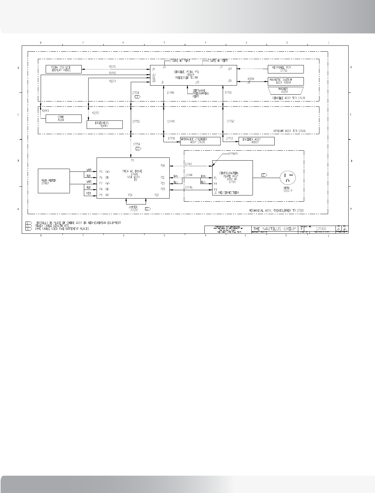
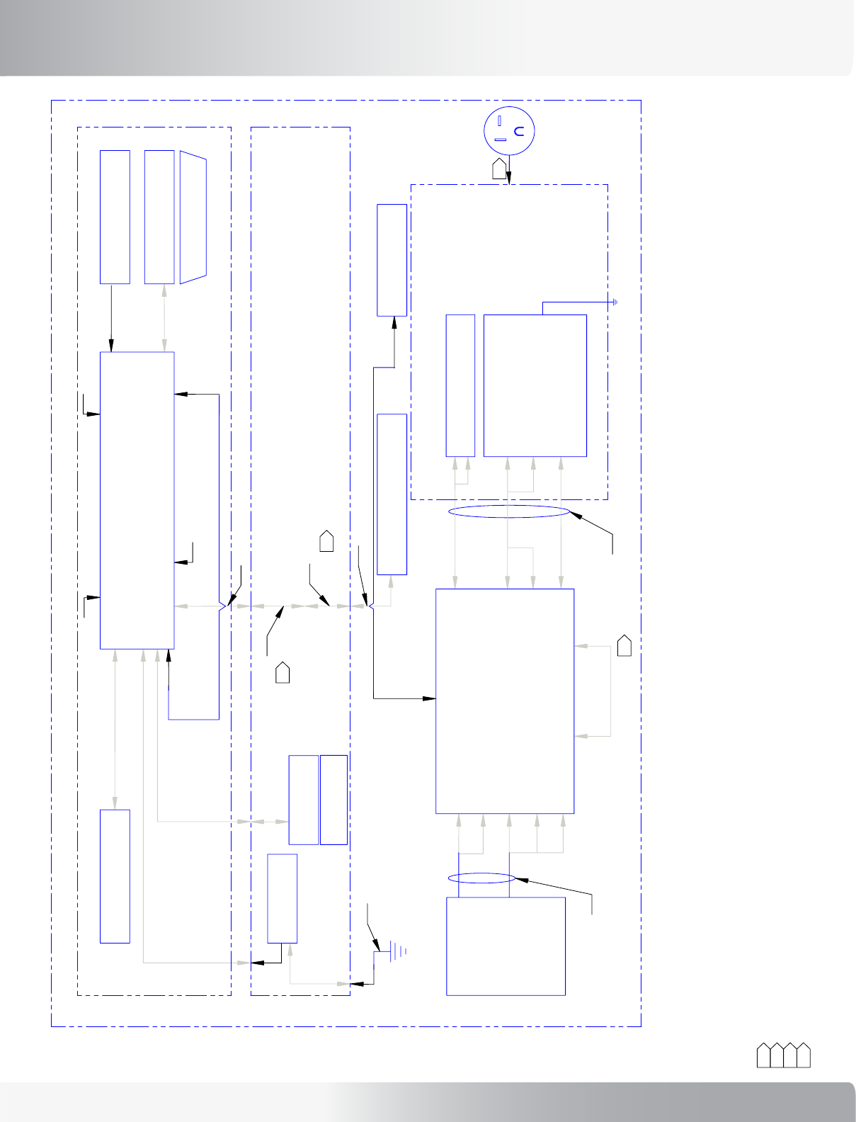
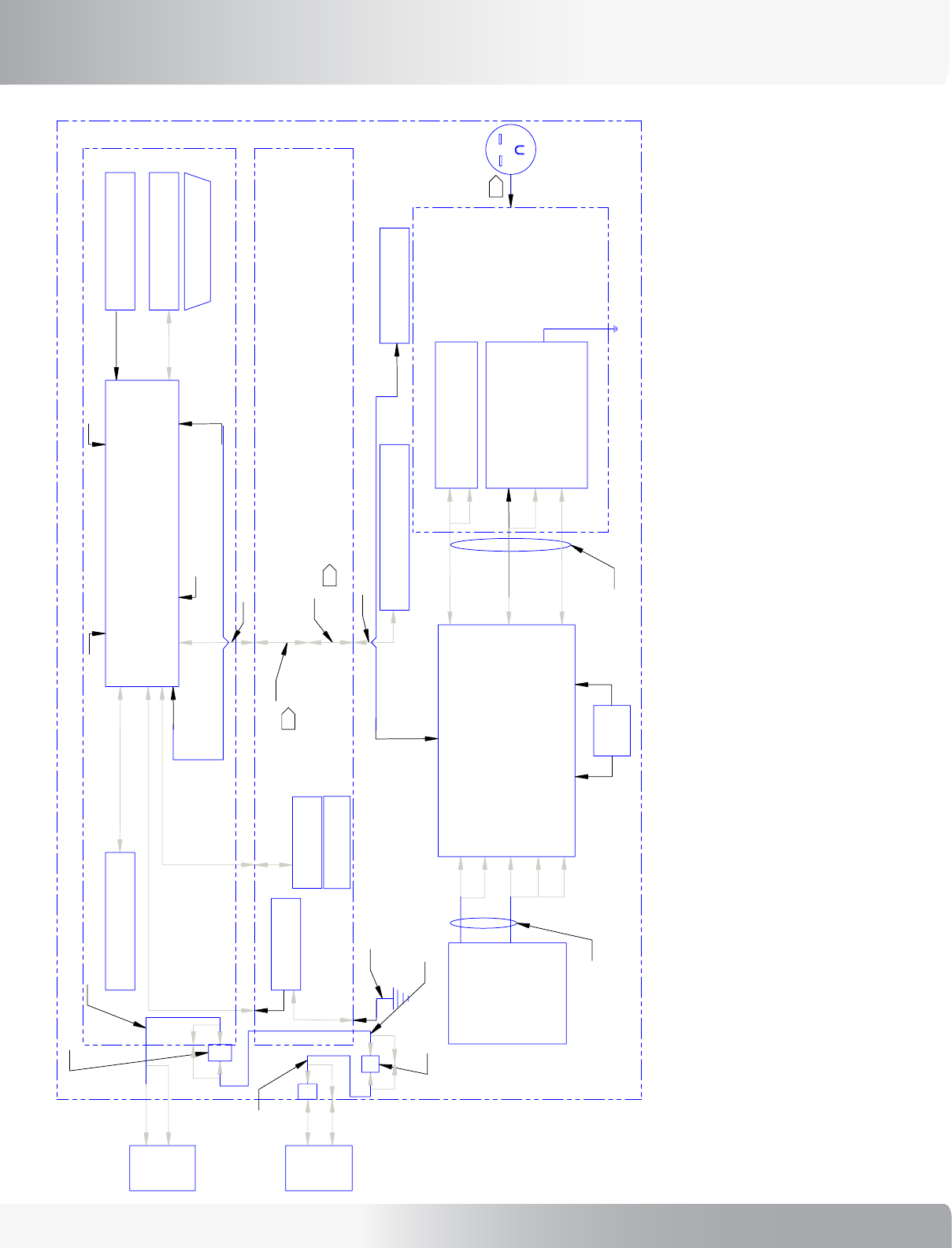
Nautilus® TreadClimber®, Model TC916 Service Manual
CABLE ASSY, T9 HR,
PROCESSOR SIDE
#41442
TC916
TREADCLIMBER
120V VERSIONS
TOP-LEVEL WIRING
T. BROWN 6/15/05
KEYBOARD
CSAFE #1 PORT
(TOP ENTRY)
CSAFE #2 PORT
T.C. TREADLE
POSITION SENSOR
SOFTWARE
PROGRAMMING
PORT
(TOP ENTRY)
T.C. PISTON
CONTROL
DISPLAY
(RIBBON CABLE TO
DISPLAY BOARD)
T.C. MOTOR CONTROL
BOARD INTERFACE
(SIDE ENTRY)
ERGO KEYS
REMOTE
CHR/WHR
MAGNET
CABLE ASSY
#41194
J16
J1
MAGNETIC
SWITCH
#40854
40824
PCBA, P51
PROCESSOR
TC/TM
CABLE ASSY
#41173
CABLE ASSY, FRONT ROC
#41193
CONFIGURATION
PLATE
ASSEMBLY
J3
J1
J2
LINE
FILTER
CIRCUIT
BREAKER
P2
P3
TRANSFORMER
(PART OF #27962)
CONFIG
PCBA
P1
P4
#27122
Installs in place of
choke assembly
on Non-European
treadmills.
35774-001 or
35774-002
#27319
17744
CABLE ASSY, T9 HR, HANDRAIL SIDE
#41443
#41175
#40865
PCBA, C52 LCD DISPLAY
CABLE ASSY
#41169
GREY
GREEN
RED
GREEN
#41008
TOUCH SENSOR
ASSY
CONTACT/
TELEMETRY HR
#41180
ROC BAR
ASSEMBLY
+
HYDRAULIC
CYLINDER
++
MAX
MIN
CENTER
TRAVEL
+
+
+
#40837
PCBA, ENCODER
POSITION SENSOR
#40825 ROTARY ENCODER
256 QUAD COUNT/REV
> 300 MILLION CYCLE LIFE
INDEX SENSOR
INDEX (ZERO-POINT)
LED INDICATOR
DEPENDENCY
MECHANISM
17746
17747
17748
17749
17750
17751
17752
17753
17754
17754
17755
TP9
+16V
P11
P15
U7
U8
U9
U10
U11
P5 P6
THERMAL
SWITCHES
P7 P8 P9
P20 P17 P18
P1
P3
P14
P19
2
1
10
9
1 10
9 8 7 4 3 1
4 3 2 1 2 1
P10
P12
P23
GRADE
SENSOR
RED
BLK
WHT
#41387
PCBA, AC DRIVE III
DS1 DS3
DS4
DS2
DS5
DS6
NOT SHOWN:
#27965
THERMAL TRANSFER
PAD (SILPAD)
#27571
PAD, VSD CLAMP
MAIN
MOTOR
#27487
F1
F2
F4
F3
32533-001
KEYPANEL:
#17716 TC916
WIRING SCHEMATIC
52
WIRING SCHEMATIC
53
Nautilus® TreadClimber®, Model TC916 Service Manual
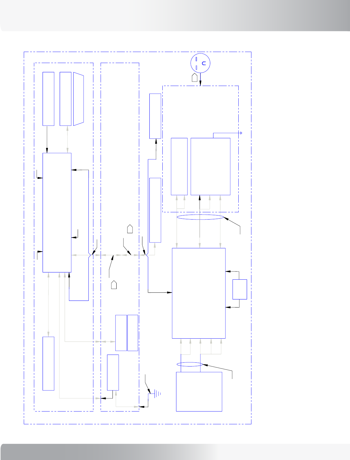
WIRING SCHEMATIC: 110 VAC DOMESTIC
27000
INSTALLS IN PLACE OF CHOKE ASSY ON NON-EUROPEAN EQUIPMENT
1.
POWER CABLE LENGTH 12FT.
2.
SAME TWO PLACES.
3.
POWER CORD IS COUNTRY SPECIFIC ON INTERNATIONAL MODEL
4.
MODEL ASSY, TREADCLIMBER T9 00200-001
BRN
BLU
BRN
BLU
YEL
YEL
WHT
BLK
RED
1
2
SOFTWARE
PROGRAMMING PORT
C’SAFE #1 PORT
C’SAFE #2 PORT
J1 J15 J2
J14
J16
J3 J7
J9
J17
J11
J10
CONSOLE ASSY TC9 17670
41193
41443
C3
C1
C2
JUMPER
27122
P1
17785
NEMA
5-20 P
PCB
P1
P4
J3
J1 (NO CONNECTION)
P14
P11
P15
P20
P5
P6
P7
P8
P9 P10 P12
PBCA AC DRIVE
17688
VSD ASSY
T9
MAIN MOTOR
27487
UPRIGHT ASSY TC9 17626
ENCODER ASSY
17545
HYDRAULIC CYLINDER
ASSY 17810
(C2)
(C1)
(C2)
(C1)
(C3)
CONSOLE, PCBA, P51
40824
PROCESSOR TC/TM
(C3)
41173
41442
41175
ERGO KEYS
41449
CTHR
41180
PCBA, C52 LCD
DISPLAY 40865
41194
MAGNET
41154
MAGNETIC SWITCH
ASSY 40854
KEYPANEL TC9
17716
OVERLAY
17739
17826
17778
17498
CONFIGURATION
PLATE ASSY
120V AC 17719
17786
17824
3
3
17824
TRANSFORMER
27964
7
12
54
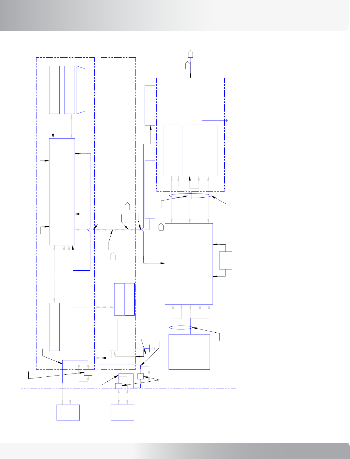
WIRING SCHEMATIC: 230 VAC DOMESTIC
17824
3
3
17824
17786
CONFIGURATION
PLATE ASSY
230V AC 17823
CHOKE
41404
17859
17778
17826
OVERLAY
17739
KEYPANEL TC9
17716
MAGNETIC SWITCH
ASSY 40854
MAGNET
41154
41194
PCBA, C52 LCD
DISPLAY 40865
CTHR
41180
ERGO KEYS
41449
41175
41442
41173
(C3)
CONSOLE, PCBA, P51
40824
PROCESSOR TC/TM
(C3)
(C1) (C2)
(C1) (C2)
HYDRAULIC CYLINDER
ASSY 17810
ENCODER ASSY
17545
UPRIGHT ASSY TC9 17626
MAIN MOTOR
27487
PBCA AC DRIVE
17688
VSD ASSY
T9
P5
P6
P7
P8
P9 P10 P12
P14
P19
P20
P1
P4
J3
J1 (NO CONNECTION)
PCB
17590
NEMA
6-15 P
P1
C2
C1
C3
41443 41193
CONSOLE ASSY TC9 17670
J9
J17
J11
J10
J3 J7
J14
J16
J1 J15 J2
C’SAFE #2 PORT C’SAFE #1 PORT
SOFTWARE
PROGRAMMING PORT
2
YEL
YEL
WHT
BLK
RED
BRN
BLU
MODEL ASSY, TREADCLIMBER T9 00200-002
27000
TRANSFORMER
27964
7
12
55
Nautilus® TreadClimber®, Model TC916 Service Manual
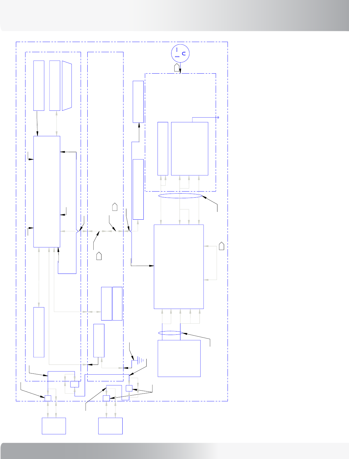
WIRING SCHEMATIC: 230 VAC INTERNATIONAL
17824
3
3
17824
17786
CONFIGURATION
PLATE ASSY
230V AC 17823
CHOKE
41404
17859
17778
17826
OVERLAY
17739
KEYPANEL TC9
17716
MAGNETIC SWITCH
ASSY 40854
MAGNET
41154
41194
PCBA, C52 LCD
DISPLAY 40865
CTHR
41180
ERGO KEYS
41449
41175
41442
41173
(C3)
CONSOLE, PCBA, P51
40824
PROCESSOR TC/TM
(C3)
(C1) (C2)
(C1) (C2)
HYDRAULIC CYLINDER
ASSY 17810
ENCODER ASSY
17545
UPRIGHT ASSY TC9 17626
MAIN MOTOR
27487
PBCA AC DRIVE
17688
VSD ASSY
T9
P5
P6
P7
P8
P9 P10 P12
P14
P19
P20
P1
P4
J3
J1 (NO CONNECTION)
PCB
P1
C2
C1
C3
41443 41193
CONSOLE ASSY TC9 17837 (17670)
J9
J17
J11
J10
J3 J7
J14
J16
J1 J15 J2
C’SAFE #2 PORT C’SAFE #1 PORT
SOFTWARE
PROGRAMMING PORT
2
YEL
YEL
WHT
BLK
RED
BRN
BLU
MODEL ASSY, TREADCLIMBER T9 00200-003
27000
4
TRANSFORMER
27964
7
12
41399
5
TV
TV IN
2X 17787
17787
17844
17845
17846
56
WIRING SCHEMATIC: 110 VAC DOMESTIC WITH TV
12
7
TRANSFORMER
27964
17824
3
3
17824
17786
CONFIGURATION
PLATE ASSY
120V AC 17719
17498
17778
17826
OVERLAY
17739
KEYPANEL TC9
17716
MAGNETIC SWITCH
ASSY 40854
MAGNET
41154
41194
PCBA, C52 LCD
DISPLAY 40865
CTHR
41180
ERGO KEYS
41449
41175
41442
41173
(C3)
CONSOLE, PCBA, P51
40824
PROCESSOR TC/TM
(C3)
(C1) (C2)
(C1) (C2)
HYDRAULIC CYLINDER
ASSY 17810
ENCODER ASSY
17545
UPRIGHT ASSY TC9 17626
MAIN MOTOR
27487
PBCA AC DRIVE
17688
VSD ASSY
T9
P5
P6
P7
P8
P9 P10 P12
P14
P11
P15
P20
P1
P4
J3
J1 (NO CONNECTION)
PCB
17785
NEMA
5-20 P
P1
JUMPER
27122
C2
C1
C3
41443 41193
CONSOLE ASSY TC9 17835 (17670)
J9
J17
J11
J10
J3 J7
J14
J16
J1 J15 J2
C’SAFE #2 PORT C’SAFE #1 PORT
SOFTWARE
PROGRAMMING PORT
2
1
YEL
YEL
WHT
BLK
RED
BRN
BLU
BRN
BLU
MODEL ASSY, TREADCLIMBER T9 00200-004
27000
TV IN
TV
17846
17787
2X 17787
17845
17844
57
Nautilus® TreadClimber®, Model TC916 Service Manual
WIRING SCHEMATIC: 230 VAC DOMESTIC WITH TV
12
7
TRANSFORMER
27964
27000
MODEL ASSY, TREADCLIMBER T9 00200-005
BRN
BLU
YEL
YEL
WHT
BLK
RED
2
SOFTWARE
PROGRAMMING PORT
C’SAFE #1 PORT
C’SAFE #2 PORT
J1 J15 J2
J14
J16
J3 J7
J9
J17
J11
J10
CONSOLE ASSY TC9 17835 (17670)
41193
41443
C3
C1
C2
P1
17590
NEMA
6-15P
PCB
P1
P4
J3
J1 (NO CONNECTION)
P14
P19
P20
P5
P6
P7
P8
P9 P10 P12
PBCA AC DRIVE
17688
VSD ASSY
T9
MAIN MOTOR
27487
UPRIGHT ASSY TC9 17626
ENCODER ASSY
17545
HYDRAULIC CYLINDER
ASSY 17810
(C2)
(C1)
(C2)
(C1)
(C3)
CONSOLE, PCBA, P51
40824
PROCESSOR TC/TM
(C3)
41173
41442
41175
ERGO KEYS
41449
CTHR
41180
PCBA, C52 LCD
DISPLAY 40865
41194
MAGNET
41154
MAGNETIC SWITCH
ASSY 40854
KEYPANEL TC9
17716
OVERLAY
17739
17826
17778
17859
CHOKE
41404
CONFIGURATION
PLATE ASSY
2300V AC 17823
17786
17824
3
3
17824
17846
17787
2X 17787
17845
17844
TV IN
TV

58
OFFICES IN THE UNITED STATES:
E-mail: cstech@nautilus.com
• NAUTILUS INNOVATION CENTER
Nautilus, Inc.
1886 Prairie Way
Louisville, Colorado, USA 80027
Vancouver, Washington, USA 98683
Phone: 800-NAUTILUS (800-628-8458)
Email: customerservice@nautilus.com
Fax: 800-898-9410
• TECHNICAL/CUSTOMER SERVICE
Nautilus, Inc.
World Headquarters
16400 SE Nautilus Drive
Vancouver, Washington, USA 98683
Phone: 800-NAUTILUS (800-628-8458)
Email: customerservice@nautilus.com
Fax: 877-686-6466
• CORPORATE HEADQUARTERS
Nautilus, Inc.
World Headquarters
16400 SE Nautilus Drive
Vancouver, Washington, USA 98683
Phone: 800-NAUTILUS (800-628-8458)
If you need assistance, please have both the serial number of your machine and the date of purchase available when you
contact the appropriate Nautilus office listed below.
INTERNATIONAL:
For technical assistance and a list of distributors
in your area, please call or fax one of the following
numbers.
• INTERNATIONAL CUSTOMER SERVICE
Nautilus International S.A.
Rue Jean Prouvé 6
1762 Givisiez / Switzerland
Tel: + 41-26-460-77-77
Fax: + 41-26-460-77-70
Email: technics@nautilus.com
BUSINESS OFFICES:
• SWITZERLAND OFFICE
Nautilus Switzerland S.A.
Tel: + 41-26-460-77-66
Fax: + 41-26-460-77-60
• GERMANY and AUSTRIA OFFICE
Nautilus GmbH
Tel: +49-2204-610-27
Fax: +49-2204-628-90
• ITALY OFFICE
Nautilus Italy s.r.l.
Tel: +39-031-51-10-86
Fax: +39-031-34-24-97
• UNITED KINGDOM OFFICE
Nautilus UK Ltd.
Tel: +44-1908-267-345
Fax: +44-1908-267-346
• CHINA OFFICE
Nautilus Representative Office
Tel: +86-21-523-707-00
Fax: +86-21-523-707-09
IMPORTANT CONTACT NUMBERS

59
Nautilus® TreadClimber®, Model TC916 Service Manual
PAGE INTENTIONALLY LEFT BLANK
©2006. Nautilus, Inc. All rights reserved. Nautilus, the Nautilus Logo, ROC, TreadClimber, StairMaster and Changing the Game in Health and Fitness
are either registered trademarks of trademarks of Nautilus, Inc. Polar and Fantastic are registered trademarks of their respective companies.
Nautilus, Inc. World Headquarters,
16400 SE Nautilus Drive, Vancouver, Washington, USA 98683
1-800-NAUTILUS www.nautilus.com
Model TC9.16
К огромному сожалению пользователей компьютеров под управлением ОС Windows различных версий, многим из них пришлось хоть раз столкнуться с проблемой в виде синего экрана смерти. Он же BSOD.
Причины синего экрана бывают разными. От безобидных, до более чем серьёзных, требующих вмешательства в техническую составляющую компьютерного устройства.

Одной из распространённых ошибок, которые сопровождаются синим экраном смерти, является «System thread exception not handled». Соответствующая надпись сопровождается цифро-буквенным кодом 00x1000007e, либо же 0x0000007E.
Необходимо понять, почему такая ошибка вообще может появляться, и что нужно сделать для её устранения. Многие из представленных советов можно вполне реализовать своими силами, не привлекая к работе специалистов и не затрачивая лишние деньги на их услуги.
Основные причины
Логично будет начать с причин появления кода остановки в виде подписи «System thread exception not handled» на экране ноутбука или стационарного компьютера. Подобная ошибка появляется на ОС Windows 10, но встречается и на более ранних версиях популярной операционной системы.

Причин появления ошибки достаточно много. Установить точно, почему именно пользователь столкнулся с подобной надписью на мониторе своего компьютера, порой возможно только методом исключения всех остальных потенциальных виновников.
С такой ошибкой юзер потенциально мог столкнуться по следующим причинам:
- произошёл случайный сбой компьютера или ноутбука;
- проблема находится со стороны нового подключаемого оборудования;
- всё дело в системных ошибках, которые придётся исправлять;
- нарушены корректные настройки в БИОСе;
- последствия неправильного или некорректного аппаратного ускорения;
- причина со стороны узла оперативной памяти;
- неполадки драйвера того или иного оборудования;
- поломки и дефекты комплектующих компьютерного устройства и пр.
В зависимости от того, что именно послужило причиной возникновения рассматриваемой ошибки, существуют соответствующие пути для их решения.
Каждую причину, как и рекомендации по её устранению, следует рассматривать отдельно.
СОВЕТ. Перед началом любых действий будет нелишним создать установочный диск с ОС Windows, если даже в безопасном режиме система запускаться не хочет. Либо же используйте безопасный режим или LiveCD.
Теперь последовательно о каждой из представленных причин, а также о действиях, необходимых для их устранения.
Произошёл случайный сбой
Достаточно часто с ошибкой «System thread exception not handled» пользователи сталкиваются именно в той ситуации, когда происходит случайный сбой системы. Этому удивляться не приходится, поскольку нет совершенной операционной системы. И периодически сбои не исключены.
Если это единичная акция, тогда особых проблем с устранением ошибки «System thread exception not handled» на компьютере возникнуть не должно. Единственное, что может потребоваться от юзера в такой ситуации, это на несколько минут полностью отключить от сети компьютерное устройство, после чего перезапустить его.
Когда код рассматриваемой ошибки «System thread exception not handled» всё равно остаётся на фоне синего экрана смерти, придётся прибегать к более серьёзным действиям. Зато так удалось исключить вариант случайного сбоя. Есть какая-то проблема, устранять которую придётся методом исключения. Лучше начинать от наиболее вероятных и легко устранимых, постепенно двигаясь к тяжёлым и серьёзным потенциальным неполадкам.
Новое оборудование
Нельзя исключать, что с ошибкой «System thread exception not handled» пользователь столкнулся именно после того, как было куплено и установлено новое оборудование. Потому в этой ситуации придётся подтвердить либо же опровергнуть эту теорию.
Для начала проверьте подключённое оборудование на предмет его работоспособности. Также убедитесь в совместимости используемых драйверов для подключённого принтера, сканера, мышки и иного девайса с используемой версией операционной системы.
Одним из вариантов устранения ошибки типа «System thread exception not handled» является временное отключение нового оборудования. Если это было сразу несколько девайсов, отключать лучше поочерёдно. Параллельно проверяйте, не восстановилась ли нормальная работа ПК.
Статистика вещь упрямая. Она показывает, что с синим экраном и надписью «System thread exception not handled» на синем фоне сталкиваются чаще остальных пользователи мышек и веб-камер производства Logitech. Вероятнее всего, причина, из-за которой появляется синий экран, заключается в несовместимости драйверов.

Компьютерные комплектующие от компании Logitech
Тут можно попробовать 2 основных варианта:
- Приобрести новые девайсы. Если есть такая возможность. Но сначала проверьте, действительно ли причина ошибки с подписью «System thread exception not handled» кроется именно в этом оборудовании. Для этого просто подключите аналогичные девайсы и проверьте, как поведёт себя компьютер с ними.
- Переустановить или обновить программное обеспечение. Если драйверы устанавливались с диска, лучше удалить их, зайти на официальный сайт разработчиков девайсов и загрузить свежее ПО оттуда. Затем перезагрузите операционную систему.
Какой из этих вариантов подходит пользователю, решать только ему. Но точно не стоит спешить с покупкой нового оборудования, не убедившись, что причина ошибки кроется именно в этом.
Наличие системных ошибок
Столкнуться с кодом остановки с надписью «System thread exception not handled» также можно и по другой причине. Здесь речь идёт про системные ошибки на компьютере.
Проверить ПК или ноутбук на наличие системных ошибок можно 2 способами:
- через «Мой компьютер»;
- с помощью командной строки.
В случае с командной строкой нужно запустить её от имени Администратора, и прописать команду sfc /scannow.
Альтернативным вариантом будет использование возможностей сканирования через «Мой компьютер». Для этого следует выполнить такие процедуры:
Бывает и так, что появляется сообщение о невозможности проверить накопитель. В этом случае нажмите на «Расписание проверки».
После этого компьютер отправляется на перезагрузку. Система будет проверяться на наличие ошибок через BIOS и параллельно их исправлять при наличии.
Сама проверка может занимать от нескольких минут до пары часов. Это напрямую связано с характеристиками и объёмом тестируемого накопителя.
Важно заметить, что оба варианта устранения системных ошибок работают только при выполненном входе в операционную систему. Потому в ситуациях, когда ОС не запускается, придётся задействовать установочный образ.
Сброс в BIOS
Также в некоторых случаях с кодом остановки, сопровождающегося ошибкой «System thread exception not handled», помогает выполненный сброс настроек в BIOS.
Это одна из вероятных причин появления синего экрана. Причём необязательно вносить изменения в БИОС своими руками, чтобы произошла ошибка. Иногда это происходит автоматически в результате произошедшего сбоя.
Чтобы сбросить настройки, потребуется действовать согласно следующей инструкции:
- войти в сам БИОС;
- найти раздел, который отвечает за сброс текущих настроек, в основном он именуется как Optimized Defaults;
- кликнуть по этому разделу;
- подтвердить своё намерение сброса нажатием на кнопку «Yes»;

- сохранить внесённые изменения;
- перезагрузить компьютерное устройство.

Если причина крылась в этом, тогда после перезагрузки операционной системы всё должно нормально работать.
Если и этот шаг ни к чему не привёл, тогда следует пробовать следующий метод.
Аппаратное ускорение
Когда подобная ошибка происходит в процессе работы одной из версий операционной системы Windows 10, есть высокая вероятность, что причина кроется в аппаратном ускорении. Оно включено, и это ведёт к соответствующим проблемам.
Если виновником выступает аппаратное ускорение, тогда просто отключаем его, и всё должно нормализоваться.
На примере наиболее популярного браузера Chrome процесс отключения выглядит следующим образом:
- откройте панель настроек;
- листайте список меню практически до самого конца;
- внизу найдите пункт «Дополнительные»;
- найдите здесь опцию аппаратного ускорения;
- отключите её;

- сохраните изменения;
- перезапустите браузер.

Даже при использовании другого браузера принцип действий будет идентичным. Необходимо найти в настройках соответствующую опцию и выключить её.
Но это далеко не последняя причина, из-за которой может появляться синий экран с соответствующей надписью.
Оперативная память
Ещё в некоторых ситуациях отлично помогает диагностика оперативной памяти компьютера или ноутбука с установленной операционной системой Windows.
Проблемы со стороны оперативки также нередко оказываются причиной такой ошибки. Даже при условии, что для компьютера была куплена совершенно новая ОЗУ высокого качества от проверенного производителя. Всё равно от ошибок и проблемы несовместимости пользователи полностью не защищены.
В этой ситуации рекомендуется придерживаться такой последовательности действий:
- Сначала попробуйте просто вытащить модули ОЗУ. Протрите их. Для этого можно использовать ветошь. Ещё очистку контактов хорошо делать с помощью обычного школьного ластика.
- Теперь верните модули на место в свои разъёмы. Даже после таких манипуляций проблема неоднократно уходила.
- Если это не помогло, проверьте модули на совместимость друг с другом, а также с материнской платой. Тут проще всего поочерёдно вытащить по одному модулю и контролировать работу компьютера при этом.
- Протестируйте оперативную память с помощью специальной утилиты. Ярким примером выступает инструмент под названием Memtest86.


Если диагностика оперативной памяти показала, что имеются ошибки, либо есть проблема несовместимости, планки ОЗУ придётся заменить. Это позволит избавиться от назойливого синего экрана.
Проблемы со стороны драйверов
Если диагностика ОЗУ результата не дала, тогда, вероятно, поможет обновление имеющегося проблемного драйвера при наличии такового. Это ещё одна из распространённых причин появления рассматриваемой ошибки.
Проверка выполняется одним из двух способов.
Первый вариант самый простой. Подходит он в тех случаях, когда операционную систему удаётся запустить в обычном режиме или через безопасный способ загрузки.
В этой ситуации нужно сделать следующее:
- открыть диспетчер устройств;
- проверить, нет ли напротив компонентов красного или жёлтого знака;

- если такие значки присутствуют, драйверы проблемного компонента следует обновить;
- перезагрузить компьютерное устройство.
СОВЕТ. Драйверы рекомендуется загружать только с официального сайта разработчика. Использовать сторонние ресурсы потенциально очень опасно.
Ведь вместе с драйверами можно прихватить и вредоносное программное обеспечение.
Также диагностику легко выполнить специальными программами. К примеру, с помощью Blue Screen View.
Второй метод подходит для ситуаций, когда в обычном или безопасном режиме загрузить операционную систему никак не получается. В этом случае потребуется установочный диск. Здесь нужно сделать следующее:
Есть очень высокая вероятность, что проделанные манипуляции в итоге помогут справиться с возникшей ошибкой.
Неисправности комплектующих
Нельзя исключать, что какие-то компоненты компьютера привели к рассматриваемой ошибке. Потому диагностируем возможную поломку со стороны компьютерных комплектующих.
Это уже категория аппаратных неисправностей. К этому варианту прибегают в том случае, когда все остальные методы демонстрируют свою неэффективность. В особенности если пользователь переустановил операционную систему или перешёл на другую версию ОС.
Среди наиболее часто страдающих комплектующих стоит выделить такие:
- Материнская плата. Тут ситуация сравнительно простая. Специалисты выделяют 3 неисправности. Каждую из них можно диагностировать визуально. Речь идёт о появлении затемнённых участков на плате, о вздутии конденсаторов, а также о физических повреждениях элемента. Всё остальное диагностируется только с использованием специальных тестеров и оборудования.
- Блок питания. Если блоку питания не хватает мощности, это провоцирует сбой всего установленного и подключённого оборудования. Распространённой причиной дефицита мощности выступает вздувшийся конденсатор.
- Видеокарта. Её также рекомендуется проверить. Из-за перегрева в результате воздействия высоких температур видеокарта может выйти из строя, на ней отваливается чип, либо же сбивается работа драйверов. Стоит попробовать отключить видеокарту или установить другую на её место.
- Жёсткий диск. Тут вариантов огромное количество, включая перегрев, ошибки в файловой системе, физические неисправности и пр. Здесь потребуется комплексная диагностика.


Столкнувшись с тем или иным видом неисправности, можно потенциально решить, удастся ли их устранить своими силами, либо потребуется обязательная помощь квалифицированного специалиста.
Альтернативные решения
Есть и другие варианты. Если ничего из рассмотренного не даёт положительных результатов и ошибка всё равно появляется на синем экране, единственным решением может стать откат операционной системы до последней работоспособной конфигурации.
Когда даже такая мера не помогает, тогда пользователю стоит переустановить операционную систему. Какую именно версию использовать, юзер уже решит самостоятельно.
С рассмотренной ошибкой сталкиваются многие пользователи, на компьютерах которых стоит не только ОС Windows 10, но также и более ранние версии операционной системы. Вопрос лишь в том, сумеет ли юзер справиться с ней самостоятельно, либо потребуется помощь.
Всем спасибо за внимание! Подписывайтесь, оставляйте свои комментарии, задавайте актуальные вопросы и рассказывайте своим друзьям о нашем проекте!
Некоторые пользователи сообщают, что после обновления до Windows 10, когда они пытаются вывести свой компьютер из спящего режима, появляется неожиданное сообщение об ошибке Kernel Data Inpage, за которым следует BSoD.
Что такое ошибка ввода данных ядра? Эта ошибка относится к поврежденной странице данных ядра в файле подкачки Windows. Это может привести к сбою вашего ПК и потере всех несохраненных данных.
Говоря об этой ошибке, пользователи также сообщали о следующих проблемах:
- Kernel_data_inpage_error 0x0000007a — эту ошибку обычно можно распознать по коду ошибки 0x0000007a. Это может быть серьезной проблемой, но вы сможете решить ее с помощью одного из наших решений.
- Kernel_data_inpage_error ntfs.sys, ataport.sys, dxgkrnl.sys, win32k.sys, ntkrnlpa.exe, rdyboost.sys, tcpip.sys — иногда эта ошибка может дать вам имя файла, вызвавшего ее. Если это произойдет, вы можете использовать это имя файла, чтобы найти проблемное устройство, программное обеспечение или драйвер и устранить проблему.
- Ошибка ввода данных ядра ОЗУ, USB, SSD, жесткий диск. Ваше оборудование также может вызывать эту ошибку. Обычно основным виновником является ваша оперативная память, но многие пользователи сообщали, что эта ошибка была вызвана их жестким диском или твердотельным накопителем.
- Ошибка на странице данных ядра Avast, Kaspersky. Антивирусные инструменты также могут вызывать эту ошибку, и многие пользователи сообщали о проблемах с Avast и Kaspersky. Если у вас возникла эта проблема, обязательно удалите антивирус и проверьте, решает ли это проблему.
- Компьютер с ошибкой на странице данных ядра не запускается, не может загрузиться. Иногда вы не сможете запустить Windows из-за этой ошибки. Если это произойдет, вполне вероятно, что эта ошибка вызвана запускаемым приложением или неисправным оборудованием.
- Kernel_data_inpage_error Nvidia. Ваша видеокарта также может вызывать эту проблему, и если вы используете графику Nvidia, обязательно обновите драйверы и проверьте, помогает ли это.
Все может выглядеть не многообещающе, но есть несколько решений этой проблемы, и вы найдете их ниже.
Как исправить ошибку ввода данных ядра в Windows 10?
1. Проверьте жесткий диск на наличие ошибок
Ошибка Kernel Data Inpage указывает на то, что не удалось прочитать в память определенную страницу данных ядра файла подкачки. В большинстве случаев это вызвано какой-либо ошибкой на жестком диске или поврежденным сектором.
Таким образом, проверка жесткого диска на наличие ошибок может решить проблемы. Вот как выполнить действие проверки диска в Windows 10:
- Щелкните правой кнопкой мыши кнопку «Пуск» и откройте командную строку (администратор).
- Введите CHKDSK C: /r (при условии, что C — это раздел, на котором установлена операционная система, вы можете проверить и другие разделы позже, просто введите букву раздела). Если вас попросят перезагрузить компьютер, введите Y и нажмите Enter, чтобы сделать это.

- Дайте сканированию завершиться, и если будут обнаружены какие-либо проблемы, оно попытается решить их автоматически.
- Когда весь процесс будет завершен, перезагрузите компьютер и посмотрите, появится ли ошибка снова.
Если вы все еще получаете это сообщение об ошибке, даже после того, как определили, что с вашим жестким диском все в порядке, возможно, проблема в вашей оперативной памяти, поэтому узнайте, что делать дальше, ниже.
2. Запустите средство диагностики оперативной памяти
Вы можете запустить RAM Diagnostic Tool, чтобы узнать, есть ли у вас какие-либо проблемы с оперативной памятью, и найти решение на основе отчетов диагностического инструмента. Вот как запустить инструмент диагностики ОЗУ в Windows 10:
- Перейдите в «Поиск», введите «память» и выберите «Средство диагностики памяти».

- Выберите «Перезагрузить сейчас» и проверьте наличие проблем .

- Позвольте вашему компьютеру перезагрузиться, и RAM Diagnostic toll сообщит вам о проблеме и предложит вам дальнейшее решение при запуске (если, конечно, есть какие-либо проблемы).
3. Обновите драйверы
Если вы часто получаете ошибку Kernel Data Inpage, проблема может заключаться в ваших драйверах. Иногда эту проблему могут вызывать устаревшие или поврежденные драйверы, и для ее устранения рекомендуется обновить все ваши драйверы.
Чтобы обновить драйверы набора микросхем, вам необходимо посетить веб-сайт производителя материнской платы и загрузить последние версии драйверов набора микросхем для вашей материнской платы. После обновления драйверов набора микросхем проверьте, появляется ли ошибка по-прежнему.
Иногда эта проблема может быть вызвана другими драйверами, и для ее устранения рекомендуется обновить все драйверы на вашем ПК. Как только вы обновите все свои драйверы, проблема должна быть решена.
Если этот метод не работает или у вас нет необходимых навыков работы с компьютером для обновления/исправления драйверов вручную с веб-сайта производителя, мы настоятельно рекомендуем делать это автоматически с помощью специального инструмента.
Мы рекомендуем DriverFix, потому что он легкий и простой в использовании. Он сканирует и обнаруживает все устаревшие, поврежденные или отсутствующие драйверы на вашем ПК и автоматически загружает и устанавливает лучшие соответствующие версии.
4. Выполните сканирование SFC и DISM
Ошибка Kernel Data Inpage может появиться из-за повреждения файла, и для ее исправления вам потребуется выполнить пару сканирований.
Обычно вы можете исправить проблемы с повреждением файлов, просто запустив сканирование SFC. Чтобы выполнить сканирование SFC, вам необходимо сделать следующее:
- Нажмите клавишу Windows + X и выберите в меню Командная строка (Администратор). Если командная строка недоступна, вместо нее можно использовать PowerShell (администратор).

- Когда запустится командная строка, введите sfc /scannow и нажмите Enter, чтобы запустить ее.

- Сканирование SFC начнется. Это сканирование может занять около 15 минут, поэтому не прерывайте его.
После завершения сканирования SFC проверьте, сохраняется ли проблема. Если проблема не устранена или вам не удалось запустить сканирование SFC, мы рекомендуем также запустить сканирование DISM. Для этого выполните следующие действия:
- Запустите командную строку от имени администратора.
- В командной строке введите DISM/Online/Cleanup-Image/RestoreHealth и нажмите Enter, чтобы запустить его.

- Сканирование DISM может занять до 20 минут и более, поэтому не прерывайте его.
После завершения сканирования DISM проверьте, не появляется ли проблема снова. Если раньше вам не удавалось запустить сканирование SFC, попробуйте запустить его еще раз и проверьте, решает ли это проблему.
5. Удалите несовместимое программное обеспечение.
Несовместимое программное обеспечение также может вызвать эту проблему. Пользователи сообщают, что некоторые сторонние приложения могут мешать работе вашей системы и вызывать всевозможные досадные ошибки.
Это происходит особенно с антивирусами и сторонними брандмауэрами. Если они плохо обслуживаются и не обновляются, они могут ложно обнаруживать угрозы и блокировать жизненно важные процессы Windows.
Чтобы решить эту проблему, мы советуем вам отключить ваши приложения. Если у вас нет этой опции, вы также можете удалить их.
Если ваша ошибка вызвана приложением безопасности, убедитесь, что Защитник Windows включен при его удалении, иначе ваша система не будет защищена.
Чтобы убедиться, что вы полностью удалили проблемные приложения, вы можете использовать специальное приложение.
Мы рекомендуем CCleaner, потому что он очень удобен для пользователя и включает в себя удобный деинсталлятор и очиститель реестра.
С помощью этого инструмента вы будете уверены, что все данные, связанные с вашим приложением, будут удалены с вашего ПК, как если бы оно никогда не устанавливалось ранее.
Как только ваше приложение будет удалено, проверьте, сохраняется ли проблема. Если нет, мы рекомендуем вам перейти на более стабильную альтернативу.
6. Обновите прошивку вашего SSD
Если вы получаете сообщение об ошибке Kernel Data Inpage и используете SSD, проблема может заключаться в вашей прошивке. По словам пользователей, им удалось решить эту проблему, просто обновив драйверы и прошивку SSD.
Имейте в виду, что обновление прошивки — это сложная процедура, и если вы не сделаете ее должным образом, вы можете нанести необратимый ущерб вашему SSD и потерять файлы.
7. Измените файл подкачки
Иногда сообщение об ошибке может появиться из-за вашего файла подкачки. Однако вы можете легко исправить это, выполнив следующие действия:
- Нажмите клавишу Windows + S и введите «Дополнительно». Теперь выберите Просмотр дополнительных параметров системы в меню.

- Когда откроется окно «Свойства системы», нажмите кнопку «Настройки» в разделе «Производительность».

- Перейдите на вкладку «Дополнительно» и нажмите кнопку «Изменить».

- Установите флажок «Автоматически управлять размером файла подкачки для всех дисков» и нажмите «ОК».

После внесения этих изменений проверьте, сохраняется ли проблема.
8. Проверьте свое оборудование
Ошибка Kernel Data Inpage может появляться из-за различных проблем с оборудованием, и если вы столкнулись с этой ошибкой, рекомендуется проверить ваше оборудование.
Наиболее распространенной причиной этой проблемы является ваша оперативная память, поэтому обязательно проверьте ее, попробовав каждый модуль памяти по отдельности. Кроме того, вы также можете использовать такие инструменты, как MemTest86+, для сканирования отдельных модулей.
Если вы решите использовать MemTest86+, имейте в виду, что вам нужно выполнить несколько сканирований, чтобы тщательно протестировать вашу оперативную память. Это может занять несколько часов, поэтому вам нужно набраться терпения.
Помимо вашей оперативной памяти, еще одной распространенной причиной является ваш жесткий диск. Эта ошибка может появиться из-за неисправного жесткого диска, но также может появиться из-за вашего кабеля SATA.
Немногие пользователи сообщили, что, просто отключив и снова подключив жесткий диск, им удалось решить проблему. В некоторых случаях ваш кабель SATA может быть неисправен, поэтому вам придется заменить его и посмотреть, решит ли это проблему.
Мы надеемся, что после выполнения этих решений эта проблема исчезнет и вы не получите вызванную ею ошибку ввода данных ядра или синий экран смерти.
Если у вас есть какие-либо вопросы, предложения или, возможно, какие-то другие решения этой проблемы, просто обратитесь к разделу комментариев ниже и сообщите нам.