Trip Indications
Understanding trip codes is an important part of keeping your equipment running smoothly. Below are some of the more common codes you may come across when using your Control Techniques Unidrive M700 series drive:
| Trip | Diagnosis |
|---|---|
| Over Volts | DC bus voltage has exceeded the peak level or maximum continuous level for 15 seconds |
| Trip 2 | The Over Volts trip indicates that the DC bus voltage has exceeded the VM_DC_VOLTAGE[MAX] or VM_DC_VOLTAGE_SET[MAX] for 15 s. The trip threshold varies depending on voltage rating of the drive as shown below  Recommended actions: • Increase deceleration ramp (Pr 00.004) • Decrease the braking resistor value (staying above the minimum value) • Check nominal AC supply level • Check for supply disturbances which could cause the DC bus to rise • Check motor insulation using an insulation tester |
| OI ac | OI ac Instantaneous output over current detected |
| Trip 3 | The instantaneous drive output current has exceeded VM_DRIVE_CURRENT[MAX]. This trip cannot be reset until 10 s after the trip was initiated.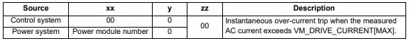 Recommended actions: • Acceleration/deceleration rate is too short • If seen during auto-tune reduce the voltage boost • Check for short circuit on the output cabling • Check integrity of the motor insulation using an insulation tester • Check feedback device wiring • Check feedback device mechanical coupling • Check feedback signals are free from noise • Is motor cable length within limits for the frame size • Reduce the values in the speed loop gain parameters — (Pr 03.010, 03.011, 03.012) or (Pr 03.013, 03.014, 03.015) • Has the phase angle autotune been completed? (RFC-S mode only) • Reduce the values in current loop gain parameters (RFC-A, RFC-S modes only) |
| Inductance | Inductance measurement out of range or motor saturation not detected |
| Trip 8 | This trip occurs in RFC-S mode when the drive has detected that the motor inductances are not suitable for the operation being attempted. The trip is either caused because the ratio or difference between Ld and Lq is too small or because the saturation characteristic of the motor cannot be measured. If the inductance ratio or difference is too small this is because one of the following conditions is true: (No-load Lq (05.072)- Ld (05.024)) / Ld (05.024) < 0.1 (No-load Lq (05.072) — Ld (05.024)) < (K / Full Scale Current Kc (11.061))H where: 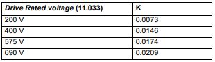 If the saturation characteristic of the motor cannot be measured this is because when the flux in the motor is changed the measured value of Ld does change sufficiently due to saturation to be measured. When half of Rated Current (05.007) is applied in the d axis of the motor in each direction the inductance must fall change at least (K / (2 x Full Scale Current Kc (11.061)). The specific reasons for each of the sub-trips are given in the table below: 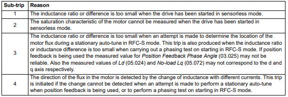 Recommended actions for sub-trip 1: • Ensure that RFC Low Speed Mode (05.064) is set to Non-salient (1), Current (2) or Current No test (3). Recommended actions for sub-trip 2: • Ensure that RFC Low Speed Mode (05.064) is set to Non-salient (1), Current (2) or Current No test (3). Recommended actions for sub-trip 3: • None. The trip acts as a warning. Recommended actions for sub-trip 4: • Stationary autotune is not possible. Perform a minimal movement or rotating autotune. • Phasing test on starting is not possible. Use a position feedback device with commutation signals or absolute position |
| Motor Too Hot | Output current overload timed out (I2t) |
| Trip 20 | The Motor Too Hot trip indicates a motor thermal overload based on the Rated Current (Pr 05.007) and Motor Thermal Time Constant (Pr 04.015). Pr 04.019 displays the motor temperature as a percentage of the maximum value. The drive will trip on Motor Too Hot when Pr 04.019 gets to 100 %. Recommended actions: • Ensure the load is not jammed / sticking • Check the load on the motor has not changed • If seen during an auto-tune test in RFC-S mode, ensure the motor Rated Current in Pr 05.007 is ≤ Heavy duty current rating of the drive • Tune the Rated Speed (Pr 05.008) (RFC-A mode only) • Check feedback signal for noise • Ensure the motor rated current is not zero • This trip can be disabled and current limiting activated on the motor overload by setting thermal protection mode Pr 04.016 to 1. |
| OHt Power | Power stage over temperature |
| Trip 22 | This trip indicates that a power stage over-temperature has been detected. From the sub-trip ‘xxyzz’, the Thermistor location which is indicating the over-temperature is identified by ‘zz’.The thermistor numbering is different for a single module type drive (i.e. no parallel board fitted) and a multi-module type drive (i.e. parallel board fitted with one or more power modules) as shown below: Single module type drive: 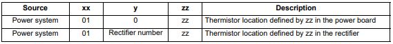 Multi-module type system: 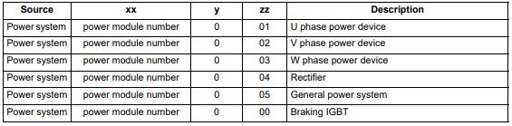 Note that the power module that has caused the trip cannot be identified except for the braking IGBT temperature measurement Recommended actions: • Check enclosure / drive fans are still functioning correctly • Force the heatsink fans to run at maximum speed • Check enclosure ventilation paths • Check enclosure door filters • Increase ventilation • Reduce the drive switching frequency • Reduce duty cycle • Increase acceleration / deceleration rates • Use S ramp (Pr 02.006) • Reduce motor load • Check the derating tables and confirm the drive is correctly sized for the application. • Use a drive with larger current / power rating |
| An Input 1 Loss | Analog input 1 current loss (Unidrive M700 / M701) |
| Trip 28 | An Input 1 Loss trip indicates that a current loss was detected in current mode on Analog input 1 (Terminal 5, 6). In 4-20 mA and 20-4 mA modes loss of input is detected if the current falls below 3 mA. Recommended actions: • Check control wiring is correct • Check control wiring is undamaged • Check the Analog Input 1 Mode (07.007) • Current signal is present and greater than 3 mA |
| Phase Loss | Supply phase loss |
| Trip 32 | The Phase Loss trip indicates that the drive has detected an input phase loss or large supply imbalance. Phase loss can be detected directly from the supply where the drive has a thyristor base charge system (Frame size 8 and above). If phase loss is detected using this method the drive trips immediately and the xx part of the sub-trip is set to 01. In all sizes of drive phase loss is also detected by monitoring the ripple in the DC bus voltage in which case the drive attempts to stop the drive before tripping unless bit 2 of Action On Trip Detection (10.037) is set to one. When phase loss is detected by monitoring the ripple in the DC bus voltage the xx part of the sub-trip is zero.  (1) Input phase loss detection can be disabled when the drive required to operate from the DC supply or from a single phase supply in Input Phase Loss Detection Mode (06.047). (2) For a parallel power-module system the rectifier number will be one as it is not possible to determine which rectifier has detected the fault. This trip does not occur in regen mode. Recommended actions: • Check the AC supply voltage balance and level at full load • Check the DC bus ripple level with an isolated oscilloscope • Check the output current stability • Check for mechanical resonance with the load • Reduce the duty cycle • Reduce the motor load • Disable the phase loss detection, set Pr 06.047 to 2. |
| Out Phase Loss | Output phase loss detected |
| Trip 98 | The Out Phase Loss trip indicates that phase loss has been detected at the drive output.  NOTE: If Pr 05.042 = 1 the physical output phases are reversed, and so sub-trip 3 refers to physical output phase V and sub-trip 2 refers to physical output phase W. Recommended actions: • Check motor and drive connections • To disable the trip set Output Phase Loss Detection Enable (06.059) = 0 |
| OI dc | Power module over current detected from IGBT on state voltage monitoring |
| Trip 109 | The OI dc trip indicates that the short circuit protection for the drive output stage has been activated. The table below shows where the trip has been detected. This trip cannot be reset until 10 s after the trip was initiated. 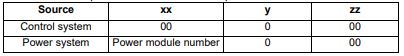 Recommended actions: • Disconnect the motor cable at the drive end and check the motor and cable insulation with an insulation tester • Replace the drive |
| Configuration | The number of power modules installed is different from the modules expected |
| Trip 111 | The Configuration trip indicates that the Number Of Power Modules Detected (11.071) does not match the previous value stored. The sub-trip value indicates the number of power modules expected. Recommended actions: • Ensure that all the power modules are correctly connected • Ensure all the power modules have powered up correctly • Ensure that the value in Pr 11.071 is set to the number of power modules connected • Set Pr 11.035 to 0 to disable the trip if it is not required This trip is also initiated if the number of external rectifiers connected to each power module is less than the number defined by Number Of Rectifiers Expected (11.096). If this is the reason for the trip the sub-trip is 10x where x is the number of external rectifiers that should be connected. Recommended actions: • Ensure that all the external rectifiers are connected correctly • Ensure that the value in Number Of Rectifiers Expected (11.096) is correct |
Alarm Indications
In any mode, an alarm is an indication given on the display by alternating the alarm string with the drive status string on the first row and showing the alarm symbol in the last character in the first row. If an action is not taken to eliminate any alarm except «Auto Tune and Limit Switch» the drive may eventually trip. Alarms are not displayed when a parameter is being edited, but the user will still see the alarm character on the upper row.
| Alarm string | Description |
|---|---|
| Brake Resistor | Brake resistor overload. Braking Resistor Thermal Accumulator (10.039) in the drive has reached 75.0 % of the value at which the drive will trip. |
| Motor Overload | Motor Protection Accumulator (04.019) in the drive has reached 75.0 % of the value at which the drive will trip and the load on the drive is >100 %. |
| Ind Overload | Regen inductor overload. Inductor Protection Accumulator (04.019) in the drive has reached 75.0 % of the value at which the drive will trip and the load on the drive is >100 %. |
| Drive Overload | Drive over temperature. Percentage Of Drive Thermal Trip Level (07.036) in the drive is greater than 90 %. |
| Auto Tune | The autotune procedure has been initialized and an autotune in progress. |
| Limit Switch | Limit switch active. Indicates that a limit switch is active and that is causing the motor to be stopped. |
Status Indications
| Upper row string | Description | Drive output stage |
|---|---|---|
| Inhibit | The drive is inhibited and cannot be run. The Safe Torque Off signal is not applied to Safe Torque Off terminals or Pr 06.015 is set to 0 | Disabled |
| Ready | The drive is ready to run. The drive enable is active, but the drive inverter is not active because the final drive run is not active | Disabled |
| Stop | The drive is stopped / holding zero speed. | Enabled |
| Run | The drive is active and running | Enabled |
| Scan | The drive is enabled in Regen mode and is trying to synchronize to the supply | Enabled |
| Supply Loss | Supply loss condition has been detected | Enabled |
| Deceleration | The motor is being decelerated to zero speed / frequency because the final drive run has been deactivated. | Enabled |
| dc injection | The drive is applying dc injection braking | Enabled |
| Position | Positioning / position control is active during an orientation stop | Enabled |
| Trip | The drive has tripped and no longer controlling the motor. The trip code appears in the lower display | Disabled |
| Active | The regen unit is enabled and synchronized to the supply | Enabled |
| Under Voltage |
The drive is in the under voltage state either in low voltage or high voltage mode | Disabled |
| Heat | The motor pre-heat function is active | Enabled |
| Phasing | The drive is performing a ‘phasing test on enable’ | Enabled |
Option module and NV Media Card and other status indications at power-up
| First row string | Second row string | Status |
|---|---|---|
| Booting | Parameters | Parameters are being loaded |
| Drive parameters are being loaded from a NV Media Card | ||
| Booting | User Program | User program being loaded |
| User program is being loaded from a NV Media Card to the drive | ||
| Booting | Option Program | User program being loaded |
| User program is being loaded from a NV Media Card to the option module in slot X | ||
| Writing To | NV Card | Data being written to NV Media Card |
| Data is being written to a NV Media Card to ensure that its copy of the drive parameters is correct because the drive is in Auto or Boot mode | ||
| Waiting For | Power System | Waiting for power stage |
| The drive is waiting for the processor in the power stage to respond after power-up | ||
| Waiting For | Options | Waiting for an option module |
| The drive is waiting for the Options Modules to respond after power-up | ||
| Uploading From |
Options | Loading parameter database |
| At power-up it may be necessary to update the parameter database held by the drive because an option module has changed or because an applications module has requested changes to the parameter structure. This may involve data transfer between the drive an option modules. During this period ‘Uploading From Options’ is displayed |
Programming error indications
Following are the error message displayed on the drive keypad when an error occurs during programming of drive firmware.
| Error String | Reason | Solution |
|---|---|---|
| Error 1 | There is not enough drive memory requested by all the option modules. | Power down drive and remove some of the option modules until the message disappears. |
| Error 2 | At least one option module did not acknowledge the reset request. | Power cycle drive |
| Error 3 | The boot loader failed to erase the processor flash | Power cycle drive and try again. If problem persists, return drive |
| Error 4 | The boot loader failed to program the processor flash | Power cycle drive and try again. If problem persists, return drive |
| Error 5 | One option module did not initialize correctly. Option module did not set Ready to Run flag. | Remove faulty option module |
Need further help?
If you have an AC / DC drive module breakdown or stability issue our engineers are able to analyse the whole machine to identify where the control issues lie. Our extensive experience in retrofit and new projects means we have the knowledge to look deep into the control system where we commonly find the peripheral devices are faulty rather than the drive module.
Our team of engineers are able to offer on site service and breakdown support throughout the UK to get you up and running again quickly.

Высокопроизводительный привод переменного тока M700
Руководство по вводу в эксплуатацию
с Unidrive M700, M701, M702 без обратной связи по положению
Двигатели от 11 до 240 кВт взаимозаменяемые версии серий 1,500 и 3,000 с приводом
Артикул: 6069 эн – 2022.06/с
ВВЕДЕНИЕ
1 — ВВЕДЕНИЕ
Перед настройкой привода следуйте инструкциям по безопасности и установке для двигателей Dyneo+ и приводов Unidrive M70x, описанным в соответствующих руководствах. Двигатели Dyneo+: http://www.leroy-somer.com/documentation_pdf/5411_en.pdf Привод Unidrive M70x: см. Руководство по началу работы и соответствующее Руководство по установке питания (доступно в Control Techniques). webсайт).
· Установка и ввод в эксплуатацию должны выполняться квалифицированным, компетентным и уполномоченным персоналом.
Затем выполните быстрый ввод в эксплуатацию, описанный в пункте 2, с заводскими настройками.
Требования: · Убедитесь, что на приводе установлена версия микропрограммы, равная или выше V01.20.00.00. · Не включайте процедуру автонастройки. · Параметры, указанные в таблицах данных двигателя из приложения, применимы только к номинальной мощности привода Unidrive M70x, указанной для
каждую строку данных. Если используется привод с другим номиналом, то коэффициент усиления Kp регулятора тока (Pr 04.013) и коэффициент усиления Ki регулятора тока (Pr 04.014) необходимо масштабировать, как описано ниже:
Новое значение = значение приложения x (KC новый привод / KC дополнительный привод) Значения для KC можно найти в Справочном руководстве по параметрам, в разделе «Текущие номиналы» или в интерактивной справке программного обеспечения Control Techniques Connect.
Dyneo+ с Unidrive M70x без обратной связи по положению Руководство по вводу в эксплуатацию
3
6069 эн – 2022.06/с
ВВОД В ЭКСПЛУАТАЦИЮ UNIDRIVE M70X БЕЗ ОБРАТНОЙ СВЯЗИ ПО ПОЛОЖЕНИЮ
2 – ВВОД В ЭКСПЛУАТАЦИЮ С UNIDRIVE M70x БЕЗ ОБРАТНОЙ СВЯЗИ ПО ПОЛОЖЕНИЮ
Режим RFC-S для взаимозаменяемых двигателей Dyneo+ с постоянными магнитами без обратной связи по положению (без датчиков)
Действие
Описание
Перед включением
Убедитесь, что: · Сигнал включения привода не подается (клемма 31 на Unidrive M700/M701 и клеммы 11 и 13 на Unidrive M702) · Сигнал «Работа» не подается · Двигатель подключен
Если при включении привода отображается режим Open Loop или RFC-A:
· Установите Pr 00.048 = RFC-S (3). · Если частота сети 60 Гц, установите Pr 00.000 = 1254, иначе, если частота сети 50 Гц, установите Pr 00.000 = 1253.
Включите привод
Если при включении привода отображается режим RFC-S:
· Если частота сети 60 Гц, установите Pr 00.000 = 1244, иначе, если частота сети 50 Гц, установите Pr 00.000 = 1233.
Доступ к расширенному меню с клавиатуры Установка максимальной скорости
Установите коэффициенты ускорения и замедления
Настройка термистора двигателя
Нажмите красную кнопку сброса или переключите логический вход сброса. Эти действия оставят диск в режиме RFC-S с параметрами по умолчанию. Привод будет находиться в отключенном состоянии, но соответствующие отключения регулируются настройками в рамках этой процедуры.
Чтобы получить доступ ко всем меню, необходимым для ввода в эксплуатацию, установите Pr 00.0049 = Все меню (1).
Напоминание: выберите меню с помощью стрелок влево и вправо. Параметры выбираются стрелками вверх и вниз.
Установите максимальную скорость в Pr 01.006 (об/мин).
Задайте: · Скорость ускорения в Pr 02.011 (с до Pr 01.006) — значение 20 с подходит для большинства приложений. · Скорость замедления в Pr 02.021 (с до Pr 01.006) – значение 20 с подходит для большинства приложений. · Рamp Единицы скорости Pr 02.039 = Вкл. (1)
Если тормозной резистор установлен, установите Pr 02.004 = Fast (0). Также убедитесь, что Pr 10.030, Pr 10.031 и Pr 10.061 установлены правильно, в противном случае могут наблюдаться постоянные отключения «Brake R Too Hot».
Термистор PTC двигателя должен быть подключен к приводу: · M700/M701: Подключите термистор к аналоговому входу 3 (клеммы 8 и 11). · M702 (с кодом даты 1710 или более поздней): Подключите термистор к цифровому входу 5 / аналоговому входу 3 (клеммы 8 и 10).
Чтобы привод управлял термистором: · Установите режим аналогового входа 3 Pr 07.015 = Therm short Cct (7).
Если при подключении термистора недостаточно входов, может потребоваться установка модуля SI-I/O.
4
Dyneo+ с Unidrive M70x без обратной связи по положению Руководство по вводу в эксплуатацию
6069 эн – 2022.06/с
ВВОД В ЭКСПЛУАТАЦИЮ UNIDRIVE M70X БЕЗ ОБРАТНОЙ СВЯЗИ ПО ПОЛОЖЕНИЮ
Действие
Введите данные паспортной таблички двигателя
Описание См. таблицы двигателей Dyneo+ в Приложении. Выберите таблицу, соответствующую диапазону скорости двигателя (1500 или 3000 об/мин). Затем в зависимости от типа двигателя и его мощности выберите строку, которая соответствует объему.tage, частота питания и номинальная скорость приложения. Из этой строки задайте в накопителе значения всех параметров, перечисленных в таблице. Если нагрузка имеет большую инерцию, может потребоваться увеличить Pr 03.010.
ПРИМЕЧАНИЕ. Если тип двигателя не указан в таблице, значит, он принадлежит к компактной серии. В этом случае обратитесь в службу технической поддержки Control Techniques.
Example: Для двигателя серии 1500, ЛШРМ 160МР1 – 11 кВт 400 В – 50 Гц с номинальной скоростью 1500 об/мин, значения параметров, которые необходимо установить в приводе, соответствуют значениям зеленой линии, как показано ниже:
Тип МОТОР
ЛШРМ 160 МР1
ГАММЕ 1500 мин-1
ВАРИАТОР
НАСТРОЙКИ
Муфта
#03.010 #03.011 #04.013 #04.014 #04.015 #05.007 #05.008 #05.009 #05.017 #05.024 #05.033 #05.069 #05.072 #05.075 #05.078 #05.082 #05.084 #05.087
кВт М700
Гц Усиление Усиление Усиление Усиление Константе Курант
Сопротивление
Витесс Напряжение
Ld
Vitesse Vitesse Courant Courant thermoque номинальный (мин-1) (В)
Кр Ки Кр Ки
(S)
(A)
Статор ()
(М)
БЭМП (В/
кммин-1)
Куран де Дефо
(%)
Lq @0A (мГн)
IQ (%)
Lq @ Iq Id (мГн) (%)
Угол
Lq @ Id (мГн)
пара (°)
11 44-00172 У 50 0,005 0,05 152 269 800 21,0 1500 400 0,31582 7,626 72,1 236 68,540 73 44,845 -108 68,540 56
11 44-00172 У 60 0,005 0,05 152 269 800 20,3 1800 400 0,31582 7,626 72,1 244 68,540 73 44,845 -108 68,540 56
12,7 44-00172 У 60 0,005 0,05 152 269 800 21,2 1800 460 0,31582 7,626 72,1 233 68,540 73 44,845 -108 68,540 56
19,1 64-00420 Д 87 0,005 0,05 124 219 800 38,2 2600 400 0,10527 2,542 41,6 218 22,847 73 14,948 -108 22,850 56
Дополнительные настройки
Сохранить параметры
ПРИМЕЧАНИЕ. При настройке Pr 05.069 может потребоваться увеличить введенное значение, чтобы фактическое значение отключения, отображаемое в Pr 05.068, было близко (но не больше) к требуемому значению.
Задавать :
· Режим обратной связи RFC (Pr 03.024) = Без датчика · Уровень обнаружения ошибки P1 (Pr 03.040) = 0 · Обнаружение ошибки термистора P1 (Pr 03.123) = Нет (0) · Ограничение тока двигателя (Pr 04.005) = 120% макс. · Ток рекуперации Предел (Pr 04.006) = 120 % макс · Предел симметричного тока (Pr 04.007) = 120 % макс · Постоянная времени фильтра опорного тока 1 (Pr 04.012) = 1 мс ]
· Режим тепловой защиты (Pr 04.016) = Отключен (4) · Максимальное масштабирование пользовательского тока (Pr 04.024) = макс. 120 % · Количество пар полюсов двигателя (Pr 05.011) = 2 · Максимальная частота коммутации (Pr 05.018) = 3 кГц (1) ) · Включить высокоскоростной режим (Pr 05.022) = Включить (2) · Коэффициент усиления управления потоком (Pr 05.027) = 0.1 · Минимальная частота переключения (Pr 05.038) = 3 кГц (1) · Voltage Запас Pr 05.041 = 5 %. [Не устанавливайте меньшее значение. Увеличьте это значение до 10 %, если двигатель нестабилен в области ослабления поля] · Режим низкой скорости RFC (Pr 05.064) = впрыск · Управление крутящим моментом Saliency Выберите Pr 05.065 = Авто (3) [Убедитесь, что Pr 05.066 = Высокий (2) ) в противном случае проверьте значение, введенное для Pr 05.087 из таблицы] · Инверсная характеристика насыщения (Pr 05.070) = Вкл. (1) · Ток в бессенсорном режиме на низкой скорости (Pr 05.071) = 60 % [Примечание. скорость и 20% от номинальной скорости двигателя]
· Режим остановки (Pr 06.001) = Ramp (1) · Удержание нулевой скорости (Pr 06.008) = отключено (0)
Выберите «Сохранить параметры» в Pr mm.000 и нажмите красную кнопку сброса или переключите цифровой вход сброса.
Привод готов к запуску.
Dyneo+ с Unidrive M70x без обратной связи по положению Руководство по вводу в эксплуатацию
5
6069 эн – 2022.06/с
ВВОД В ЭКСПЛУАТАЦИЮ С UNIDRIAVPEPME7N0DXIX БЕЗ ОБРАТНОЙ СВЯЗИ ПО ПОЛОЖЕНИЮ
Тип двигателя
ПРИВОД кВт
M70x
Связь
1500 об/мин ДИАПАЗОН ПАРАМЕТРОВ
#03.010 #03.011 #04.013 #04.014 #04.015 #05.007 #05.008 #05.009 #05.017 #05.024 #05.033 #05.069 #05.072 #05.075
#05.078
#05.082
# 05.084 # 05.087
Hz
Увеличение скорости Кр
Скорость Ток Ток Тепловой Номинал
Усиление Усиление Усиление постоянный ток
Ки Кр Ки
(S)
(A)
Номинальная скорость (об / мин)
Номинальный статор
обtagе Сопротивление
(V)
()
Ld (мГн)
OverBEMF текущий Lq @0A
(В/об/мин) уровень срабатывания (мГн) (%)
IQ (%)
Lq @ Iq (мГн)
Идентификатор (%)
Lq @ Id (мГн)
Угол крутящего момента
(°)
11 44-00172 Д 50 0.005 0.05 152 269 800 21.0 1500 400 0.31582 7.626 72.1 236 68.540 73
ЛШРМ 160 МР1
11 12.7
44-00172 44-00172
Д 60 0.005 Д 60 0.005
0.05 0.05
152 152
269 269
800 800
20.3 1800 400 0.31582 7.626 72.1 21.2 1800 460 0.31582 7.626 72.1
244 68.540 233 68.540
73 73
19.1 64-00420 Д 87 0.005 0.05 124 219 800 38.2 2600 400 0.10527 2.542 41.6 218 22.847 73
15 54-00300 Д 50 0.005 0.05 304 493 800 27.5 1500 400 0.28454 7.478 78.7 199 67.889 69
ЛШРМ 160 ЛР1
15 17.3
54-00270 54-00270
Д 60 0.005 Д 60 0.005
0.05 0.05
234 234
381 381
800 800
26.8 1800 400 0.28454 7.478 78.7 26.7 1800 460 0.28454 7.478 78.7
204 67.889 204 67.889
69 69
26.0 64-00470 Д 87 0.005 0.05 136 221 800 48.6 2600 400 0.09485 2.493 45.4 189 22.630 69
18.5 64-00420 Д 50 0.03 0.1 277 444 1000 35.9 1500 400 0.2133 5.676 73.1 181 43.301 71
ЛШРМ 180 М1
18.5 21.3
64-00420 64-00420
Д 60 0.03 Д 60 0.03
0.1 0.1
277 444 1000 35.1 1800 400 0.2133 5.676 73.1 277 444 1000 35.5 1800 460 0.2133 5.676 73.1
185 43.301 183 43.301
71 71
32.1 74-00660 Д 87 0.03 0.1 145 232 1000 62.9 2600 400 0.0711 1.892 42.2 174 14.434 71
22 64-00420 Д 50 0.03 0.1 207 281 1000 42.2 1500 400 0.13516 4.253 71.6 196 33.058 73
ЛШРМ 180 Л1
22 25.4
64-00420 64-00420
Д 60 0.03 Д 60 0.03
0.1 0.1
207 281 1000 40.1 1800 400 0.13516 4.253 71.6 207 281 1000 41.1 1800 460 0.13516 4.253 71.6
207 33.058 202 33.058
73 73
38.1 74-00770 Д 87 0.03 0.1 127 172 1000 73.5 2600 400 0.04505 1.418 41.3 189 11.019 73
30 64-00470 Д 50 0.03 0.1 190 252 1000 57.0 1500 400 0.10831 3.492 71.6 174 27.497 69
LSHRM 200 LQ1 30 64-00470 Y 60 0.03 0.1 190 252 1000 54.9 1800 400 0.10831 3.492 71.6 181 27.497 69 34.6 64-00470 Y 60 0.03 0.1 190 252 1000 56.1 1800 460 0.10831 3.492 71.6 177 27.497 69
52 74-01000 Д 87 0.03 0.1 135 179 1000 99.3 2600 400 0.03611 1.164 41.3 168 9.166 69
37 74-00660 Д 50 0.03 0.1 232 290 1000 70.1 1500 400 0.08873 3.028 72.3 164 24.063 69
ЛШРМ 225 СЗ1
37 42.7
74-00660 74-00660
Д 60 0.03 Д 60 0.03
0.1 0.1
232 290 1000 68.4 1800 400 0.08873 3.028 72.3 232 290 1000 69.2 1800 460 0.08873 3.028 72.3
168 24.063 166 24.063
69 69
64.2 84-01340 Д 87 0.03 0.1 157 196 1000 122 2600 400 0.02958 1.009 41.8 157 8.021 69
45 74-00770 Д 50 0.005 0.1 220 172 1200 82.1 1500 400 0.04505 2.467 76.6 201 23.645 67
ЛШРМ 225 МГ
45 54.3
74-00770 74-00770
Д 60 0.005 Д 60 0.005
0.1 0.1
220 172 1200 79.6 1800 400 0.04505 2.467 76.6 220 172 1200 83.1 1800 460 0.04505 2.467 76.6
207 23.645 198 23.645
67 67
79.2 84-01570 Д 87 0.005 0.1 150 117 1200 142 2600 400 0.01502 0.822 44.2 195 7.882 67
55 74-01000 Д 50 0.005 0.1 234 168 1200 99.4 1500 400 0.03388 2.015 76.6 199 19.664 67
LSHRM 250 ME 55 74-01000 y 60 0.005 0.1 234 168 1200 94.7 1800 400 0.03388 2.015 76.6 208 19.664 67 64 74-01000 y 60 0.005 0.1 234 168 1200 97.8 1800 460 0.03388 2.015 76.6 202 19.664 67 XNUMX XNUMX XNUMX XNUMX XNUMX XNUMX XNUMX XNUMX XNUMX XNUMX XNUMX XNUMX XNUMX XNUMX XNUMX XNUMX XNUMX XNUMX XNUMX XNUMX XNUMX XNUMX XNUMX XNUMX XNUMX XNUMX
95 94-02000 Д 87 0.005 0.1 136 98 1200 176 2600 400 0.01129 0.672 44.2 189 6.555 67
75 84-01340 Д 50 0.005 0.1 261 163 1200 134 1500 400 0.02461 1.677 81.7 185 16.736 63
ЛШРМ 280 СД
75 86.4
84-01340 84-01340
Д 60 0.005 Д 60 0.005
0.1 0.1
261 163 1200 130 1800 400 0.02461 1.677 81.7 261 163 1200 131 1800 460 0.02461 1.677 81.7
190 16.736 189 16.736
63 63
131 94-02240 Д 87 0.005 0.1 127 159 1200 231 2600 400 0.00821 0.559 47.2 180 5.579 63
90 84-01570 Д 50 0.005 0.1 261 154 1200 163 1500 400 0.01982 1.432 80.4 174 14.403 63
ЛШРМ 280 МД
90 104
84-01570 84-01570
Д 60 0.005 Д 60 0.005
0.1 0.1
261 154 1200 158 1800 400 0.01982 1.432 80.4 261 154 1200 155 1800 460 0.01982 1.432 80.4
179 14.403 182 14.403
63 63
156 104-02700 Д 87 0.005 0.1 149 177 1200 279 2600 400 0.00661 0.477 46.4 171 4.801 63
110 94-02000 Д 50 0.005 0.1 236 133 1200 199 1500 400 0.01534 1.161 76.6 165 11.750 61
ЛШРМ 315 СН1
110 132
94-02000 94-02240
Д 60 0.005 Д 60 0.005
0.1 0.1
236 133 1200 195 1800 400 0.01534 1.161 76.6 264 149 1200 202 1800 460 0.01534 1.161 76.6
168 11.750 163 11.750
61 61
192 114-04170 Д 87 0.005 0.1 164 185 1200 342 2600 400 0.00511 0.387 44.2 161 3.917 61
132 94-02240 Д 50 0.005 0.1 240 92 1400 235 1500 400 0.00952 1.057 86 194 9.591 59
ЛШРМ 315 МП
132 152
94-02240 94-02240
Д 60 0.005 Д 60 0.005
0.1 0.1
240 240
92 92
1400 234 1800 400 0.00952 1.057 1400 233 1800 460 0.00952 1.057
86 86
195 9.591 196 9.591
59 59
229 114-04170 Д 87 0.005 0.1 149 115 1400 415 2600 400 0.00317 0.352 49.6 186 3.197 59
160 104-03770 Д 50 0.005 0.1 264 96 1400 304 1500 400 0.00604 0.712 75.2 192 6.520 59
ЛШРМ 315 МП 160 104-02700 Y 60 0.005 0.1 223 81 1400 280 1800 400 0.00604 0.712 75.2 209 6.520 59
184 104-03770 Д 60 0.005 0.1 264 96 1400 294 1800 460 0.00604 0.712 75.2 198 6.520 59
200 114-04170 Д 50 0.005 0.1 247 82 1400 377 1500 400 0.00454 0.583 75.8 188 5.413 59
ЛШРМ 315 МР 200 114-04170 Д 60 0.005 0.1 247 82 1400 319 1800 400 0.00454 0.583 75.8 203 5.413 59
230 114-04170 Д 60 0.005 0.1 247 82 1400 366 1800 460 0.00454 0.583 75.8 193 5.413 59
75 84-01340 Д 50 0.005 0.1 261 163 1400 134 1500 400 0.02461 1.677 81.7 185 16.736 63
ФЛШРМ 280 СБ
75 86.4
84-01340 84-01340
Д 60 0.005 Д 60 0.005
0.1 0.1
261 163 1400 130 1800 400 0.02461 1.677 81.7 261 163 1400 131 1800 460 0.02461 1.677 81.7
190 16.736 189 16.736
63 63
131 94-02240 Д 87 0.005 0.1 127 80 1400 231 2600 400 0.0082 0.559 47.2 180 5.579 63
90 84-01570 Д 50 0.005 0.1 261 154 1500 163 1500 400 0.01982 1.432 80.4 174 14.403 63
ФЛШРМ 280 МД
90 104
84-01570 84-01570
Д 60 0.005 Д 60 0.005
0.1 0.1
261 154 1500 158 1800 400 0.01982 1.432 80.4 261 154 1500 155 1800 460 0.01982 1.432 80.4
179 14.403 182 14.403
63 63
156 104-02700 Д 87 0.005 0.1 149 95 1500 279 2600 400 0.00661 0.477 46.4 171 4.801 63
110 94-02000 Д 50 0.005 0.1 236 133 1500 199 1500 400 0.01534 1.161 76.6 165 11.750 61
FLSHRM 315 STB 110 94-02000 Y 60 0.005 0.1 236 133 1500 195 1800 400 0.01534 1.161 76.6 168 11.750 61 131 94-02240 Y 60 0.005 0.1 264 149 1500 202 1800 460 0.01534 1.161 76.6 163 11.750 61
192 114-04170 Д 87 0.005 0.1 164 92 1500 342 2600 400 0.00511 0.387 44.2 161 3.917 61
132 94-02240 Д 50 0.005 0.1 240 92 1600 236 1500 400 0.00952 1.057 86 194 9.591 59
ФЛШРМ 315 М
132 152
94-02240 94-02240
Д 60 0.005 Д 60 0.005
0.1 0.1
240 240
92 92
1600 234 1800 400 0.00952 1.057 1600 233 1800 460 0.00952 1.057
86 86
195 9.591 196 9.591
59 59
229 114-04170 Д 87 0.005 0.1 149 57 1600 415 2600 400 0.00317 0.352 49.6 186 3.197 59
160 104-03770 Д 50 0.005 0.1 264 96 1600 304 1500 400 0.00604 0.712 75.2 192 6.520 59
ФЛШРМ 315 ЛА 160 104-02700 Y 60 0.005 0.1 223 81 1600 280 1800 400 0.00604 0.712 75.2 209 6.520 59
184 104-03770 Д 60 0.005 0.1 264 96 1600 294 1800 460 0.00604 0.712 75.2 198 6.520 59
200 114-04170 Д 50 0.005 0.1 247 82 1600 377 1500 400 0.00454 0.583 75.8 188 5.413 59
ФЛШРМ 315 ЛБ 200 114-04170 Д 60 0.005 0.1 247 82 1600 349 1800 400 0.00454 0.583 75.8 203 5.413 59
230 114-04170 Д 60 0.005 0.1 247 82 1600 366 1800 460 0.00454 0.583 75.8 193 5.413 59
240 114-04800 Д 50 0.005 0.1 241 78 1600 457 1500 400 0.00385 0.512 74.5 172 4.780 59
ФЛШРМ 315 ЛЦ 240 114-04170 Д 60 0.005 0.1 217 70 1600 429 1800 400 0.00385 0.512 74.5 183 4.780 59
276 114-04800 Д 60 0.005 0.1 241 78 1600 443 1800 460 0.00385 0.512 74.5 177 4.780 59
44.845 -108 68.540 56 44.845 -108 68.540 56 44.845 -108 68.540 56 14.948 -108 22.850 56 40.485 -110 67.890 58 40.485 -110 67.890 58 40.485 -110 67.890 58 13.495 -110 22.630 58 31.534 -109 43.300 57 31.534 -109 43.300 57 31.534 -109 43.300 57 10.511 -109 14.430 57 25.019 -108 33.060 56 25.019 -108 33.060 56 25.019 -108 33.060 56 8.340 -108 11.020 56 19.675 -110 27.500 58 19.675 -110 27.500 58 19.675 -110 27.500 58 6.558 -110 9.170 58 16.697 -110 24.060 58 16.697 -110 24.060 58 16.697 -110 24.060 58 5.566 -110 8.020 58 13.172 -111 23.640 59 13.172 -111 23.640 59 13.172 -111 23.640Р59Р4.391Р111Р7.880Р59Р10.923А 111, 19.660 -59 10.923 111 19.660 -59 10.923 111 19.660 -59 3.641 111 6.550 -59 8.988 114 16.740 -61 8.988 114 16.740 -61 8.988 114 16.740 -61 2.996 114 5.580 -61 7.519 114 14.400 -61 7.519 114 14.400 -61 7.519 114 14.400 -61 -2.506 114 -4.800 -61 -6.646 -115 -11.750. 62 -6.646 115 11.750 62 -6.646 115 11.750 62 -2.215 115 3.920 62 -5.620 116 9.590 63 -5.620 116 9.590 63 -5.620 116 9.590 63 -1.873 116 -3.200 63 3.800 116 -6.520 63 3.800 116 -6.520 63 3.800 116 -6.520 63 3.096 116 -5.410 63 3.096 116 -5.410 63 3.096 116 5.410 63
8.988 -114 16.740 61 8.988 -114 16.740 61 8.988 -114 16.740 61 2.996 -114 5.580 61 7.519 -114 14.400 61 7.519 -114 14.400 61 7.519 -114 14.400 61 2.506 -114 4.800 61 6.646. 115 -11.750 62 6.646 115 -11.750 62 6.646 115 -11.750 62 2.215 115 -3.920 62 5.620 116 -9.590 63 5.620 116 -9.590 63 5.620 116 -9.590 63 1.873 116 -3.200 63 3.800 116 -6.520 63 3.800 116 -6.520 63 3.800 116 -6.520 63 3.096 116 -5.410 63 3.096 116 -5.410 63 3.096 116 -5.410 63 2.550 116 -4.780 63 2.550
6
Dyneo+ с Unidrive M70x без обратной связи по положению Руководство по вводу в эксплуатацию
6069 эн – 2022.06/с
ВВОД В ЭКСПЛУАТАЦИЮ С ПОМОЩЬЮ UNIDRIVAEPPME7N0DXIX БЕЗ ОБРАТНОЙ СВЯЗИ ПО ПОЛОЖЕНИЮ
Тип двигателя
ПРИВОД кВт
M70x
Связь
3000 об/мин ДИАПАЗОН ПАРАМЕТРОВ
#03.010 #03.011 #04.013 #04.014 #04.015 #05.007 #05.008 #05.009 #05.017 #05.024 #05.033 #05.069 #05.072 #05.075
#05.078
#05.082
# 05.084 # 05.087
Hz
Увеличение скорости Кр
Скорость Ток Ток Тепловой Номинал
Усиление Усиление Усиление постоянный ток
Ки Кр Ки
(S)
(A)
Номинальная скорость (об / мин)
Номинальный статор
обtagе Сопротивление
(V)
()
Ld (мГн)
OverBEMF текущий Lq @0A
(В/об/мин) уровень срабатывания (мГн) (%)
IQ (%)
Lq @ Iq (мГн)
Идентификатор (%)
Lq @ Id (мГн)
Угол крутящего момента
(°)
11 44-00172 Д 100 0.005 0.05 95 213 800 20.3 3000 400 0.25015 4.781 43.3 238 41.329 73
ЛШРМ 160 МР1
11 12.7
44-00172 44-00172
Д 120 0.005 0.05 Д 120 0.005 0.05
95 95
213 213
800 800
19.8 3600 400 0.25015 4.781 43.3 19.9 3600 460 0.25015 4.781 43.3
244 41.329 243 41.329
73 73
19.1 64-00420 Д 173 0.005 0.05 78 173 800 35.8 5200 400 0.08338 1.594 25 223 13.776 73
15 54-00300 Д 100 0.005 0.05 117 223 800 27.7 3000 400 0.12877 2.884 39.3 254 25.538 75
ЛШРМ 160 МР1
15 17.3
54-00270 64-00350
Д 120 0.005 0.05 Д 120 0.005 0.05
90 117
172 223
800 800
27.1 3600 400 0.12877 2.884 39.3 28.2 3600 460 0.12877 2.884 39.3
259 25.538 249 25.538
75 75
26.0 64-00470 Д 173 0.005 0.05 52 100 800 50.9 5200 400 0.04292 0.961 22.7 226 8.513 75
18.5 64-00350 Д 100 0.005 0.05 117 223 800 33.7 3000 400 0.12877 2.884 39.3 209 25.538 71
ЛШРМ 160 ЛР1
18.5 21.3
64-00350 64-00350
Д 120 0.005 0.05 Д 120 0.005 0.05
117 117
223 223
800 800
32.9 3600 400 0.12877 2.884 39.3 33.1 3600 460 0.12877 2.884 39.3
214 25.538 212 25.538
71 71
32.1 74-00660 Д 173 0.005 0.05 74 140 800 61.8 5200 400 0.0429 0.961 22.7 186 8.513 71
22 64-00420 Д 100 0.03 0.1 104 192 800 41.8 3000 400 0.0925 2.134 38.2 216 15.79 76
ЛШРМ 180 М1
22 25.5
64-00420 64-00420
Д 120 0.03 Д 120 0.03
0.1 0.1
104 104
192 192
800 800
40.2 3600 400 0.0925 2.134 38.2 41.4 3600 460 0.0925 2.134 38.2
224 15.79 218 15.79
76 76
38.1 74-00770 Д 173 0.03 0.1 64 118 800 73.6 5200 400 0.0308 0.711 22 200 5.263 76
30 64-00470 Д 100 0.03 0.1 116 215 800 56.7 3000 400 0.0925 2.134 38.2 159 15.79 69
ЛШРМ 200 LQ1 30 64-00470 Y 120 0.03 0.1 116 215 800 57.1 3600 400 0.0925 2.134 38.2 158 15.79 69
34.7 64-00470 Д 120 0.03 0.1 116 215 800 56.5 3600 460 0.0925 2.134 38.2 160 15.79 69
37 74-00660 Д 100 0.03 0.1 109 174 800 69.9 3000 400 0.05333 1.419 36.6 178 10.825 71
ЛШРМ 200 LQ1 37 74-00660 Y 120 0.03 0.1 109 174 800 68.8 3600 400 0.05333 1.419 36.6 181 10.825 71
42.9 74-00660 Д 120 0.03 0.1 109 174 800 69 3600 460 0.05333 1.419 36.6 181 10.825 71
45 74-00770 Д 100 0.03 0.1 106 142 800 84.1 3000 400 0.03715 1.185 37.8 180 9.208 71
ЛШРМ 225 МГ1 45 74-00770 Y 120 0.03 0.1 106 142 800 82 3600 400 0.03715 1.185 37.8 184 9.208 71
52 74-00770 Д 120 0.03 0.1 106 142 800 83.4 3600 460 0.03715 1.185 37.8 181 9.208 71
55 74-01000 Y 100 0.005 0.1 118 104 1100 100 3000 400 0.02106 1.019 43.4 226 9.52
71
ЛШРМ 250 МЭ 55 74-01000 Y 120 0.005 0.1 118 104 1100 101 3600 400 0.02106 1.019 43.4 225 9.52
71
63.7 74-01000 Y 120 0.005 0.1 118 104 1100 100 3600 460 0.02106 1.019 43.4 226 9.52
71
75 84-01340 Д 100 0.005 0.1 123 109 1100 138 3000 400 0.01637 0.794 38.3 185 7.412 65
ЛШРМ 280 СК 75 84-01340 Д 120 0.005 0.1 123 109 1100 136 3600 400 0.01637 0.794 38.3 187 7.412 65
86.3 84-01340 Д 120 0.005 0.1 123 109 1100 135 3600 460 0.01637 0.794 38.3 189 7.412 65
90 84-01570 Д 100 0.005 0.1 112 88 1100 167 3000 400 0.01125 0.617 38.3 190 5.911 65
ЛШРМ 280 МС 90 84-01570 Y 120 0.005 0.1 112 88 1100 160 3600 400 0.01125 0.617 38.3 198 5.911 65
104 94-02000 Д 120 0.005 0.1 125 98 1100 168 3600 460 0.01125 0.617 38.3 189 5.911 65
110 94-02000 Д 100 0.005 0.1 102 72 1100 201 3000 400 0.00836 0.504 38.3 189 4.916 69
ЛШРМ 315 СН1 110 94-02000 Д 120 0.005 0.1 102 72 1100 195 3600 400 0.00836 0.504 38.3 195 4.916 69
127 94-02000 Д 120 0.005 0.1 102 72 1100 197 3600 460 0.00836 0.504 38.3 193 4.916 69
132 94-02240 Д 100 0.005 0.1 107 70 1100 237 3000 400 0.00722 0.469 40.2 178 4.639 69
ЛШРМ 315 МН1 132 94-02240 Д 120 0.005 0.1 107 70 1100 234 3600 400 0.00722 0.469 40.2 181 4.639 69
152 94-02240 Д 120 0.005 0.1 107 70 1100 232 3600 460 0.00722 0.469 40.2 182 4.639 69
160 104-02700 Д 100 0.005 0.1 112 66 1100 289 3000 400 0.00495 0.358 40.2 188 3.601 65
ЛШРМ 315 МН1 160 104-02700 Д 120 0.005 0.1 112 66 1100 273 3600 400 0.00495 0.358 40.2 199 3.601 65
184 104-02700 Д 120 0.005 0.1 112 66 1100 283 3600 460 0.00495 0.358 40.2 192 3.601 65
200 114-04170 Д 100 0.005 0.1 123 69 1100 366 3000 400 0.00383 0.29 38.3 172 2.937 63
ЛШРМ 315 МН1 200 114-04170 Д 120 0.005 0.1 123 69 1100 365 3600 400 0.00383 0.29 38.3 173 2.937 63
233 114-04170 Д 120 0.005 0.1 123 69 1100 359 3600 460 0.00383 0.29 38.3 175 2.937 63
75 84-01340 y 100 0.005 0.1 123 109 1800 138 3000 400 0.01637 0.794 38.3 185 7.412 65 FLSHRM 280 SA 75 84-01340 Y 120 0.005 0.1 123 109 1800 136 3600 400 0.01637 0.794 38.3 187 7.412 65 XNUMX XNUMX XNUMX XNUMX XNUMX XNUMX XNUMX XNUMX XNUMX XNUMX XNUMX XNUMX XNUMX XNUMX XNUMX XNUMX XNUMX XNUMX XNUMX XNUMX XNUMX XNUMX XNUMX XNUMX XNUMX. XNUMX XNUMX XNUMX XNUMX XNUMX XNUMX XNUMX XNUMX XNUMX XNUMX XNUMX XNUMX XNUMX XNUMX.
86.3 84-01340 y 120 0.005 0.1 123 109 1800 135 3600 460 0.01637 0.794 38.3 189 7.412 65 90 84-01570 y 100 0.005 0.1 112 88 1800 167 3000 400 0.01125 0.617 38.3 190. 5.911 65 280 90 84 01570 120 0.005 0.1 112 88 1800 160 3600 400-0.01125 Y 0.617 38.3 198 5.911 65 108 94 02000 120 0.005 0.1 125 98 1800 168 3600 460-0.01125 Y 0.617 38.3 189 5.911 65 110 94 02000 100 0.005 0.1 102 72 1800 201 FLSHRM 3000 STA 400 0.00836-0.504 Y 38.3 189 4.916 69 315 110 94 02000 120 0.005 0.1 102 72 1800 195 3600 400-0.00836 Y 0.504 38.3 195 4.916 69 127 94 02000 120 0.005 0.1 102 72 1800 197 3600 460-0.00836 Y 0.504 38.3 193 4.916 69 132 94 02240 100 0.005 0.1 107 70 1800 237 FLSHRM 3000 MT 400 0.00722-0.469 Y 40.2 178 4.639 69 315 132 94 02240 120 0.005 0.1 107 70 1800 234 3600 400-0.00722 0.469 40.2. 181 4.639 69 152 94 02240 120 0.005 0.1 107 70 1800 232 3600. 460 0.00722 0.469 40.2 182 4.639 69 160 104 02700 100-0.005 Д 0.1 112 66 1800 289 3000 400 0.00495 0.358 40.2 188 3.601 65ШМ 315 160LTA 104 02700-120 y 0.005 0.1 112 66 1800 273 3600 400 0.00495 0.358 40.2 199 3.601 65 184 104 02700-120 Y 0.005 0.1 112 66 1800 283 3600 460 0.00495 0.358 40.2 192 3.601 65 200 114 04170 100 0.005 0.1 123 69 1800 366-3000 400 0.00383 0.29 38.3 172 2.937 63 315 200 114 04170 120 0.005 0.1 123. 69 1800 365 3600 400 0.00383 0.29 38.3 173 2.937 63 FLSHRM 233 LTB 114 04170-120 y 0.005 0.1 123 69 1800 359 3600 460 0.00383 0.29 38.3 175 2.937 63 XNUMX XNUMX XNUMX-XNUMX y XNUMX XNUMX XNUMX XNUMX-XNUMX y XNUMX XNUMX XNUMX XNUMX XNUMX XNUMX XNUMX XNUMX
27.751 -108 41.329 56
27.751 -108 41.329 56
27.751 -108 41.329 56
9.25 -108 13.776 56
17.72 -106 25.538 55
17.72 -106 25.538 55
17.72 -106 25.538 55
5.907 -106 8.513 55
17.009 -109 25.538 57
17.009 -109 25.538 57
17.009 -109 25.538 57
5.70 -109 8.513 57
12.578 -105 15.79 54
12.578 -105 15.79 54
12.578 -105 15.79 54
4.20 -105 5.263 54
11.032 -110 15.79 58
11.032 -110 15.79 58
11.032 -110 15.79 58
7.982 -109 10.825 57
7.982 -109 10.825 57
7.982 -109 10.825 57
6.802 -109 9.208 57
6.802 -109 9.208 57
6.802 -109 9.208 57
5.657-109
9.52
57
5.657-109
9.52
57
5.657-109
9.52
57
4.063 -113 7.412 60
4.063 -113 7.412 60
4.063 -113 7.412 60
3.648 -113 5.911 60
3.648 -113 5.911 60
3.648 -113 5.911 60
2.56 -110 4.916 58
2.56 -110 4.916 58
2.56 -110 4.916 58
2.28 -110 4.639 58
2.28 -110 4.639 58
2.28 -110 4.639 58
1.989 -113 3.601 60
1.989 -113 3.601 60
1.989 -113 3.601 60
1.734 -114 2.937 61
1.734 -114 2.937 61
1.734 -114 2.937 61
4.063 -113 7.412 60 4.063 -113 7.412 60 4.063 -113 7.412 60 3.648 -113 5.911 60 3.648 -113 5.911 60 3.648 -113 5.911 60 2.56 -110 4.916 58 2.56 -110 4.916 58 2.56 -110 4.916 58 2.28 -110 4.639 58 2.28 -110 4.639 58 2.28 -110 4.639 58 2.21 -113 3.601 60 2.21 -113 3.601 60 2.21 -113 3.601 60 1.734 -114 2.937 61 1.734 -114 2.937 61 1.734
Dyneo+ с Unidrive M70x без обратной связи по положению Руководство по вводу в эксплуатацию
7
6069 эн – 2022.06/с
Штаб-квартира Moteurs Leroy-Somer: бульвар Марселлен Леруа — CS 10015
16915 АНГУЛЕМ Cedex 9
Компания с ограниченной ответственностью с капиталом 38,679,664 338 567 RCS Angoulême 258 XNUMX XNUMX
www.leroy-somer.com
Документы / Ресурсы
 |
Высокопроизводительный привод переменного тока Nidec M700 [pdf] Руководство пользователя Высокопроизводительный привод переменного тока M700, M700, Высокопроизводительный привод переменного тока, Высокопроизводительный привод переменного тока, Привод переменного тока, Высокопроизводительный привод переменного тока M700 |
10
This section of the manual provides basic diagnostic information intended to enable
resolution of the most common problems encountered when setting up the Ethernet
interface on an Ethernet network.
A high percentage of problems reported are basic setup problems that can be avoided
by using the following pages. Start by using the Diagnostic flow chart on page 188 to
determine the possible cause of a problem. If after following the flow chart you are still
experiencing problems please contact your supplier or local drive supplier for support.
Please note that support will be limited to the setting up and networking of the drive and
NOTE
not network infrastructure design.
10.1
LED diagnostics
Each Ethernet connection has an associated LED to aid diagnostics, in the case of the
onboard Ethernet interface, this LED is mounted below the associated RJ45 connector;
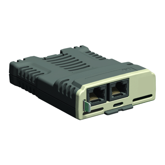
the SI-Ethernet option module has two LEDs mounted on the topside of the module
(Figure 2-1 SI-Ethernet on page 8).
The connection status for the first port (nearest the grounding tab) is indicated by LED
«A», and the second port is indicated by LED «B».
The function of these LEDs are described in table 10.1 LED functionality below.
Table 10.1 LED functionality
LED State
Steady green
Flashing green
10.2
Drive trip display codes
If the Ethernet interface detects an error during operation, it will force a trip on the
drive. However, the trip string displayed on the drive will only indicate which slot
initiated the trip, if the error originated from the onboard Ethernet interface then the
default slot will be 4, however, if the SI-Ethernet option module generated the trip then
the slot number will be the slot number the SI-Ethernet option module is fitted to. The
exact reason for the trip will be indicated in the drive trip code parameters (Pr 0.10.020
and Pr 0.10.070).
Table 10.2 Drive trip indications on page 184 following shows the possible trips that will
be displayed on the drive when a problem is detected or the Ethernet interface initiates
a trip.
SI-Ethernet User Guide
Issue: 1
Description
Off
Ethernet connection not detected.
Ethernet connection detected but no data.
Ethernet communication detected and data flow.
183
-
Contents
-
Table of Contents
-
Bookmarks
Quick Links
User Guide
SI-Ethernet and
Unidrive M —
Onboard Ethernet
Part Number: 0478-0137-03
Issue: 3
Related Manuals for Nidec Unidrive M700
Summary of Contents for Nidec Unidrive M700
-
Page 1
User Guide SI-Ethernet and Unidrive M — Onboard Ethernet Part Number: 0478-0137-03 Issue: 3… -
Page 2
European Chemicals Agency (ECHA) to be a Substance of Very High Concern (SVHC) and is therefore listed by them as a candidate for compulsory authorisation. Further information on our compliance with REACH can be found at: http://www.drive-setup.com/reach Registered Office Nidec Control Techniques Ltd The Gro Newtown Powys SY16 3BE Registered in England and Wales. -
Page 3
All rights reserved. No parts of this guide may be reproduced or transmitted in any form or by any means, electrical or mechanical including photocopying, recording or by an information storage or retrieval system, without permission in writing from the publisher. Copyright © January 2018 Nidec Control Techniques Ltd… -
Page 4: Table Of Contents
Contents Safety information …………6 Warnings, cautions and notes …………..6 Important safety information. Hazards. Competence of designers and installers ……….6 Responsibility ………………6 Compliance with regulations …………..6 Electrical hazards ………………7 Stored electrical charge …………….7 Mechanical hazards …………….7 Access to equipment …………….7 Environmental limits …………….7 1.10 Hazardous environments …………….8 1.11…
-
Page 5
Parameters …………..36 Full parameter descriptions …………..36 Key features and Protocols ……..135 PC/PLC considerations ……………135 Modbus TCP/IP ……………….135 RTMoE (Real Time Motion over Ethernet) ……….144 Non-cyclic data access …………….153 EtherNet/IP ………………158 Web page basics ……………..191 PC Tools Applications ……….198 Unidrive M Connect …………….198 Machine Control Studio ……………198 CTScope …………………199 SyPTPro ………………..199… -
Page 6: Safety Information
Safety information Warnings, cautions and notes A Warning contains information, which is essential for avoiding a safety hazard. WARNING A Caution contains information, which is necessary for avoiding a risk of damage to the product or other equipment. CAUTION A Note contains information, which helps to ensure correct operation of the product. NOTE Important safety information.
-
Page 7: Electrical Hazards
Electrical hazards The voltages used in the drive can cause severe electrical shock and/or burns, and could be lethal. Extreme care is necessary at all times when working with or adjacent to the drive. Hazardous voltage may be present in any of the following locations: •…
-
Page 8: Hazardous Environments
1.10 Hazardous environments The equipment must not be installed in a hazardous environment (i.e. a potentially explosive environment). 1.11 Motor The safety of the motor under variable speed conditions must be ensured. To avoid the risk of physical injury, do not exceed the maximum specified speed of the motor. Low speeds may cause the motor to overheat because the cooling fan becomes less effective, causing a fire hazard.
-
Page 9: Introduction
Unidrive M400 (sizes 2 to 9) • Unidrive M600 (sizes 3 to 11) • Unidrive M700 / M701 / M702 (sizes 3 to 11) Features The following list gives an overview of the functionality available: • Single RJ45 connectivity with support for shielded twisted pair.
-
Page 10: Option Module Identification
Option module identification Figure 2-1 SI-Ethernet Link LEDs Earth connection The SI-Ethernet can be identified by: 1. The label located on the topside of the option module. 2. The color coding across the front of the option module. SI-Ethernet being beige. Figure 2-2 SI-Ethernet label SI-Ethernet 82400000017900…
-
Page 11: Factory Fit Ethernet Interface Identification
Factory fit Ethernet interface identification As standard, the Unidrive M700 and Unidrive M702 variants are fitted with an Ethernet interface and the Unidrive M701 is fitted with the EIA-485 serial communications interface. Care must be taken to ensure the correct interface is fitted before a connection is made to the drive, failure to ensure this may result in damage to the interface and/or communication device.
-
Page 12: Mechanical Installation
Mechanical installation Before installing or removing an option module from any drive, ensure the AC supply has been disconnected for at least 10 minutes and refer to Chapter 1 Safety information on page 6. If using a DC bus supply ensure this is fully discharged before working on any drive or option module.
-
Page 13
Figure 3-2 Installation of an SI option module on Unidrive M200 to M400 (sizes 5 to 9) • Place the option module onto the drive as shown in (2) until the module clicks into place. The terminal cover on the drive holds the option module in place, so this must be put back on. Figure 3-3 Installation of an SI option module on Unidrive M600 to M702 •… -
Page 14: Electrical Installation
Electrical installation SI-Ethernet module information SI-Ethernet provides two standard RJ45 UTP/STP (Un-shielded/Shielded Twisted Pair) connections to a 100 Mbs Ethernet system. In addition to the RJ45 connectors, a grounding tag is supplied for supplementary bonding. SI-Ethernet provides 2 diagnostic LEDs for status and information purposes located on the module topside.
-
Page 15: Cable Shield Connections
Cable shield connections Standard Ethernet UTP or STP cables do not require supplementary grounding. Cable It is recommended that a minimum specification of CAT5e is installed on new installations, as this gives a good cost/performance ratio. If you are using existing cabling, this may limit the maximum data rate depending on the cable ratings.
-
Page 16
Figure 4-3 Typical network topologies SI-Ethernet User Guide Issue: 3… -
Page 17: Getting Started
Getting started Network design considerations Ethernet is an open system allowing many different vendors to design and supply equipment. When designing an industrial network you must carefully consider the topology and data traffic on the network to avoid potential problems. To avoid bandwidth issues it is recommended that the control network is logically separate from any other network.
-
Page 18: Class Types
Class types IP addresses are grouped into ranges called classes, each class has a specific set of addresses and has a typical situation where it is used. When selecting the class of IP address required, consideration must be given to how many subnets you need, how many hosts are required and if you will need a public (worldwide) or a private (local) addressing scheme.
-
Page 19: Dhcp Considerations
5.6.1 The IP address The IP address is made up from four 8 bit decimal numbers (octets) and is written as follows: w.x.y.z for example192.168.0.1 (class c) 5.6.2 The subnet mask The subnet mask defines what part of the address constitutes the subnet within the IP address and what part of the address constitutes the host address.
-
Page 20: Basic Principles Of Routing
5.7.2 Using DHCP If DHCP is used, it is recommended that the allocated IP address is bound to the MAC address of the Ethernet interface, this strategy prevents the IP address changing on the Ethernet interface. Any leased addresses should be leased permanently to prevent IP address changes. If the SI-Ethernet module is configured to use DHCP and the module requires NOTE exchanging, the new SI-Ethernet module will have a different MAC address and hence…
-
Page 21: Set-Up Flow Chart
Set-up flow chart Start Connect all drives PING all drives together using from a command See Chapter 4 See Chapter 5 approved cable / prompt to test connectors / connections switches Ensure each drive Save module See Chapter 4 See Chapter 5 Is correctly settings on drive.
-
Page 22: Single Line Parameter Descriptions
5.10 Single line parameter descriptions Table 5-3 lists the coding used for the parameter type in the subsequent parameter description tables. Table 5-3 Parameter type coding Read / Date Time RO Read-only Bit Txt Text string Date Time Write parameter parameter parameter Character…
-
Page 23
5.10.2 Menu 0 — Ethernet set-up (MM.ppp) Table 5-5 Menu 0 parameters Size Parameter Range Default Access (Bits) S.00.000 Parameter mm.000 0 to 65535 S.00.001 Module ID 0 to 65535 00.00.00.00 to S.00.002 Software Version 99.99.99.99 S.00.003 Hardware Version 0.00 to 99.99 S.00.004 Serial Number LS 0 to 99999999… -
Page 24
5.10.3 Menu 2 — Ethernet Configuration Table 5-7 Menu 2 parameters Size Parameter Range Default Access (Bits) S.02.000 Parameter mm.000 0 to 65535 S.02.003 Network Status 0 to 5 S.02.004 Network Message Count 0 to 65535 msg/s S.02.005 DHCP Enable 0 (Off) to 1 (On) 1 (On) 0.0.0.0 to… -
Page 25
5.10.5 Menu 10 — Easy Mode Cyclic Data Table 5-9 Menu 10 parameters Size Parameter Range Default Access (Bits) S.10.000 Parameter mm.000 0 to 65535 S.10.001 Easy Mode Enable 0 (Off) to 1 (On) 1 (On) S.10.002 Easy Mode Reset 0 (Off) to 1 (On) 0 (Off) S.10.003 Easy Mode Default… -
Page 26
Size Parameter Range Default Access (Bits) S.10.040 Rx1 Link Profile 0 (Std) to 1 (Sync) 0 (Std) S.10.041 Rx1 Link Number 0 to 255 0 (0.00.000) to S.10.042 Rx1 Destination Parameter 0 (0.00.000) 499999 (4.99.999) S.10.043 Rx1 Parameter Count 0 to 10 0 (Direct) to S.10.044 Rx1 Source Type 0 (Direct) -
Page 27
5.10.6 Menu 11 — Synchronization Table 5-10 Menu 11 parameters Size Parameter Range Default Access (Bits) S.11.000 Parameter mm.000 0 to 65535 S.11.001 Preferred Sync Master 0 to 4 S.11.002 Master Clock Domain 0 to 3 0000000000000000 to S.11.005 Grandmaster MAC Address FFFFFFFFFFFFFFFF -2147483648 ns to S.11.006… -
Page 28
5.10.7 Menu 15 — Modbus Table 5-11 Menu 15 parameters Size Parameter Range Default Access (Bits) S.15.000 Parameter mm.000 0 to 65535 S.15.001 Enable 0 (Off) to 1 (On) 1 (On) S.15.002 Reset 0 (Off) to 1 (On) 0 (Off) S.15.003 Default 0 (Off) to 1 (On) -
Page 29
5.10.8 Menu 20 — EtherNet/IP Setup Table 5-12 Menu 20 parameters Size Parameter Range Default Access (Bits) S.20.000 Parameter mm.000 0 to 65535 S.20.001 Enable EtherNet/IP 0 (Off) to 1 (On) 1 (On) S.20.002 Reset 0 (Off) to 1 (On) 0 (Off) S.20.003 Default… -
Page 30
5.10.9 Menu 21 — EtherNet/IP In Mappings Table 5-13 Menu 21 parameters Size Parameter Range Default Access (Bits) S.21.000 Parameter mm.000 0 to 65535 0 (0.00.000) to S.21.001 Input mapping parameter 1 10040 (0.10.040) 499999 (4.99.999) 0 (0.00.000) to S.21.002 Input mapping parameter 2 2001 (0.02.001) 499999 (4.99.999) -
Page 31
Size Parameter Range Default Access (Bits) 0 (0.00.000) to S.21.025 Input mapping parameter 25 0 (0.00.000) 499999 (4.99.999) 0 (0.00.000) to S.21.026 Input mapping parameter 26 0 (0.00.000) 499999 (4.99.999) 0 (0.00.000) to S.21.027 Input mapping parameter 27 0 (0.00.000) 499999 (4.99.999) 0 (0.00.000) to S.21.028… -
Page 32
5.10.10 Menu 22 — EtherNet/IP Out Mappings Table 5-14 Menu 22 parameters Size Parameter Range Default Access (Bits) S.22.000 Parameter mm.000 0 to 65535 0 (0.00.000) to S.22.001 Output mapping parameter 1 6042 (0.06.042) 499999 (4.99.999) 0 (0.00.000) to S.22.002 Output mapping parameter 2 1021 (0.01.021) 499999 (4.99.999) -
Page 33
Size Parameter Range Default Access (Bits) 0 (0.00.000) to S.22.025 Output mapping parameter 25 0 (0.00.000) 499999 (4.99.999) 0 (0.00.000) to S.22.026 Output mapping parameter 26 0 (0.00.000) 499999 (4.99.999) 0 (0.00.000) to S.22.027 Output mapping parameter 27 0 (0.00.000) 499999 (4.99.999) 0 (0.00.000) to S.22.028… -
Page 34
5.10.11 Menu 23 — EtherNet/IP Fault Values Table 5-15 Menu 23 parameters Size Parameter Range Default Access (Bits) S.23.000 Parameter mm.000 0 to 65535 -2147483648 to S.23.001 Output fault value 1 2147483647 -2147483648 to S.23.002 Output fault value 2 2147483647 -2147483648 to S.23.003 Output fault value 3… -
Page 35
Size Parameter Range Default Access (Bits) -2147483648 to S.23.025 Output fault value 25 2147483647 -2147483648 to S.23.026 Output fault value 26 2147483647 -2147483648 to S.23.027 Output fault value 27 2147483647 -2147483648 to S.23.028 Output fault value 28 2147483647 -2147483648 to S.23.029 Output fault value 29 2147483647… -
Page 36: Parameters
Parameters The Ethernet interface holds two parameter databases; the Ethernet interface internal parameter database and the host drive’s parameter database. The Ethernet interface internal parameters can be accessed from the drive’s keypad, a user program in a MCi200/MCi210 option module, PC Tools applications software or a module in another slot of the drive.
-
Page 37
S.00.003 Hardware Version Minimum 00.00 Maximum 99.99 Default None Units None Type 16 Bit Volatile Update Rate Written on module initialization Display Format None Decimal Places Coding RO, ND, NC, PT The hardware version of the option module is in the format of xx.yy. S.00.004 Serial Number LS Minimum… -
Page 38
Value Text Description Bootldr — Update The bootloader is performing a flash update. Bootldr — Idle The bootloader is idle. Initializing Module is currently initializing. Module has initialized and has found no errors. Config A configuration error has been detected. An error has occurred preventing the module from running Error correctly. -
Page 39
S.00.009 Active Alarm Bits 65535 Minimum Maximum (Display:0000000000000000) (Display:1111111111111111) Default Units None (Display:0000000000000000) Type 16 Bit Volatile Update Rate Background Display Decimal Binary Format Places Coding RO, NC, BU Alarm User Program eCMP Modbus Ethernet/IP Reserved Filesystem Too Hot S.00.010 Active IP Address -2147483648 2147483647… -
Page 40
6.1.2 Menu 2 — Ethernet configuration S.02.003 Network Status Minimum Maximum (Display: Initializing) (Display: Active) Default None Units None Type 8 Bit Volatile Update Rate Written every second Display Format None Decimal Places Coding RO, Txt, ND, NC, PT, BU Value Text Description… -
Page 41
When DHCP is enabled, the following parameters will become read-only immediately (no reset required): • IP Address (S.02.006) • Subnet Mask (S.02.007) • Default Gateway (S.02.008) • Primary DNS (S.02.009) • Secondary DNS (S.02.010) S.02.006 IP Address 4294967295 Minimum Maximum (Display: 0.0.0.0) (Display:255.255.255.255) 3232235876… -
Page 42
S.02.008 Default Gateway 4294967295 Minimum Maximum (Display: 0.0.0.0) (Display:255.255.255.255) 3232236030 Default Units None (Display:192.168.1.254) DHCP enabled: write on event; Type 32 Bit User Save Update Rate DHCP disabled: read on reset Display Format IP Address Decimal Places Coding RW, BU Controls and displays the default gateway of the module. -
Page 43
S.02.010 Secondary DNS 4294967295 Minimum Maximum (Display: 0.0.0.0) (Display:255.255.255.255) Default Units None (Display: 0.0.0.0) DHCP enabled: Type 32 Bit User Save Update Rate write on event; DHCP disabled: read on reset Display Format IP Address Decimal Places Coding RW, BU The module can use this IP address when it wishes to resolve the IP address for a domain name. -
Page 44
S.02.021 Web Server Enable Minimum Maximum (Display: Off) (Display: On) Default Units None (Display: On) Type 1 Bit User Save Update Rate Background read Display Format None Decimal Places Coding RW, BU Controls the running of the web server on the module. The web server functionality is available in firmware version V01.06.00.22 and onwards. -
Page 45
S.02.025 Gateway Mode Minimum Maximum (Display: Switch) (Display: Strict Gateway) Default Units None (Display: Switch) Type 8 Bit User Save Update Rate Read on module reset Display Format None Decimal Places Coding RW, Txt, BU Value Text Switch Gateway Strict Gateway Specifies the operation mode of the gateway. -
Page 46
S.02.030 VLAN Enable Minimum Maximum (Display: Off) (Display: On) Default Units (Display: Off) Type 1 Bit User Save Update Rate Read on module reset Display Format None Decimal Places Coding Controls whether the module will use VLAN tagging. When used in conjunction with Drive VLAN ID (S.02.031) network traffic from the interface will be tagged with the chosen VLAN identifier. -
Page 47
the parameter scaling within the PLC or controller due to differences in the number of decimal places of parameters between the Unidrive SP and Unidrive M range of drives. S.02.035 Non cyclic enable Minimum Maximum (Display: Off) (Display: On) Default Units None (Display: Off) -
Page 48
S.MM.PPP : Status and Command This parameter contains the command code (bits b7 to b0) and status (bits b15 to b8) information. Possible values for Status are: Value Meaning Description IDLE Idle. READY The parameter channel is ready to take command. PROCESSING Processing the command. -
Page 49
The following table list the possible error codes: Value Meaning Description Address Type The addressing type is not supported. Timeout A timeout occurred trying to access the specified item. Access Denied The requesting device does not have sufficient access rights. Does not exist The specified item does not exist. -
Page 50
S.09.002 Cyclic Rx Links Free Minimum Maximum Default None Units None Type 8 Bit Volatile Update Rate Background write Display Format None Decimal Places Coding RO, ND, NC, PT, BU The number of available receive cyclic links. S.09.003 Fieldbus Links Free Minimum Maximum Default… -
Page 51
S.09.020 Sync Task Worst % Free Minimum Maximum Default None Units Type 8 Bit Volatile Update Rate Background write Display Format None Decimal Places Coding RO, ND, NC, PT, BU Worst case free resource of the synchronous task. S.09.030 PCB Temperature Minimum -128 Maximum… -
Page 52
S.10.001 Easy Mode Enable Minimum Maximum (Display: Off) (Display: On) Default Units None (Display: On) Type 1 Bit User Save Update Rate Background read Display Format None Decimal Places Coding RW, BU This parameter is used to enable or disable the Easy Mode protocol interface. S.10.002 Easy Mode Reset Minimum… -
Page 53
S.10.005 Configuration Valid Minimum Maximum (Display: Off) (Display: On) Default None Units None Type 1 Bit Volatile Update Rate Read on reset Display Format None Decimal Places Coding RO, PT, NC, ND If the active configuration identified by Active Configuration (S.10.007) has no configuration errors then the configuration is valid and this parameter will be set to 1 (On). -
Page 54
A receive link timeout will cause this parameter to become cleared (Off) until a new message is received. A single data late event will cause this parameter to be Off until the next cyclic message is received on time. If low latency reactions to timeout and data late events are required then appropriate actions should be configured for the relevant links, see Rx1 Timeout Action (S.10.046), Rx2 Timeout Action (S.10.056) or Rx3 Timeout Action (S.10.066) for further details. -
Page 55
S.10.009 Data Late Count Minimum Maximum 65535 Default None Units None Type 16 Bit Volatile Update Rate 1 ms Display Format None Decimal Places Coding RO, PT, NC, ND, BU This parameter displays the total number of receive data late events; each data late event will increment the count by 1. -
Page 56
S.10.012 Tx1 Source Parameter 499999 Minimum Maximum (Display:0.00.000) (Display: 4.99.999) Default Units None (Display:0.00.000) Type 32 Bit User Save Update Rate Read on reset Display Format Slot Menu Param Decimal Places Coding RW, PT, BU This parameter sets the source parameter for the Tx1 link. S.10.013 Tx1 Parameter Count Minimum… -
Page 57
S.10.014 Tx1 Transmission Type Minimum Maximum (Display: Unicast (Display: Multicast10) Default Units None (Display: Unicast Type 8 Bit User Save Update Rate Read on reset Display Format None Decimal Places Coding RW, Txt, BU Value Text Description Unicast Link is unicast to the IP address specified Broadcast Link is broadcast (255.255.255.255) Multicast1… -
Page 58
S.10.016 Tx1 Message Rate Minimum Maximum Default Units Type 8 Bit User Save Update Rate Read on reset Display Format None Decimal Places Coding RW, BU Defines, in milliseconds, the rate at which Tx1 Link will be transmitted. A value of zero disables the transmission of data. -
Page 59
Value Text Description Read only param The mapped parameter is read only Msg mismatch Link number and direction do not match Msg too long Resulting message is too long Attrib NA Attribute not available Attrib RO Attribute is read only Attrib missing Attribute is missing Timeout… -
Page 60
S.10.021 Tx2 Link Number Minimum Maximum Default Units None Type 8 Bit User Save Update Rate Read on reset Display Format None Decimal Places Coding RW, BU This parameter is used to set the link number (1 to 255) for the Tx2 link. S.10.022 Tx2 Source Parameter 499999… -
Page 61
S.10.024 Tx2 Transmission Type Minimum Maximum (Display: Unicast) (Display: Multicast10) Default Units None (Display: Unicast) Type 8 Bit User Save Update Rate Read on reset Display Format None Decimal Places Coding RW, Txt, BU Value Text Description Unicast Link is unicast to the IP address specified Broadcast Link is broadcast (255.255.255.255) Multicast1… -
Page 62
S.10.026 Tx2 Message Rate Minimum Maximum Default Units Type 8 Bit User Save Update Rate Read on reset Display Format None Decimal Places Coding RW, BU Defines, in milliseconds, the rate at which Tx2 Link will be transmitted. A value of zero disables the transmission of data. -
Page 63
Value Text Description Read only param The mapped parameter is read only Msg mismatch Link number and direction do not match Msg too long Resulting message is too long Attrib NA Attribute not available Attrib RO Attribute is read only Attrib missing Attribute is missing Timeout… -
Page 64
S.10.031 Tx3 Link Number Minimum Maximum Default Units None Type 8 Bit User Save Update Rate Read on reset Display Format None Decimal Places Coding RW, BU This parameter is used to set the link number (1 to 255) for the Tx3 link. S.10.032 Tx3 Source Parameter 499999… -
Page 65
S.10.034 Tx3 Transmission Type Minimum Maximum (Display: Unicast) (Display: Multicast10) Default Units None (Display: Unicast) Type 8 Bit User Save Update Rate Read on reset Display Format None Decimal Places Coding RW, Txt, BU Value Text Description Unicast Link is unicast to the IP address specified Broadcast Link is broadcast (255.255.255.255) Multicast1… -
Page 66
S.10.036 Tx3 Message Rate Minimum Maximum Default Units Type 8 Bit User Save Update Rate Read on reset Display Format None Decimal Places Coding RW, BU Defines, in milliseconds, the rate at which Tx3 Link will be transmitted. A value of zero disables the transmission of data. -
Page 67
Value Text Description Invalid mapping The mapped parameter does not exist Read only param The mapped parameter is read only Msg mismatch Link number and direction do not match Msg too long Resulting message is too long Attrib NA Attribute not available Attrib RO Attribute is read only Attrib missing… -
Page 68
S.10.041 Rx1 Link Number Minimum Maximum Default Units None Type 8 Bit User Save Update Rate Read on reset Display Format None Decimal Places Coding RW, BU This parameter is used to set the link number (1 to 255) for the Rx1 link. S.10.042 Rx1 Destination Parameter 499999… -
Page 69
S.10.044 Rx1 Source Type Minimum Maximum (Display: Unicast) (Display: Multicast10) Default Units None (Display: Unicast) Type 8 Bit User Save Update Rate Read on reset Display Format None Decimal Places Coding RW, Txt, BU Value Text Description Unicast Link is unicast to the IP address specified Broadcast Link is broadcast (255.255.255.255) Multicast1… -
Page 70
S.10.046 Rx1 Timeout Action Minimum Maximum (Display: Trip) (Display: Hold last) Default Units None (Display: Trip) Type 8 Bit User Save Update Rate Read on reset Display Format None Decimal Places Coding RW, Txt, BU Value Text Description Trip Trip drive with Slx.Er and sub-trip code 106 (Cyclic Timeout) Clear output PLC output parameters will have their values set to zero Hold last… -
Page 71
S.10.048 Rx1 Timeout Event Type Minimum Maximum (Display: No Event) (Display: Event3) Default Units None (Display: No Event) Type 8 Bit User save Update Rate Read on reset Display Format None Decimal Places Coding RW, Txt, BU Value Text Description No Event No event Event… -
Page 72
Value Text Description Invalid DST IP Destination IP address is invalid Sync link does not support mappings to other option SYNC unsupported parameters MEC offset Incorrect MEC offset Invalid tx rate Tx rate must be a factor of 1 second The number of mapping items exceeds the range Too many mapping supported… -
Page 73
S.10.050 Rx2 Link Profile Minimum Maximum (Display: Sync) (Display: Std) Default Units None (Display: Std) Type 8 Bit User Save Update Rate Read on reset Display Format None Decimal Places Coding RW, Txt Value Text Description Standard link Sync Synchronized link Used to select Rx2 as a standard or synchronous cyclic link. -
Page 74
S.10.054 Rx2 Source Type Minimum Maximum (Display: Unicast) (Display: Multicast10) Default Units None (Display: Unicast) Type 8 Bit User Save Update Rate Read on reset Display Format None Decimal Places Coding RW, Txt, BU Value Text Description Unicast Link is unicast to the IP address specified Broadcast Link is broadcast (255.255.255.255) Multicast1… -
Page 75
S.10.056 Rx2 Timeout Action Minimum Maximum (Display: Trip) (Display: Hold last) Default Units None (Display: Trip) Type 8 Bit User save Update Rate Read on reset Display Format None Decimal Places Coding RW, Txt, BU Value Text Description Trip Trip drive with Slx.Er and sub-trip code 106 (Cyclic Timeout) Clear output PLC output parameters will have their values set to zero Hold last… -
Page 76
S.10.058 Rx2 Timeout Event Type Minimum Maximum (Display: No Event) (Display: Event3) Default Units None (Display: No Event) Type 8 Bit User save Update Rate Read on reset Display Format None Decimal Places Coding RW, Txt, BU Value Text Description No Event No event Event… -
Page 77
Value Text Description Invalid DST IP Destination IP address is invalid Sync link does not support mappings to other option SYNC unsupported parameters MEC offset Incorrect MEC offset Invalid tx rate Tx rate must be a factor of 1 second The number of mapping items exceeds the range Too many mapping supported… -
Page 78
S.10.060 Rx3 Link Profile Minimum Maximum (Display: Std) (Display: Sync) Default Units None (Display: Std) Type 8 Bit User Save Update Rate Read on reset Display Format None Decimal Places Coding RW, Txt Value Text Description Standard link Sync Synchronized link Used to select Rx3 as a standard or synchronous cyclic link. -
Page 79
S.10.064 Rx3 Source Type Minimum Maximum (Display: Unicast) (Display: Multicast10) Default Units None (Display: Unicast) Type 8 Bit User Save Update Rate Read on reset Display Format None Decimal Places Coding RW, Txt, BU Value Text Description Unicast Link is unicast to the IP address specified Broadcast Link is broadcast (255.255.255.255) Multicast1… -
Page 80
S.10.066 Rx3 Timeout Action Minimum Maximum (Display: Trip) (Display: Hold last) Default Units None (Display: Trip) Type 8 Bit User Save Update Rate Read on reset Display Format None Decimal Places Coding RW, Txt, BU Value Text Description Trip Trip drive with Slx.Er and sub-trip code 106 (Cyclic Timeout) Clear output PLC output parameters will have their values set to zero Hold last… -
Page 81
S.10.068 Rx3 Timeout Event Type Minimum Maximum (Display: No Event) (Display: Event3) Default Units None (Display: No Event) Type 8 Bit User save Update Rate Read on reset Display Format None Decimal Places Coding RW, Txt, BU Value Text Description No Event No event Event… -
Page 82
Value Text Description Sync link does not support mappings to other option SYNC unsupported parameters MEC offset Incorrect MEC offset Invalid tx rate Tx rate must be a factor of 1 second The number of mapping items exceeds the range Too many mapping supported Link busy… -
Page 83
6.1.5 Menu 11 – Synchronization S.11.001 Preferred Sync Master Minimum Maximum Default Units None Type 8 Bit User Save Update Rate Read on reset Display Format None Decimal Places Coding RW, BU This Ethernet interface will be preferred as the grandmaster over others with higher preferred values or none specified. -
Page 84
S.11.007 Sync Jitter Threshold Minimum Maximum 1000000 Default 1000 Units Type 32 Bit User Save Update Rate Read on reset Display Format None Decimal Places Coding RW, BU Sets the application tolerable clock jitter in ns from the grandmaster. If Sync Jitter From Grandmaster (S.11.006) is within the tolerance the local clock is used and Module Synchronised Flag (S.11.008) is set to 1 and synchronized cyclic data links will be processed. -
Page 85
S.11.011 PTP Time 235959 Minimum Maximum (Display: 00:00:00) (Display: 23:59:59) Default None Units None Type 32 Bit Volatile Update Rate Written every 500 ms Display Format Time Decimal Places Coding RO, ND, NC, PT, BU This parameter displays the current time. If the module has no time source it will display the time based on its power-up time. -
Page 86
S.11.017 In sync window length Minimum Maximum Default Units Seconds Type 8 Bit User Save Update Rate Read on reset Display Format None Decimal Places Coding RW, BU Duration that the jitter (Synchronisation Jitter From Grandmaster (S.11.006)) must be below the jitter threshold for before the in sync flag (Module Synchronised Flag (S.11.008)) is set. -
Page 87
S.11.030 Easy Mode Maximum Network Delay Minimum Maximum Default Units Type 8 Bit User Save Update Rate Read on reset Display Format None Decimal Places Coding RW, BU This parameter defines the allowable network delay (in milliseconds) for the Easy Mode synchronous transmit cyclic links to arrive at their destination. -
Page 88
Rx1 link. This feature is not yet implemented. NOTE S.11.042 Rx1 Late Sync Frame Event Minimum Maximum (Display: No Event) (Display: Event3) Default Units None (Display: No Event) Type 8 Bit User Save Update Rate Read on reset Display Format None Decimal Places Coding… -
Page 89
S.11.051 Rx2 Late Sync Frame Dest Minimum Maximum (Display: This slot) (Display: Slot 4) Default Units None (Display: This slot) Type 8 Bit User Save Update Rate Read on reset Display Format None Decimal Places Coding RW, Txt, BU Value Text Description This slot… -
Page 90
S.11.060 Rx3 Late Sync Frame Action Minimum Maximum (Display: Trip) (Display: Use) Default Units None (Display: Trip) Type 8 Bit User Save Update Rate Read on reset Display Format None Decimal Places Coding RW, Txt, BU Value Text Description Trip Trip drive with Slx.Er and sub-trip code 107 Do not use The data is ignored… -
Page 91
S.11.062 Rx3 Late Sync Frame Event Minimum Maximum (Display: No Event) (Display: Event3) Default Units None (Display: No Event) Type 8 Bit User Save Update Rate Read on reset Display Format None Decimal Places Coding RW, Txt, BU Value Text Description No Event No event… -
Page 92
S.15.003 Default Minimum Maximum (Display: Off) (Display: On) Default Units None (Display: Off) On module reset, protocol Type 1 Bit Volatile Update Rate interface reset or protocol enable Display Format None Decimal Places Coding RW, NC This parameter allows the Modbus protocol to be defaulted to factory settings. This includes all of the protocol features, configuration, mappings and stored objects. -
Page 93
S.15.006 Maximum Connections Minimum Maximum Default Units None Module reset, Modbus Type 8 Bit User Save Update Rate interface reset or Modbus interface enable Display Format None Decimal Places Coding RW, BU This parameter permits the user to specify the total number of connections that one or more clients can open with the module at any one time. -
Page 94
S.15.009 Modbus Timeout Minimum Maximum 10000 Default Units Module reset, Modbus Type 16 Bit User Save Update Rate interface reset or Modbus interface enable Display Format None Decimal Places Coding RW, BU This parameter defines the time period in which the Modbus server must receive a message before any specified action (as defined in Modbus Timeout Action (S.15.010)) is performed. -
Page 95
S.15.011 Modbus Timeout Event Dest Minimum Maximum (Display: This slot) (Display: Slot 4) Default Units None (Display: This slot) Module reset, Modbus Type 8 Bit User Save Update Rate interface reset or Modbus interface enable Display Format None Decimal Places Coding RW, Txt, BU Value… -
Page 96
must specify an appropriate consumer (slot option) of the event. This feature is not yet implemented. NOTE S.15.013 Modbus Register Addressing Mode Minimum Maximum (Display: Standard) (Display: Modified) Default Units None (Display: Standard) Module reset, Modbus Type 8 Bit User Save Update Rate interface reset or Modbus interface enable… -
Page 97
S.15.021 Priority Connection 2 4294967295 Minimum Maximum (Display: 0.0.0.0) (Display: 255.255.255.255) Default Units None (Display: 0.0.0.0) Module reset, Modbus Type 32 Bit User Save Update Rate interface reset or Modbus interface enable Display Format IP Address Decimal Places Coding RW, BU This parameter specifies an IP address for priority connection 2. -
Page 98
6.1.7 Menu 20 – EtherNet/IP Set-up The Ethernet interface supports the EtherNet/IP protocol and conforms to the EtherNet/IP adaptation of the Common Industrial Protocol (CIP) Specification. This is the same upper-layer protocol and object model as used in DeviceNet. The Ethernet interface will operate as a slave device and the following functionality is supported. •… -
Page 99
S.20.001 Enable EtherNet/IP Minimum Maximum (Display: Off) (Display: On) Default Units None (Display: On) Type 1 Bit User Save Update Rate Background read Display Format None Decimal Places Coding RW, BU This parameter is used to enable or disable EtherNet/IP slave functionality. If either Input Assembly Object Size (S.20.020) or Output Assembly Object Size NOTE (S.20.021) is a non zero value then the available mappings will still be consumed even… -
Page 100
S.20.004 Configuration error Minimum Maximum (Display: No error) (Display: Out cons trig pr) Default None Units None Type 8 Bit Volatile Update Rate Background Display Format None Decimal Places Coding RO, Txt, ND, NC, PT, BU Value Text Description No error No error RPI event dst RPI timeout event destination not valid… -
Page 101
S.20.011 RPI timeout action Minimum Maximum (Display: Trip) (Display: No Action) Default Units None (Display: Hold last) Module reset, EtherNet/IP Type 8 Bit User Save Update Rate interface reset or EtherNet/IP interface enable Display Format None Decimal Places Coding RW, Txt, BU Value Text Description… -
Page 102
S.20.012 RPI Timeout Event Dest Minimum Maximum (Display: This slot) (Display: Slot 4) Default Units None (Display: This slot) Module reset, EtherNet/IP Type 8 Bit User Save Update Rate interface reset or EtherNet/IP interface enable Display Format None Decimal Places Coding RW, Txt, BU Value… -
Page 103
This feature is not yet implemented. NOTE S.20.015 PLC idle action Minimum Maximum (Display: Trip) (Display: No Action) Default Units None (Display: No Action) Module reset, EtherNet/IP Type 8 Bit User Save Update Rate interface reset or EtherNet/IP interface enable Display Format None Decimal Places… -
Page 104
S.20.017 PLC idle event type Minimum Maximum (Display: No event) (Display: Trigger Event 4) Default Units None (Display: No event) Module reset, EtherNet/IP Type 8 Bit User Save Update Rate interface reset or EtherNet/IP interface enable Display Format None Decimal Places Coding RW, Txt, BU Value… -
Page 105
S.20.019 Active output assembly object Minimum Maximum (Display: 101-PrimaryO) (Display: 23-ExtSpdTqCtrlO) Default Units None (Display: 101-PrimaryO) Module reset, EtherNet/IP Type 8 Bit Volatile Update Rate interface reset or EtherNet/IP interface enable Display Format None Decimal Places Coding RO, Txt, NC, ND, PT, BU Value Text Description… -
Page 106
S.20.024 Input Assembly Object Process Time Minimum Maximum 65535 Default None Units Type 16 Bit Volatile Update Rate Background Display Format None Decimal Places Coding RO, ND, NC, PT, BU This is the time between getting the input value from the master and it being sent successfully to the drive. -
Page 107
S.20.027 In Consistency Trigger Param 499999 Minimum Maximum (Display: 0.00.000) (Display: 4.99.999) Default Units None (Display: 0.00.000) Module reset, EtherNet/IP Type 32 Bit User Save Update Rate interface reset or EtherNet/IP interface enable Display Format Slot Menu Param Decimal Places Coding RW, BU This parameter specifies the parameter to use for triggering input assembly object consistency. -
Page 108
S.20.029 Out Consistency Trigger Param 499999 Minimum Maximum (Display: 0.00.000) (Display: 4.99.999) Default Units None (Display: 0.00.000) Module reset, EtherNet/IP Type 32 Bit User Save Update Rate interface reset or EtherNet/IP interface enable Display Format Slot Menu Param Decimal Places Coding RW, BU This parameter specifies the parameter to use for triggering output assembly object consistency. -
Page 109
S.20.032 Custom product revision code Minimum Maximum 65535 Default Units None Module reset, EtherNet/IP Type 16 Bit User Save Update Rate interface reset or EtherNet/IP interface enable Display Format None Decimal Places Coding RW, BU This parameter defines a custom product revision value which is used to identify the product on the network. -
Page 110
S.20.040 Type of Motor 1 Minimum Maximum (Display: 2-FC DC) (Display: 10-Trap PM BL) Default Units None (Display: 7-SCI) Type 8 Bit User Save Update Rate Reset Display Format None Decimal Places Coding RO, Txt, PT, BU Value Text Description 2-FC DC FC DC Motor 6-WRI… -
Page 111
6.1.8 Menu 21 – EtherNet/IP In Mappings This menu contains the parameters used to define the source parameters for data that will be transmitted to the PLC. S.21.001 Input mapping parameter 1 499999 Minimum Maximum (Display: 0.00.000) (Display: 4.99.999) 10040 Default Units None… -
Page 112
S.21.004 Input mapping parameter 4 499999 Minimum Maximum (Display: 0.00.000) (Display: 4.99.999) Default Units None (Display: 0.00.000) Module reset, EtherNet/IP Type 32 Bit User Save Update Rate interface reset or EtherNet/IP interface enable Display Format Slot Menu Param Decimal Places Coding RW, PT, BU S.21.005… -
Page 113
S.21.008 Input mapping parameter 8 499999 Minimum Maximum (Display: 0.00.000) (Display: 4.99.999) Default Units None (Display: 0.00.000) Module reset, EtherNet/IP Type 32 Bit User Save Update Rate interface reset or EtherNet/IP interface enable Display Format Slot Menu Param Decimal Places Coding RW, PT, BU S.21.009… -
Page 114
S.21.012 Input mapping parameter 12 499999 Minimum Maximum (Display: 0.00.000) (Display: 4.99.999) Default Units None (Display: 0.00.000) Module reset, EtherNet/IP Type 32 Bit User Save Update Rate interface reset or EtherNet/IP interface enable Display Format Slot Menu Param Decimal Places Coding RW, PT, BU S.21.013… -
Page 115
S.21.016 Input mapping parameter 16 499999 Minimum Maximum (Display: 0.00.000) (Display: 4.99.999) Default Units None (Display: 0.00.000) Module reset, EtherNet/IP Type 32 Bit User Save Update Rate interface reset or EtherNet/IP interface enable Display Format Slot Menu Param Decimal Places Coding RW, PT, BU S.21.017… -
Page 116
S.21.020 Input mapping parameter 20 499999 Minimum Maximum (Display: 0.00.000) (Display: 4.99.999) Default Units None (Display: 0.00.000) Module reset, EtherNet/IP Type 32 Bit User Save Update Rate interface reset or EtherNet/IP interface enable Display Format Slot Menu Param Decimal Places Coding RW, PT, BU S.21.021… -
Page 117
S.21.024 Input mapping parameter 24 499999 Minimum Maximum (Display: 0.00.000) (Display: 4.99.999) Default Units None (Display: 0.00.000) Module reset, EtherNet/IP Type 32 Bit User Save Update Rate interface reset or EtherNet/IP interface enable Display Format Slot Menu Param Decimal Places Coding RW, PT, BU S.21.025… -
Page 118
S.21.028 Input mapping parameter 28 499999 Minimum Maximum (Display: 0.00.000) (Display: 4.99.999) Default Units None (Display: 0.00.000) Module reset, EtherNet/IP Type 32 Bit User Save Update Rate interface reset or EtherNet/IP interface enable Display Format Slot Menu Param Decimal Places Coding RW, PT, BU S.21.029… -
Page 119
S.21.032 Input mapping parameter 32 499999 Minimum Maximum (Display: 0.00.000) (Display: 4.99.999) Default Units None (Display: 0.00.000) Module reset, EtherNet/IP Type 32 Bit User Save Update Rate interface reset or EtherNet/IP interface enable Display Format Slot Menu Param Decimal Places Coding RW, PT, BU 6.1.9… -
Page 120
S.22.003 Output mapping parameter 3 499999 Minimum Maximum (Display: 0.00.000) (Display: 4.99.999) Default Units None (Display: 0.00.000) Module reset, EtherNet/IP Type 32 Bit User Save Update Rate interface reset or EtherNet/IP interface enable Display Format Slot Menu Param Decimal Places Coding RW, PT, BU S.22.004… -
Page 121
S.22.007 Output mapping parameter 7 499999 Minimum Maximum (Display: 0.00.000) (Display: 4.99.999) Default Units None (Display: 0.00.000) Module reset, EtherNet/IP Type 32 Bit User Save Update Rate interface reset or EtherNet/IP interface enable Display Format Slot Menu Param Decimal Places Coding RW, PT, BU S.22.008… -
Page 122
S.22.011 Output mapping parameter 11 499999 Minimum Maximum (Display: 0.00.000) (Display: 4.99.999) Default Units None (Display: 0.00.000) Module reset, EtherNet/IP Type 32 Bit User Save Update Rate interface reset or EtherNet/IP interface enable Display Format Slot Menu Param Decimal Places Coding RW, PT, BU S.22.012… -
Page 123
S.22.015 Output mapping parameter 15 499999 Minimum Maximum (Display: 0.00.000) (Display: 4.99.999) Default Units None (Display: 0.00.000) Module reset, EtherNet/IP Type 32 Bit User Save Update Rate interface reset or EtherNet/IP interface enable Display Format Slot Menu Param Decimal Places Coding RW, PT, BU S.22.016… -
Page 124
S.22.019 Output mapping parameter 19 499999 Minimum Maximum (Display: 0.00.000) (Display: 4.99.999) Default Units None (Display: 0.00.000) Module reset, EtherNet/IP Type 32 Bit User Save Update Rate interface reset or EtherNet/IP interface enable Display Format Slot Menu Param Decimal Places Coding RW, PT, BU S.22.020… -
Page 125
S.22.023 Output mapping parameter 23 499999 Minimum Maximum (Display: 0.00.000) (Display: 4.99.999) Default Units None (Display: 0.00.000) Module reset, EtherNet/IP Type 32 Bit User Save Update Rate interface reset or EtherNet/IP interface enable Display Format Slot Menu Param Decimal Places Coding RW, PT, BU S.22.024… -
Page 126
S.22.027 Output mapping parameter 27 499999 Minimum Maximum (Display: 0.00.000) (Display: 4.99.999) Default Units None (Display: 0.00.000) Module reset, EtherNet/IP Type 32 Bit User Save Update Rate interface reset or EtherNet/IP interface enable Display Format Slot Menu Param Decimal Places Coding RW, PT, BU S.22.028… -
Page 127
S.22.031 Output mapping parameter 31 499999 Minimum Maximum (Display: 0.00.000) (Display: 4.99.999) Default Units None (Display: 0.00.000) Module reset, EtherNet/IP Type 32 Bit User Save Update Rate interface reset or EtherNet/IP interface enable Display Format Slot Menu Param Decimal Places Coding RW, PT, BU S.22.032… -
Page 128
S.23.002 Output fault value 2 Minimum -2147483648 Maximum 2147483647 Default Units Module reset, EtherNet/IP Type 32 Bit User Save Update Rate interface reset or EtherNet/IP interface enable Display Format None Decimal Places Coding RW, PT S.23.003 Output fault value 3 Minimum -2147483648 Maximum… -
Page 129
S.23.007 Output fault value 7 Minimum -2147483648 Maximum 2147483647 Default Units Module reset, EtherNet/IP Type 32 Bit User Save Update Rate interface reset or EtherNet/IP interface enable Display Format None Decimal Places Coding RW, PT S.23.008 Output fault value 8 Minimum -2147483648 Maximum… -
Page 130
S.23.011 Output fault value 11 Minimum -2147483648 Maximum 2147483647 Default Units Module reset, EtherNet/IP Type 32 Bit User Save Update Rate interface reset or EtherNet/IP interface enable Display Format None Decimal Places Coding RW, PT S.23.012 Output fault value 12 Minimum -2147483648 Maximum… -
Page 131
S.23.016 Output fault value 16 Minimum -2147483648 Maximum 2147483647 Default Units Module reset, EtherNet/IP Type 32 Bit User Save Update Rate interface reset or EtherNet/IP interface enable Display Format None Decimal Places Coding RW, PT S.23.017 Output fault value 17 Minimum -2147483648 Maximum… -
Page 132
S.23.021 Output fault value 21 Minimum -2147483648 Maximum 2147483647 Default Units Module reset, EtherNet/IP Type 32 Bit User Save Update Rate interface reset or EtherNet/IP interface enable Display Format None Decimal Places Coding RW, PT S.23.022 Output fault value 22 Minimum -2147483648 Maximum… -
Page 133
S.23.025 Output fault value 25 Minimum -2147483648 Maximum 2147483647 Default Units Module reset, EtherNet/IP Type 32 Bit User Save Update Rate interface reset or EtherNet/IP interface enable Display Format None Decimal Places Coding RW, PT S.23.026 Output fault value 26 Minimum -2147483648 Maximum… -
Page 134
S.23.029 Output fault value 29 Minimum -2147483648 Maximum 2147483647 Default Units Module reset, EtherNet/IP Type 32 Bit User Save Update Rate interface reset or EtherNet/IP interface enable Display Format None Decimal Places Coding RW, PT S.23.030 Output fault value 30 Minimum -2147483648 Maximum… -
Page 135: Key Features And Protocols
Key features and Protocols This section details the key features and protocols supported by the onboard Ethernet interface and the SI-Ethernet option module. PC/PLC considerations If the subnet of the host PC/PLC is different to the subnet of the Ethernet interface, then both the Ethernet interface and the PC/PLC, must be configured with the address of a gateway that allows communication between the two devices.
-
Page 136
Table 7-2 MBAP Header Length Field Description (Bytes) Transaction Identifier Uniquely identifies the transaction (0 to 65535) Protocol Identifier Identifies the protocol (0 = Modbus) Length Number of following bytes in the message Unit Identifier Uniquely identifies the destination node (0 to 255) The unit identifier within the MBAP header is used to identify whether the destination node is the host drive or an option module (not available on the onboard Ethernet interface with firmware versions prior to V01.02.01.10). -
Page 137
Figure 7-2 Data type selection If 32-bit data type is selected then this effectively adds 16384 (0x4000) to the start register address. e.g. For drive parameter Pr 01.021 in standard addressing mode, the start register value is 16384 + 120 = 16504 (0x4078) 7.2.5 Supported Modbus function codes The following table details the supported Modbus function codes. -
Page 138
Table 7-5 Start register addressing CT Parameter Addressing mode Protocol register Standard mm * 100 + ppp — 1 s.mm.ppp Modified mm * 256 + ppp — 1 Examples 16-bit 32-bit Decimal Hex (0x) Decimal Hex (0x) Standard 00 78 16504 40 78 0.01.021… -
Page 139
Master request data Slave response data Byte Description Byte Description value value 00 2A Transaction ID (42) 00 2A Transaction ID (42) 00 00 Protocol ID (0=TCP/IP) 00 00 Protocol ID (0=TCP/IP) 00 06 Length (Bytes=6) 00 0F Length (Bytes=15) Unit identifier (FF= Drive) Unit identifier (FF= Drive) Function code (3) -
Page 140
Master request data Slave response data Byte Hex value Description Byte Hex value Description Transaction ID Transaction ID 00 2A 00 2A (42) (42) Protocol ID Protocol ID 00 00 00 00 (0=TCP/IP) (0=TCP/IP) Length Length 00 06 00 06 (Bytes=6) (Bytes=6) Unit identifier… -
Page 141
Example To write the value 12345 to drive parameters 0.20.021 through 0.20.023 (Transaction ID=42) using standard 32-bit addressing: Master request data Slave response data Byte Description Byte Description value value Transaction ID Transaction ID 00 2A 00 2A (42) (42) Protocol ID Protocol ID 00 00… -
Page 142
7.2.10 FC23 – Read/Write multiple registers This function code allows a contiguous series of registers to be written and another contiguous series of registers to be read. The maximum number of registers that can be read is 120 and similarly the maximum number of registers that can be written is 120, this allows up to 120 16-bit parameters or 60 32-bit parameters to be read and / or written in a single transaction. -
Page 143
Example To write the value 12345 to drive parameters 0.20.021 through 0.20.023 and read the values of parameters 0.20.024 through 0.20.026 (Transaction ID=42) using standard addressing: Master request data Slave response data Description Byte Description Byte value value Transaction ID Transaction ID 00 2A 00 2A… -
Page 144: Rtmoe (Real Time Motion Over Ethernet)
7.2.11 Modbus Exception Response Message If the master request is rejected then an exception response message will be returned. Exception Response Message Byte Hex value Description ?? ?? Transaction ID (defined by Modbus Master) 00 00 Protocol ID 00 03 Number of data bytes to follow Unit identifier Function code (request FC with bit b7 set to 1)
-
Page 145
Table 7-6 RTMoE Support levels Support Level Capability Easy Mode Machine Control Studio M200-M400 M600-M70x M200-M400 M600-M70x Non-cyclic communication Total number of transmit cyclic links Total number of receive cyclic links Max transmit synchronous links Max receive synchronous links Max length of non- 10 x 32-bit 10 x 32-bit 10 x 32-bit… -
Page 146
When designing a network, the message loading for each device should be checked to ensure the number of messages do not exceed the maximum recommended value. Consider the following example where a Unidrive M700 is communicating with three other devices over Ethernet using Modbus TCP/IP (10 parameters read every 100 ms), EtherNet/IP (5 parameters read every 10 ms and 5 parameters written every 10 ms) and RTMoE (2 parameters written every 500 µs). -
Page 147
By choosing the most appropriate transmission type an efficient and reliable network can be designed. For example: • Three drives must use an ELS (Electronic Line Shaft) to follow a Smart Drive. In this case a multicast message should be used to transmit the reference position from the Smart Drive. -
Page 148
7.3.3 Checking for bottlenecks There are three main reasons why a bottleneck occurs: 1. A drive is receiving more Ethernet messages than it can handle (8000 frames per second). 2. A drive is being asked to access more parameters than it can handle (6000 parameters per second for M600 and M700, 500 parameters per second for M200, M300 and M400). -
Page 149
7.3.5 General guidelines for synchronous cyclic data The following guidelines provide a simple way of specifying a network supporting synchronous cyclic data that offers accurate synchronization and guaranteed determinism, whilst maintaining compatibility with standard Ethernet traffic. • Limit daisy chains to 10 drives •… -
Page 150
Figure 7-3 Typical separately synchronized segregated network Configuring a single drive to act as both gateway and synchronization master will NOTE increase the message loading on that drive, in some situations this may result in a reduction of the network performance. In these situations, separate drives should be used for the gateway and synchronization master. -
Page 151
7.3.8 Parameter Mapping Configuration Each cyclic link (transmit and receive) must have a unique link number (from 1 to 255) to identify it, this link number must be specified in both the transmitting device and receiving device. For each cyclic link a start parameter and number of consecutive parameters must be defined along with the message type, for a transmit link the destination address (if not a broadcast) and message rate must also be configured. -
Page 152
7.3.9 VLANs To guarantee the timing of synchronous links VLANs must be enabled using VLAN Enable (S.02.030). VLANs include a priority field that is applied to all messages. This field is used to apply a higher priority to synchronous cyclic data than other non-deterministic traffic. 7.3.10 Virtual Master It is possible to send cyclic data to devices on the network and use the same data on the… -
Page 153: Non-Cyclic Data Access
Non-cyclic data access Unidrive M supports the use of non-cyclic data access by user programs. By simply enabling non-cyclic data (Non-cyclic mode enabled (S.02.035)) and specifying a base parameter (Non-cyclic base parameter (S.02.036)), a user program can be used to read or write a parameter either locally in the host drive or option module, or in another drive or option module on the network.
-
Page 154
Figure 7-4 Non-cyclic parameter access state machine 7.4.1 Setting the destination node IP address When setting the destination node IP address parameters, each parameter contains two octets of the IP address. i.e. the most significant two octets (www.xxx) of the IP address is written to the base address + 1 parameter and the least significant two octets (yyy.zzz) of the IP address is written to the base address + 2 parameter. -
Page 155
As an example, the following code may be used in the user program: // Set the IP address WWWXXX% = ((www% << & 0x0000FF00) | (xxx% & 0x000000FF) YYYZZZ% = ((yyy% << & 0x0000FF00) | (zzz% & 0x000000FF) // Handle the casting from 32bit variable to 16bit parameter WWWXXX% >…
 -
Page 156
Base address + 6 (MSW) The most significant word of the parameter value is converted to a signed 16-bit value stored in a 32-bit variable by bitwise shifting it 16 places right and bitwise ANDing the result with the hexadecimal value 0x00007FFF, then subtracting the decimal value 32768 if the most significant bit is set to 1. -
Page 157
7.4.5 Reading the parameter value The required parameter value is read from two signed 16-bit values, these two values must then be correctly merged to form the correct 32-bit value. Base address + 5 (LSW) The least significant word of the parameter value is read and converted from a signed 16-bit value and stored in a 32-bit variable, this value is then bitwise ANDed with the hexadecimal value 0x0000FFFF. -
Page 158: Ethernet/Ip
EtherNet/IP The Ethernet interface supports the EtherNet/IP protocol and conforms to the EtherNet/IP adaptation of the Common Industrial Protocol (CIP) Specification. This is the same upper-layer protocol and object model as used in DeviceNet. The Ethernet interface module will operate as a slave device and the following functionality is supported: •…
-
Page 159
7.5.3 Write consistency Under normal conditions, cyclic data is sampled and written at the Requested Packet Interval (RPI). However, if an option module was in the process of reading the mapped parameters while these parameters were being written, then the data obtained may not be consistent across the entire assembly object. -
Page 160
The user program in the SI-Applications Plus module may be written as follows (some changes may be necessary to account for bus cycle times and parameter update rates): Initial{ // Initialise variables NewValue% = 0 #86.03 = 0 // Set digital output0 off #86.04 = 0 // Set digital output1 off #20.011 = 0… -
Page 161
ELSE // ERROR — set DOP0 ON #86.03 = 1 ENDIF ENDIF goto top: // main background loop } //Background 7.5.4 Non-cyclic (explicit) data transfer Non-cyclic or explicit messaging is used to read and write parameters non-cyclically by means of assembly objects. -
Page 162
7.5.7 Configuring the PLC Due to the many different makes of PLCs available, the information in this section may not be relevant to all types of PLCs. The information supplied in this section relates to the “ControlLogix” family of controllers supplied by “Allen Bradley”. Although the Allen Bradley PLCs are mentioned in this document, this does not repre- NOTE sent an endorsement of any particular PLC type or PLC manufacturer. -
Page 163
Table 7-8 Supported drive assembly objects Assembly Class Default Mappings Length Type object name (Bytes) Decimal Hex (0x) Bytes 0 to 3 Bytes 4 to 7 PrimaryI 4 to 80 Input 0.10.040 0.02.001 BscSpdCtrlI Input ExtSpdCtrlI Input SpdTrqCtrlI Input ExtSpdTrqCtrlI Input PrimaryO 4 to 80… -
Page 164
The individual bit functions are described as follows: Name Control Word Description Set this bit to command the drive to run in the forward RunFwd direction. A 0 to 1 transition will reset the drive if the drive was in a trip FaultRst state. -
Page 165
7.5.10 Extended speed control Output assembly object 0x15 (21 The PLC or scanner must be configured for 4 output bytes (or 2 output words) if this assembly object is to be used. Table 7-11 Extended speed control Data word Function Word 0 Extended control word. -
Page 166
Speed reference (SpeedRef) The speed reference word utilises 2 bytes (16 bits) as shown below. SpeedRef (high byte) SpeedRef (low byte) For more information on the setting of the speed reference see section 7-31 AC/DC Drive object attributes on page 187. 7.5.11 Basic speed and torque control Output assembly object 0x16 (22… -
Page 167
Speed reference (SpeedRef) The speed reference word utilises 2 bytes (16 bits) as shown below. SpeedRef (high byte) SpeedRef (low byte) For more information on the setting of the speed reference see section 7-31 AC/DC Drive object attributes on page 187. Torque reference (TorqueRef) The torque reference word utilises 2 bytes (16 bits) as shown below. -
Page 168
The individual bit functions are described as follows: Name Control Description Word RunFwd Set this bit to command the drive to run in the forward direction. RunRev Set this bit to command the drive to run in the reverse direction. FaultRst A 0 to 1 transition will reset the drive if the drive was in a trip state. -
Page 169
7.5.13 Basic speed feedback Input assembly object 0x46 (70 The PLC or scanner must be configured for 4 input bytes (or 2 input words) if this assembly object is to be used. Table 7-14 Basic speed feedback Data word Function Word 0 Basic status word. -
Page 170
7.5.14 Extended speed feedback Input assembly object 0x47 (71 The PLC or scanner must be configured for 4 input bytes (or 2 input words) if this assembly object is to be used. Table 7-15 Extended speed feedback Data word Function Word 0 Extended status word. -
Page 171
The individual bits of the low byte of the extended status word are described below. Extended status word (low byte) Name Description Indicates whether the drive is OK or tripped. Faulted 0=OK (Pr 0.10.001=1). 1=Tripped (Pr 0.10.001=0). Warning Indicates if one of the drive alarms is active. Running1 Indicates if the drive is running in the forward direction. -
Page 172
Speed feedback (SpeedActual) The speed feedback word utilises 2 bytes (16 bits) as shown below. SpeedActual (high byte) SpeedActual (low byte) For more information on the speed feedback see section 7-31 AC/DC Drive object attributes on page 187. 7.5.15 Basic speed and torque feedback Input assembly object 0x48 (72 The PLC or scanner must be configured for 6 input bytes (or 3 input words) if this assembly object is to be used. -
Page 173
Speed feedback (SpeedActual) The speed feedback word utilises 2 bytes (16 bits) as shown below. SpeedActual (high byte) SpeedActual (low byte) For more information on the speed feedback see section 7-31 AC/DC Drive object attributes on page 187. Torque feedback (TorqueActual) The torque feedback word utilises 2 bytes (16 bits) as shown below. -
Page 174
Table 7-19 DriveState codes Code b15 — b8 State Description 00000001 Startup This state is skipped over on CT drives. 00000010 Not_Ready Inhibit. 00000011 Ready Ready. 00000100 Enabled Run or Stop. 00000101 Stopping Deceleration or Injection. 00000110 Fault_Stop AC_UU (this will only occur if Mains Loss is enabled). 00000111 Faulted Tripped. -
Page 175
For more information on the speed feedback see section 7-31 AC/DC Drive object attributes on page 187. Torque feedback (TorqueActual) The torque feedback word utilises 2 bytes (16 bits) as shown below. TorqueActual (high byte) TorqueActual (low byte) For more information on the torque feedback see section 7-31 AC/DC Drive object attributes on page 187. -
Page 176
7.5.18 Identity object Class: 0x01 (1 The identity object provides identification of and general information about the device. Table 7-22 Identity object Attribute Access Name Data Type VendorID UINT DeviceType UINT ProductCode UINT Revision USINT SerialNumber UDINT ProductName SHORT_STRING Vendor ID Name: VendorID 0x101 (257… -
Page 177
Operating Mode Open-loop RFC-A RFC-S Regen CIP code (b2 to b0) The CIP (Common Industrial Protocol) interface code is defined as follows: Value Interface ID Description Unidrive M700 onboard Ethernet SI-DeviceNet MCi210 SI-Ethernet Revision Name: Revision Class 0x01 Default Instance… -
Page 178
Table 7-24 Revision specification Major revision (MM.002 / 1000000) Minor revision (MM.002 / 10000) Mod 100 Where “Mod 100” refers to the fractional value of the result from MM.002/10000, (the value after the decimal point). e.g. For a value of 12345678 in Pr MM.002 (12.34.56.78 on the keypad display), the major revision is 12 and the minor revision is 34. -
Page 179
Product Name Name: ProductName Onboard Ethernet Factory Fitted Ethernet Class 0x01 Default SI-Ethernet SI-Ethernet Instance 0x01 Data Type SHORT_STRING Attribute 0x07 Access Returns the product name as a short string of ASCII Bytes. The first byte specifies the number of following bytes that constitute the product name. -
Page 180
Motor type Name: MotorType1 Class 0x28 Default Instance 0x01 Data Type USINT Attribute 0x03 Access Get/Set Returns or sets the motor type to be used by the drive for instance 1. Name: MotorType2 Class 0x28 Default Instance 0x02 Data Type USINT Attribute 0x03… -
Page 181
Name: RatedVoltage2 Class 0x28 Default Pr 0.21.009 Instance 0x02 Data Type USINT Attribute 0x07 Access Get/Set Returns or sets the rated motor voltage in Volts for instance 2. This attribute is linked to Pr 0.21.009. Rated frequency Name: RatedFreq1 Class 0x28 Default Pr 0.05.006 / 10… -
Page 182
Motor2Select Name: Motor2Select Class 0x28 Default Instance 0x01 Data Type USINT Attribute 0x64 Access Get/Set Selects between Motor 1 and Motor 2. This attribute is linked to Pr 0.11.045. When this bit is set to 1, Motor 2 will be active. Any change in this attribute will be implemented when the drive is disabled. -
Page 183
RunFwd Name: RunFwd Class 0x29 Default Instance 0x01 Data Type USINT Attribute 0x03 Access Get/Set Set to 1 to run the drive in the forward direction. Get/Set Pr 0.06.042 (bit 1). RunRev Name: RunRev Class 0x29 Default Instance 0x01 Data Type USINT Attribute 0x04… -
Page 184
Table 7-28 Control Supervisor state attributes Code State Parameter Dependence Description Startup This state is skipped over Not_Ready 0.10.101 = 0 Inhibit Ready 0.10.101 = 1 Ready Enabled 0.10.101 = 2 OR 0.10.101 = 4 Stop or Run Stopping 0.10.101 = 6 OR 0.10.101 = 7 Decelerating or DC injection braking Fault_Stop 0.10.101 = 5… -
Page 185
The Ready attribute will be set in accordance with the state as shown in Table 7-29. Table 7-29 Control Supervisor Ready attributes Code State Ready state Ready True Enabled True Stopping True All others False Faulted Name: Faulted Class 0x29 Default Instance 0x01… -
Page 186
If the drive fault code is not listed in Table 7-30 then the Ethernet interface will return the ODVA code as follows: ODVA Fault Code = 0x1000 + drive fault code. Table 7-30 Control Supervisor fault code attributes Drive Fault Code ODVA Fault Code Drive Fault Code ODVA Fault Code… -
Page 187
7.5.21 AC/DC Drive object Class: 0x2A (42 The AC/DC Drive object provides information on the drive running state and supports the following attributes: Table 7-31 AC/DC Drive object attributes Attribute Name Access Parameter dependence 0x03 (3 Pr 0.10.006 AtReference 0x04 (4 Pr 0.06.042 (bit NetRef Get/Set… -
Page 188
NetRef Name: NetRef Class 0x2A Default Instance 0x01 Data Type USINT Attribute 0x04 Access Get/Set Selects the source of the speed reference. Get/SetPr 0.06.042 bit 8 0 = analog speed reference. 1 = digital speed reference. The NetRef can only be changed between local and remote when the drive is configured NOTE in speed control mode. -
Page 189
Table 7-33 AC/DC Drive object DriveMode attribute (Set) DriveMode Actual Access Drive Action Value Mode Mode User Defined Don’t care Return Invalid Attribute Value’ (0x09) Open-loop Pr 0.04.011 = Speed control mode (0) RFC-A Open Loop Speed RFC-S Return ‘Drive state conflict’ error (0x10) Regen RFC-A Pr 0.04.011 = Speed control mode (0) -
Page 190
SpeedRef Name: SpeedRef Class 0x2A Default Instance 0x01 Data Type USINT Attribute 0x08 Access Get/Set Sets or returns the speed reference in RPM. RFC-A or RFC-S Get/Set SpeedRef = Pr 0.01.021 (Scaled to 0 decimal places). Open loop SpeedRef = (Pr 0.01.021 * 60) / Pole Pairs (Scaled to 0 decimal places). Pr 0.01.021 = (SpeedRef * Pole Pairs) / 60 (Scaled to 0 decimal places). -
Page 191: Web
7.5.22 Control Techniques objects The Control Techniques objects (classes 0x64 to 0x69) allow access to all drive and option module parameters. The class instance number is used to reference the drive or option module menu number (except menu 0) and the class attribute number references the parameter within that menu.
-
Page 192
7.6.1 Configuring the Ethernet interface web page connection If DHCP is enabled, all appropriate IP addresses will be configured by the network DHCP server, you can confirm this is working by checking the IP address has been correctly configured in parameters Pr S.02.006 to Pr MS.02.008. -
Page 193
From the home page menu bar, the user can select the following functions: • PARAMETERS — Read/write drive and option module parameters • CONFIGURATION — Create/Delete/Edit user accounts • SIGN IN/OUT — Sign in to or out from a user account If the user does not have the required authorisation level to access the particular page NOTE then the following message will be shown. -
Page 194
7.6.5 SIGN IN When signing in, the following screen is shown. The default administrator account username is ‘admin’ with the password ‘admin’. The account username is not case-sensitive but the password is case-sensitive. After signing in, the user can (depending upon account authorisation level): •… -
Page 195
Password The password has no restrictions and can be any sequence of characters (or can also be left empty). In this example we have chosen the username ‘Supervisor’ and the authorisation level ‘Regular User’. To create the new user account, click the ‘Add User’ button, the new user account will be created and displayed in the accounts list. -
Page 196
Edit User Existing user details (password and authorisation level) can be changed by clicking the ‘Edit’ button of the relevant account on the ‘Configuration’ page. Enter the new password and/or the authorisation level and click ‘Save’ to activate the changes. The username can not be changed. -
Page 197
For writable parameters, to write a new value, enter the new value and click ‘Submit’. The new value will be written to the specified parameter. Some parameters will provide a drop-down box from which the desired option may be selected; parameters designated as bit parameters will provide a tick box to represent the desired state of the parameter (Off or On). -
Page 198: Pc Tools Applications
PC Tools Applications The Ethernet interface supports the following commissioning and programming software applications: • Unidrive M Connect • Machine Control Studio • CTScope • SyPTPro • CT OPC server Some parameters have a profound effect on the operation of the drive. They must not be altered without careful consideration of the impact on the controlled system.
-
Page 199: Ctscope
CTScope CTScope is a software application which provides commonly used oscilloscope features to monitor drive parameters. Features include: • Four channels • Triggers • Start/Stop at absolute time • Start/Stop on value (rising/falling edge) • Channels can capture parameter values from different nodes •…
-
Page 200: Ct Opc Server
CT OPC server OPC is a set of standards written to facilitate connection of a software application such as SCADA and HMI to industrial equipment such as drives and PLCs. Provided such devices have an associated OPC server (inbuilt or external), the standard removes the need for such applications to have any knowledge of how to obtain data from the device.
-
Page 201: Security
Security Introduction On open networked systems it is important that security is considered. Security covers aspects such as access to devices using passwords, network infrastructure, company procedures and backup procedures. The physical system security should be enforced with acceptable user policies and appropriate employee guidelines.
-
Page 202: Diagnostics
Diagnostics This section of the manual provides basic diagnostic information intended to enable resolution of the most common problems encountered when setting up the Ethernet interface on an Ethernet network. A high percentage of problems reported are basic setup problems that can be avoided by using the following pages.
-
Page 203: Ethernet Sub Trip Codes
Table 10-2 Drive trip indications Trip Description The drive has detected that an Ethernet interface is present but is unable to SlotX HF communicate with it due to a hardware fault. SlotX Error User trip generated by the Ethernet interface This trip will occur if a drive slot was previously configured with an option SlotX Not Fitted module but on power up, no option module was detected.
-
Page 204
Value Sub trip string Description Pr 0.10.070 INIT Param Chann Parameter channel Initialization error Link Overload Too many links to be handled in the same cycle Mcast Over Limit Too many multicast addresses being used Software Fault Software Fault BG Overrun Background task overrun Firmware Invalid Invalid firmware for hardware version… -
Page 205: Ethernet Sub Trip Codes
10.4 Ethernet sub trip codes If the Ethernet interface detects an alarm condition during operation, it will set the appropriate bit in Active Alarm Bits MM.009. Table 10-4 Ethernet alarm bits on page 205 shows the possible conditions. Table 10-4 Ethernet alarm bits Alarm Description (Pr MM.009)
-
Page 206: Diagnostic Flow Chart
10.6 Diagnostic flow chart Is PrS.02.004 Ethernet interface was is PrS.02.004 Is Pr S.02.004 (S.02.003) Ethernet interface is Default Ethernet interface (MM.008) and retry SI-Ethernet User Guide Issue: 3…
-
Page 207: Glossary Of Terms
Glossary of terms Address: This is the unique network identification given to a networked device to allow communication on a network. When a device sends or receives data the address is used to determine the source and the destination of the message. ADU: Application Data Unit.
-
Page 208
Data rate: Determines the communication speed of the network, the higher the value the more data can be sent across the network in the same time period. Device: A piece of equipment connected to a network, this may be any type of equipment including repeaters, hubs, masters or slaves. -
Page 209
Implicit data: See Cyclic data. Instance: A collection of properties (Attributes) that are contained within a Class. Used in conjunction with the Class and Attribute properties. IP: Internet Protocol, this is the protocol used to transmit bytes across an IP network. IP address: An address that identifies a node uniquely on a subnet or network. -
Page 210
Patch lead: A network cable where the terminal connections at one end of the cable are connected straight through to the other end on a pin to pin basis. Normally used to connect a network device to a network switch. PC: Personal Computer. -
Page 211
TCP: Transmission Control Protocol, this protocol is responsible for ensuring that the data on the network reaches it’s destination. URL: Uniform Resource Locator. A method used to give a web site a friendly name such as www.controltechniques.com as an alternative to an IP address. VPN: Virtual Private Network. -
Page 212
Index AC/DC Drive object ………………186 Addressing ………………..17 Addressing etiquette ……………….17 Advanced EDS File ………………158 Alternative notation ………………19 Assembly object …………….162, 207 Attribute ………………..207 Basic speed and torque control …………..166 Basic speed and torque feedback …………172 Basic speed control ………………163 Basic speed feedback …………….169 Cable shield connections …………….15 Cabling …………………..15 Cabling considerations …………….14… -
Page 213
Extended speed feedback …………….170 Firewall issues ………………201 Fixed IP addressing ………………19 Getting started ………………..17 Glossary of terms ………………207 Grounding ………………..14 Hubs ………………….15 Installing SyPTPro ………………199 Instance ………………..209 Introduction ………………..9 IP address ………………..19 Layout ………………….14 LED Diagnostics ………………202 Length of cable ……………….15 Minimum software versions required for Ethernet ……17, 198 Modbus function codes …………….135 Modbus TCP/IP ………………135… -
Page 214
Security ………………..198, 201 Security levels ………………201 Set-Up Flow Chart ………………21 Shield ………………….15 Site security ………………..201 SM-LON module — front view …………..12 SNTP ………………….158 Subnet mask ………………..19 Supported drive assembly objects …………162 Virus considerations ……………..201 Warnings ………………….6 Where do IP addresses come from? …………17 Write consistency ………………159 SI-Ethernet User Guide Issue Number: 3… -
Page 216
0478-0137-03…
 & 0x0000FF00) | (xxx% & 0x000000FF) YYYZZZ% = ((yyy% <<
-
Contents
-
Table of Contents
-
Bookmarks
Quick Links
User Guide
SI-Ethernet and
Unidrive M —
Onboard Ethernet
Part Number: 0478-0137-03
Issue: 3
Related Manuals for Nidec Unidrive M700
Summary of Contents for Nidec Unidrive M700
-
Page 1
User Guide SI-Ethernet and Unidrive M — Onboard Ethernet Part Number: 0478-0137-03 Issue: 3… -
Page 2
European Chemicals Agency (ECHA) to be a Substance of Very High Concern (SVHC) and is therefore listed by them as a candidate for compulsory authorisation. Further information on our compliance with REACH can be found at: http://www.drive-setup.com/reach Registered Office Nidec Control Techniques Ltd The Gro Newtown Powys SY16 3BE Registered in England and Wales. -
Page 3
All rights reserved. No parts of this guide may be reproduced or transmitted in any form or by any means, electrical or mechanical including photocopying, recording or by an information storage or retrieval system, without permission in writing from the publisher. Copyright © January 2018 Nidec Control Techniques Ltd… -
Page 4: Table Of Contents
Contents Safety information …………6 Warnings, cautions and notes …………..6 Important safety information. Hazards. Competence of designers and installers ……….6 Responsibility ………………6 Compliance with regulations …………..6 Electrical hazards ………………7 Stored electrical charge …………….7 Mechanical hazards …………….7 Access to equipment …………….7 Environmental limits …………….7 1.10 Hazardous environments …………….8 1.11…
-
Page 5
Parameters …………..36 Full parameter descriptions …………..36 Key features and Protocols ……..135 PC/PLC considerations ……………135 Modbus TCP/IP ……………….135 RTMoE (Real Time Motion over Ethernet) ……….144 Non-cyclic data access …………….153 EtherNet/IP ………………158 Web page basics ……………..191 PC Tools Applications ……….198 Unidrive M Connect …………….198 Machine Control Studio ……………198 CTScope …………………199 SyPTPro ………………..199… -
Page 6: Safety Information
Safety information Warnings, cautions and notes A Warning contains information, which is essential for avoiding a safety hazard. WARNING A Caution contains information, which is necessary for avoiding a risk of damage to the product or other equipment. CAUTION A Note contains information, which helps to ensure correct operation of the product. NOTE Important safety information.
-
Page 7: Electrical Hazards
Electrical hazards The voltages used in the drive can cause severe electrical shock and/or burns, and could be lethal. Extreme care is necessary at all times when working with or adjacent to the drive. Hazardous voltage may be present in any of the following locations: •…
-
Page 8: Hazardous Environments
1.10 Hazardous environments The equipment must not be installed in a hazardous environment (i.e. a potentially explosive environment). 1.11 Motor The safety of the motor under variable speed conditions must be ensured. To avoid the risk of physical injury, do not exceed the maximum specified speed of the motor. Low speeds may cause the motor to overheat because the cooling fan becomes less effective, causing a fire hazard.
-
Page 9: Introduction
Unidrive M400 (sizes 2 to 9) • Unidrive M600 (sizes 3 to 11) • Unidrive M700 / M701 / M702 (sizes 3 to 11) Features The following list gives an overview of the functionality available: • Single RJ45 connectivity with support for shielded twisted pair.
-
Page 10: Option Module Identification
Option module identification Figure 2-1 SI-Ethernet Link LEDs Earth connection The SI-Ethernet can be identified by: 1. The label located on the topside of the option module. 2. The color coding across the front of the option module. SI-Ethernet being beige. Figure 2-2 SI-Ethernet label SI-Ethernet 82400000017900…
-
Page 11: Factory Fit Ethernet Interface Identification
Factory fit Ethernet interface identification As standard, the Unidrive M700 and Unidrive M702 variants are fitted with an Ethernet interface and the Unidrive M701 is fitted with the EIA-485 serial communications interface. Care must be taken to ensure the correct interface is fitted before a connection is made to the drive, failure to ensure this may result in damage to the interface and/or communication device.
-
Page 12: Mechanical Installation
Mechanical installation Before installing or removing an option module from any drive, ensure the AC supply has been disconnected for at least 10 minutes and refer to Chapter 1 Safety information on page 6. If using a DC bus supply ensure this is fully discharged before working on any drive or option module.
-
Page 13
Figure 3-2 Installation of an SI option module on Unidrive M200 to M400 (sizes 5 to 9) • Place the option module onto the drive as shown in (2) until the module clicks into place. The terminal cover on the drive holds the option module in place, so this must be put back on. Figure 3-3 Installation of an SI option module on Unidrive M600 to M702 •… -
Page 14: Electrical Installation
Electrical installation SI-Ethernet module information SI-Ethernet provides two standard RJ45 UTP/STP (Un-shielded/Shielded Twisted Pair) connections to a 100 Mbs Ethernet system. In addition to the RJ45 connectors, a grounding tag is supplied for supplementary bonding. SI-Ethernet provides 2 diagnostic LEDs for status and information purposes located on the module topside.
-
Page 15: Cable Shield Connections
Cable shield connections Standard Ethernet UTP or STP cables do not require supplementary grounding. Cable It is recommended that a minimum specification of CAT5e is installed on new installations, as this gives a good cost/performance ratio. If you are using existing cabling, this may limit the maximum data rate depending on the cable ratings.
-
Page 16
Figure 4-3 Typical network topologies SI-Ethernet User Guide Issue: 3… -
Page 17: Getting Started
Getting started Network design considerations Ethernet is an open system allowing many different vendors to design and supply equipment. When designing an industrial network you must carefully consider the topology and data traffic on the network to avoid potential problems. To avoid bandwidth issues it is recommended that the control network is logically separate from any other network.
-
Page 18: Class Types
Class types IP addresses are grouped into ranges called classes, each class has a specific set of addresses and has a typical situation where it is used. When selecting the class of IP address required, consideration must be given to how many subnets you need, how many hosts are required and if you will need a public (worldwide) or a private (local) addressing scheme.
-
Page 19: Dhcp Considerations
5.6.1 The IP address The IP address is made up from four 8 bit decimal numbers (octets) and is written as follows: w.x.y.z for example192.168.0.1 (class c) 5.6.2 The subnet mask The subnet mask defines what part of the address constitutes the subnet within the IP address and what part of the address constitutes the host address.
-
Page 20: Basic Principles Of Routing
5.7.2 Using DHCP If DHCP is used, it is recommended that the allocated IP address is bound to the MAC address of the Ethernet interface, this strategy prevents the IP address changing on the Ethernet interface. Any leased addresses should be leased permanently to prevent IP address changes. If the SI-Ethernet module is configured to use DHCP and the module requires NOTE exchanging, the new SI-Ethernet module will have a different MAC address and hence…
-
Page 21: Set-Up Flow Chart
Set-up flow chart Start Connect all drives PING all drives together using from a command See Chapter 4 See Chapter 5 approved cable / prompt to test connectors / connections switches Ensure each drive Save module See Chapter 4 See Chapter 5 Is correctly settings on drive.
-
Page 22: Single Line Parameter Descriptions
5.10 Single line parameter descriptions Table 5-3 lists the coding used for the parameter type in the subsequent parameter description tables. Table 5-3 Parameter type coding Read / Date Time RO Read-only Bit Txt Text string Date Time Write parameter parameter parameter Character…
-
Page 23
5.10.2 Menu 0 — Ethernet set-up (MM.ppp) Table 5-5 Menu 0 parameters Size Parameter Range Default Access (Bits) S.00.000 Parameter mm.000 0 to 65535 S.00.001 Module ID 0 to 65535 00.00.00.00 to S.00.002 Software Version 99.99.99.99 S.00.003 Hardware Version 0.00 to 99.99 S.00.004 Serial Number LS 0 to 99999999… -
Page 24
5.10.3 Menu 2 — Ethernet Configuration Table 5-7 Menu 2 parameters Size Parameter Range Default Access (Bits) S.02.000 Parameter mm.000 0 to 65535 S.02.003 Network Status 0 to 5 S.02.004 Network Message Count 0 to 65535 msg/s S.02.005 DHCP Enable 0 (Off) to 1 (On) 1 (On) 0.0.0.0 to… -
Page 25
5.10.5 Menu 10 — Easy Mode Cyclic Data Table 5-9 Menu 10 parameters Size Parameter Range Default Access (Bits) S.10.000 Parameter mm.000 0 to 65535 S.10.001 Easy Mode Enable 0 (Off) to 1 (On) 1 (On) S.10.002 Easy Mode Reset 0 (Off) to 1 (On) 0 (Off) S.10.003 Easy Mode Default… -
Page 26
Size Parameter Range Default Access (Bits) S.10.040 Rx1 Link Profile 0 (Std) to 1 (Sync) 0 (Std) S.10.041 Rx1 Link Number 0 to 255 0 (0.00.000) to S.10.042 Rx1 Destination Parameter 0 (0.00.000) 499999 (4.99.999) S.10.043 Rx1 Parameter Count 0 to 10 0 (Direct) to S.10.044 Rx1 Source Type 0 (Direct) -
Page 27
5.10.6 Menu 11 — Synchronization Table 5-10 Menu 11 parameters Size Parameter Range Default Access (Bits) S.11.000 Parameter mm.000 0 to 65535 S.11.001 Preferred Sync Master 0 to 4 S.11.002 Master Clock Domain 0 to 3 0000000000000000 to S.11.005 Grandmaster MAC Address FFFFFFFFFFFFFFFF -2147483648 ns to S.11.006… -
Page 28
5.10.7 Menu 15 — Modbus Table 5-11 Menu 15 parameters Size Parameter Range Default Access (Bits) S.15.000 Parameter mm.000 0 to 65535 S.15.001 Enable 0 (Off) to 1 (On) 1 (On) S.15.002 Reset 0 (Off) to 1 (On) 0 (Off) S.15.003 Default 0 (Off) to 1 (On) -
Page 29
5.10.8 Menu 20 — EtherNet/IP Setup Table 5-12 Menu 20 parameters Size Parameter Range Default Access (Bits) S.20.000 Parameter mm.000 0 to 65535 S.20.001 Enable EtherNet/IP 0 (Off) to 1 (On) 1 (On) S.20.002 Reset 0 (Off) to 1 (On) 0 (Off) S.20.003 Default… -
Page 30
5.10.9 Menu 21 — EtherNet/IP In Mappings Table 5-13 Menu 21 parameters Size Parameter Range Default Access (Bits) S.21.000 Parameter mm.000 0 to 65535 0 (0.00.000) to S.21.001 Input mapping parameter 1 10040 (0.10.040) 499999 (4.99.999) 0 (0.00.000) to S.21.002 Input mapping parameter 2 2001 (0.02.001) 499999 (4.99.999) -
Page 31
Size Parameter Range Default Access (Bits) 0 (0.00.000) to S.21.025 Input mapping parameter 25 0 (0.00.000) 499999 (4.99.999) 0 (0.00.000) to S.21.026 Input mapping parameter 26 0 (0.00.000) 499999 (4.99.999) 0 (0.00.000) to S.21.027 Input mapping parameter 27 0 (0.00.000) 499999 (4.99.999) 0 (0.00.000) to S.21.028… -
Page 32
5.10.10 Menu 22 — EtherNet/IP Out Mappings Table 5-14 Menu 22 parameters Size Parameter Range Default Access (Bits) S.22.000 Parameter mm.000 0 to 65535 0 (0.00.000) to S.22.001 Output mapping parameter 1 6042 (0.06.042) 499999 (4.99.999) 0 (0.00.000) to S.22.002 Output mapping parameter 2 1021 (0.01.021) 499999 (4.99.999) -
Page 33
Size Parameter Range Default Access (Bits) 0 (0.00.000) to S.22.025 Output mapping parameter 25 0 (0.00.000) 499999 (4.99.999) 0 (0.00.000) to S.22.026 Output mapping parameter 26 0 (0.00.000) 499999 (4.99.999) 0 (0.00.000) to S.22.027 Output mapping parameter 27 0 (0.00.000) 499999 (4.99.999) 0 (0.00.000) to S.22.028… -
Page 34
5.10.11 Menu 23 — EtherNet/IP Fault Values Table 5-15 Menu 23 parameters Size Parameter Range Default Access (Bits) S.23.000 Parameter mm.000 0 to 65535 -2147483648 to S.23.001 Output fault value 1 2147483647 -2147483648 to S.23.002 Output fault value 2 2147483647 -2147483648 to S.23.003 Output fault value 3… -
Page 35
Size Parameter Range Default Access (Bits) -2147483648 to S.23.025 Output fault value 25 2147483647 -2147483648 to S.23.026 Output fault value 26 2147483647 -2147483648 to S.23.027 Output fault value 27 2147483647 -2147483648 to S.23.028 Output fault value 28 2147483647 -2147483648 to S.23.029 Output fault value 29 2147483647… -
Page 36: Parameters
Parameters The Ethernet interface holds two parameter databases; the Ethernet interface internal parameter database and the host drive’s parameter database. The Ethernet interface internal parameters can be accessed from the drive’s keypad, a user program in a MCi200/MCi210 option module, PC Tools applications software or a module in another slot of the drive.
-
Page 37
S.00.003 Hardware Version Minimum 00.00 Maximum 99.99 Default None Units None Type 16 Bit Volatile Update Rate Written on module initialization Display Format None Decimal Places Coding RO, ND, NC, PT The hardware version of the option module is in the format of xx.yy. S.00.004 Serial Number LS Minimum… -
Page 38
Value Text Description Bootldr — Update The bootloader is performing a flash update. Bootldr — Idle The bootloader is idle. Initializing Module is currently initializing. Module has initialized and has found no errors. Config A configuration error has been detected. An error has occurred preventing the module from running Error correctly. -
Page 39
S.00.009 Active Alarm Bits 65535 Minimum Maximum (Display:0000000000000000) (Display:1111111111111111) Default Units None (Display:0000000000000000) Type 16 Bit Volatile Update Rate Background Display Decimal Binary Format Places Coding RO, NC, BU Alarm User Program eCMP Modbus Ethernet/IP Reserved Filesystem Too Hot S.00.010 Active IP Address -2147483648 2147483647… -
Page 40
6.1.2 Menu 2 — Ethernet configuration S.02.003 Network Status Minimum Maximum (Display: Initializing) (Display: Active) Default None Units None Type 8 Bit Volatile Update Rate Written every second Display Format None Decimal Places Coding RO, Txt, ND, NC, PT, BU Value Text Description… -
Page 41
When DHCP is enabled, the following parameters will become read-only immediately (no reset required): • IP Address (S.02.006) • Subnet Mask (S.02.007) • Default Gateway (S.02.008) • Primary DNS (S.02.009) • Secondary DNS (S.02.010) S.02.006 IP Address 4294967295 Minimum Maximum (Display: 0.0.0.0) (Display:255.255.255.255) 3232235876… -
Page 42
S.02.008 Default Gateway 4294967295 Minimum Maximum (Display: 0.0.0.0) (Display:255.255.255.255) 3232236030 Default Units None (Display:192.168.1.254) DHCP enabled: write on event; Type 32 Bit User Save Update Rate DHCP disabled: read on reset Display Format IP Address Decimal Places Coding RW, BU Controls and displays the default gateway of the module. -
Page 43
S.02.010 Secondary DNS 4294967295 Minimum Maximum (Display: 0.0.0.0) (Display:255.255.255.255) Default Units None (Display: 0.0.0.0) DHCP enabled: Type 32 Bit User Save Update Rate write on event; DHCP disabled: read on reset Display Format IP Address Decimal Places Coding RW, BU The module can use this IP address when it wishes to resolve the IP address for a domain name. -
Page 44
S.02.021 Web Server Enable Minimum Maximum (Display: Off) (Display: On) Default Units None (Display: On) Type 1 Bit User Save Update Rate Background read Display Format None Decimal Places Coding RW, BU Controls the running of the web server on the module. The web server functionality is available in firmware version V01.06.00.22 and onwards. -
Page 45
S.02.025 Gateway Mode Minimum Maximum (Display: Switch) (Display: Strict Gateway) Default Units None (Display: Switch) Type 8 Bit User Save Update Rate Read on module reset Display Format None Decimal Places Coding RW, Txt, BU Value Text Switch Gateway Strict Gateway Specifies the operation mode of the gateway. -
Page 46
S.02.030 VLAN Enable Minimum Maximum (Display: Off) (Display: On) Default Units (Display: Off) Type 1 Bit User Save Update Rate Read on module reset Display Format None Decimal Places Coding Controls whether the module will use VLAN tagging. When used in conjunction with Drive VLAN ID (S.02.031) network traffic from the interface will be tagged with the chosen VLAN identifier. -
Page 47
the parameter scaling within the PLC or controller due to differences in the number of decimal places of parameters between the Unidrive SP and Unidrive M range of drives. S.02.035 Non cyclic enable Minimum Maximum (Display: Off) (Display: On) Default Units None (Display: Off) -
Page 48
S.MM.PPP : Status and Command This parameter contains the command code (bits b7 to b0) and status (bits b15 to b8) information. Possible values for Status are: Value Meaning Description IDLE Idle. READY The parameter channel is ready to take command. PROCESSING Processing the command. -
Page 49
The following table list the possible error codes: Value Meaning Description Address Type The addressing type is not supported. Timeout A timeout occurred trying to access the specified item. Access Denied The requesting device does not have sufficient access rights. Does not exist The specified item does not exist. -
Page 50
S.09.002 Cyclic Rx Links Free Minimum Maximum Default None Units None Type 8 Bit Volatile Update Rate Background write Display Format None Decimal Places Coding RO, ND, NC, PT, BU The number of available receive cyclic links. S.09.003 Fieldbus Links Free Minimum Maximum Default… -
Page 51
S.09.020 Sync Task Worst % Free Minimum Maximum Default None Units Type 8 Bit Volatile Update Rate Background write Display Format None Decimal Places Coding RO, ND, NC, PT, BU Worst case free resource of the synchronous task. S.09.030 PCB Temperature Minimum -128 Maximum… -
Page 52
S.10.001 Easy Mode Enable Minimum Maximum (Display: Off) (Display: On) Default Units None (Display: On) Type 1 Bit User Save Update Rate Background read Display Format None Decimal Places Coding RW, BU This parameter is used to enable or disable the Easy Mode protocol interface. S.10.002 Easy Mode Reset Minimum… -
Page 53
S.10.005 Configuration Valid Minimum Maximum (Display: Off) (Display: On) Default None Units None Type 1 Bit Volatile Update Rate Read on reset Display Format None Decimal Places Coding RO, PT, NC, ND If the active configuration identified by Active Configuration (S.10.007) has no configuration errors then the configuration is valid and this parameter will be set to 1 (On). -
Page 54
A receive link timeout will cause this parameter to become cleared (Off) until a new message is received. A single data late event will cause this parameter to be Off until the next cyclic message is received on time. If low latency reactions to timeout and data late events are required then appropriate actions should be configured for the relevant links, see Rx1 Timeout Action (S.10.046), Rx2 Timeout Action (S.10.056) or Rx3 Timeout Action (S.10.066) for further details. -
Page 55
S.10.009 Data Late Count Minimum Maximum 65535 Default None Units None Type 16 Bit Volatile Update Rate 1 ms Display Format None Decimal Places Coding RO, PT, NC, ND, BU This parameter displays the total number of receive data late events; each data late event will increment the count by 1. -
Page 56
S.10.012 Tx1 Source Parameter 499999 Minimum Maximum (Display:0.00.000) (Display: 4.99.999) Default Units None (Display:0.00.000) Type 32 Bit User Save Update Rate Read on reset Display Format Slot Menu Param Decimal Places Coding RW, PT, BU This parameter sets the source parameter for the Tx1 link. S.10.013 Tx1 Parameter Count Minimum… -
Page 57
S.10.014 Tx1 Transmission Type Minimum Maximum (Display: Unicast (Display: Multicast10) Default Units None (Display: Unicast Type 8 Bit User Save Update Rate Read on reset Display Format None Decimal Places Coding RW, Txt, BU Value Text Description Unicast Link is unicast to the IP address specified Broadcast Link is broadcast (255.255.255.255) Multicast1… -
Page 58
S.10.016 Tx1 Message Rate Minimum Maximum Default Units Type 8 Bit User Save Update Rate Read on reset Display Format None Decimal Places Coding RW, BU Defines, in milliseconds, the rate at which Tx1 Link will be transmitted. A value of zero disables the transmission of data. -
Page 59
Value Text Description Read only param The mapped parameter is read only Msg mismatch Link number and direction do not match Msg too long Resulting message is too long Attrib NA Attribute not available Attrib RO Attribute is read only Attrib missing Attribute is missing Timeout… -
Page 60
S.10.021 Tx2 Link Number Minimum Maximum Default Units None Type 8 Bit User Save Update Rate Read on reset Display Format None Decimal Places Coding RW, BU This parameter is used to set the link number (1 to 255) for the Tx2 link. S.10.022 Tx2 Source Parameter 499999… -
Page 61
S.10.024 Tx2 Transmission Type Minimum Maximum (Display: Unicast) (Display: Multicast10) Default Units None (Display: Unicast) Type 8 Bit User Save Update Rate Read on reset Display Format None Decimal Places Coding RW, Txt, BU Value Text Description Unicast Link is unicast to the IP address specified Broadcast Link is broadcast (255.255.255.255) Multicast1… -
Page 62
S.10.026 Tx2 Message Rate Minimum Maximum Default Units Type 8 Bit User Save Update Rate Read on reset Display Format None Decimal Places Coding RW, BU Defines, in milliseconds, the rate at which Tx2 Link will be transmitted. A value of zero disables the transmission of data. -
Page 63
Value Text Description Read only param The mapped parameter is read only Msg mismatch Link number and direction do not match Msg too long Resulting message is too long Attrib NA Attribute not available Attrib RO Attribute is read only Attrib missing Attribute is missing Timeout… -
Page 64
S.10.031 Tx3 Link Number Minimum Maximum Default Units None Type 8 Bit User Save Update Rate Read on reset Display Format None Decimal Places Coding RW, BU This parameter is used to set the link number (1 to 255) for the Tx3 link. S.10.032 Tx3 Source Parameter 499999… -
Page 65
S.10.034 Tx3 Transmission Type Minimum Maximum (Display: Unicast) (Display: Multicast10) Default Units None (Display: Unicast) Type 8 Bit User Save Update Rate Read on reset Display Format None Decimal Places Coding RW, Txt, BU Value Text Description Unicast Link is unicast to the IP address specified Broadcast Link is broadcast (255.255.255.255) Multicast1… -
Page 66
S.10.036 Tx3 Message Rate Minimum Maximum Default Units Type 8 Bit User Save Update Rate Read on reset Display Format None Decimal Places Coding RW, BU Defines, in milliseconds, the rate at which Tx3 Link will be transmitted. A value of zero disables the transmission of data. -
Page 67
Value Text Description Invalid mapping The mapped parameter does not exist Read only param The mapped parameter is read only Msg mismatch Link number and direction do not match Msg too long Resulting message is too long Attrib NA Attribute not available Attrib RO Attribute is read only Attrib missing… -
Page 68
S.10.041 Rx1 Link Number Minimum Maximum Default Units None Type 8 Bit User Save Update Rate Read on reset Display Format None Decimal Places Coding RW, BU This parameter is used to set the link number (1 to 255) for the Rx1 link. S.10.042 Rx1 Destination Parameter 499999… -
Page 69
S.10.044 Rx1 Source Type Minimum Maximum (Display: Unicast) (Display: Multicast10) Default Units None (Display: Unicast) Type 8 Bit User Save Update Rate Read on reset Display Format None Decimal Places Coding RW, Txt, BU Value Text Description Unicast Link is unicast to the IP address specified Broadcast Link is broadcast (255.255.255.255) Multicast1… -
Page 70
S.10.046 Rx1 Timeout Action Minimum Maximum (Display: Trip) (Display: Hold last) Default Units None (Display: Trip) Type 8 Bit User Save Update Rate Read on reset Display Format None Decimal Places Coding RW, Txt, BU Value Text Description Trip Trip drive with Slx.Er and sub-trip code 106 (Cyclic Timeout) Clear output PLC output parameters will have their values set to zero Hold last… -
Page 71
S.10.048 Rx1 Timeout Event Type Minimum Maximum (Display: No Event) (Display: Event3) Default Units None (Display: No Event) Type 8 Bit User save Update Rate Read on reset Display Format None Decimal Places Coding RW, Txt, BU Value Text Description No Event No event Event… -
Page 72
Value Text Description Invalid DST IP Destination IP address is invalid Sync link does not support mappings to other option SYNC unsupported parameters MEC offset Incorrect MEC offset Invalid tx rate Tx rate must be a factor of 1 second The number of mapping items exceeds the range Too many mapping supported… -
Page 73
S.10.050 Rx2 Link Profile Minimum Maximum (Display: Sync) (Display: Std) Default Units None (Display: Std) Type 8 Bit User Save Update Rate Read on reset Display Format None Decimal Places Coding RW, Txt Value Text Description Standard link Sync Synchronized link Used to select Rx2 as a standard or synchronous cyclic link. -
Page 74
S.10.054 Rx2 Source Type Minimum Maximum (Display: Unicast) (Display: Multicast10) Default Units None (Display: Unicast) Type 8 Bit User Save Update Rate Read on reset Display Format None Decimal Places Coding RW, Txt, BU Value Text Description Unicast Link is unicast to the IP address specified Broadcast Link is broadcast (255.255.255.255) Multicast1… -
Page 75
S.10.056 Rx2 Timeout Action Minimum Maximum (Display: Trip) (Display: Hold last) Default Units None (Display: Trip) Type 8 Bit User save Update Rate Read on reset Display Format None Decimal Places Coding RW, Txt, BU Value Text Description Trip Trip drive with Slx.Er and sub-trip code 106 (Cyclic Timeout) Clear output PLC output parameters will have their values set to zero Hold last… -
Page 76
S.10.058 Rx2 Timeout Event Type Minimum Maximum (Display: No Event) (Display: Event3) Default Units None (Display: No Event) Type 8 Bit User save Update Rate Read on reset Display Format None Decimal Places Coding RW, Txt, BU Value Text Description No Event No event Event… -
Page 77
Value Text Description Invalid DST IP Destination IP address is invalid Sync link does not support mappings to other option SYNC unsupported parameters MEC offset Incorrect MEC offset Invalid tx rate Tx rate must be a factor of 1 second The number of mapping items exceeds the range Too many mapping supported… -
Page 78
S.10.060 Rx3 Link Profile Minimum Maximum (Display: Std) (Display: Sync) Default Units None (Display: Std) Type 8 Bit User Save Update Rate Read on reset Display Format None Decimal Places Coding RW, Txt Value Text Description Standard link Sync Synchronized link Used to select Rx3 as a standard or synchronous cyclic link. -
Page 79
S.10.064 Rx3 Source Type Minimum Maximum (Display: Unicast) (Display: Multicast10) Default Units None (Display: Unicast) Type 8 Bit User Save Update Rate Read on reset Display Format None Decimal Places Coding RW, Txt, BU Value Text Description Unicast Link is unicast to the IP address specified Broadcast Link is broadcast (255.255.255.255) Multicast1… -
Page 80
S.10.066 Rx3 Timeout Action Minimum Maximum (Display: Trip) (Display: Hold last) Default Units None (Display: Trip) Type 8 Bit User Save Update Rate Read on reset Display Format None Decimal Places Coding RW, Txt, BU Value Text Description Trip Trip drive with Slx.Er and sub-trip code 106 (Cyclic Timeout) Clear output PLC output parameters will have their values set to zero Hold last… -
Page 81
S.10.068 Rx3 Timeout Event Type Minimum Maximum (Display: No Event) (Display: Event3) Default Units None (Display: No Event) Type 8 Bit User save Update Rate Read on reset Display Format None Decimal Places Coding RW, Txt, BU Value Text Description No Event No event Event… -
Page 82
Value Text Description Sync link does not support mappings to other option SYNC unsupported parameters MEC offset Incorrect MEC offset Invalid tx rate Tx rate must be a factor of 1 second The number of mapping items exceeds the range Too many mapping supported Link busy… -
Page 83
6.1.5 Menu 11 – Synchronization S.11.001 Preferred Sync Master Minimum Maximum Default Units None Type 8 Bit User Save Update Rate Read on reset Display Format None Decimal Places Coding RW, BU This Ethernet interface will be preferred as the grandmaster over others with higher preferred values or none specified. -
Page 84
S.11.007 Sync Jitter Threshold Minimum Maximum 1000000 Default 1000 Units Type 32 Bit User Save Update Rate Read on reset Display Format None Decimal Places Coding RW, BU Sets the application tolerable clock jitter in ns from the grandmaster. If Sync Jitter From Grandmaster (S.11.006) is within the tolerance the local clock is used and Module Synchronised Flag (S.11.008) is set to 1 and synchronized cyclic data links will be processed. -
Page 85
S.11.011 PTP Time 235959 Minimum Maximum (Display: 00:00:00) (Display: 23:59:59) Default None Units None Type 32 Bit Volatile Update Rate Written every 500 ms Display Format Time Decimal Places Coding RO, ND, NC, PT, BU This parameter displays the current time. If the module has no time source it will display the time based on its power-up time. -
Page 86
S.11.017 In sync window length Minimum Maximum Default Units Seconds Type 8 Bit User Save Update Rate Read on reset Display Format None Decimal Places Coding RW, BU Duration that the jitter (Synchronisation Jitter From Grandmaster (S.11.006)) must be below the jitter threshold for before the in sync flag (Module Synchronised Flag (S.11.008)) is set. -
Page 87
S.11.030 Easy Mode Maximum Network Delay Minimum Maximum Default Units Type 8 Bit User Save Update Rate Read on reset Display Format None Decimal Places Coding RW, BU This parameter defines the allowable network delay (in milliseconds) for the Easy Mode synchronous transmit cyclic links to arrive at their destination. -
Page 88
Rx1 link. This feature is not yet implemented. NOTE S.11.042 Rx1 Late Sync Frame Event Minimum Maximum (Display: No Event) (Display: Event3) Default Units None (Display: No Event) Type 8 Bit User Save Update Rate Read on reset Display Format None Decimal Places Coding… -
Page 89
S.11.051 Rx2 Late Sync Frame Dest Minimum Maximum (Display: This slot) (Display: Slot 4) Default Units None (Display: This slot) Type 8 Bit User Save Update Rate Read on reset Display Format None Decimal Places Coding RW, Txt, BU Value Text Description This slot… -
Page 90
S.11.060 Rx3 Late Sync Frame Action Minimum Maximum (Display: Trip) (Display: Use) Default Units None (Display: Trip) Type 8 Bit User Save Update Rate Read on reset Display Format None Decimal Places Coding RW, Txt, BU Value Text Description Trip Trip drive with Slx.Er and sub-trip code 107 Do not use The data is ignored… -
Page 91
S.11.062 Rx3 Late Sync Frame Event Minimum Maximum (Display: No Event) (Display: Event3) Default Units None (Display: No Event) Type 8 Bit User Save Update Rate Read on reset Display Format None Decimal Places Coding RW, Txt, BU Value Text Description No Event No event… -
Page 92
S.15.003 Default Minimum Maximum (Display: Off) (Display: On) Default Units None (Display: Off) On module reset, protocol Type 1 Bit Volatile Update Rate interface reset or protocol enable Display Format None Decimal Places Coding RW, NC This parameter allows the Modbus protocol to be defaulted to factory settings. This includes all of the protocol features, configuration, mappings and stored objects. -
Page 93
S.15.006 Maximum Connections Minimum Maximum Default Units None Module reset, Modbus Type 8 Bit User Save Update Rate interface reset or Modbus interface enable Display Format None Decimal Places Coding RW, BU This parameter permits the user to specify the total number of connections that one or more clients can open with the module at any one time. -
Page 94
S.15.009 Modbus Timeout Minimum Maximum 10000 Default Units Module reset, Modbus Type 16 Bit User Save Update Rate interface reset or Modbus interface enable Display Format None Decimal Places Coding RW, BU This parameter defines the time period in which the Modbus server must receive a message before any specified action (as defined in Modbus Timeout Action (S.15.010)) is performed. -
Page 95
S.15.011 Modbus Timeout Event Dest Minimum Maximum (Display: This slot) (Display: Slot 4) Default Units None (Display: This slot) Module reset, Modbus Type 8 Bit User Save Update Rate interface reset or Modbus interface enable Display Format None Decimal Places Coding RW, Txt, BU Value… -
Page 96
must specify an appropriate consumer (slot option) of the event. This feature is not yet implemented. NOTE S.15.013 Modbus Register Addressing Mode Minimum Maximum (Display: Standard) (Display: Modified) Default Units None (Display: Standard) Module reset, Modbus Type 8 Bit User Save Update Rate interface reset or Modbus interface enable… -
Page 97
S.15.021 Priority Connection 2 4294967295 Minimum Maximum (Display: 0.0.0.0) (Display: 255.255.255.255) Default Units None (Display: 0.0.0.0) Module reset, Modbus Type 32 Bit User Save Update Rate interface reset or Modbus interface enable Display Format IP Address Decimal Places Coding RW, BU This parameter specifies an IP address for priority connection 2. -
Page 98
6.1.7 Menu 20 – EtherNet/IP Set-up The Ethernet interface supports the EtherNet/IP protocol and conforms to the EtherNet/IP adaptation of the Common Industrial Protocol (CIP) Specification. This is the same upper-layer protocol and object model as used in DeviceNet. The Ethernet interface will operate as a slave device and the following functionality is supported. •… -
Page 99
S.20.001 Enable EtherNet/IP Minimum Maximum (Display: Off) (Display: On) Default Units None (Display: On) Type 1 Bit User Save Update Rate Background read Display Format None Decimal Places Coding RW, BU This parameter is used to enable or disable EtherNet/IP slave functionality. If either Input Assembly Object Size (S.20.020) or Output Assembly Object Size NOTE (S.20.021) is a non zero value then the available mappings will still be consumed even… -
Page 100
S.20.004 Configuration error Minimum Maximum (Display: No error) (Display: Out cons trig pr) Default None Units None Type 8 Bit Volatile Update Rate Background Display Format None Decimal Places Coding RO, Txt, ND, NC, PT, BU Value Text Description No error No error RPI event dst RPI timeout event destination not valid… -
Page 101
S.20.011 RPI timeout action Minimum Maximum (Display: Trip) (Display: No Action) Default Units None (Display: Hold last) Module reset, EtherNet/IP Type 8 Bit User Save Update Rate interface reset or EtherNet/IP interface enable Display Format None Decimal Places Coding RW, Txt, BU Value Text Description… -
Page 102
S.20.012 RPI Timeout Event Dest Minimum Maximum (Display: This slot) (Display: Slot 4) Default Units None (Display: This slot) Module reset, EtherNet/IP Type 8 Bit User Save Update Rate interface reset or EtherNet/IP interface enable Display Format None Decimal Places Coding RW, Txt, BU Value… -
Page 103
This feature is not yet implemented. NOTE S.20.015 PLC idle action Minimum Maximum (Display: Trip) (Display: No Action) Default Units None (Display: No Action) Module reset, EtherNet/IP Type 8 Bit User Save Update Rate interface reset or EtherNet/IP interface enable Display Format None Decimal Places… -
Page 104
S.20.017 PLC idle event type Minimum Maximum (Display: No event) (Display: Trigger Event 4) Default Units None (Display: No event) Module reset, EtherNet/IP Type 8 Bit User Save Update Rate interface reset or EtherNet/IP interface enable Display Format None Decimal Places Coding RW, Txt, BU Value… -
Page 105
S.20.019 Active output assembly object Minimum Maximum (Display: 101-PrimaryO) (Display: 23-ExtSpdTqCtrlO) Default Units None (Display: 101-PrimaryO) Module reset, EtherNet/IP Type 8 Bit Volatile Update Rate interface reset or EtherNet/IP interface enable Display Format None Decimal Places Coding RO, Txt, NC, ND, PT, BU Value Text Description… -
Page 106
S.20.024 Input Assembly Object Process Time Minimum Maximum 65535 Default None Units Type 16 Bit Volatile Update Rate Background Display Format None Decimal Places Coding RO, ND, NC, PT, BU This is the time between getting the input value from the master and it being sent successfully to the drive. -
Page 107
S.20.027 In Consistency Trigger Param 499999 Minimum Maximum (Display: 0.00.000) (Display: 4.99.999) Default Units None (Display: 0.00.000) Module reset, EtherNet/IP Type 32 Bit User Save Update Rate interface reset or EtherNet/IP interface enable Display Format Slot Menu Param Decimal Places Coding RW, BU This parameter specifies the parameter to use for triggering input assembly object consistency. -
Page 108
S.20.029 Out Consistency Trigger Param 499999 Minimum Maximum (Display: 0.00.000) (Display: 4.99.999) Default Units None (Display: 0.00.000) Module reset, EtherNet/IP Type 32 Bit User Save Update Rate interface reset or EtherNet/IP interface enable Display Format Slot Menu Param Decimal Places Coding RW, BU This parameter specifies the parameter to use for triggering output assembly object consistency. -
Page 109
S.20.032 Custom product revision code Minimum Maximum 65535 Default Units None Module reset, EtherNet/IP Type 16 Bit User Save Update Rate interface reset or EtherNet/IP interface enable Display Format None Decimal Places Coding RW, BU This parameter defines a custom product revision value which is used to identify the product on the network. -
Page 110
S.20.040 Type of Motor 1 Minimum Maximum (Display: 2-FC DC) (Display: 10-Trap PM BL) Default Units None (Display: 7-SCI) Type 8 Bit User Save Update Rate Reset Display Format None Decimal Places Coding RO, Txt, PT, BU Value Text Description 2-FC DC FC DC Motor 6-WRI… -
Page 111
6.1.8 Menu 21 – EtherNet/IP In Mappings This menu contains the parameters used to define the source parameters for data that will be transmitted to the PLC. S.21.001 Input mapping parameter 1 499999 Minimum Maximum (Display: 0.00.000) (Display: 4.99.999) 10040 Default Units None… -
Page 112
S.21.004 Input mapping parameter 4 499999 Minimum Maximum (Display: 0.00.000) (Display: 4.99.999) Default Units None (Display: 0.00.000) Module reset, EtherNet/IP Type 32 Bit User Save Update Rate interface reset or EtherNet/IP interface enable Display Format Slot Menu Param Decimal Places Coding RW, PT, BU S.21.005… -
Page 113
S.21.008 Input mapping parameter 8 499999 Minimum Maximum (Display: 0.00.000) (Display: 4.99.999) Default Units None (Display: 0.00.000) Module reset, EtherNet/IP Type 32 Bit User Save Update Rate interface reset or EtherNet/IP interface enable Display Format Slot Menu Param Decimal Places Coding RW, PT, BU S.21.009… -
Page 114
S.21.012 Input mapping parameter 12 499999 Minimum Maximum (Display: 0.00.000) (Display: 4.99.999) Default Units None (Display: 0.00.000) Module reset, EtherNet/IP Type 32 Bit User Save Update Rate interface reset or EtherNet/IP interface enable Display Format Slot Menu Param Decimal Places Coding RW, PT, BU S.21.013… -
Page 115
S.21.016 Input mapping parameter 16 499999 Minimum Maximum (Display: 0.00.000) (Display: 4.99.999) Default Units None (Display: 0.00.000) Module reset, EtherNet/IP Type 32 Bit User Save Update Rate interface reset or EtherNet/IP interface enable Display Format Slot Menu Param Decimal Places Coding RW, PT, BU S.21.017… -
Page 116
S.21.020 Input mapping parameter 20 499999 Minimum Maximum (Display: 0.00.000) (Display: 4.99.999) Default Units None (Display: 0.00.000) Module reset, EtherNet/IP Type 32 Bit User Save Update Rate interface reset or EtherNet/IP interface enable Display Format Slot Menu Param Decimal Places Coding RW, PT, BU S.21.021… -
Page 117
S.21.024 Input mapping parameter 24 499999 Minimum Maximum (Display: 0.00.000) (Display: 4.99.999) Default Units None (Display: 0.00.000) Module reset, EtherNet/IP Type 32 Bit User Save Update Rate interface reset or EtherNet/IP interface enable Display Format Slot Menu Param Decimal Places Coding RW, PT, BU S.21.025… -
Page 118
S.21.028 Input mapping parameter 28 499999 Minimum Maximum (Display: 0.00.000) (Display: 4.99.999) Default Units None (Display: 0.00.000) Module reset, EtherNet/IP Type 32 Bit User Save Update Rate interface reset or EtherNet/IP interface enable Display Format Slot Menu Param Decimal Places Coding RW, PT, BU S.21.029… -
Page 119
S.21.032 Input mapping parameter 32 499999 Minimum Maximum (Display: 0.00.000) (Display: 4.99.999) Default Units None (Display: 0.00.000) Module reset, EtherNet/IP Type 32 Bit User Save Update Rate interface reset or EtherNet/IP interface enable Display Format Slot Menu Param Decimal Places Coding RW, PT, BU 6.1.9… -
Page 120
S.22.003 Output mapping parameter 3 499999 Minimum Maximum (Display: 0.00.000) (Display: 4.99.999) Default Units None (Display: 0.00.000) Module reset, EtherNet/IP Type 32 Bit User Save Update Rate interface reset or EtherNet/IP interface enable Display Format Slot Menu Param Decimal Places Coding RW, PT, BU S.22.004… -
Page 121
S.22.007 Output mapping parameter 7 499999 Minimum Maximum (Display: 0.00.000) (Display: 4.99.999) Default Units None (Display: 0.00.000) Module reset, EtherNet/IP Type 32 Bit User Save Update Rate interface reset or EtherNet/IP interface enable Display Format Slot Menu Param Decimal Places Coding RW, PT, BU S.22.008… -
Page 122
S.22.011 Output mapping parameter 11 499999 Minimum Maximum (Display: 0.00.000) (Display: 4.99.999) Default Units None (Display: 0.00.000) Module reset, EtherNet/IP Type 32 Bit User Save Update Rate interface reset or EtherNet/IP interface enable Display Format Slot Menu Param Decimal Places Coding RW, PT, BU S.22.012… -
Page 123
S.22.015 Output mapping parameter 15 499999 Minimum Maximum (Display: 0.00.000) (Display: 4.99.999) Default Units None (Display: 0.00.000) Module reset, EtherNet/IP Type 32 Bit User Save Update Rate interface reset or EtherNet/IP interface enable Display Format Slot Menu Param Decimal Places Coding RW, PT, BU S.22.016… -
Page 124
S.22.019 Output mapping parameter 19 499999 Minimum Maximum (Display: 0.00.000) (Display: 4.99.999) Default Units None (Display: 0.00.000) Module reset, EtherNet/IP Type 32 Bit User Save Update Rate interface reset or EtherNet/IP interface enable Display Format Slot Menu Param Decimal Places Coding RW, PT, BU S.22.020… -
Page 125
S.22.023 Output mapping parameter 23 499999 Minimum Maximum (Display: 0.00.000) (Display: 4.99.999) Default Units None (Display: 0.00.000) Module reset, EtherNet/IP Type 32 Bit User Save Update Rate interface reset or EtherNet/IP interface enable Display Format Slot Menu Param Decimal Places Coding RW, PT, BU S.22.024… -
Page 126
S.22.027 Output mapping parameter 27 499999 Minimum Maximum (Display: 0.00.000) (Display: 4.99.999) Default Units None (Display: 0.00.000) Module reset, EtherNet/IP Type 32 Bit User Save Update Rate interface reset or EtherNet/IP interface enable Display Format Slot Menu Param Decimal Places Coding RW, PT, BU S.22.028… -
Page 127
S.22.031 Output mapping parameter 31 499999 Minimum Maximum (Display: 0.00.000) (Display: 4.99.999) Default Units None (Display: 0.00.000) Module reset, EtherNet/IP Type 32 Bit User Save Update Rate interface reset or EtherNet/IP interface enable Display Format Slot Menu Param Decimal Places Coding RW, PT, BU S.22.032… -
Page 128
S.23.002 Output fault value 2 Minimum -2147483648 Maximum 2147483647 Default Units Module reset, EtherNet/IP Type 32 Bit User Save Update Rate interface reset or EtherNet/IP interface enable Display Format None Decimal Places Coding RW, PT S.23.003 Output fault value 3 Minimum -2147483648 Maximum… -
Page 129
S.23.007 Output fault value 7 Minimum -2147483648 Maximum 2147483647 Default Units Module reset, EtherNet/IP Type 32 Bit User Save Update Rate interface reset or EtherNet/IP interface enable Display Format None Decimal Places Coding RW, PT S.23.008 Output fault value 8 Minimum -2147483648 Maximum… -
Page 130
S.23.011 Output fault value 11 Minimum -2147483648 Maximum 2147483647 Default Units Module reset, EtherNet/IP Type 32 Bit User Save Update Rate interface reset or EtherNet/IP interface enable Display Format None Decimal Places Coding RW, PT S.23.012 Output fault value 12 Minimum -2147483648 Maximum… -
Page 131
S.23.016 Output fault value 16 Minimum -2147483648 Maximum 2147483647 Default Units Module reset, EtherNet/IP Type 32 Bit User Save Update Rate interface reset or EtherNet/IP interface enable Display Format None Decimal Places Coding RW, PT S.23.017 Output fault value 17 Minimum -2147483648 Maximum… -
Page 132
S.23.021 Output fault value 21 Minimum -2147483648 Maximum 2147483647 Default Units Module reset, EtherNet/IP Type 32 Bit User Save Update Rate interface reset or EtherNet/IP interface enable Display Format None Decimal Places Coding RW, PT S.23.022 Output fault value 22 Minimum -2147483648 Maximum… -
Page 133
S.23.025 Output fault value 25 Minimum -2147483648 Maximum 2147483647 Default Units Module reset, EtherNet/IP Type 32 Bit User Save Update Rate interface reset or EtherNet/IP interface enable Display Format None Decimal Places Coding RW, PT S.23.026 Output fault value 26 Minimum -2147483648 Maximum… -
Page 134
S.23.029 Output fault value 29 Minimum -2147483648 Maximum 2147483647 Default Units Module reset, EtherNet/IP Type 32 Bit User Save Update Rate interface reset or EtherNet/IP interface enable Display Format None Decimal Places Coding RW, PT S.23.030 Output fault value 30 Minimum -2147483648 Maximum… -
Page 135: Key Features And Protocols
Key features and Protocols This section details the key features and protocols supported by the onboard Ethernet interface and the SI-Ethernet option module. PC/PLC considerations If the subnet of the host PC/PLC is different to the subnet of the Ethernet interface, then both the Ethernet interface and the PC/PLC, must be configured with the address of a gateway that allows communication between the two devices.
-
Page 136
Table 7-2 MBAP Header Length Field Description (Bytes) Transaction Identifier Uniquely identifies the transaction (0 to 65535) Protocol Identifier Identifies the protocol (0 = Modbus) Length Number of following bytes in the message Unit Identifier Uniquely identifies the destination node (0 to 255) The unit identifier within the MBAP header is used to identify whether the destination node is the host drive or an option module (not available on the onboard Ethernet interface with firmware versions prior to V01.02.01.10). -
Page 137
Figure 7-2 Data type selection If 32-bit data type is selected then this effectively adds 16384 (0x4000) to the start register address. e.g. For drive parameter Pr 01.021 in standard addressing mode, the start register value is 16384 + 120 = 16504 (0x4078) 7.2.5 Supported Modbus function codes The following table details the supported Modbus function codes. -
Page 138
Table 7-5 Start register addressing CT Parameter Addressing mode Protocol register Standard mm * 100 + ppp — 1 s.mm.ppp Modified mm * 256 + ppp — 1 Examples 16-bit 32-bit Decimal Hex (0x) Decimal Hex (0x) Standard 00 78 16504 40 78 0.01.021… -
Page 139
Master request data Slave response data Byte Description Byte Description value value 00 2A Transaction ID (42) 00 2A Transaction ID (42) 00 00 Protocol ID (0=TCP/IP) 00 00 Protocol ID (0=TCP/IP) 00 06 Length (Bytes=6) 00 0F Length (Bytes=15) Unit identifier (FF= Drive) Unit identifier (FF= Drive) Function code (3) -
Page 140
Master request data Slave response data Byte Hex value Description Byte Hex value Description Transaction ID Transaction ID 00 2A 00 2A (42) (42) Protocol ID Protocol ID 00 00 00 00 (0=TCP/IP) (0=TCP/IP) Length Length 00 06 00 06 (Bytes=6) (Bytes=6) Unit identifier… -
Page 141
Example To write the value 12345 to drive parameters 0.20.021 through 0.20.023 (Transaction ID=42) using standard 32-bit addressing: Master request data Slave response data Byte Description Byte Description value value Transaction ID Transaction ID 00 2A 00 2A (42) (42) Protocol ID Protocol ID 00 00… -
Page 142
7.2.10 FC23 – Read/Write multiple registers This function code allows a contiguous series of registers to be written and another contiguous series of registers to be read. The maximum number of registers that can be read is 120 and similarly the maximum number of registers that can be written is 120, this allows up to 120 16-bit parameters or 60 32-bit parameters to be read and / or written in a single transaction. -
Page 143
Example To write the value 12345 to drive parameters 0.20.021 through 0.20.023 and read the values of parameters 0.20.024 through 0.20.026 (Transaction ID=42) using standard addressing: Master request data Slave response data Description Byte Description Byte value value Transaction ID Transaction ID 00 2A 00 2A… -
Page 144: Rtmoe (Real Time Motion Over Ethernet)
7.2.11 Modbus Exception Response Message If the master request is rejected then an exception response message will be returned. Exception Response Message Byte Hex value Description ?? ?? Transaction ID (defined by Modbus Master) 00 00 Protocol ID 00 03 Number of data bytes to follow Unit identifier Function code (request FC with bit b7 set to 1)
-
Page 145
Table 7-6 RTMoE Support levels Support Level Capability Easy Mode Machine Control Studio M200-M400 M600-M70x M200-M400 M600-M70x Non-cyclic communication Total number of transmit cyclic links Total number of receive cyclic links Max transmit synchronous links Max receive synchronous links Max length of non- 10 x 32-bit 10 x 32-bit 10 x 32-bit… -
Page 146
When designing a network, the message loading for each device should be checked to ensure the number of messages do not exceed the maximum recommended value. Consider the following example where a Unidrive M700 is communicating with three other devices over Ethernet using Modbus TCP/IP (10 parameters read every 100 ms), EtherNet/IP (5 parameters read every 10 ms and 5 parameters written every 10 ms) and RTMoE (2 parameters written every 500 µs). -
Page 147
By choosing the most appropriate transmission type an efficient and reliable network can be designed. For example: • Three drives must use an ELS (Electronic Line Shaft) to follow a Smart Drive. In this case a multicast message should be used to transmit the reference position from the Smart Drive. -
Page 148
7.3.3 Checking for bottlenecks There are three main reasons why a bottleneck occurs: 1. A drive is receiving more Ethernet messages than it can handle (8000 frames per second). 2. A drive is being asked to access more parameters than it can handle (6000 parameters per second for M600 and M700, 500 parameters per second for M200, M300 and M400). -
Page 149
7.3.5 General guidelines for synchronous cyclic data The following guidelines provide a simple way of specifying a network supporting synchronous cyclic data that offers accurate synchronization and guaranteed determinism, whilst maintaining compatibility with standard Ethernet traffic. • Limit daisy chains to 10 drives •… -
Page 150
Figure 7-3 Typical separately synchronized segregated network Configuring a single drive to act as both gateway and synchronization master will NOTE increase the message loading on that drive, in some situations this may result in a reduction of the network performance. In these situations, separate drives should be used for the gateway and synchronization master. -
Page 151
7.3.8 Parameter Mapping Configuration Each cyclic link (transmit and receive) must have a unique link number (from 1 to 255) to identify it, this link number must be specified in both the transmitting device and receiving device. For each cyclic link a start parameter and number of consecutive parameters must be defined along with the message type, for a transmit link the destination address (if not a broadcast) and message rate must also be configured. -
Page 152
7.3.9 VLANs To guarantee the timing of synchronous links VLANs must be enabled using VLAN Enable (S.02.030). VLANs include a priority field that is applied to all messages. This field is used to apply a higher priority to synchronous cyclic data than other non-deterministic traffic. 7.3.10 Virtual Master It is possible to send cyclic data to devices on the network and use the same data on the… -
Page 153: Non-Cyclic Data Access
Non-cyclic data access Unidrive M supports the use of non-cyclic data access by user programs. By simply enabling non-cyclic data (Non-cyclic mode enabled (S.02.035)) and specifying a base parameter (Non-cyclic base parameter (S.02.036)), a user program can be used to read or write a parameter either locally in the host drive or option module, or in another drive or option module on the network.
-
Page 154
Figure 7-4 Non-cyclic parameter access state machine 7.4.1 Setting the destination node IP address When setting the destination node IP address parameters, each parameter contains two octets of the IP address. i.e. the most significant two octets (www.xxx) of the IP address is written to the base address + 1 parameter and the least significant two octets (yyy.zzz) of the IP address is written to the base address + 2 parameter. -
Page 155
As an example, the following code may be used in the user program: // Set the IP address WWWXXX% = ((www% << & 0x0000FF00) | (xxx% & 0x000000FF) YYYZZZ% = ((yyy% << & 0x0000FF00) | (zzz% & 0x000000FF) // Handle the casting from 32bit variable to 16bit parameter WWWXXX% >… -
Page 156
Base address + 6 (MSW) The most significant word of the parameter value is converted to a signed 16-bit value stored in a 32-bit variable by bitwise shifting it 16 places right and bitwise ANDing the result with the hexadecimal value 0x00007FFF, then subtracting the decimal value 32768 if the most significant bit is set to 1. -
Page 157
7.4.5 Reading the parameter value The required parameter value is read from two signed 16-bit values, these two values must then be correctly merged to form the correct 32-bit value. Base address + 5 (LSW) The least significant word of the parameter value is read and converted from a signed 16-bit value and stored in a 32-bit variable, this value is then bitwise ANDed with the hexadecimal value 0x0000FFFF. -
Page 158: Ethernet/Ip
EtherNet/IP The Ethernet interface supports the EtherNet/IP protocol and conforms to the EtherNet/IP adaptation of the Common Industrial Protocol (CIP) Specification. This is the same upper-layer protocol and object model as used in DeviceNet. The Ethernet interface module will operate as a slave device and the following functionality is supported: •…
-
Page 159
7.5.3 Write consistency Under normal conditions, cyclic data is sampled and written at the Requested Packet Interval (RPI). However, if an option module was in the process of reading the mapped parameters while these parameters were being written, then the data obtained may not be consistent across the entire assembly object. -
Page 160
The user program in the SI-Applications Plus module may be written as follows (some changes may be necessary to account for bus cycle times and parameter update rates): Initial{ // Initialise variables NewValue% = 0 #86.03 = 0 // Set digital output0 off #86.04 = 0 // Set digital output1 off #20.011 = 0… -
Page 161
ELSE // ERROR — set DOP0 ON #86.03 = 1 ENDIF ENDIF goto top: // main background loop } //Background 7.5.4 Non-cyclic (explicit) data transfer Non-cyclic or explicit messaging is used to read and write parameters non-cyclically by means of assembly objects. -
Page 162
7.5.7 Configuring the PLC Due to the many different makes of PLCs available, the information in this section may not be relevant to all types of PLCs. The information supplied in this section relates to the “ControlLogix” family of controllers supplied by “Allen Bradley”. Although the Allen Bradley PLCs are mentioned in this document, this does not repre- NOTE sent an endorsement of any particular PLC type or PLC manufacturer. -
Page 163
Table 7-8 Supported drive assembly objects Assembly Class Default Mappings Length Type object name (Bytes) Decimal Hex (0x) Bytes 0 to 3 Bytes 4 to 7 PrimaryI 4 to 80 Input 0.10.040 0.02.001 BscSpdCtrlI Input ExtSpdCtrlI Input SpdTrqCtrlI Input ExtSpdTrqCtrlI Input PrimaryO 4 to 80… -
Page 164
The individual bit functions are described as follows: Name Control Word Description Set this bit to command the drive to run in the forward RunFwd direction. A 0 to 1 transition will reset the drive if the drive was in a trip FaultRst state. -
Page 165
7.5.10 Extended speed control Output assembly object 0x15 (21 The PLC or scanner must be configured for 4 output bytes (or 2 output words) if this assembly object is to be used. Table 7-11 Extended speed control Data word Function Word 0 Extended control word. -
Page 166
Speed reference (SpeedRef) The speed reference word utilises 2 bytes (16 bits) as shown below. SpeedRef (high byte) SpeedRef (low byte) For more information on the setting of the speed reference see section 7-31 AC/DC Drive object attributes on page 187. 7.5.11 Basic speed and torque control Output assembly object 0x16 (22… -
Page 167
Speed reference (SpeedRef) The speed reference word utilises 2 bytes (16 bits) as shown below. SpeedRef (high byte) SpeedRef (low byte) For more information on the setting of the speed reference see section 7-31 AC/DC Drive object attributes on page 187. Torque reference (TorqueRef) The torque reference word utilises 2 bytes (16 bits) as shown below. -
Page 168
The individual bit functions are described as follows: Name Control Description Word RunFwd Set this bit to command the drive to run in the forward direction. RunRev Set this bit to command the drive to run in the reverse direction. FaultRst A 0 to 1 transition will reset the drive if the drive was in a trip state. -
Page 169
7.5.13 Basic speed feedback Input assembly object 0x46 (70 The PLC or scanner must be configured for 4 input bytes (or 2 input words) if this assembly object is to be used. Table 7-14 Basic speed feedback Data word Function Word 0 Basic status word. -
Page 170
7.5.14 Extended speed feedback Input assembly object 0x47 (71 The PLC or scanner must be configured for 4 input bytes (or 2 input words) if this assembly object is to be used. Table 7-15 Extended speed feedback Data word Function Word 0 Extended status word. -
Page 171
The individual bits of the low byte of the extended status word are described below. Extended status word (low byte) Name Description Indicates whether the drive is OK or tripped. Faulted 0=OK (Pr 0.10.001=1). 1=Tripped (Pr 0.10.001=0). Warning Indicates if one of the drive alarms is active. Running1 Indicates if the drive is running in the forward direction. -
Page 172
Speed feedback (SpeedActual) The speed feedback word utilises 2 bytes (16 bits) as shown below. SpeedActual (high byte) SpeedActual (low byte) For more information on the speed feedback see section 7-31 AC/DC Drive object attributes on page 187. 7.5.15 Basic speed and torque feedback Input assembly object 0x48 (72 The PLC or scanner must be configured for 6 input bytes (or 3 input words) if this assembly object is to be used. -
Page 173
Speed feedback (SpeedActual) The speed feedback word utilises 2 bytes (16 bits) as shown below. SpeedActual (high byte) SpeedActual (low byte) For more information on the speed feedback see section 7-31 AC/DC Drive object attributes on page 187. Torque feedback (TorqueActual) The torque feedback word utilises 2 bytes (16 bits) as shown below. -
Page 174
Table 7-19 DriveState codes Code b15 — b8 State Description 00000001 Startup This state is skipped over on CT drives. 00000010 Not_Ready Inhibit. 00000011 Ready Ready. 00000100 Enabled Run or Stop. 00000101 Stopping Deceleration or Injection. 00000110 Fault_Stop AC_UU (this will only occur if Mains Loss is enabled). 00000111 Faulted Tripped. -
Page 175
For more information on the speed feedback see section 7-31 AC/DC Drive object attributes on page 187. Torque feedback (TorqueActual) The torque feedback word utilises 2 bytes (16 bits) as shown below. TorqueActual (high byte) TorqueActual (low byte) For more information on the torque feedback see section 7-31 AC/DC Drive object attributes on page 187. -
Page 176
7.5.18 Identity object Class: 0x01 (1 The identity object provides identification of and general information about the device. Table 7-22 Identity object Attribute Access Name Data Type VendorID UINT DeviceType UINT ProductCode UINT Revision USINT SerialNumber UDINT ProductName SHORT_STRING Vendor ID Name: VendorID 0x101 (257… -
Page 177
Operating Mode Open-loop RFC-A RFC-S Regen CIP code (b2 to b0) The CIP (Common Industrial Protocol) interface code is defined as follows: Value Interface ID Description Unidrive M700 onboard Ethernet SI-DeviceNet MCi210 SI-Ethernet Revision Name: Revision Class 0x01 Default Instance… -
Page 178
Table 7-24 Revision specification Major revision (MM.002 / 1000000) Minor revision (MM.002 / 10000) Mod 100 Where “Mod 100” refers to the fractional value of the result from MM.002/10000, (the value after the decimal point). e.g. For a value of 12345678 in Pr MM.002 (12.34.56.78 on the keypad display), the major revision is 12 and the minor revision is 34. -
Page 179
Product Name Name: ProductName Onboard Ethernet Factory Fitted Ethernet Class 0x01 Default SI-Ethernet SI-Ethernet Instance 0x01 Data Type SHORT_STRING Attribute 0x07 Access Returns the product name as a short string of ASCII Bytes. The first byte specifies the number of following bytes that constitute the product name. -
Page 180
Motor type Name: MotorType1 Class 0x28 Default Instance 0x01 Data Type USINT Attribute 0x03 Access Get/Set Returns or sets the motor type to be used by the drive for instance 1. Name: MotorType2 Class 0x28 Default Instance 0x02 Data Type USINT Attribute 0x03… -
Page 181
Name: RatedVoltage2 Class 0x28 Default Pr 0.21.009 Instance 0x02 Data Type USINT Attribute 0x07 Access Get/Set Returns or sets the rated motor voltage in Volts for instance 2. This attribute is linked to Pr 0.21.009. Rated frequency Name: RatedFreq1 Class 0x28 Default Pr 0.05.006 / 10… -
Page 182
Motor2Select Name: Motor2Select Class 0x28 Default Instance 0x01 Data Type USINT Attribute 0x64 Access Get/Set Selects between Motor 1 and Motor 2. This attribute is linked to Pr 0.11.045. When this bit is set to 1, Motor 2 will be active. Any change in this attribute will be implemented when the drive is disabled. -
Page 183
RunFwd Name: RunFwd Class 0x29 Default Instance 0x01 Data Type USINT Attribute 0x03 Access Get/Set Set to 1 to run the drive in the forward direction. Get/Set Pr 0.06.042 (bit 1). RunRev Name: RunRev Class 0x29 Default Instance 0x01 Data Type USINT Attribute 0x04… -
Page 184
Table 7-28 Control Supervisor state attributes Code State Parameter Dependence Description Startup This state is skipped over Not_Ready 0.10.101 = 0 Inhibit Ready 0.10.101 = 1 Ready Enabled 0.10.101 = 2 OR 0.10.101 = 4 Stop or Run Stopping 0.10.101 = 6 OR 0.10.101 = 7 Decelerating or DC injection braking Fault_Stop 0.10.101 = 5… -
Page 185
The Ready attribute will be set in accordance with the state as shown in Table 7-29. Table 7-29 Control Supervisor Ready attributes Code State Ready state Ready True Enabled True Stopping True All others False Faulted Name: Faulted Class 0x29 Default Instance 0x01… -
Page 186
If the drive fault code is not listed in Table 7-30 then the Ethernet interface will return the ODVA code as follows: ODVA Fault Code = 0x1000 + drive fault code. Table 7-30 Control Supervisor fault code attributes Drive Fault Code ODVA Fault Code Drive Fault Code ODVA Fault Code… -
Page 187
7.5.21 AC/DC Drive object Class: 0x2A (42 The AC/DC Drive object provides information on the drive running state and supports the following attributes: Table 7-31 AC/DC Drive object attributes Attribute Name Access Parameter dependence 0x03 (3 Pr 0.10.006 AtReference 0x04 (4 Pr 0.06.042 (bit NetRef Get/Set… -
Page 188
NetRef Name: NetRef Class 0x2A Default Instance 0x01 Data Type USINT Attribute 0x04 Access Get/Set Selects the source of the speed reference. Get/SetPr 0.06.042 bit 8 0 = analog speed reference. 1 = digital speed reference. The NetRef can only be changed between local and remote when the drive is configured NOTE in speed control mode. -
Page 189
Table 7-33 AC/DC Drive object DriveMode attribute (Set) DriveMode Actual Access Drive Action Value Mode Mode User Defined Don’t care Return Invalid Attribute Value’ (0x09) Open-loop Pr 0.04.011 = Speed control mode (0) RFC-A Open Loop Speed RFC-S Return ‘Drive state conflict’ error (0x10) Regen RFC-A Pr 0.04.011 = Speed control mode (0) -
Page 190
SpeedRef Name: SpeedRef Class 0x2A Default Instance 0x01 Data Type USINT Attribute 0x08 Access Get/Set Sets or returns the speed reference in RPM. RFC-A or RFC-S Get/Set SpeedRef = Pr 0.01.021 (Scaled to 0 decimal places). Open loop SpeedRef = (Pr 0.01.021 * 60) / Pole Pairs (Scaled to 0 decimal places). Pr 0.01.021 = (SpeedRef * Pole Pairs) / 60 (Scaled to 0 decimal places). -
Page 191: Web
7.5.22 Control Techniques objects The Control Techniques objects (classes 0x64 to 0x69) allow access to all drive and option module parameters. The class instance number is used to reference the drive or option module menu number (except menu 0) and the class attribute number references the parameter within that menu.
-
Page 192
7.6.1 Configuring the Ethernet interface web page connection If DHCP is enabled, all appropriate IP addresses will be configured by the network DHCP server, you can confirm this is working by checking the IP address has been correctly configured in parameters Pr S.02.006 to Pr MS.02.008. -
Page 193
From the home page menu bar, the user can select the following functions: • PARAMETERS — Read/write drive and option module parameters • CONFIGURATION — Create/Delete/Edit user accounts • SIGN IN/OUT — Sign in to or out from a user account If the user does not have the required authorisation level to access the particular page NOTE then the following message will be shown. -
Page 194
7.6.5 SIGN IN When signing in, the following screen is shown. The default administrator account username is ‘admin’ with the password ‘admin’. The account username is not case-sensitive but the password is case-sensitive. After signing in, the user can (depending upon account authorisation level): •… -
Page 195
Password The password has no restrictions and can be any sequence of characters (or can also be left empty). In this example we have chosen the username ‘Supervisor’ and the authorisation level ‘Regular User’. To create the new user account, click the ‘Add User’ button, the new user account will be created and displayed in the accounts list. -
Page 196
Edit User Existing user details (password and authorisation level) can be changed by clicking the ‘Edit’ button of the relevant account on the ‘Configuration’ page. Enter the new password and/or the authorisation level and click ‘Save’ to activate the changes. The username can not be changed. -
Page 197
For writable parameters, to write a new value, enter the new value and click ‘Submit’. The new value will be written to the specified parameter. Some parameters will provide a drop-down box from which the desired option may be selected; parameters designated as bit parameters will provide a tick box to represent the desired state of the parameter (Off or On). -
Page 198: Pc Tools Applications
PC Tools Applications The Ethernet interface supports the following commissioning and programming software applications: • Unidrive M Connect • Machine Control Studio • CTScope • SyPTPro • CT OPC server Some parameters have a profound effect on the operation of the drive. They must not be altered without careful consideration of the impact on the controlled system.
-
Page 199: Ctscope
CTScope CTScope is a software application which provides commonly used oscilloscope features to monitor drive parameters. Features include: • Four channels • Triggers • Start/Stop at absolute time • Start/Stop on value (rising/falling edge) • Channels can capture parameter values from different nodes •…
-
Page 200: Ct Opc Server
CT OPC server OPC is a set of standards written to facilitate connection of a software application such as SCADA and HMI to industrial equipment such as drives and PLCs. Provided such devices have an associated OPC server (inbuilt or external), the standard removes the need for such applications to have any knowledge of how to obtain data from the device.
-
Page 201: Security
Security Introduction On open networked systems it is important that security is considered. Security covers aspects such as access to devices using passwords, network infrastructure, company procedures and backup procedures. The physical system security should be enforced with acceptable user policies and appropriate employee guidelines.
-
Page 202: Diagnostics
Diagnostics This section of the manual provides basic diagnostic information intended to enable resolution of the most common problems encountered when setting up the Ethernet interface on an Ethernet network. A high percentage of problems reported are basic setup problems that can be avoided by using the following pages.
-
Page 203: Ethernet Sub Trip Codes
Table 10-2 Drive trip indications Trip Description The drive has detected that an Ethernet interface is present but is unable to SlotX HF communicate with it due to a hardware fault. SlotX Error User trip generated by the Ethernet interface This trip will occur if a drive slot was previously configured with an option SlotX Not Fitted module but on power up, no option module was detected.
-
Page 204
Value Sub trip string Description Pr 0.10.070 INIT Param Chann Parameter channel Initialization error Link Overload Too many links to be handled in the same cycle Mcast Over Limit Too many multicast addresses being used Software Fault Software Fault BG Overrun Background task overrun Firmware Invalid Invalid firmware for hardware version… -
Page 205: Ethernet Sub Trip Codes
10.4 Ethernet sub trip codes If the Ethernet interface detects an alarm condition during operation, it will set the appropriate bit in Active Alarm Bits MM.009. Table 10-4 Ethernet alarm bits on page 205 shows the possible conditions. Table 10-4 Ethernet alarm bits Alarm Description (Pr MM.009)
-
Page 206: Diagnostic Flow Chart
10.6 Diagnostic flow chart Is PrS.02.004 Ethernet interface was is PrS.02.004 Is Pr S.02.004 (S.02.003) Ethernet interface is Default Ethernet interface (MM.008) and retry SI-Ethernet User Guide Issue: 3…
-
Page 207: Glossary Of Terms
Glossary of terms Address: This is the unique network identification given to a networked device to allow communication on a network. When a device sends or receives data the address is used to determine the source and the destination of the message. ADU: Application Data Unit.
-
Page 208
Data rate: Determines the communication speed of the network, the higher the value the more data can be sent across the network in the same time period. Device: A piece of equipment connected to a network, this may be any type of equipment including repeaters, hubs, masters or slaves. -
Page 209
Implicit data: See Cyclic data. Instance: A collection of properties (Attributes) that are contained within a Class. Used in conjunction with the Class and Attribute properties. IP: Internet Protocol, this is the protocol used to transmit bytes across an IP network. IP address: An address that identifies a node uniquely on a subnet or network. -
Page 210
Patch lead: A network cable where the terminal connections at one end of the cable are connected straight through to the other end on a pin to pin basis. Normally used to connect a network device to a network switch. PC: Personal Computer. -
Page 211
TCP: Transmission Control Protocol, this protocol is responsible for ensuring that the data on the network reaches it’s destination. URL: Uniform Resource Locator. A method used to give a web site a friendly name such as www.controltechniques.com as an alternative to an IP address. VPN: Virtual Private Network. -
Page 212
Index AC/DC Drive object ………………186 Addressing ………………..17 Addressing etiquette ……………….17 Advanced EDS File ………………158 Alternative notation ………………19 Assembly object …………….162, 207 Attribute ………………..207 Basic speed and torque control …………..166 Basic speed and torque feedback …………172 Basic speed control ………………163 Basic speed feedback …………….169 Cable shield connections …………….15 Cabling …………………..15 Cabling considerations …………….14… -
Page 213
Extended speed feedback …………….170 Firewall issues ………………201 Fixed IP addressing ………………19 Getting started ………………..17 Glossary of terms ………………207 Grounding ………………..14 Hubs ………………….15 Installing SyPTPro ………………199 Instance ………………..209 Introduction ………………..9 IP address ………………..19 Layout ………………….14 LED Diagnostics ………………202 Length of cable ……………….15 Minimum software versions required for Ethernet ……17, 198 Modbus function codes …………….135 Modbus TCP/IP ………………135… -
Page 214
Security ………………..198, 201 Security levels ………………201 Set-Up Flow Chart ………………21 Shield ………………….15 Site security ………………..201 SM-LON module — front view …………..12 SNTP ………………….158 Subnet mask ………………..19 Supported drive assembly objects …………162 Virus considerations ……………..201 Warnings ………………….6 Where do IP addresses come from? …………17 Write consistency ………………159 SI-Ethernet User Guide Issue Number: 3… -
Page 216
0478-0137-03…