Each lightmapA pre-rendered texture that contains the effects of light sources on static objects in the scene. Lightmaps are overlaid on top of scene geometry to create the effect of lighting. More info
See in Glossary contains a number of charts. At run time, Unity maps these charts onto meshThe main graphics primitive of Unity. Meshes make up a large part of your 3D worlds. Unity supports triangulated or Quadrangulated polygon meshes. Nurbs, Nurms, Subdiv surfaces must be converted to polygons. More info
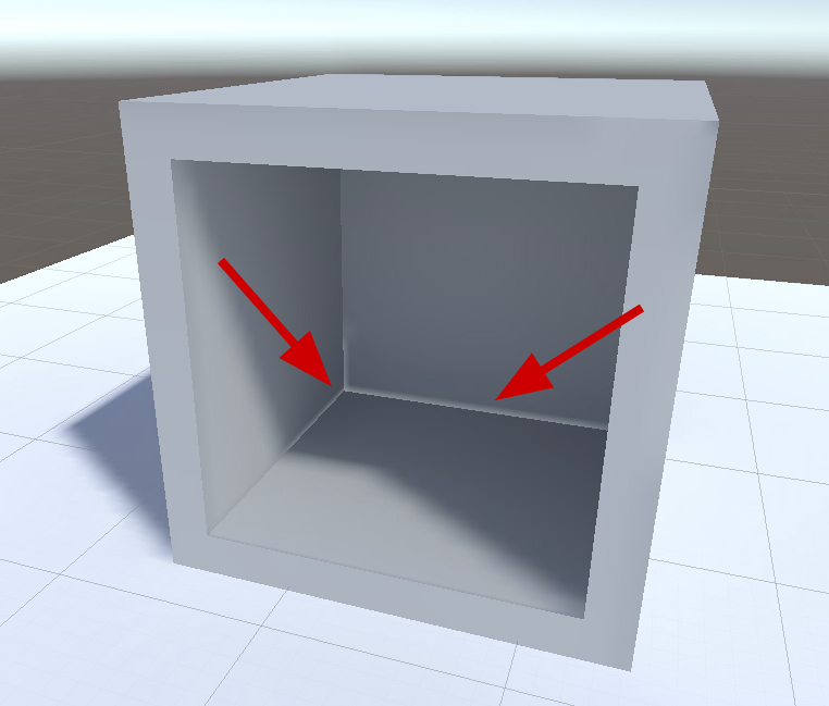
See in Glossary faces, and uses the charts’ lighting data to calculate the final appearance. Because of the way GPU sampling works, data from one chart can bleed onto another if they are too close to each other. This usually leads to unintended artifacts such as aliasing, pixelation, and so on.

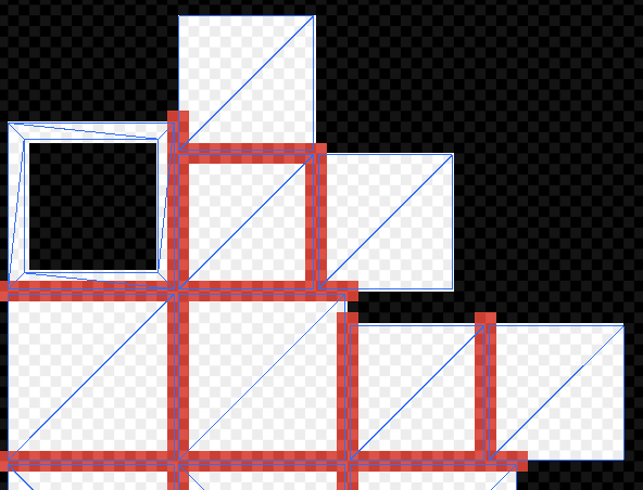
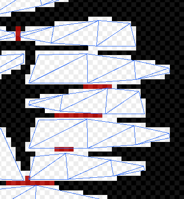
To avoid light bleeding, there must be a sufficient amount of space between charts. When a GPU samples a lightmap, the lighting system calculates the final sample value from the four texels closest to the sampled point (assuming bilinear filtering is used). These four texels are called the bilinear “neighborhood” of the sampled point. Charts are too close together if they overlap — that is, if the neighbourhood of any point inside a chart overlaps with the neighborhood of any point in another chart. In the image below, the white pixelsThe smallest unit in a computer image. Pixel size depends on your screen resolution. Pixel lighting is calculated at every screen pixel. More info
See in Glossary indicate chart neighbourhoods, and red pixels indicate overlapping neighbourhoods.

Determining optimal chart placements and spacing can be difficult, because it depends on several parameters (such as lightmap resolution, mesh UVs, and Importer settings). For this reason, Unity provides the ability to identify these issues easily, as outlined in the following section.
Identification
There are three ways to identify overlaps:
-
Keep an eye on Unity’s console. If Unity detects overlapping UVs, it prints a warning message with a list of affected GameObjectsThe fundamental object in Unity scenes, which can represent characters, props, scenery, cameras, waypoints, and more. A GameObject’s functionality is defined by the Components attached to it. More info
See in Glossary. -
Use the UV Overlap draw mode in the SceneA Scene contains the environments and menus of your game. Think of each unique Scene file as a unique level. In each Scene, you place your environments, obstacles, and decorations, essentially designing and building your game in pieces. More info
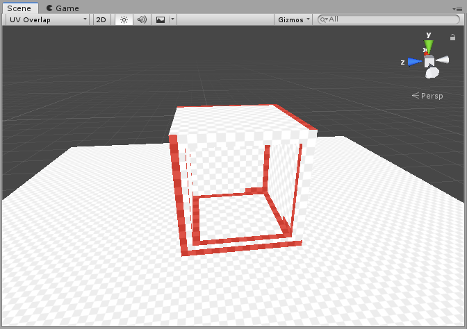
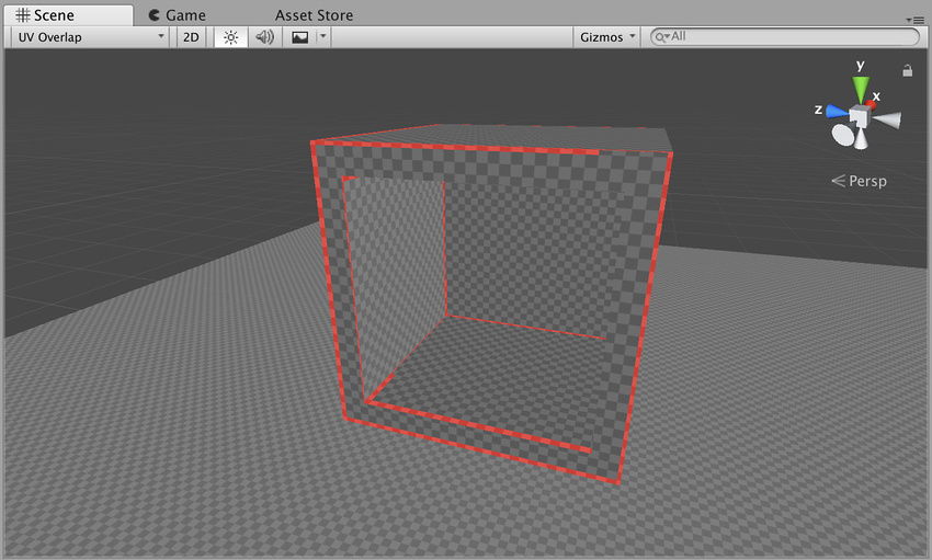
See in Glossary View (see GI visualizations in the Scene View for more information). When you have this mode enabled, Unity adds a red highlight to chart texels that are too close to texels of other charts. This is especially useful if you discover an artefact in the Scene viewAn interactive view into the world you are creating. You use the Scene View to select and position scenery, characters, cameras, lights, and all other types of Game Object. More info
See in Glossary, and want to quickly examine whether UV overlap is causing it.

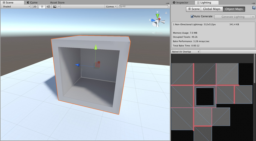
- Use Baked Lightmaps Preview. Select a GameObject and go to the Lighting window and then choose the Baked Lightmaps tab. Double-click the highlighted lightmap, navigate to the Preview window, and select Baked UV Overlap (see dropdown in upper right corner). The Preview window colours problematic texels red in this view.

Solutions
There is no one single solution for UV overlap, because there are so many things that can cause it. Here are the most common solutions to consider:
- If you provide lightmap UVs yourself, add margins using your modelling package.
- If Unity automatically generates the lightmap UVs for a Model, you can tell Unity to increase the pack margin. The simplest way to do this is to set the Margin Method to Calculate, and set an appropriate Min Lightmap Resolution and Min Object Scale. If you prefer to set Margin Method to Manual, you can adjust the Pack Margin value directly. For more information on these settings, see documentation on Generating lightmapping UVs.
- Increase the resolution of the entire lightmap. This will increase the numbers of pixels between the charts, and therefore reduce the likelihood of bleeding. The downside is that your lightmap may become too large. You can do this in the Lighting tab under Lightmapper Settings.
- Increase the resolution of a single GameObject. This allows you to increase lightmap resolution only for GameObjects that have overlapping UVs. Though less likely, this can also increase your lightmap size. You can change a GameObject’s lightmap resolution inside its Mesh RendererA mesh component that takes the geometry from the Mesh Filter and renders it at the position defined by the object’s Transform component. More info
See in Glossary under Lightmap Settings.

Каждая карта освещенияпредварительно обработанная текстура, содержащая эффекты источников света на статических объектах сцены. Карты освещения накладываются поверх геометрии сцены для создания эффекта освещения. Подробнее
См. в Словарь содержит ряд диаграмм . Во время выполнения Unity сопоставляет эти диаграммы с сеткойосновным графическим примитивом Unity. Меши составляют большую часть ваших 3D-миров. Unity поддерживает триангулированные или четырехугольные полигональные сетки. Поверхности Nurbs, Nurms, Subdiv должны быть преобразованы в полигоны. Подробнее
Посмотреть в Словарь лица и использовать данные освещения диаграмм для расчета окончательного внешность. Из-за того, как работает выборка графического процессора, данные с одной диаграммы могут накладываться на другую, если они расположены слишком близко друг к другу. Обычно это приводит к непреднамеренным артефактам, таким как псевдонимы, пикселизация и т. д.

Во избежание легкого размытия между диаграммами должно быть достаточно места. Когда GPU производит выборку карты освещения, система освещения вычисляет окончательное значение выборки из четырех текселей, ближайших к точке выборки (при условии, что используется билинейная фильтрация). Эти четыре тексела называются билинейной «окрестностью» точки выборки. Диаграммы располагаются слишком близко друг к другу, если они перекрываются, то есть если окрестности любой точки внутри диаграммы перекрываются с окрестностями любой точки на другой диаграмме. На изображении ниже белые пикселинаименьшие единицы компьютерного изображения. Размер пикселя зависит от разрешения вашего экрана. Пиксельное освещение рассчитывается для каждого пикселя экрана. Подробнее
См. в Словарь – это окрестности диаграммы, а красные пиксели — перекрывающиеся окрестности.
Определить оптимальное расположение и расстояние между диаграммами может быть сложно, так как это зависит от нескольких параметров (таких как разрешение карты освещения, UV сетки и настройки Importer). По этой причине Unity позволяет легко выявлять такие проблемы, как описано в следующем разделе.
Идентификация
Есть три способа определить перекрытия:
-
Следите за консолью Unity. Если Unity обнаруживает перекрывающиеся UV-развертки, она печатает предупреждающее сообщение со списком затронутых GameObjectsОсновной объект в сценах Unity, который может представлять персонажи, реквизит, декорации, камеры, путевые точки и многое другое. Функциональность GameObject определяется прикрепленными к нему компонентами. Подробнее
См. в Словарь. -
Используйте режим рисования UV Overlap в СценеСцена содержит среды и меню вашей игры. Думайте о каждом уникальном файле сцены как об уникальном уровне. В каждой сцене вы размещаете свое окружение, препятствия и декорации, по сути проектируя и создавая свою игру по частям. Подробнее
См. в виде Словарь (см. GI-визуализации в представлении «Сцена» для получения дополнительной информации). Когда этот режим включен, Unity добавляет красную подсветку к текселям диаграммы, которые находятся слишком близко к текселям других диаграмм. Это особенно полезно, если вы обнаружили артефакт в виде сценыинтерактивном представлении мира, который вы создаете. Вы используете Scene View для выбора и размещения пейзажей, персонажей, камер, источников света и всех других типов игровых объектов. Подробнее
Посмотрите в Словарь и хотите быстро проверить, не вызывает ли это перекрытие УФ-излучения.

- Используйте Предварительный просмотр запеченных карт освещения. Выберите GameObject и перейдите в окно Освещение, а затем выберите вкладку Baked Lightmaps. Дважды щелкните выделенную карту освещения, перейдите в окно предварительного просмотра и выберите Baked UV Overlap (см. раскрывающийся список в правом верхнем углу). В этом представлении окно предварительного просмотра окрашивает проблемные тексели в красный цвет.

Решения
Не существует единого решения проблемы перекрытия УФ-излучения, так как существует множество факторов, которые могут его вызвать. Вот наиболее распространенные решения:
- Если вы предоставляете UV-карты освещения самостоятельно, добавьте поля с помощью пакета моделирования.
- Если Unity автоматически генерирует UV-карты освещения для модели, вы можете указать Unity увеличить запас упаковки. Самый простой способ сделать это — установить для параметра Метод поля значение Рассчитать и установить соответствующие Минимальное разрешение карты освещения и Минимальный масштаб объекта. . Если вы предпочитаете установить для параметра Метод маржи значение Вручную, вы можете напрямую настроить значение Упаковать маржу. Дополнительную информацию об этих настройках см. в документации по Создание карт освещения UV.
- Увеличить разрешение всей карты освещения. Это увеличит количество пикселей между диаграммами и, следовательно, уменьшит вероятность протечки. Недостатком является то, что ваша карта освещения может стать слишком большой. Это можно сделать на вкладке Освещение в разделе Настройки Lightmapper.
- Увеличить разрешение одного игрового объекта. Это позволяет увеличить разрешение карты освещения только для игровых объектов с перекрывающимися UV-развертками. Хотя это менее вероятно, это также может увеличить размер карты освещения. Вы можете изменить разрешение карты освещения GameObject внутри его Mesh Rendererкомпонента сетки, который берет геометрию из Mesh Filter и визуализирует ее в положение, определяемое компонентом Transform объекта. Подробнее
См. в Словарь в разделе Настройки карты освещения.
Each lightmapA pre-rendered texture that contains the effects of light sources on static objects in the scene. Lightmaps are overlaid on top of scene geometry to create the effect of lighting. More info
See in Glossary contains a number of charts. At run time, Unity maps these charts onto meshThe main graphics primitive of Unity. Meshes make up a large part of your 3D worlds. Unity supports triangulated or Quadrangulated polygon meshes. Nurbs, Nurms, Subdiv surfaces must be converted to polygons. More info
See in Glossary faces, and uses the charts’ lighting data to calculate the final appearance. Because of the way GPU sampling works, data from one chart can bleed onto another if they are too close to each other. This usually leads to unintended aliasing, pixelation, and other graphical results (these are called artifacts).
To avoid light bleeding, there must be a sufficient amount of space between charts. When a GPU samples a lightmap, the lighting system calculates the final sample value from the four texels closest to the sampled point (assuming bilinear filtering is used). These four texels are called the bilinear “neighborhood” of the sampled point. Charts are too close together if they overlap — that is, if the neighbourhood of any point inside a chart overlaps with the neighborhood of any point in another chart. In the image below, the white pixelsThe smallest unit in a computer image. Pixel size depends on your screen resolution. Pixel lighting is calculated at every screen pixel. More info
See in Glossary indicate chart neighbourhoods, and red pixels indicate overlapping neighbourhoods.

Determining optimal chart placements and spacing can be difficult, because it depends on several parameters (such as lightmap resolution, mesh UVs, and Importer settings). For this reason, Unity provides the ability to identify these issues easily, as outlined in the following section.
Identification
There are three ways to identify overlaps:
-
Keep an eye on Unity’s console. If Unity detects overlapping UVs, it prints a warning message with a list of affected GameObjectsThe fundamental object in Unity scenes, which can represent characters, props, scenery, cameras, waypoints, and more. A GameObject’s functionality is defined by the Components attached to it. More info
See in Glossary. -
Use the UV Overlap draw mode in the SceneA Scene contains the environments and menus of your game. Think of each unique Scene file as a unique level. In each Scene, you place your environments, obstacles, and decorations, essentially designing and building your game in pieces. More info
See in Glossary View (see GI visualizations in the Scene View for more information). When you have this mode enabled, Unity adds a red highlight to chart texels that are too close to texels of other charts. This is especially useful if you discover an artefact in the Scene viewAn interactive view into the world you are creating. You use the Scene View to select and position scenery, characters, cameras, lights, and all other types of Game Object. More info
See in Glossary, and want to quickly examine whether UV overlap is causing it.
- Use Baked Lightmaps Preview. Select a GameObject and go to the Lighting window and then choose the Baked Lightmaps tab. Double-click the highlighted lightmap, navigate to the Preview window, and select Baked UV Overlap (see dropdown in upper right corner). The Preview window colours problematic texels red in this view.

Solutions
There is no one single solution for UV overlap, because there are so many things that can cause it. Here are the most common solutions to consider:
-
If Unity is automatically creating the lightmap UVs, you can increase the Pack Margin. To do this, navigate to the Model tab of the Mesh’s import settings. Make sure Generate Lightmap UVs is enabled, then fold out Advanced and use the Pack Margin slider to increase the value. This creates more spacing between charts, which reduces likelihood of overlap. However, this also increase the total space requirement for the lightmap, so try to apply enough spacing to avoid artifacts, but no more. For more information on lightmap UVs that Unity creates automatically, see documentation on Generating lightmapping UVs.
-
If you provide lightmap UVs yourself, you can try adding margins using your modelling package.
-
Increase the resolution of the entire lightmap. This will increase the numbers of pixels between the charts, and therefore reduce the likelihood of bleeding. The downside is that your lightmap may become too large. You can do this in the Lighting tab under Lightmapper Settings.
-
Increase the resolution of a single GameObject. This allows you to increase lightmap resolution only for GameObjects that have overlapping UVs. Though less likely, this can also increase your lightmap size. You can change a GameObject’s lightmap resolution inside its Mesh RendererA mesh component that takes the geometry from the Mesh Filter and renders it at the position defined by the object’s Transform component. More info
See in Glossary under Lightmap Settings.

Progressive Lightmapper added in 2018.1 NewIn20181
2018–03–28 Page published
Copyright © 2020 Unity Technologies
优美缔软件(上海)有限公司 版权所有
«Unity»、Unity 徽标及其他 Unity 商标是 Unity Technologies 或其附属机构在美国及其他地区的商标或注册商标。其他名称或品牌是其各自所有者的商标。
Each lightmapA pre-rendered texture that contains the effects of light sources on static objects in the scene. Lightmaps are overlaid on top of scene geometry to create the effect of lighting. More info
See in Glossary contains a number of charts. At run time, Unity maps these charts onto meshThe main graphics primitive of Unity. Meshes make up a large part of your 3D worlds. Unity supports triangulated or Quadrangulated polygon meshes. Nurbs, Nurms, Subdiv surfaces must be converted to polygons. More info
See in Glossary faces, and uses the charts’ lighting data to calculate the final appearance. Because of the way GPU sampling works, data from one chart can bleed onto another if they are too close to each other. This usually leads to unintended aliasing, pixelation, and other graphical results (these are called artifacts).
To avoid light bleeding, there must be a sufficient amount of space between charts. When a GPU samples a lightmap, the lighting system calculates the final sample value from the four texels closest to the sampled point (assuming bilinear filtering is used). These four texels are called the bilinear “neighborhood” of the sampled point. Charts are too close together if they overlap — that is, if the neighbourhood of any point inside a chart overlaps with the neighborhood of any point in another chart. In the image below, the white pixelsThe smallest unit in a computer image. Pixel size depends on your screen resolution. Pixel lighting is calculated at every screen pixel. More info
See in Glossary indicate chart neighbourhoods, and red pixels indicate overlapping neighbourhoods.
Determining optimal chart placements and spacing can be difficult, because it depends on several parameters (such as lightmap resolution, mesh UVs, and Importer settings). For this reason, Unity provides the ability to identify these issues easily, as outlined in the following section.
Identification
There are three ways to identity overlaps:
-
Keep an eye on Unity’s console. If Unity detects overlapping UVs, it prints a warning message with a list of affected GameObjectsThe fundamental object in Unity scenes, which can represent characters, props, scenery, cameras, waypoints, and more. A GameObject’s functionality is defined by the Components attached to it. More info
See in Glossary. -
Use the UV Overlap draw mode in the Scene ViewAn interactive view into the world you are creating. You use the Scene View to select and position scenery, characters, cameras, lights, and all other types of Game Object. More info
See in Glossary (see GI visualizations in the Scene View for more information). When you have this mode enabled, Unity adds a red highlight to chart texels that are too close to texels of other charts. This is especially useful if you discover an artefact in the SceneA Scene contains the environments and menus of your game. Think of each unique Scene file as a unique level. In each Scene, you place your environments, obstacles, and decorations, essentially designing and building your game in pieces. More info
See in Glossary view, and want to quickly examine whether UV overlap is causing it.
- Use Object Maps in the Lighting tab. Select an object and go to the Lighting tab and then choose Object Maps. Make sure to select Baked UV Overlap in the dropdown. Problematic texels are colored red in this view.
Solutions
There is no one single solution for UV overlap, because there are so many things that can cause it. Here are the most common solutions to consider:
-
If Unity is automatically creating the lightmap UVs, you can increase the Pack Margin. To do this, navigate to the Model tab of the Mesh’s import settings. Make sure Generate Lightmap UVs is enabled, then fold out Advanced and use the Pack Margin slider to increase the value. This creates more spacing between charts, which reduces likelihood of overlap. However, this also increase the total space requirement for the lightmap, so try to apply enough spacing to avoid artifacts, but no more. For more information on lightmap UVs that Unity creates automatically, see documentation on Generating lightmapping UVs.
-
If you provide lightmap UVs yourself, you can try adding margins using your modelling package.
-
Increase the resolution of the entire lightmap. This will increase the numbers of pixels between the charts, and therefore reduce the likelihood of bleeding. The downside is that your lightmap may become too large. You can do this in the Lighting tab under Lightmapper Settings.
-
Increase the resolution of a single GameObject. This allows you to increase lightmap resolution only for GameObjects that have overlapping UVs. Though less likely, this can also increase your lightmap size. You can change a GameObject’s lightmap resolution inside its Mesh RendererA mesh component that takes the geometry from the Mesh Filter and renders it at the position defined by the object’s Transform component. More info
See in Glossary under Lightmap Settings.
Progressive Lightmapper added in 2018.1 NewIn20181
2018–03–28 Page published with limited editorial review
Did you find this page useful? Please give it a rating: