blink_bluepill_rust
Trying to blink an LED on a 1.35€ «blue pill» STM32F103C8 board.
I guess things won’t work on first try so I take notes in this file.
Chapter 1 and 2 of The Embedded Rust Book. (Install to «Hello, world!»)
Installing
I already hade Rustup installed. I removed the unsued toolchains and then followed instructions in chapter 1.3 and 1.3.3 (I used Windows, don’t judge) of The Embedded Rust Book.
I also wanted to add cargo-generate as told in chapter 1.2 (cargo install cargo-generate), but at some point I required to install msvc which is a really 1.1Gb download just a C compiler on windows. Since it is an optionnal step I skept it.
I upgraded y aliexpress clone ST-LINK V2 firmware to latest version using ST-LinkUpgrade.exe found in «ST Link utility» by ST.
UNEXPECTED idcode: 0x2ba01477
After following chapters 1.3 and 1.3.3, I tryed starting OpenOCD to check that if found my STLink-V2-1 programmer and my Blue Pill board. The Book says to type : openocd -f interface/stlink-v2-1.cfg -f target/stm32f3x.cfgbut since my board has an stm32f103, I used openocd -f interface/stlink-v2-1.cfg -f target/stm32f1x.cfg:
D:codeOpenOCDbin>openocd -f interface/stlink-v2-1.cfg -f target/stm32f1x.cfg
GNU MCU Eclipse 64-bit Open On-Chip Debugger 0.10.0+dev-00352-gaa6c7e9b (2018-10-20-06:24)
Licensed under GNU GPL v2
For bug reports, read
        http://openocd.org/doc/doxygen/bugs.html
WARNING: interface/stlink-v2-1.cfg is deprecated, please switch to interface/stlink.cfg
Info : auto-selecting first available session transport "hla_swd". To override use 'transport select <transport>'.
Info : The selected transport took over low-level target control. The results might differ compared to plain JTAG/SWD
adapter speed: 1000 kHz
adapter_nsrst_delay: 100
none separate
Info : Listening on port 6666 for tcl connections
Info : Listening on port 4444 for telnet connections
Info : Unable to match requested speed 1000 kHz, using 950 kHz
Info : Unable to match requested speed 1000 kHz, using 950 kHz
Info : clock speed 950 kHz
Info : STLINK v2 JTAG v32 API v2 SWIM v7 VID 0x0483 PID 0x3748
Info : using stlink api v2
Info : Target voltage: 3.204230
Warn : UNEXPECTED idcode: 0x2ba01477
Error: expected 1 of 1: 0x1ba01477
in procedure 'init'
in procedure 'ocd_bouncer'
That does not work, the interesting lines are:
Warn : UNEXPECTED idcode: 0x2ba01477
Error: expected 1 of 1: 0x1ba01477
The idcode returned by the CPU does is not the expected one. That is not completely surprising: I bought the chipest board from aliexpress, and thought advertised havinf an stm32f103 chip from ST Micro, it comes with an advertised-as-perfect-replacement cs32f103c8t6 by CKS. It supposed to be a perfect clone (they do not even provide a datasheet for it), but this part returns a slightly different idcode.
The idcode is if cheap identifier. It is part of the JTAG protocol. (We do not use JTAG here but the STLink protocol, which IIUC adds the possibility to use a simpler/cheaper connection between some ST Micro chips and the computer). At address (0x0) the protocol allow the chip to expose an identifier called DPIDR (for ‘Debug Port Identification register’, see chapter 2.2.5 of ARM Debugger Interface Architecture Specification. The documentation says that bits 28 to 31 contains Revision code. The meaning of this field is IMPLEMENTATIONDEFINED..
Since only bits 28 and 29 are different, we can expect that the chip is still compatible, and create a new configuration file for OpenOCD tu just tell him to expect the actually received idcode.
I copied the openocdscriptstargetstm32f1x.cfg file, naming the copy cs32f1x.cfg and changed:
- the name of the chip:
if { [info exists CHIPNAME] } {
   set _CHIPNAME $CHIPNAME
} else {
   set _CHIPNAME cs32f1x
}
- the idcode:
#jtag scan chain
if { [info exists CPUTAPID] } {
   set _CPUTAPID $CPUTAPID
} else {
   if { [using_jtag] } {
      # See STM Document RM0008 Section 26.6.3
      set _CPUTAPID 0x3ba00477
   } {
      # this is the SW-DP tap id not the jtag tap id
      set _CPUTAPID 0x2ba01477
   }
}
and could try running openocd again:
D:codeOpenOCDbin>openocd -f interface/stlink-v2-1.cfg -f target/cs32f1x.cfg
GNU MCU Eclipse 64-bit Open On-Chip Debugger 0.10.0+dev-00352-gaa6c7e9b (2018-10-20-06:24)
Licensed under GNU GPL v2
For bug reports, read
        http://openocd.org/doc/doxygen/bugs.html
WARNING: interface/stlink-v2-1.cfg is deprecated, please switch to interface/stlink.cfg
Info : auto-selecting first available session transport "hla_swd". To override use 'transport select <transport>'.
Info : The selected transport took over low-level target control. The results might differ compared to plain JTAG/SWD
adapter speed: 1000 kHz
adapter_nsrst_delay: 100
none separate
Info : Listening on port 6666 for tcl connections
Info : Listening on port 4444 for telnet connections
Info : Unable to match requested speed 1000 kHz, using 950 kHz
Info : Unable to match requested speed 1000 kHz, using 950 kHz
Info : clock speed 950 kHz
Info : STLINK v2 JTAG v32 API v2 SWIM v7 VID 0x0483 PID 0x3748
Info : using stlink api v2
Info : Target voltage: 3.205816
Info : cs32f1x.cpu: hardware has 6 breakpoints, 4 watchpoints
Info : Listening on port 3333 for gdb connections
_
It seems better.
(Thanks to tsman on eevblog forum)
New project from template
I skept the installation of cargo-generate (because of msvc), so I could not use it to generate the Rust project from the template. I also did not want to create them by cloning the git repository (because I already hade an existing git repo with this readme.md file, so I just download [https://github.com/rust-embedded/cortex-m-quickstart/archive/master.zip] and unziped it in a blue_pill_blinkysubdirectory.and changed the project name toblue_pill_blinky in the blue_pill_blinkyCargo.toml file (twice)
memory.x
Since the template is meant for stm32f4 with a differente quantity of flash than mine, I edited to memory.x file (which, I believe, is used to generate the linker scripts) with values I found in the stm32f103 datasheet. Hoping that the «C8» at the end of the marking of my CKS mcu means the same thing as the «C8» at the end of a genuin stm32f103, I guess this chip has 64kb ok flash (see chapter 7 of the datasheet) and it should have 20Kb of ram (first page of the datasheet). The memory map (chapter 4 of the same datasheet) tells me that flash memory starts at 0x0800.0000 and static ram starts at 0x2000-0000, giving the following content for the memory.x file:
/* Linker script for the STM32F103C8T6 */
MEMORY
{
  FLASH : ORIGIN = 0x08000000, LENGTH = 64K
  RAM : ORIGIN = 0x20000000, LENGTH = 20K
}
(I removed the comments from the template)
Compiling for the proper
We want to compile for our microcontoller. A microcontoler is an microprocessor packages with things like RAM, Flash memory, digital to analog converters, timers… Rust needs to know for which mcu we want to compile. The stm32f103 has a Cortex-M3 core (which is a proprietary but standard core found on many mcu form different manufacturers). Its architecture is called «ARMv7-M», this information is in the datasheet but I got it from wikipedia. So in .cargo/config, for the Blue Pill it will be:
[build]
target = "thumbv7m-none-eabi"    # Cortex-M3
thumb here relate to the instruction-set we want to use. Since Cortex-M only support the newer Thumb instructon (which is a 16 bits instructions set, as opposed to the older 32 bits ARM set, it’s faster and take less space, see wikipedia again).
Deleting the target directory
I renamed the project, hence the project’s directory name. This caused Cargo to be unable to compile (not finding the linker file). The solution was to delete the target directory and build again.
Changing the dependency and main.rs
The compilation never ended, so I replaced the content of my main.rs file with the content of the hello-world found in template/ directory (it came with the template).
I’m not sur this step is needed bu I did it.
Switching the linker
The compilation never ended, stucked at step 32/33. Fortunately some comment in the .cargo/config file cought my attention:
  # LLD (shipped with the Rust toolchain) is used as the default linker
   "-C", "link-arg=-Tlink.x",

  # if you run into problems with LLD switch to the GNU linker by commenting out this line
  # "-C", "linker=arm-none-eabi-ld",
I commented the line for the LLD linker and uncommented the one for the GNU linker and could complete the build.
openocd.cfg
I edited the openocd.cfg file that came with the template to use the openocd configuration I made for my weird stm32 clone:
source [find target/cs32f1x.cfg]
Once this is done, I can run openocd from the same directory the openocd.cfg file is in and no longer need to pass the configuration for the CKS clone (nor for the ST-Link V2-1 which was the default configuration in the openocd.cfg file, I didn’t need to change that but mays you do):
D:coderustblink_bluepill_rustblue_pill_blinky>d:codeOpenOCDbinopenocd.exe
GNU MCU Eclipse 64-bit Open On-Chip Debugger 0.10.0+dev-00352-gaa6c7e9b (2018-10-20-06:24)
Licensed under GNU GPL v2
For bug reports, read
        http://openocd.org/doc/doxygen/bugs.html
WARNING: interface/stlink-v2-1.cfg is deprecated, please switch to interface/stlink.cfg
Info : auto-selecting first available session transport "hla_swd". To override use 'transport select <transport>'.
Info : The selected transport took over low-level target control. The results might differ compared to plain JTAG/SWD
adapter speed: 1000 kHz
adapter_nsrst_delay: 100
none separate
Info : Listening on port 6666 for tcl connections
Info : Listening on port 4444 for telnet connections
Info : Unable to match requested speed 1000 kHz, using 950 kHz
Info : Unable to match requested speed 1000 kHz, using 950 kHz
Info : clock speed 950 kHz
Info : STLINK v2 JTAG v32 API v2 SWIM v7 VID 0x0483 PID 0x3748
Info : using stlink api v2
Info : Target voltage: 3.204230
Info : cs32f1x.cpu: hardware has 6 breakpoints, 4 watchpoints
Info : Listening on port 3333 for gdb connections
Starting gdb
Start gdb by replace <gbd> in the command given in chapter 2.2. with the name of the executable of the gdb you downloaded from ST website. Also since I juste ran cargo build, cargo did not copy the source files in examples/ then I used a different directory from the one given the Embedded Rust Book:
arm-none-eabi-gdb -d targetthumbv7m-none-eabidebug
but that did no seem to work. Anyway I could use the file command to tell where my firmware is, gdb to openocd running in another shell, and upload the firmware:
(gdb) file target/thumbv7m-none-eabi/debug/b
blue_pill_blinky    blue_pill_blinky.d  build/
(gdb) file target/thumbv7m-none-eabi/debug/blue_pill_blinky
A program is being debugged already.
Are you sure you want to change the file? (y or n) y
Reading symbols from target/thumbv7m-none-eabi/debug/blue_pill_blinky...
(No debugging symbols found in target/thumbv7m-none-eabi/debug/blue_pill_blinky)
(gdb) load
Start address 0x8000, load size 0
Transfer rate: 0 bits in <1 sec.
(gdb)
I guess I uploaded something because the Blue Pill stopped blinking the LED that was controller by the original firmware.
Trying to execute
I tryed following the chapter 2.2 form there, but «next» was not of much help when gdb could not find the debugging symbol in my binary. So I tryed running the code (continue send to openocd from gdb) but nothing appeared in the openocd console. I was expecting an «Hello, world!».
I quit openocd and gdb, and use STM32 ST-LINK Utility.exe from ST. I clicked «connect the target» and look if the flash of the Blue Pill seemed to contain the «Hello, world!» string: it did not. I reset the Blue Pill and it start blinking. It seems I did not flash the firmware.
Semihosting works!
After chatting on IRC, I tryed to use the GCC toolchain instead of just the GNU linker (see comments in .cargo/config) and it compiled and I could upload and exectue the firmware.
This is the value that works for me for rustflags in .cargo/configfile:
rustflags = [
  "-C", "linker=arm-none-eabi-gcc",
  "-C", "link-arg=-Wl,-Tlink.x",
  "-C", "link-arg=-nostartfiles",
]
I now can build:
D:coderustblink_bluepill_rustblue_pill_blinky>cargo build
[...]
   Compiling cortex-m-rt-macros v0.1.5
    Finished dev [unoptimized + debuginfo] target(s) in 40.82s
Now I can continue try flashing the firmware again and debugging it. I understood that I was not using the openocd.dbg file provided by the template, so here is what I do now:
- Start OpenOCD
D:coderustblink_bluepill_rustblue_pill_blinky>d:codeOpenOCDbinopenocd.exe
GNU MCU Eclipse 64-bit Open On-Chip Debugger 0.10.0+dev-00352-gaa6c7e9b (2018-10-20-06:24)
Licensed under GNU GPL v2
For bug reports, read
       http://openocd.org/doc/doxygen/bugs.html
WARNING: interface/stlink-v2-1.cfg is deprecated, please switch to interface/stlink.cfg
Info : auto-selecting first available session transport "hla_swd". To override use 'transport select <transport>'.
Info : The selected transport took over low-level target control. The results might differ compared to plain JTAG/SWD
adapter speed: 1000 kHz
adapter_nsrst_delay: 100
none separate
Info : Listening on port 6666 for tcl connections
Info : Listening on port 4444 for telnet connections
Info : Unable to match requested speed 1000 kHz, using 950 kHz
Info : Unable to match requested speed 1000 kHz, using 950 kHz
Info : clock speed 950 kHz
Info : STLINK v2 JTAG v32 API v2 SWIM v7 VID 0x0483 PID 0x3748
Info : using stlink api v2
Info : Target voltage: 3.203691
Info : cs32f1x.cpu: hardware has 6 breakpoints, 4 watchpoints
Info : Listening on port 3333 for gdb connections
(I start from the directory where openocd.cfg file is, so I don’t need to provide the -f interface/stlink-v2-1.cfg -f target/cs32f1x.cfg. And remember you might or might not need to make and use the cs32f1x.cfg file instead of target/stm32f1x.cfg)
- Start gdb
D:coderustblink_bluepill_rustblue_pill_blinky>arm-none-eabi-gdb -x openocd.gdb targetthumbv7m-none-eabidebugblue_pill_blinky
d:Program Files (x86)GNU Tools ARM Embedded8 2018-q4-majorbinarm-none-eabi-gdb.exe: warning: Couldn't determine a path for the index cache directory.
GNU gdb (GNU Tools for Arm Embedded Processors 8-2018-q4-major) 8.2.50.20181213-git
Copyright (C) 2018 Free Software Foundation, Inc.
[...]
Type "apropos word" to search for commands related to "word"...
Reading symbols from targetthumbv7m-none-eabidebugblue_pill_blinky...
core::sync::atomic::compiler_fence (order=32) at libcore/sync/atomic.rs:2351
2351    libcore/sync/atomic.rs: No such file or directory.
Breakpoint 1 at 0x8000f68: file C:UsersFabien.cargoregistrysrcgithub.com-1ecc6299db9ec823cortex-m-rt-0.6.7srclib.rs, line 550.
Function "UserHardFault" not defined.
Make breakpoint pending on future shared library load? (y or [n]) [answered N; input not from terminal]
Breakpoint 2 at 0x80015aa: file C:UsersFabien.cargoregistrysrcgithub.com-1ecc6299db9ec823panic-halt-0.2.0srclib.rs, line 32.
Breakpoint 3 at 0x8000402: file srcmain.rs, line 13.
semihosting is enabled
Loading section .vector_table, size 0x400 lma 0x8000000
Loading section .text, size 0x1220 lma 0x8000400
Loading section .rodata, size 0x2ac lma 0x8001620
Start address 0x8000f26, load size 6348
Transfer rate: 17 KB/sec, 2116 bytes/write.
Note: automatically using hardware breakpoints for read-only addresses.
halted: PC: 0x08000f7c
DefaultPreInit ()
   at C:UsersFabien.cargoregistrysrcgithub.com-1ecc6299db9ec823cortex-m-rt-0.6.7srclib.rs:559
559     pub unsafe extern "C" fn DefaultPreInit() {}
(gdb) _
I now add the -x openocd.gdb parameter which is a script that does some things for us (like connecting gdb to openocd). Since the script is ran before we can use the file command to tell gdb where the elf file for the firmware is, we add the path to this as the last argument to gdb.
When the script is ran, you will see some information displayed in the other shell (the one with openocd running). The semihosting is enabled tells you that semihosting is activated. As the Rust Embedded Book explains, this allows us to basically use the debugger as stdout, hence display messages in OpenOCD.
- step through
after using thenextcommand in dgb, I finally got the expected message in OpenOCD:
[...]
Info : halted: PC: 0x08000626
Hello, world!
Info : halted: PC: 0x08000412
[...]
Chapter 3 of The Embedded Rust Book (First led blinking)
Up to now, I have not done much thing wich is specific to the stm32f103c8 (clone) I use:
- I installed ARM toolchain for Cortex-M (and Cortex-R) but this covers all the mcus in Cortex-M family (ARM design the core, and license the design to different manufacturers who produce them with differents options and package them with different peripherals)
- I configured the
thumbv7mtarget in.cargo/config(which covers all the Cortex-M3) - I changed the
idcodein OpenOCD so I can tell it whichidcodeto expect from my clone - I set the proper size and base address for the flash and sram in the
memory.xfile.
Now let’s try to follow the Chapter 3 of The Rust Embedded Book, adapting the peripheral to the one available on the stm32f103. At first I want to follow a rather close to the metal approach (writting to Special Fucntion Registers, which are registers each having a fixed address in the address space of the MCU which serve to control the peripherals on the MCU).
Timer
At first I wander why the datasheet of the stm32f103 didn’t give information about the special function registers used to control the timers. The thing is that the timer are not designed by ST (manufacturer of the stm32’s), but standard Cortex peripherals designed by ARM. The information are in ARM’s Cortex-M3 documentation and the System Timer has the same SFR (Special Function Registers) at the same address as the System Timer on the Cortex-M4 used by the authors of the book (which is an STM32F3DISCOVERY with a Cortex-M4F STM32F303VCT6 microcontroller)
I wanted to go step by step, and execute even the first steps of the 3.1(«A First Attempt») chapter. It could have been easy to rewrite (or even copy/paste) but I learn more by rewritting the code from The ERB («Embedded Rust Book» is a nice name but it’s annoying when you type it so often  ), unfortunately this line did not compile:
let time = unsafe { std::ptr::read_volatile(&mut systick.cvr) };
The reason is that we compile for a microcontroller, hence want to get ride of the many things that comes in Rust standard lib. I edited my frist code which started with the #![no_std] attribute which tells the Rust compiler not to use this library. Of course you can not use std::ptr::read_volatile then because it is in the standard library (that’s what the std stands for : standard).
I went to the Rust Embedded IRC channel to discuss this issue, it appeared the standard library does not exist for Cortex-M. The standard library wraps and adds functionnalities on the Core library and these additions are not wanted (because of limited ressource) or even possible («jamesmunns: The Standard Library has all sorts of dependencies on things like filesystems, networking concepts, heap allocations, etc.»). Fortunately, std::ptr::read_volatile is just a proxy for core::ptr::read_volatile, so we can use the Core Library instead. (This hade already been reported to the ERB team, but was dormant. Someone on the IRC channel made a pull request five minutes after I told them about my problem so you may not see it when you read the ERB.)
So, now we have something that should work:
#![no_main]
#![no_std]

extern crate panic_halt;

use cortex_m_rt::entry;
use cortex_m_semihosting::hprintln;

#[repr(C)]
struct SysTick {
    pub csr: u32,
    pub rvr: u32,
    pub cvr: u32,
    pub calib: u32,
}

#[entry]
fn main() -> ! {

    let systick = unsafe { &mut *(0xE000_E010 as *mut SysTick) };

    loop {
        let current_value_register = unsafe { core::ptr::read_volatile(&mut systick.cvr) };
        hprintln!("System timer current value is now {}.", current_value_register).unwrap();
    }
}
and after starting gdb and running (you need to continue twice, c is a shortcut for continuecommand) you get this fantastic output:
System timer current value is now 0.
System timer current value is now 0.
System timer current value is now 0.
System timer current value is now 0.
System timer current value is now 0.
System timer current value is now 0.
Not realy what we expected…
The code in Chapter 3.1 of the ERB aims at showing you how to create code, not how to use the timer on an stm32f. They hide some important things that can be found in the ARM’s Cortex-M3 documentation:
- You need to set the Reload Value Register, which contain the value at which the timer will be reset when it reaches 0
- You need to enable the counter (and eventually set the source clock you want to use, I will use internal processor clock because… why not)
Hence the following code:
#![no_main]
#![no_std]

extern crate panic_halt;

use cortex_m_rt::entry;
use cortex_m_semihosting::hprintln;

#[repr(C)]
struct SysTick {
   pub csr: u32,
   pub rvr: u32,
   pub cvr: u32,
   pub calib: u32,
}

#[entry]
fn main() -> ! {

   let systick = unsafe { &mut *(0xE000_E010 as *mut SysTick) };

   // Reload  Value Register set to 0x00FFFFFF
   // when timer starts or reachs 0, set automatically set is back to this value
   unsafe { core::ptr::write_volatile(&mut systick.rvr, 0x00FFFFFF) };

   // Timer Control and Status Register set so:
   // -Timer uses processor clock
   // -No exception is raised when value reaches zero
   // -Counter is enabled
   unsafe { core::ptr::write_volatile(&mut systick.csr, 0b000000000000000_0_0000000000000_101) };

   loop {
       let current_value_register = unsafe { core::ptr::read_volatile(&mut systick.cvr) };
       hprintln!("System timer current value is now {}.", current_value_register).unwrap();
   }
}
Tadaaaa:
System timer current value is now 16777190.
System timer current value is now 16774224.
System timer current value is now 16771610.
System timer current value is now 16768996.
System timer current value is now 16766382.
System timer current value is now 16763768.
System timer current value is now 16761154.
System timer current value is now 16758540.
System timer current value is now 16755926.
System timer current value is now 16753312.
System timer current value is now 16750698.
System timer current value is now 16748084.
Blinking the LED
Using the same way to access the proper SFR, it should be easy to blink the led that is on PC13 (PC13 is «Port C, pin 13». There is a pin of the stm32f which can supply current to an LED on the Blue Pill, and the voltage of this pin can be controller by the Port C, which can be controlled using the proper SFR)
It has not been as straight forward as I thought, mainly because I never used very few Cortex MCUs before. But one you understand how it works, that’s super easy:
- You need to activate the clock for the Port C (else Port C is sleeping, this is a power saving feature)
- You need to configure the Port C bit 13 as an output
- In order to find the address of a SFR, you need to look at the memory map diagram in the Datasheet of the stm32f103 or the Reference Manual for STM32F101xx, STM32F102xx, STM32F103xx, STM32F105xx andSTM32F107xx advanced Arm®-based 32-bit MCUs to find the base address for the peripheral (you should find that the address space for Port C is 0x4001_1000 — 0x4001_13FF, hence base address is 0x4001_1000), and add the offset address for the SFR you want to access for this peripheral (or add the same offset to base address of another port if you want to control e.g. Port A or Port B).
I will let you look in the reference manual about the SFR to control the Ports, but they lead to the following code:
//! Prints "Hello, world!" on the host console using semihosting

#![no_main]
#![no_std]

extern crate panic_halt;

use cortex_m_rt::entry;
use cortex_m_semihosting::hprintln;

#[repr(C)]
struct SysTick {
   pub csr: u32,
   pub rvr: u32,
   pub cvr: u32,
   pub calib: u32,
}

#[repr(C)]
struct PortConfiguration {
   pub GPIOx_CRL: u32,
   pub GPIOx_CRH: u32,
   pub GPIOx_IDR: u32,
   pub GPIOx_ODR: u32,
   pub GPIOx_BSRR: u32,
   pub GPIOx_BRR: u32,
   pub GPIOx_LCKR: u32,
}

const PORT_C_BASE_ADDRESS: u32 = 0x4001_1000;
const RCC_APB2ENR_ADDRESS: u32 = 0x4002_1000 + 0x18;

#[entry]
fn main() -> ! {

   let systick = unsafe { &mut *(0xE000_E010 as *mut SysTick) };
   let port_c_sfr = unsafe { &mut *(PORT_C_BASE_ADDRESS as *mut PortConfiguration) };

   // Enables IO port C clock, disable many other that are probably already disabled.
   unsafe { core::ptr::write_volatile(RCC_APB2ENR_ADDRESS as *mut u32, 1 << 4) };

   // Reload  Value Register set to 0x00FFFFFF
   // when timer starts or reachs 0, set automatically set is back to this value
   unsafe { core::ptr::write_volatile(&mut systick.rvr, 0x00FFFFFF) };

   // Timer Control and Status Register set so:
   // -Timer uses processor clock
   // -No exception is raised when value reaches zero
   // -Counter is enabled
   unsafe { core::ptr::write_volatile(&mut systick.csr, 0b000000000000000_0_0000000000000_101) };

   // Port Configuration Register High for Port E:
   // -everything is floating input, exceptpin PC13 which is open drain output.
   unsafe { core::ptr::write_volatile(&mut port_c_sfr.GPIOx_CRH, 0b0100_0100_0110_0100_0100_0100_0100_0100 ) };

   loop {

       unsafe { core::ptr::write_volatile(&mut port_c_sfr.GPIOx_ODR, 0b0000000000000000_0010000000000000 ) };

       let current_value_register = unsafe { core::ptr::read_volatile(&mut systick.cvr) };
       hprintln!("System timer current value is now {}.", current_value_register).unwrap();

       unsafe { core::ptr::write_volatile(&mut port_c_sfr.GPIOx_ODR, 0b0000000000000000_0000000000000000 ) };

       let current_value_register = unsafe { core::ptr::read_volatile(&mut systick.cvr) };
       hprintln!("System timer current value is now {}.", current_value_register).unwrap();
   }
}
And it blinks !
Note that this code is completely hugly. My intent there was just to make sure I understood the 3.1 Chapter of The ERB and refactor making sure I understand every character I typed.
Also that this code has no code dedicated to spending some time beetwin turning the LED on and off. But since the semihosting is so slow, enough time is spent there (at least with default clock configuration).
If you let this code, you can not execute the firmware without the ST-Link connected and GDB started (the code would panic). If you remove the semihosting from the code, the led would blink so fast you won’t see it blinking.
I made this quick modification which:
- removes the message sending via semihosting
- adds a
wait()function which wait for the System Timer Current Statur Register bit 16 (COUNTFLAG) to reach 1. (this bit is automatically set to 1 when the counter reaches 0, and is automatically reset to 0 after it’s read)
So now I can plus the Blue Pill on an USB Charger and look at the LED blinking when I get asleep late at night:
#![no_main]
#![no_std]

extern crate panic_halt;

use cortex_m_rt::entry;

#[repr(C)]
struct SysTick {
   pub csr: u32,
   pub rvr: u32,
   pub cvr: u32,
   pub calib: u32,
}

#[repr(C)]
struct PortConfiguration {
   pub GPIOx_CRL: u32,
   pub GPIOx_CRH: u32,
   pub GPIOx_IDR: u32,
   pub GPIOx_ODR: u32,
   pub GPIOx_BSRR: u32,
   pub GPIOx_BRR: u32,
   pub GPIOx_LCKR: u32,
}

const PORT_C_BASE_ADDRESS: u32 = 0x4001_1000;
const RCC_APB2ENR_ADDRESS: u32 = 0x4002_1000 + 0x18;
const SYSTEM_TIMER_BASE_ADDRESS: u32 = 0xE000_E010;
const SYSTICK_COUNT_FLAG: u32 = 1 << 16;

#[entry]
fn main() -> ! {

   let systick = unsafe { &mut *(SYSTEM_TIMER_BASE_ADDRESS as *mut SysTick) };
   let port_c_sfr = unsafe { &mut *(PORT_C_BASE_ADDRESS as *mut PortConfiguration) };

   // Enables IO port C clock, disable many other that are probably already disabled.
   unsafe { core::ptr::write_volatile(RCC_APB2ENR_ADDRESS as *mut u32, 1 << 4) };

   // Reload  Value Register set to 0x000F0000
   // when timer starts or reachs 0, set automatically set is back to this value
   unsafe { core::ptr::write_volatile(&mut systick.rvr, 0x000FFFFF) };

   // Timer Control and Status Register set so:
   // -Timer uses processor clock
   // -No exception is raised when value reaches zero
   // -Counter is enabled
   unsafe { core::ptr::write_volatile(&mut systick.csr, 0b000000000000000_0_0000000000000_101) };

   // Port Configuration Register High for Port E:
   // -everything is floating input, exceptpin PC13 which is open drain output.
   unsafe { core::ptr::write_volatile(&mut port_c_sfr.GPIOx_CRH, 0b0100_0100_0110_0100_0100_0100_0100_0100 ) };

   loop {
       unsafe { core::ptr::write_volatile(&mut port_c_sfr.GPIOx_ODR, 0b0000000000000000_0010000000000000 ) };
       wait();
       unsafe { core::ptr::write_volatile(&mut port_c_sfr.GPIOx_ODR, 0b0000000000000000_0000000000000000 ) };
       wait();
   }
}

fn wait() -> () {
   let systick = unsafe { &mut *(SYSTEM_TIMER_BASE_ADDRESS as *mut SysTick) };
   while (unsafe { (core::ptr::read_volatile(&mut systick.csr) & SYSTICK_COUNT_FLAG ) == 0}) {
   }
}
Switchingto HAL
Now that I’ve understood many things trying to do in rust exactly what I would have done in assembly, it is time to try using the Hardware Abstraction Layer and get rid of the unsafe code in my files. First I will import the crate and add two attributes to the main.rs which now starts with:
#![deny(unsafe_code)]
#![deny(warnings)]
#![no_main]
#![no_std]

extern crate panic_halt;
extern crate stm32f103xx_hal;
and add the crate to cargo.toml. The stm32f103xx_hal crate is not available from crates.io, so we need to fetch it from github:
stm32f103xx_hal = { git = "https://github.com/japaric/stm32f103xx_hal" }
Now cargo build will download the needed crates, and complain about all that unsafe code.
I will first try to deal with acessing the Port C.
The RCC register (which allow for activating the clock for Port C) will be dealt with by the code of the HAL, so I can remove this line:
    // Enables IO port C clock, disable many other that are probably already disabled.
    unsafe { core::ptr::write_volatile(RCC_APB2ENR_ADDRESS as *mut u32, 1 << 4) };
together with all the definition of RCC_APB2ENR_ADDRESS.
But for the HAL to be able to modify the RCC, I first must request the ownership on it, to I can pass it to the crate (this is Rust way of preventing conflicting modifications on the RCC):
use crate::stm32f103xx_hal::{
    prelude::*,
    device,
};

[...]

    let device_peripherals = device::Peripherals::take().unwrap();
    let mut rcc = dp.RCC.constrain();
Now that I have a mutable reference on the RCC, I can pass it to the crate to get a mutable reference on Port C, and then on the pin to which the LED is connected:
    let mut gpioc = dp.GPIOC.split(&mut rcc.apb2);
    let mut led = gpioc.pc13.into_push_pull_output(&mut gpioc.crh);
To get the mutable reference to the pin, I need to tell the HAL that I want to use the pin in push_pull_output mode, so I no longer need these lines:
    // Port Configuration Register High for Port E:
    // -everything is floating input, exceptpin PC13 which is open drain output.
    unsafe { core::ptr::write_volatile(&mut port_c_sfr.GPIOx_CRH, 0b0100_0100_0110_0100_0100_0100_0100_0100 ) };
And now I can modify the state of the pin using the HAL, so I can replace:
unsafe { core::ptr::write_volatile(&mut port_c_sfr.GPIOx_ODR, 0b0000000000000000_0010000000000000 ) };
with:
At this point, if I can try to comment the #![deny(unsafe_code)] attribute and cargo build this version that has HAL and safe access to the LED but still handles the timer in an unsafe and hugly way.
It seems it partially works: the LED blinks but at a very high frequency. I guess my wait() is not working because the HAL changed some settings on the system time or changed the frequency of the system clock.
I made a few tests to confirm that the problem was with wait() and not with the access to PC13 (Port C, pin 13), and changing the systick.rvr (reset value of the timer, that means duration of the wait) did not change anything. So the System Counter must have been deactivated when accessing RCC to activate Port C clock.
So I try to use the HAL to access the timer too:
use nb::block;

use crate::stm32f103xx_hal::{
    prelude::*,
    device,
    timer::Timer,
};

[...]

    let cortex_peripherals = cortex_m::Peripherals::take().unwrap();
    let mut flash = device_peripherals.FLASH.constrain();
    let clocks = rcc.cfgr.freeze(&mut flash.acr);
    let mut timer = Timer::syst(cortex_peripherals.SYST, 5.hz(), clocks);

    loop {
        block!(timer.wait()).unwrap();
        block!(timer.wait()).unwrap();
        block!(timer.wait()).unwrap();
        block!(timer.wait()).unwrap();
        block!(timer.wait()).unwrap();
        led.set_high();
        block!(timer.wait()).unwrap();
        led.set_low();
        block!(timer.wait()).unwrap();
        led.set_high();
        block!(timer.wait()).unwrap();
        led.set_low();
    }
The block! macro comes from the nb (non blockng io layer) crate, so we add it to the cargo.toml file:
And it works.
But I’m not really happy with this: I copy-pasted some of the code and don’t understand why we need access to something called FLASH to use the clock.
The freeze trait signature is pub fn freeze(self, acr: &mut ACR) -> Clocks. After some research and guessing, I believe that because bits 0 to 2 of the Flash Access Control Register (ACR) sets the latency for writting to Flash memory. Since with mutable access to Clocks, you can change the system clock frequency, you probably need to adjust the latency, hence the need for it.
Cleaning the code
Cleaning this code, I wanted to make a function to blink the led, and pass it what it requires. The Timer type is parameterized, and you can’t use a generic Time<A> type because if does not provide wait(). I looked at the HAL code and the system timer implements a CountDown trait that defines wait(), unfortunately this trait is private so we can’t use it in the signature. So for now I used Timer, but the code will only work with the system timer.
I was ok with this, but passing the pin (PC13) lead to more problem: the type of the pin is PC13, making it impossible to pass another pin. The pin implements the OutputPin trait, but I could not understand in which crate this one ws defined so I can import it and use it as a signature. So I thought that the HAL I was using was not completely mature (it is on github but not on crates.io), so I tryed to switch to stm32f1xx-hal = "0.1.1", but this one did not compile. The stm32f1xx crate covers the whole 1xx family, and you need to tell which one you want to use the the family, using Cargo’s feature:
[dependencies.stm32f1xx-hal]
features = ["stm32f103", "rt"]
version = "0.1.1"
I update the code (mainly copy-pasting from the examples/blinky.rs file in the stm32f1xx-hal source code), but still didn’t manage to fix the issue about led being typed as PC13 and not as an abstract OutputPin. After reading the code of the macro that generates this PC13 and still not being able to understand how it was possible that the trait provides implementation for set_low() ad set_high() but I was still not able to cast the PC13 to an OutputPin, I finally got it, chatting alone on IRC:
16:02 treg Grrr, I really don’t understand this:
16:04 treg The macro for the gpios defines functioninto_push_pull_outputwhich returns a$PXi<Output<PushPull>>
16:06 treg later it provides implementation for theOutputPintrait (that is imported fromhal-embedded) :impl<MODE> OutputPin for $PXi<Output<MODE>> {
16:06 treg That makes sense, and I then can do:let mut led = gpioc.pc13.into_push_pull_output(&mut gpioc.crh); led.set_low();
16:07 treg But then when I want to pass led as a parameter, usingOutputPinas a trait (also used fromembedded_hal), I get :
16:08 tregexpected trait hal:relude:utputPin, found struct hal::gpio::gpioc:C13
16:11 treg noooooooooooo
16:12 treg That was because I wasn’t passing a mutable reference… The compilator’s error message has not been very helpfull on this one
This code finally compiles:
#![deny(unsafe_code)]
#![deny(warnings)]
#![no_main]
#![no_std]

extern crate cortex_m;
extern crate cortex_m_rt as rt;
extern crate panic_halt;
extern crate stm32f1xx_hal as hal;
#[macro_use(block)]
extern crate nb;
extern crate embedded_hal;

use hal::prelude::*;
use hal::stm32;
use hal::timer::Timer;
use rt::{entry};
use cortex_m::peripheral::SYST;
use embedded_hal::digital::OutputPin;

#[entry]
fn main() -> ! {

    // Get control of the PC13 pin
    let device_peripherals = stm32::Peripherals::take().unwrap();
    let mut rcc = device_peripherals.RCC.constrain();
    let mut gpioc = device_peripherals.GPIOC.split(&mut rcc.apb2);
    let mut led = gpioc.pc13.into_push_pull_output(&mut gpioc.crh);

    let cortex_peripherals = cortex_m::Peripherals::take().unwrap();
    let mut flash = device_peripherals.FLASH.constrain();
    let clocks = rcc.cfgr.freeze(&mut flash.acr);
    let mut timer = Timer::syst(cortex_peripherals.SYST, 5.hz(), clocks);

    led.set_high();
    loop {
        blink(&mut timer, &mut led, 2);
        wait(&mut timer, 10);
    }
}

fn blink(timer: &mut Timer<SYST>, led: &mut OutputPin, times: usize) -> () {
    for _n in 0..times {
        led.set_low();
        block!(timer.wait()).unwrap();
        led.set_high();
        block!(timer.wait()).unwrap();
    }
}

fn wait(timer: &mut Timer<SYST>, times: usize) -> () {
    for _n in 0..(times*2) {
        block!(timer.wait()).unwrap();
    }
}
Not only does it compile: it works
После долгих попыток настроить возможность работы с микроконтроллером STM32F103C8T6 в среде Qt Creator, и получив в конце концов очень неудобный и, можно сказать, неудовлетворительный результат, было решено попробовать другие свободные среды разработки. Здесь рассказывается о том, как настроить бесплатную IDE VS Code (Visual Studio Code) от компании Microsoft, распространяемую по открытой лицензии MIT.
Для контраста могу сказать, что для того, чтобы разобраться и настроить в Qt Creator возможность работать с микроконтроллером, у меня ушло более трех месяцев вечерних посиделок, в течении которых не раз опускались руки. И если бы я лично не знал человека, который смог настроить Qt Creator под похожий микроконтроллер, я бы считал эту задачу вообще невыполнимой. С VS Code удалось разобраться за два дня.
Пакеты Linux
Для установки и работы связки VS Code + PlatformIO необходимо, чтобы в системе были установлены следующие пакеты:
- git
- binutils-arm-none-eabi
- gcc-arm-none-eabi
- openocd
- gdb-multiarch (этот пакет установит бинарник gdb-multiarch, который заменяет устаревшие бинарники пакета gdb-arm-none-eabi)
- libstdc++-arm-none-eabi-newlib
- libnewlib-arm-none-eabi
- picolibc-arm-none-eabi
Не помешает так же наличие следующих пакетов:
Названия пакетов приведены для дистрибутива Debian Linux 11. В других дистрибутивах названия и состав пакетов может отличаться.
VS Code + PlatformIO
Легковестная (по меркам Microsoft, конечно) среда разработки VS Code имеет неплохую подсистему создания плагинов. И исторически так сложилось, что появилось сообщество разработчиков встраиваемых систем (embedded development), которые написали отличный плагин под названием PlatformIO. Это большой и развесистый плагин, который позволяет создать на основе VS Code среду разработки под микроконтроллеры. На момент написания этой статьи данный плагин поддерживает более тысячи плат с различными семействами микропроцессоров и контроллеров на борту.
Итак, VS Code можно взять с официального сайта:
https://code.visualstudio.com/download
Сразу предупрежу, что под Linux существуют сборки только под x86_64, если рабочая станция использует процессоры Intel или AMD. Надеюсь, 2022 году это не проблема.
Плагин PlatformIO устанавливается в разделе настроек плагинов:

Важно понимать, что такой режим установки PlatformIO возможен только при наличии доступа в Интернет на машине разработчика.
Установка PlatformIO без доступа в Интернет
Как установить данный плагин при отсутствии доступа в Интернет (некоторым разрабочикам это важно), пока непонятно. Возможно, помогут следующие ссылки:
https://platformio.org/install/ide?install=vscode
https://marketplace.visualstudio.com/items?itemName=platformio.platformio-ide
https://docs.platformio.org/en/latest//integration/ide/vscode.html#installation
На мысли наводит вот эта рекомендация:
Please note that you need to install a Git client if you are going to use Git for installing upstream development platforms, cloning external projects, installing library dependencies from a repository, etc.
То есть, для того, чтобы установился плагин PlatformIO, необходимо, чтобы на Linux-компьютере стоял Git-клиент. А это значит, что PlatformIO можно брать из официальных репозитариев на GtHub:
https://github.com/platformio
Вопрос только в том, какие конкретно проекты надо выкачивать, и как их подключать в VS Code.
Настройка openocd для китайской реплики STM32F103C8T6
Программа openocd — это надстройка над отладчиком GDB, которая используется, в частности, при подключении и отладке платы STM32F103C8T6 через ST-Link v.2 (SWD интерфейс). Именно через такой отладчик PlatformIO работает с платой.
Примерчание: проблема в том, что купить оригинальную плату STM32F103C8T6 (она же Blue Pill) — это достаточно нетривиальная задача. Раньше китайцы маркировали свои реплики как CS32F103C8T6, но с некоторого момента они стали писать STM32F103C8T6 прямо на чипах, которые на самом деле являются CS32F103C8T6. Такие платы имеют нестандатный idcode, и этим отличаются от оригинала.
Сервер отладки openocd в своей стандартной поставке не может работать с неоригинальными платами. Чтобы определить оргинальность, надо вставить в USB-порт компьютера плату STM32F103C8T6 через ST-Link v.2, и запустить команду:
openocd -f /usr/share/openocd/scripts/interface/stlink.cfg -f /usr/share/openocd/scripts/target/stm32f1x.cfg
Если команда выдаст ошибку:
Warn : UNEXPECTED idcode: 0x2ba01477
Error: expected 1 of 1: 0x1ba01477
Значит данная плата является китайской репликой. Многие разработчики говорят, что китайсткие реплики не так уж плохи, так что просто надо разобраться, как с ними работать.
Чтобы openocd нормально прделелял китайскую реплику, можно отредактировать файл /usr/share/openocd/scripts/target/stm32f1x.cfg. В начале этого файла, после директив source, необходимо добавить строку:
set CPUTAPID 0x2ba01477
После этого исправления, можно снова повторить запуск openocd. Если все настроено правильно, в консоль будет выдано примерно следующее:
Open On-Chip Debugger 0.11.0-rc2
Licensed under GNU GPL v2
For bug reports, read
http://openocd.org/doc/doxygen/bugs.html
Info : auto-selecting first available session transport «hla_swd». To override use ‘transport select <transport>’.
Info : The selected transport took over low-level target control. The results might differ compared to plain JTAG/SWD
Info : Listening on port 6666 for tcl connections
Info : Listening on port 4444 for telnet connections
Info : clock speed 1000 kHz
Info : STLINK V2J39S7 (API v2) VID:PID 0483:3748
Info : Target voltage: 2.434086
Info : stm32f1x.cpu: hardware has 6 breakpoints, 4 watchpoints
Info : starting gdb server for stm32f1x.cpu on 3333
Info : Listening on port 3333 for gdb connections
Можно нажать Ctrl+C для завершения данного процесса отладки, запускать VS Code и приступать к созданию нового проекта.
Создание первого проекта в VS Code
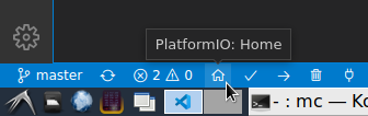
Для доступа к стартовому экрану PolatformIO можно воспользоваться двумя путями.
Путь первый:
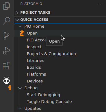
Путь второй:
Для создания нового проекта нажимается кнопка New Project:
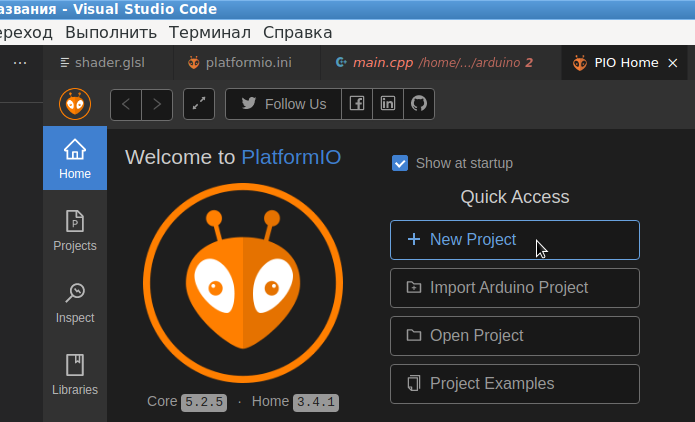
Для простоты, первый проект можно сделать с использованием библиотек Arduino. Библиотеки Arduino существуют не только для AVR-контроллеров, но и портированы на ARM-контроллеры, что обеспечивает практически такой же стиль написания кода, как и под всякие простые контроллеры вроде Arduino UNO.
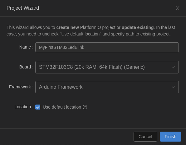
В качестве платы лучше выбрать BluePill F103C8 (Generic), во всяком случае именно с такой настройкой заработала китайская реплика. Чем настройки BluePill F103C8 (Generic) отличаются от STM32F103C8 (20k RAM, 64k Flash) (Generic) — непонятно, на первый взгляд это одно и тоже.
Примечание: информацию о других традиционных библиотеках, можно найти на странице:
https://docs.platformio.org/en/latest/boards/ststm32/bluepill_f103c8.html?utm_source=platformio&utm_medium=piohome
Обычно, для более низкоуровневого взаимодействия с железом контроллера, используется библиотека CMSIS.
В созданном проекте файл main.cpp необходимо привести к виду:
#include <Arduino.h>
#define LED_BUILTIN PC13
void setup() {
pinMode(LED_BUILTIN, OUTPUT);
}
void loop() {
digitalWrite(LED_BUILTIN, HIGH);
delay(250);
digitalWrite(LED_BUILTIN, LOW);
delay(250);
}
А файл platformio.ini, который находится в корне данного проекта, должен содержать следующие строки (здесь показаны настройки для китайской реплики STM32F103C8T6):
[env:bluepill_f103c8]
platform = ststm32
board = bluepill_f103c8
framework = arduino
; Change microcontroller
board_build.mcu = stm32f103c8t6
; Change MCU frequency
board_build.f_cpu = 72000000L
; Upload by stlink utility
upload_protocol = stlink
upload_flags = -c set CPUTAPID 0x2ba01477
; Setup debug server for China clone of STM32F103
debug_tool = stlink
debug_server =
openocd
-s /usr/share/openocd/scripts
-f interface/stlink.cfg
-c «transport select hla_swd»
-c «set CPUTAPID 0x2ba01477»
-f target/stm32f1x.cfg
-c «reset_config none»
board_debug.openocd_extra_args =
-c «set CPUTAPID 0x2ba01477»
Можно обратить внимание, что в данном конфиге даже можно задавать итоговую частоту, на которой должна работать плата. Правда, произвольное значение частоты задавать нельзя, т. к. для каждой платы существует ряд частот, которые она поддерживает в зависимости от возможности настройки делителей/умножителей (см. даташит). В данном конфиге задается максимальная штатная частота платы STM32F103C8T6 в 72MHz.
Компиляция, запуск, отладка
Если все сделано правильно, дальнейшие шаги должны производиться без проблем.
Компиляция, запуск и отладка производятся следующими кнопками:
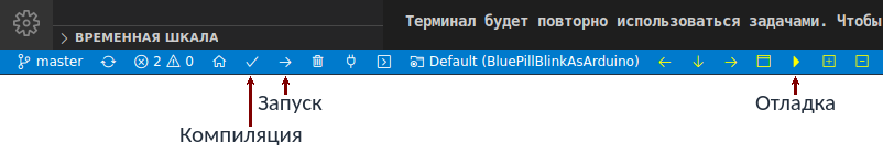
Под запускам понимается заливка (upload) бинарника на плату и запуск его на исполнение. В результате светодиод на плате STM32F103C8T6 должен замигать.
Перед запуском отладки рекомендуется установить брекпоинт на ту строку, в которой должен произойти останов. При срабатывании брекпоинта можно идти по алгоритму по шагам, или запустить выполнение до следующей точки останова, в общем все классические действия отладчика работают прямо на плате, и все это контролируется компьютером разработчика.

Topic: CS32F103C8T6 datasheet and tests (was:»UNEXPECTED idcode» flashing bluepill) (Read 34458 times)
0 Members and 1 Guest are viewing this topic.
Hi,
I bought an STM32F103C8T6 bluepill from aliexpress together with an ST-LINK V2. The st-link seems ok : I would reflash it with latest firmware using. The board has a chip which is not marked as ST STM32F103C8T6 but as CKS CS32F103C8T6 which seems to be advertised as a replacement clone.
When I try flashing using OCD, I get an error about a similar but not identic idcode (0x2ba01477 instead of 0x1ba01477):
>openocd -f interface/stlink-v2-1.cfg -f target/stm32f1x.cfg
GNU MCU Eclipse 64-bit Open On-Chip Debugger 0.10.0+dev-00352-gaa6c7e9b (2018-10-20-06:24)
Licensed under GNU GPL v2
For bug reports, read
        http://openocd.org/doc/doxygen/bugs.html
WARNING: interface/stlink-v2-1.cfg is deprecated, please switch to interface/stlink.cfg
Info : auto-selecting first available session transport "hla_swd". To override use 'transport select <transport>'.
Info : The selected transport took over low-level target control. The results might differ compared to plain JTAG/SWD
adapter speed: 1000 kHz
adapter_nsrst_delay: 100
none separate
Info : Listening on port 6666 for tcl connections
Info : Listening on port 4444 for telnet connections
Info : Unable to match requested speed 1000 kHz, using 950 kHz
Info : Unable to match requested speed 1000 kHz, using 950 kHz
Info : clock speed 950 kHz
Info : STLINK v2 JTAG v32 API v2 SWIM v7 VID 0x0483 PID 0x3748
Info : using stlink api v2
Info : Target voltage: 3.213236
Warn : UNEXPECTED idcode: 0x2ba01477
Error: expected 1 of 1: 0x1ba01477
in procedure 'init'
in procedure 'ocd_bouncer'
It seems that the CKS clone is not reporting the proper idcode, but when I run the stlink utility, it recognises the mcu as an STM32F10XX (see attachment)
Is there something I did wrong ? Is the idcode in the latest stable OpenOCD wrong for stm32f103 ? Something weird with the clone ?
Thank you,
John.
« Last Edit: January 24, 2019, 07:59:55 am by Jaunedeau »

Logged
The difference is the revision has changed for the SW-DP ID. It isn’t identifying the uC itself. You can work around it by adding «set CPUTAPID 0x2ba01477» to the cfg file. Probably should just make a cs32f1x.cfg for it. The ST-Link tool is either ignoring the DPIDR entirely or masking off the revision bits so doesn’t care. It identifies the uC by reading a different field.
Hmm. Interesting. First time I’ve seen this compatible clone. It used to just be GigaDevices with their GD32 compatible clones but now there is this CKS CS32 as well it seems. I wonder if it is the same arrangement with a standalone flash die bonded to the uC die inside the package. It isn’t a clone of the STM32 silicon since it has some differences like this SW-DP DPIDR change.
Does anyone have a link to the datasheet for this new device ?
I’ve ordered 2 BluePills which claim to use it, just to see how compatible it is with the STM32
IMHO the GD32 isn’t quite as compatible as it first seemed to be, because it had extended features using Reserved bits in various control registers, which could result in unexpected behaviors. And the zero wait state instruction execution because the flash was mirrored into RAM, could also cause timing problems
etc
Logged
I did not search for too long, but didn’t find the datasheet.
I seems that the manufacturer is China Key System & Integrated Co. Ltd, but the CK32F103 is not listed on their website : http://www.cksic.com/en/IC/234.html
I sent an email to them bu did not receive an answer. If you manage to find something please post it in this topic, I will change the topic accordigly 
Logged
IMHO the GD32 isn’t quite as compatible as it first seemed to be,
My cheap is marked CS32, not GD32, I don’t know if they are the same chips.
« Last Edit: January 24, 2019, 08:08:22 am by Jaunedeau »
Logged
Thanks to @Just4Fun on the stm32duino.com forum , here is a link to the datasheet
http://www.ckscup.com/upload/CS32F103%E6%89%8B%E5%86%8C.pdf
Unfortunately its in Chinese, and its too big for Google translate to convert
One point of interest is that the claimed SRAM size is 64k, in the datasheet for the CS32F103C8 version whereas the STM32F103C8 only has 20k
However its possible that the cut and pasted the whole datasheet from the Chinese version of the STM32F103 series and didn’t bother to update individual values to match what the C8 version has.
Logged
Great news
One point of interest is that the claimed SRAM size is 64k, in the datasheet for the CS32F103C8 version whereas the STM32F103C8 only has 20k
However its possible that the cut and pasted the whole datasheet from the Chinese version of the STM32F103 series and didn’t bother to update individual values to match what the C8 version has.
I can test that tomorrow
Logged
OK
FYI.
I’m currently trying to get the datasheet PDF translated using Chrome.
It will probably end up as a html page, so won’t be perfect, but will be better than nothing
Logged
Its not perfect, as its lost some formatting, but here is a link to the PDF of the datasheet which I converted to HTML then ran a translator on, and then saved back as a PDF
https://drive.google.com/open?id=1dsH1QbDJNRaqphIb7adMx-BliQag9xj0
BTW. I don’t think this the correct place for this thread.
Moderators please more it somewhere more appropriate.
Logged
One point of interest is that the claimed SRAM size is 64k, in the datasheet for the CS32F103C8 version whereas the STM32F103C8 only has 20k
However its possible that the cut and pasted the whole datasheet from the Chinese version of the STM32F103 series and didn’t bother to update individual values to match what the C8 version has.
I can confirme that I could acces an array of 4803 u32, but not an array of 5003 u32 (the code is compiled in Rust, the led blinking and loops probably take more than the 468 bytes that should be left).
Logged
Chinese seller say the folowing
CS32F103C8T6 QFP48 completely replaces STM32F103C8T6 PIN TO PIN spot
Logged
I can confirme that I could acces an array of 4803 u32, but not an array of 5003 u32 (the code is compiled in Rust, the led blinking and loops probably take more than the 468 bytes that should be left).
Did you alter the linker script?
Logged
I can confirme that I could acces an array of 4803 u32, but not an array of 5003 u32 (the code is compiled in Rust, the led blinking and loops probably take more than the 468 bytes that should be left).
Did you alter the linker script?
I think I did, but later found that another linked script comes the hardware abstraction layer I use (and this one if automatically downloaded at build so I still have to test using a local modified copy)
Logged
Trying to declare large arrays into RAM would not necessarily be a valid test, even if you changed the linker settings, unless you then wrote and read back the array
A much simpler way is just to use a pointer to the start of RAM and and write and read back a byte then increment the pointer until you no longer get the correct value.
In fact you should write 2 different values e.g. 0x55 and 0xaa or 0xff and 0x00 (I prefer the former), in case you read back either 0x00 or 0x00 when there is undefined memory
I guess perhaps rust does not allow this, but I think you are making life difficult for yourself by not using C, since this is an unknown processor, and AFIK rust on embedded is not as stable as C on embedded.
Logged
Now I’m curious why you bought the CS32F103C8T6.
Is it really worth saving a few cents and stuggling with the incompatibilies and differenced compared to the STM32F103C8T6?
If you were represenenting a big company and expecting to sell millions of these could underdstand, but then you would have better leverage to get datasheets directly from the manufacturer.
There is also some info on the CS32 thingie on stm32duino.com.
Oops, I think that was about the GDS32F…. Are those the same?
Logged
GD32 and CS32 appear to be different devices
I think the OP bought a BluePill board which he expected to use a STM32 but has a CS32 on it
I deliberately ordered some of the CS32 boards as a matter of general interest
Logged
I think the OP bought a BluePill board which he expected to use a STM32 but has a CS32 on it
Exactly, I like to order the cheapest parts on aliexpress and see what happens. This is how I learned to usemy oscilloscop
Logged
I received my CS32F103C8 (BluePill) boards yesterday
I did some tests and had no problem flashing using my ST-Link as the device reported the same ID code as a STM32F103C8 (0x410)
Except ST-Link reported the CS32F103C8 had 128k Flash and it reports the STM32F103C8 has 64k Flash (even though the STM32F103C8 actually has 128k)
I wrote a 128k file of random bytes (e.g. from dev/random) and verified that the whole file had been written to Flash. So the CS32F103C8 definitely appears to have 128k Flash
I tried changing the linker settings to increase the amount of RAM for a test application, but the application would not run if I changed the RAM size to more than the 20k which the STM32F103C8 has.
I also wrote some code to try to access RAM above the 20k boundary, and the code asserted, which again validates that the CS32F103C8 has the same 20k RAM size as the STM32F103C8
I’ve not done any more testing apart to install a USB bootloader and an application that used USB and the GPIO connected to PC13 and that all worked OK.
How is it with overclocking?
Logged
It’s important to try new things..
I tried running a «blink» application at 128Mhz overclock , but it failed.
However this isn’t conclusive, as I’d need to confirm whether the same application works OK on a STM32, in case I screwed up with the test.
Logged
128MHz overclock is a standard option in your core, you would need an usb serial dongle however. Serial1 based tests should work fine @128M (with stm32).
« Last Edit: February 08, 2019, 06:48:49 pm by imo »
Logged
It’s important to try new things..
Yes.
I know it has the 128Mhz option
Thats what I tried and blink didnt seem to work, but I need to setup and check the same sketch on a STM32 BP just to confirm that the CS32 does not work at 128Mhz
Logged
Interesting
The CS32 does not overclock very well
I added some more overclocking settings to my Core to do this testing.
And a STM32 BluePill worked fine right up to 128Mhz (16 multipler on the 8Mhz crystal)
But the fastest I could run the CS32 at was 80 Mhz (x 10 multiplier)
I checked the bit pattern for the x 10 vs x11 multipliers and the values are
RCC_PLLMUL_10 = (0x8 << 18),
RCC_PLLMUL_11 = (0x9 << 18),
So this doesn’t look like they simply reduced the number of bits in that the PLL has.
It simply looks like it won’t run as fast.
Note the GD32, runs fine at 120Mhz, so the CS32 probably isn’t based on the GD32
Logged
the fastest I could run the CS32 at was 80 Mhz
Could this mean the CS32 has lower headroom for high temperature operation?
The translated datasheet doesn’t address operating temperature (or power consumption!), whereas the STM32F103 datasheet lists all of this in Table 9 (General operating conditions), giving a range of -40 to 85/105 °C depending on model.
Logged
Yeah, all my stm32f103xx work fine at 128M. GD is flash-less chip so it may run even faster.
With the CS clone you may try to increase its number of flash wait states to achieve a higher clock. The default setting would be 2, try it with 3.
PS: you may add the «Number of flash WS» selection into your core
« Last Edit: February 10, 2019, 11:40:21 am by imo »
Logged
It’s important to try new things..
The following users thanked this post: Yansi
|
1 / 1 / 0 Регистрация: 26.11.2017 Сообщений: 118 |
|
|
1 |
|
Тест дебага не работает24.07.2019, 18:42. Показов 8544. Ответов 4
я использую плагин VisualGDB для разработки в Visual Studio 2017, микроконтроллер STM32F103C8T6, и ST-Link v2. дебаг я делаю через OpenOCD, использую дефолтный протокол. я пытаюсь при создании проекта провести тестирование дебага, но у меня выдаётся ошибка error expected 1 of 1 0x1ba01477. что делать? вот полный лог: C:UsersМихаилAppDataLocalVisualGDBEmbeddedDe bugPackagescom.sysprogs.arm.openocdbinopenocd.e xe -c «gdb_port 62740» -c «telnet_port 62741» -f interface/stlink-v2.cfg -f target/stm32f1x.cfg -c init -c «reset init» -c «echo VisualGDB_OpenOCD_Ready»
__________________
0 |

|
3024 / 1528 / 191 Регистрация: 28.10.2011 Сообщений: 5,612 Записей в блоге: 6 |
|
|
24.07.2019, 19:23 |
2 |
|
STM32F103C8T6 Точно STM32F103C8T6, а не китайская подделка именуемая CS32F103C8T6?
0 |

|
1 / 1 / 0 Регистрация: 26.11.2017 Сообщений: 118 |
|
|
24.07.2019, 19:43 [ТС] |
3 |
|
Точно STM32F103C8T6, а не китайская подделка именуемая CS32F103C8T6? да, я только сейчас узнал, это китайская подделка((( и как теперь убрать ошибку?
0 |
|
6681 / 2664 / 366 Регистрация: 17.02.2013 Сообщений: 3,906 |
|
|
24.07.2019, 21:33 |
4 |
|
РешениеВот что пишут по поводу аналогичного твоему случая (ссылку не могу дать, тут запрещено давать ссылки на другие форумы) : —Ok so after quite a few hours of research, this seems to have solved my problem: Edit the .cfg file in the project folder and add the following line: But this has to be removed to program devices with the normal idcode.—
1 |
 Сообщение было отмечено Annigilyator98 как решение
|
Администратор
9357 / 4639 / 755 Регистрация: 17.04.2012 Сообщений: 9,490 Записей в блоге: 14 |
|
|
25.07.2019, 08:56 |
5 |
|
Ethereal, вы можете давать ссылки на англоязычные форумы, но ответ или его часть должна находится в сообщении на нашем форуме.
0 |
|
IT_Exp Эксперт 87844 / 49110 / 22898 Регистрация: 17.06.2006 Сообщений: 92,604 |
25.07.2019, 08:56 |
|
Помогаю со студенческими работами здесь
Не работает тест interface uses Ошибка работы дебага Не работает тест на html Искать еще темы с ответами Или воспользуйтесь поиском по форуму: 5 |