I am getting this PHP error, what does it mean?
Notice: Undefined offset: 0 in
C:xampphtdocsmywebsitereddit_vote_tutsrcvotes.php on line 41
From this code:
<?php
include("config.php");

function getAllVotes($id)
{
    $votes = array();
    $q = "SELECT * FROM entries WHERE id = $id";
    $r = mysql_query($q);
    if(mysql_num_rows($r)==1)//id found in the table
    {
        $row = mysql_fetch_assoc($r);
        $votes[0] = $row['votes_up'];
        $votes[1] = $row['votes_down'];
    }
    return $votes;
}

function getEffectiveVotes($id)
{
        $votes = getAllVotes($id);
        $effectiveVote = $votes[0] - $votes[1];    //ERROR THROWN HERE
        return $effectiveVote;
}

$id = $_POST['id'];
$action = $_POST['action'];

//get the current votes
$cur_votes = getAllVotes($id);

//ok, now update the votes

if($action=='vote_up') //voting up
{

    $votes_up = $cur_votes[0]+1;     //AND ERROR THROWN HERE


    $q = "UPDATE threads SET votes_up = $votes_up WHERE id = $id";
}
elseif($action=='vote_down')
{
    $votes_down = $cur_votes[1]+1;
    $q = "UPDATE threads SET votes_down = $votes_down WHERE id = $id";
}

$r = mysql_query($q);
if($r)
{
    $effectiveVote = getEffectiveVotes($id);
    echo $effectiveVote." votes";
}
elseif(!$r) //voting failed
{
    echo "Failed!";
}
?>
![]()
asked Jul 1, 2011 at 14:51
![]()
4
You are asking for the value at key 0 of $votes. It is an array that does not contain that key.
The array $votes is not set, so when PHP is trying to access the key 0 of the array, it encounters an undefined offset for [0] and [1] and throws the error.
If you have an array:
$votes = array('1','2','3');
We can now access:
$votes[0];
$votes[1];
$votes[2];
If we try and access:
$votes[3];
We will get the error «Notice: Undefined offset: 3»
![]()
toddmo
19.8k13 gold badges91 silver badges102 bronze badges
answered Jul 1, 2011 at 14:55
![]()
YonoRanYonoRan
1,6989 silver badges7 bronze badges
6
first, check that the array actually exists, you could try something like
if (isset($votes)) {
   // Do bad things to the votes array
}
![]()
answered Mar 24, 2014 at 8:36
![]()
This answer helped me https://stackoverflow.com/a/18880670/1821607
The reason of crush — index 0 wasn’t set. Simple $array = $array + array(null) did the trick. Or you should check whether array element on index 0 is set via isset($array[0]). The second variant is the best approach for me.
![]()
answered Dec 1, 2015 at 10:17
![]()
Use print_r($votes); to inspect the array $votes, you will see that key 0 does not exist there. It will return NULL and throw that error.
![]()
answered Jul 23, 2011 at 9:59
![]()
0
getAllVotes() isn’t returning an array with the indexes 0 or 1. Make sure it’s returning the data you want by calling var_dump() on the result.
answered Jul 1, 2011 at 14:54
![]()
Tim CooperTim Cooper
156k38 gold badges325 silver badges276 bronze badges
I encountered this as well and the solution is simple, dont hardcode the array index position in your code.
Instead of
$data[0]['somekey'] do
foreach($data as $data_item)

{

echo $data_item['somekey'];

}
If there is an array or more you can perform your desired action inside the loop, but if it’s undefined it will not bring an error. you can also add other checks on top of that.
You could also add a variable and increment it in a for in loop to limit your looping if you want only the first positions or something.
answered Jul 29, 2018 at 12:50
![]()
MihaiMihai
821 silver badge6 bronze badges
As explained it happens because there is no data in the $cur_votes[0] and hence it throws an error.
To ensure your code works fine, before performing "$votes_up = $cur_votes[0]+1;" echo the $cur_votes[0] value to see if there is any value stored or not.
Surely, there is no value stored.
![]()
answered Mar 27, 2013 at 9:00
![]()
EspantaEspanta
1,0501 gold badge17 silver badges27 bronze badges
function getEffectiveVotes($id)
According to the function header, there is only one parameter variable ($id).
Thus, on line 27, the votes[] array is undefined and out of scope. You need to add another
parameter value to the function header so that function getEffectiveVotes() knows to expect two parameters. I’m rusty, but something like this would work.
function getEffectiveVotes($id, $votes)
I’m not saying this is how it should be done, but you might want to research how PHP
passes its arrays and decide if you need to explicitly state to pass it by reference
function getEffectiveVotes($id &$votes) <---I forget, no time to look it up right now.
Lastly, call function getEffectiveVotes() with both arguments wherever it is supposed to be called.
Cheers.
answered Jun 21, 2013 at 3:46
![]()
Anthony RutledgeAnthony Rutledge
6,5221 gold badge36 silver badges44 bronze badges
As you might have already about knew the error. This is due to trying to access the empty array or trying to access the value of empty key of array. In my project, I am dealing with this error with counting the array and displaying result.
You can do it like this:
if(count($votes) == '0'){

    echo 'Sorry, no votes are available at the moment.';
}
else{
    //do the stuff with votes
}
count($votes) counts the $votes array. If it is equal to zero (0), you can display your custom message or redirect to certain page else you can do stuff with $votes. In this way you can remove the Notice: Undefined offset: 0 in notice in PHP.
answered Feb 19, 2016 at 5:33
![]()
VijayRanaVijayRana
9131 gold badge12 silver badges35 bronze badges
If you leave out the brackets then PHP will assign the keys by default.
Try this:
$votes = $row['votes_up'];
$votes = $row['votes_down'];
answered Sep 22, 2014 at 19:07
![]()
DavidDavid
4292 gold badges5 silver badges14 bronze badges
In my case it was a simple type
$_SESSION['role' == 'ge']
I was missing the correct closing bracket
$_SESSION['role'] == 'ge'
answered Nov 23, 2018 at 7:44
![]()
Hammad KhanHammad Khan
16k16 gold badges111 silver badges134 bronze badges
If you are using dompdf/dompdf and error occure in vendor/dompdf/dompdf/src/Cellmap.php then
It looks like we’re using the wrong frame id in the update_row_group method. Initial testing seems to confirm this. Though that may be because this is strictly a paged table issue and not too many of the documents in my test bed have paged tables.
Can you try changing line 800 to:
$r_rows = $this->_frames[$g_key][«rows»];
($g_key instead of $r_key)
https://github.com/dompdf/dompdf/issues/1295
answered Dec 19, 2018 at 7:51
![]()
Use mysql row instead
mysql_fetch_row($r)
Meanwhile consider using mysqli or PDO
?>
Try seeding data with command: php artisan db:seed.
![]()
sssurii
7264 silver badges15 bronze badges
answered Jul 26, 2021 at 4:09
![]()
Nam SamaNam Sama
3253 silver badges5 bronze badges
0
its just a warning use:
error_reporting(0);
it shows when we do not initialize array and direct assigning value to indexes.
somefunction{
$raja[0]="this";
$raja[1]="that";
}
instead :
somefunction{
$raja=array(0=>'this',1='that');
//or
$raja=array("this","that");
}
it just notification, do not generate any output error or any unexpected output.
answered Aug 27, 2014 at 7:59
![]()
3
Main Content
This example shows how offset error and gain error are calculated and how each affects the transfer curve of an ADC. Offset error and gain error characterize part of the linearity error in an ADC.
Offset error is the difference between the center of the least significant code and the center of the same code on an ideal ADC with the same number of bits. Offset error is usually reported in units of the least significant bit (LSB) of the converter. One LSB is equivalent to the converter’s quantization interval.
Gain error in LSB is the difference between the center of the most significant code after offset error correction and the center of the same code on an ideal ADC with the same number of bits.
Due to the difficulty in determining the precise location of the center of a code with a non finite boundary, these values are most commonly measured with respect to the first and last threshold of the converter, respectively.
Units for Offset Error and Gain Error
The unit  , which is used in this example, is defined as:
Thus, an error in  (volts) translates into as follows:
where  is the full scale range of the ADC and
  is the number of bits of the ADC.
Linearity errors are also commonly reported in normalized units with respect to the full scale range:
Another unit sometimes used for linearity errors used is percent full scale. Percent full scale is defined as normalized units multiplied by 100:
Calculate Offset Error and Gain Error
Use a 3-bit ADC with dynamic range [-1 1]. Define an offset error of 1 LSB and a gain error of 1 LSB.
Nbits = 3;
Range = [-1 1]; % ADC Full Scale Range
OffsetError = 1;
GainError = 1;
LSB = (max(Range) - min(Range)) / (2^Nbits - 1);
The digital codes from the ideal ADC are identical to those from the experimental ADCs.
[TC0Analog, TC0Digital] = og2tc(Nbits, Range, 0, 0); % Ideal ADC Transfer Curve
TC1Analog = og2tc(Nbits, Range, OffsetError, 0); % Offset Error Only
TC2Analog = og2tc(Nbits, Range, 0, GainError); % Gain Error Only
TC3Analog = og2tc(Nbits, Range, OffsetError, GainError); % Both Offset Error and Gain Error
plotAdcTcForExample(TC0Digital, TC0Analog, TC1Analog, TC2Analog, TC3Analog, Nbits);
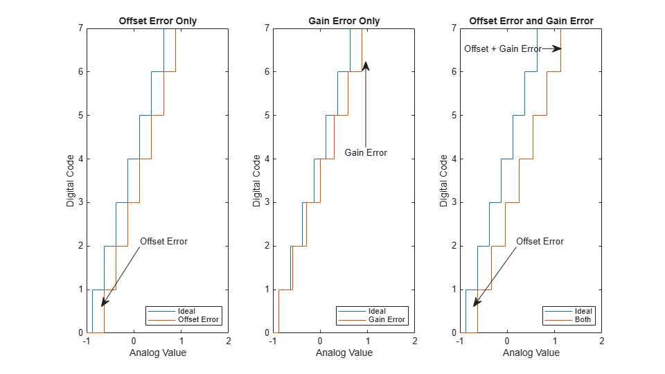
The sum of offset error and gain error is known as full-scale error. In monopolar converters zero error, essentially offset error defined at analog level 0, is identical to regular offset error. In bipolar converters such as those above, offset error and zero error are different quantities.
Use of Linearity Errors as Impairments
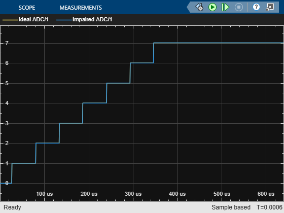
Compare a flash ADC with offset and gain error to one with no impairments.
model = 'OffsetGainExample';
open_system(model);
open_system([model '/Time Scope']);
sim(model);
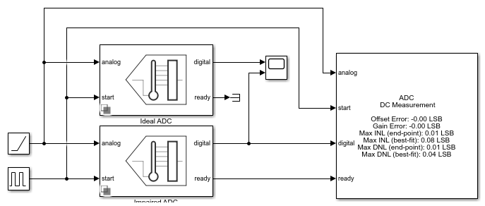
The ADC DC Measurement block confirms the values of the impairments to within a margin of error determined by the sample rate of the system. The offset error and gain error were both entered as 1 LSB. Offset error was measured as 1.08 LSB and gain error was measured as 0.97 LSB. Errors in these measurements are due to the converter not sampling exactly at its threshold values. The maximum expected error in LSB is:
where  is the slope of the input ramp/sawtooth signal in LSB/s, and
  is the ADC’s conversion start frequency.
See Also
Flash ADC | ADC DC Measurement
- Trial Software
- Trial Software
- Product Updates
- Product Updates

Topic: Cannot zero offset error on Unigor A43 analog multimeter (Read 1237 times)
0 Members and 1 Guest are viewing this topic.
I have just purchased a Unigor A43 analog multimeter. It is in really good condition, but I cannot adjust it to zero with the offset screw below the meter scale. The lowest possible adjustment is about 5 on the 100 scale or 1.5 on the 30 scale, see picture (note, same result in off position). In the photos from the seller, however, the meter was adjusted to zero, and seller confirms it was fine prior to shipping. Needle does not look bent.
I suspect damage during transport due to tossing/bad handling. There were some further evidence of that: part of the outer box has been torn and taped by shipment company, the meter case has some cracks in two corners which seller claims was not there, and the strap around the meter inside its carry case is partly cracked as if it has been stretched.
I have tried measuring with the meter, and it works quite accurately across the ranges, except for the offset error. Also, the needle is not physically constrained, i.e., it can go towards zero/beyond when getting a small and safe negative signal.
When lying on its sides, exposed to gravity, the needle will move to close to zero on one side, and 10 on the 100 scale when lying on the other side — i.e., symmetrical movement around the «offset» of 5 on 100 scale.
Anyone with experience in analog meters with an opinion on what could be the cause? Is it likely that the meter has been damaged due to excessive force during transportation? Anything that can be done, or checked to verify the cause? Could it be balancing weights?
When taking apart, there is another adjustment screw on the backside of the meter casing, but I have not tried adjusting that yet — could it be a further range for offset adjustment on the front?
Thanks,
Peter
« Last Edit: June 26, 2022, 08:42:31 pm by pbs74 »

Logged
Meter movements typically have spiral springs. Imagine a vinyl LP of extremely short playing time. Try to see if excessive mechanical shock has resulted in adjacent turns getting caught together. If they have it may be relatively easy to separate them.
« Last Edit: June 26, 2022, 09:44:07 pm by wasedadoc »
Logged
If there is no evidence of spring damage, then bend the pointer slightly at its base. Or adjust the spring. While these are delicate things, they are not very precise so you won’t cause any trouble.
Another way is to bend the two ears that engage the zero corrector screw.
Logged
Some more details after «taking it apart» 
I’ve managed to zero it in (image 1) by moving the blue wire a bit (image 2), so it measures correctly across ranges. However, the new zero position means the zero adjustment screw/tap does not fit anymore, which is kind of annoying when assembled (image 3).
I wonder if the zeroing plate has somehow been skewed vs the metering base (close up images 4 and 5). I’ve tried to put light pressure on the zeroed plate while holding the base metal parts, but nothing moves, and I do not want to turn too hard, these are delicate things (notice the very, very thin string from the needly mount to the top place, through the hole the zeroing plate is centered around).
Anyone with some further suggestions based on the close-ups? Worst case I would be able to assemble without the zero adjustment screw and poke with a small screwdriver (or maybe non magnetic plastic piece), but would be a lot nicer making it work like it should, so help much appreciated.
Meter movements typically have spiral springs […] Try to see if excessive mechanical shock has resulted in adjacent turns getting caught together.
I do not see any spiral springs, maybe covered under the «zeroing plate» at its center/mount?
If there is no evidence of spring damage, then bend the pointer slightly at its base. Or adjust the spring. While these are delicate things, they are not very precise so you won’t cause any trouble.
Might work, but with above zeroing progress, I am not too keen on bending needle, as it will introduce some non-linearity across the different scales (although probably negligible). I will say it is pretty precise though, see accuracy examples in images 6-8 vs Brymen 829 (and keeping in mind that my zeroing is not dead on, but half a needle thickness off, see first image).
Another way is to bend the two ears that engage the zero corrector screw.
I think this would have been ideal, had these «ears» been of metal and not something resembling thin pcb.
Logged
I do not see any spiral springs, maybe covered under the «zeroing plate» at its center/mount?
There must be something that acts against the clockwise rotation of the pointer. Apart from making the pointer move back to zero when no current is flowing it is that anticlockwise force which should be directly proportional to the degree of clockwise rotation of the pointer which determines the linearity of the device. The meter seems to need only 30 microAmps for full scale deflection which means that the clockwise force from the coil and magnet are quite weak and thus the anticlockwise force will be equally weak, meaning a very weak spring. Often the forked piece that is turned by the front zeroing screw is attached to one end of a spiral spring. In this case there appears to be a wire going vertically downwards from a solder joint that rotates with the forked arm. Possibly that is a spring which is operating in torsion mode. Can you rotate the brown forked piece to have its slot at the 6 o’clock 3 o’clock (see my next post below) position while holding the metal piece with that solder joint to remain in the position shown in the photo? I mean is it just friction that makes the two move together when the front adjusting screw is turned?
« Last Edit: June 28, 2022, 09:41:46 am by wasedadoc »
Logged
With very sensitive meters the restoring force can be from just the torsion of the wire holding the coil in place and providing the current.
Logged
The following users thanked this post: pbs74
Hello Peter,
as i see, there is missing a part for zeroing by small screwdriver.
In the hole, marked with <0> has to be a special screw with an excentric pin on the other side.
This pin changes the position of the fork-like wing from hard paper.
With open instrument, you can use a big screwdriver and put it in the gap and move it slightly to zero the instrument.
Best regards
Frank
Logged
No, it is not missing. It is clearly visible in the photo of the front of the multimeter in the first post.
However, now that I have looked at that photo more carefully I realise that the zeroing screwdriver slot is displaced to the right of the centre of the meter. So my mention of 6 o’clock position on the forked arm was incorrect. Can the spigot on the adjustment screw not engage in the fork slot when the forked arm is in the position which moves the pointer to zero on the scale?
« Last Edit: June 28, 2022, 09:13:51 am by wasedadoc »
Logged
Okay, i see it in the first phot, my mistake.
You have to «lock» the pin of the adjustment screw into the fork,
then you can zero your instrument.
So you have to change the position of the fork slightly ond to rotate the screw until it fits.
Maybe the previous owner changes the fork position accidentally when opening the unit
and so the pin of the screw rotates outside the fork.
Best regards
Frank
Logged
With very sensitive meters the restoring force can be from just the torsion of the wire holding the coil in place and providing the current.
Yes, from the photos that’s a taut band movement, there are no hair springs or pivots to be adjusted.
Yes, it is easy to get the offset pin in the adjustment screw misaligned with the slot in the adjuster — a good indication though, is that the needle can be adjusted in one direction but stays there when you try to adjust it back (on no opposite side of the slot to pull it back).
Do not attempt to bend the pointer, as somebody suggested! The pointers are made of very thin walled Aluminium tube and will kink if you attempt to bend it. You will almost certainly snap the suspension band too. Bending the needle will also throw the movement completely out of balance, meaning that the zero position will vary wildly with the meter orientation.
Try moving the meter into various orientation and see if the needle ‘zero’ point remains reasonably constant. This will indicate whether anything has been bent in transit and upset the balance of the movement.
All movements have a means of adjusting the zero adjustment range. This is in the form of an adjuster on the bottom end of the suspension — either the bottom hairspring mounting, or in this case, the other suspension band support. This is also moveable (although it doesn’t have the same long adjustment lever. The correct procedure is to set the top zero adjuster to mid position, and then rotate the bottom one to bring the pointer to approximate zero position.
The ease of adjusting the bottom adjuster depends on the constuction of the meter. You will probably need a long needle (non magnetic), or may even need to remove the scale plate to get access. One of the movement connecting wires will be soldered to this bottom adjuster — the wire getting accidentally tugged can be one reason for the problem occuring.
EDIT. On some movements, there is a fricton fit between the adjustment lever and the actual spring / band mount. Looking at the photos, I notice that the lever is phenolic, so it may be possible to move it in relation to the top band mount. This could have go misaligned by the a previous owner (in fact, it looks to be the case).
« Last Edit: June 28, 2022, 10:04:53 am by Gyro »
Logged
Best Regards, Chris
«Victor Meldrew, the Crimson Avenger!»
The following users thanked this post: harrimansat, pbs74
EDIT. On some movements, there is a fricton fit between the adjustment lever and the actual spring / band mount. Looking at the photos, I notice that the lever is phenolic, so it may be possible to move it in relation to the top band mount. This could have go misaligned by the a previous owner (in fact, it looks to be the case).
Yes, that friction is what I asked about in one of my posts above.
Logged
Ah yes, I missed that part of your comment.
Looking at the 5th photo, you can clearly see that the forked lever is actually made up of 2 sheets of phenolic, one above the other, with the brass (more likely phosphor bronze) sheet holder for the end of the taut band sandwiched between them. A sure sign of a friction coupling. By holding one of the two small brass tabs (not the one tensioning the the band), and moving the forked levers, keeping them parallel, they will move relative to each other.
I had the same situation with a single spring electrostatic voltmeter a few weeks ago and it wasn’t immediately obvious that there were two parallel metal forked levers.
« Last Edit: June 28, 2022, 03:22:51 pm by Gyro »
Logged
Best Regards, Chris
«Victor Meldrew, the Crimson Avenger!»
The following users thanked this post: pbs74
Thanks for all the good comments, getting closer. Let me reply on a few, and fill in some of the gaps so far.
The meter seems to need only 30 microAmps for full scale deflection which means that the clockwise force from the coil and magnet are quite weak and thus the anticlockwise force will be equally weak, meaning a very weak spring.
According to manual it is even as low as 8.8microAmps
No, it is not missing. It is clearly visible in the photo of the front of the multimeter in the first post.
However, now that I have looked at that photo more carefully I realise that the zeroing screwdriver slot is displaced to the right of the centre of the meter. So my mention of 6 o’clock position on the forked arm was incorrect. Can the spigot on the adjustment screw not engage in the fork slot when the forked arm is in the position which moves the pointer to zero on the scale?
Correct, that is the issue now, it seems I was not clear earlier. I do indeed have the adjustment screw (see new image 11 showing backside tap on screw). However, I took it out to show how it will not fit correctly in the adjustment slot once the adjustment lever is a position where the meter is zeroing. This is my main issue at this point (in first post, I could not zero it, but that is at least possible now, but will not allow using screw). I’ve updated image 4a showing the adjustment lever outline and the travel of the adjustment screw.
Okay, i see it in the first phot, my mistake. You have to «lock» the pin of the adjustment screw into the fork, then you can zero your instrument. So you have to change the position of the fork slightly to rotate the screw until it fits.
Thanks Frank, unfortunately screw will not fit the fork once latter is set to zero meter, see above.
In this case there appears to be a wire going vertically downwards from a solder joint that rotates with the forked arm. Possibly that is a spring which is operating in torsion mode.
Good with a confirmation, that is how I interpreted it as well based on looking at needle and wire while turning zeroing arm. Only heard of spirals before, never worked with analog meters inside.
Try moving the meter into various orientation and see if the needle ‘zero’ point remains reasonably constant. This will indicate whether anything has been bent in transit and upset the balance of the movement.
It does not. With the original «zero» at 5 on 100 scale lying flat on table, putting it on one side would move needle to 0 and putting it on the opposite side move needle to 10. Not sure if that is enough for it to be out of balance from transit, or it is just very delicate/accurate. It is made for use only lying flat.
Can you rotate the brown forked piece to have its slot at the 6 o’clock 3 o’clock (see my next post below) position while holding the metal piece with that solder joint to remain in the position shown in the photo?
This is exactly what I already tried: gently holding back either the left «ear» or the top part that wire is solder on to with a nail while turning. See updated image 3a with arrows. Nothing moved, but I did it very gently to not break anything so might not have used enough force?
All movements have a means of adjusting the zero adjustment range. This is in the form of an adjuster on the bottom end of the suspension — either the bottom hairspring mounting, or in this case, the other suspension band support. This is also moveable (although it doesn’t have the same long adjustment lever. The correct procedure is to set the top zero adjuster to mid position, and then rotate the bottom one to bring the pointer to approximate zero position.
The ease of adjusting the bottom adjuster depends on the construction of the meter. You will probably need a long needle (non magnetic), or may even need to remove the scale plate to get access. One of the movement connecting wires will be soldered to this bottom adjuster — the wire getting accidentally tugged can be one reason for the problem occuring.
There is in fact a screw on the backside of the meter scale, inside the multimeter — see new images 9 and 10. It is made for adjustment, as there is a hole in the pcb to reach it. It has been fixed in position with (white) lacquer. Looking at the screw there is a something going through it, it might very well be an anchor for fixing the torsion spring. I did not touch this screw at I did not know what it was for. If indeed used to set zero range for the front zero adjustment, should I try turning this screw, or instead apply more force on the front adjustment lever while holding back the metal parts, to overcome the friction hold?
Logged
Given that the meter is quite low current the sensitivity to orentation does not look too bad. It does not nned that mcch extra weight at the pointer or counter-weight to cause that imbalance.
For the srew at the back, it may be the point for a coarse zero adjustment, but could also adjust the position / hight and worst case hold the wire / spring. At least I can’t tell for sure.
Logged
The following users thanked this post: pbs74
Try moving the meter into various orientation and see if the needle ‘zero’ point remains reasonably constant. This will indicate whether anything has been bent in transit and upset the balance of the movement.
It does not. With the original «zero» at 5 on 100 scale lying flat on table, putting it on one side would move needle to 0 and putting it on the opposite side move needle to 10. Not sure if that is enough for it to be out of balance from transit, or it is just very delicate/accurate. It is made for use only lying flat.
It’s probably close enough, balancing is seldom perfect and yes, it will be intended to operate lying flat. I suspect that the suspension band would probably snap before anything bent during transit anyway.
There is in fact a screw on the backside of the meter scale, inside the multimeter — see new images 9 and 10. It is made for adjustment, as there is a hole in the pcb to reach it. It has been fixed in position with (white) lacquer. Looking at the screw there is a something going through it, it might very well be an anchor for fixing the torsion spring. I did not touch this screw at I did not know what it was for. If indeed used to set zero range for the front zero adjustment, should I try turning this screw, or instead apply more force on the front adjustment lever while holding back the metal parts, to overcome the friction hold?
I’m nervous of the screw if I can’t fully see what it is attached to. It may be fixed to the bottom band attachment, but it looks quite a big screw. A more likely possibility is that it presses on the bottom attachment, raising and lowering it to adjust the clearance between the needle and the scale (possibly tension too). If the laquer isn’t disturbed then it obviously hasn’t been disturbed to cause the problem.
My bet is still on the friction hold between the lever and the top attachment. Avoid Hold#1! The most likely result would be snapping the suspension band, changing the tension, or misaligning it from the vertical. Hold#2 is the correct place, it is the same piece of metal but can only rotate around the axis. Look for signs of white laquer (hopefully disturbed). One thing you could try is gently moving one of the forked levers relative to the other (don’t snap the forks) that might free things up a bit — Hold#2 can only follow one of them, that’s the side that’s sticking and you can then hopefully ease that more easily.
Sorry, it’s a lot easier to do first hand (and know when I’m applying safe pressure) than to describe to someone else — I would feel bad if a tool slips and you destroy the movement.
Logged
Best Regards, Chris
«Victor Meldrew, the Crimson Avenger!»
The following users thanked this post: pbs74
One normally does not have to adjust the mechanical zero of the movement very often. With age the zero should become even more stable. So one may be able to live without the easy adjustment from the front.
Logged
The following users thanked this post: Gyro, pbs74
Yes, that’s certainly a viable option if things don’t free up easily and you don’t want to force them. I’m not sure off-hand whether a taut band suspension will have a more stable zero than a traditional one, it only has one restoring element involved rather than a pair of coil springs, and of course no bearing friction.
I can’t see from the photos whether it would be possible to replace the zero adjustment screw in a position where there is sufficient clearance for its pin. You certainly need to protect the hole against dust and swarf if not.
Logged
Best Regards, Chris
«Victor Meldrew, the Crimson Avenger!»
The following users thanked this post: pbs74
2. Parameter calculations A/D converter
As discussed in the previous chapter, the linearity parameter calculations of an A/D converter are based on the transition points (or trip-points) of the device.
The following parameters will be discussed:
- Offset error
- Full scale error
- Gain error
- Integral non linearity error (INL error or INLE)
- Differential non linearity error (DNL error or DNLE)
- Total unadjusted error (TUE)
ADC Examples
To explain the linearity parameters of an A/D converter, the plot below can overlay some example ADCs with an ideal 4 bits ADC.
The 1/2 LSB option shows a ADC where the first transition point starts at a halve LSB in stead of 1 LSB.
The plot can show five different kinds of ADC data:
- 1) ADC 1: an ADC with only an offset error
- 2) ADC 2: an ADC with only a gain error
- 3) ADC 3: an ADC with an offset, gain and linearity error, no missing codes
- 4) ADC 4: an ADC with an offset, gain and linearity error and 1 missing code (code

- 5) Random ADC data: random errors. Use the button «New ADC data» for a new ADC

Loading… (javascript must be enabled)
1/2 LSB
Click on a point
The following ADC data presentations are available:
- Trip-points: The transfer plot of the ideal ADC and example ADC (blue line) are overlayed
- End point overlay: Overlay end point line and ADC error related to the end point line (blue line)
- Best fit overlay: Overlay best fitting line and ADC error related to the best fitting line (blue line)
- End point error: The error of the example ADC compared to the end point reference line (error in LSBs)
- Best fit error: The error of the example ADC compared to the best fitting reference line (in LSBs)
- Differential error: The error of each step of the example ADC (LSBs)
- Total unadjusted error: The error of the example ADC compared to the ideal line(in LSBs)
For the trip-point (1), end point overlay (2) and best fit overlay (3), the x-axis can diplay voltages or LSBs.
The Differential error (6) shows the error in of each step. The first and last step are not included.
For the first three presentations, the y-axis shows (ADC output) codes and the x-axis (ADC input) voltages or LSBs.
For the other 4 presentations the x-axis shows trip-points (point 1 is the first trip-point or the transition from 0 to 1),
except the Differential error plot (6) as mentioned above. The y-axis shows the error in LSBs.
Parameter calculations
To determine the error parameters of an ADC, it is necessary to have a reference line.
There are two common used reference lines:
- End point line
- Best fitting line

Figure 1
The end point line is a straight line between the first transition point and the last transition point.
So only the first and last points are used for the calculation of the reference line.
The first and last point of the End point error plot (4) will always be zero.
In End point overlay mode (2) the first and last transitions are equal to the device first and last transition points.
The best fitting line calculation uses all transition points. The least-squares linear regression algorithm is used.
The equation of the best fitting line (y = ax + b) is:

The best fitting line will be exactly in the center of all errors.
In the best fitting error plot representation (5), the sum of all errors above the zero line is equal to the sum of all errors below the zero line (the zero line is the best fitting reference line).
The best fitting line will always have a better INLE result, but it is more common to use the end point line.
The end point overlay presentation (2) corresponds with the left plot of Figure 1.
The best fit presentation (3) corresponds with the right plot.
Offset error

The offset error is the error of the first transition point (or trip-point) from the ideal transition point (end point calculation).
For the best fitting line calculation the offset error is the offset of the best fitting reference line (related to the ideal transfer line).
Examples:
ADC 1: The end point reference line is y = 1.000x + 0.250.
The offset of the end point reference line from the ideal first trip-point is -0.25 LSB.
See also the end point overlay presentation (2) and select x-axis = LSB.
The first trip-point of the end point reference line is 0.25 LSB less than the trip-point of the ideal line.
ADC 4: Select the best fit overlay presentation (3) and x-axis = LSB. The offset of the best fit reference line (orange line) is 0.90 LSB from the ideal first trip-point.
to plot

A better term for offset error would be the zero scale error. The term offset implies that all conversions are off by an equal amount.
In the case of a strong non-linearity near the zero scale value, this definition may be misleading, and the less ambiguous zero scale error would be a better term.
Full scale error

The full scale error is the error of the last transition point (or trip-point) from the ideal transition point (end point full scale error).
It is equal to the sum of the gain error and offset error.
Examples:
ADC 1: The full scale error is equal to the offset error: -0.25 + 0.00 = -0.25 LSB.
ADC 2: The full scale error is equal to the gain error: 0.00 + -0.70 LSB = -0.70 LSB.
ADC 3: The end point full scale error is -0.25 + -0.20 LSB = -0.45 LSB.
Select the trip-point presentation (1) and for the x-axis LSB.
The last trip-point is approx. 0.45 LSB before the ideal last trip-point.
ADC 3: The best fit full scale error is approx. -1.5 LSB (-1.18 + -0.28 = -1.48 LSB).
See the last trip-point of the reference line (orange line) in the best fit overlay presentation (3).
It can be found at approx. 1.5 LSB before the ideal trip-point position.
to plot
Gain error

The gain error is equal to the Full scale error with the offset error subtracted.
It is the deviation (of the end point or best fit reference line) from the ideal slope of the transfer characteristic.
The slope can be found in the «a» of the reference line y = ax + b. The gain error can be calculated with the equation (N-1)/a — (N-1).
Where N is the number of trip-points and N-1 the number of steps between the trip-points.
Examples:
The example ADCs are all 4 bits converter with 16 steps and 15 trip-points. E.g. for ADC 2 the (end point) error is (15-1)/1.0526 — (15-1) = -0.70 LSB.
ADC 4: Select the best fit presentation (3) and x-axis = LSB.
Reading the full scale error from the plot, an error of approx. 0.3 LSB (exactly 0.34 LSB) can be found (The last trip-point of best fit reference line (orange line) is about 0.3 LSB > than the ideal trip-point).
The offset is 0.9 LSB. The gain error is 0.34 — 0.9 = -0.56 LSB. (N-1)/a — (N-1) = (15-1)/1.0417 — (15-1) = -0.56 LSB.
to plot
Integral non linearity error (INL/INLE)

Integral non linearity error describes the departure from a reference line.
The offset and gain are not included in the INLE.
It is a measure of the straightness of the transfer function.
The size and distribution of the DNL errors will determine the integral linearity of the converter.
The INLE representation shows the sum of the DNL errors. The INL error is calculatated by:

Where Vtrp(x) is the transistion from code x-1 to x. Vzs is the zero scale voltage (start voltage) of the reference line. ALSB is the actual (or measured) LSB step.
The actual LSB step is calculated by ILSB/a , where ILSB is the ideal LSB step and «a» is the angle of the reference line (the «a» of y = ax + b).
Examples:
For an INL plot, select the Best fit error (4) or End point error (5) presentation.
The maximum deviation from the zero line (the zero line is the reference line) is the INLE.
ADC 3: Select the Best fit error plot (5).
The maximum deviation is at trip-point 8 (transition 7 -> 8, see also the Best fit overlay presentation).
ADC 1 does only have an offset error, the INL error is zero.
ADC 2 does only have a gain error, no linearity error.
to plot
Differential non linearity error (DNL/DNLE)
The maximium deviation of the 1 LSB step. The 1 LSB step for the DNL calculation is based on the measured (or actual) LSB step.
The actual 1 LSB step is the ideal LSB divided by «a» (ILSB/a), where «a» is the angle of the reference line (the «a» of y = ax + b).
In reality the difference between the actual 1 LSB (1/a) and the ideal 1 LSB step is very small.
The DNL is calculated by:

Where ALSB is the actual 1 LSB step. Vtrp(x+1) is the trip-point voltage of code change x to x+1 and Vtrp(x) the trip-point voltage of code change x-1 to x.
A DNLE of -1 or could indicate a missing code.
ADC 4 in the plot above is missing code 8. In the differential error presentation (6), an error of -1 LSB can be found.
to plot

With the «search trip-point algorithm» option in the ATX7006 calculations, the DNLE can be less than -1 LSB.
The trip-point is found before its preceding trip-point. This is mostly due to insufficient measurement resolution, a noisy source or a noisy ADC.
With the option «sort codes» a DNLE less than -1 LSB will not occur.
Total unadjusted error (TUE)

Total Unadjusted Error is a specification that includes linearity errors, gain error, and offset error.
It is the worst-case deviation from the ideal device performance.
The TUE is calculated by:

Where Vtrp(x) is the transistion from code x-1 to x. Vzs is the zero scale voltage (start voltage) of the (ideal) ADC. ILSB is the ideal LSB step.
Select the Total unadjusted error presentation (7) in the plot for an example.
The trip-point presentation (1) will also show the total error of the device related to the ideal converter.
to plot
Code error
Code Error is the error between the ideal (expected) code and the current code.
The code error is the Total Unadjusted in LSB, rounded to the nearest integer.
<< Previous (1. ADC Transition points) Next >> (3. Parameters calculations D/A converter)
I’ve had some concerns for a while now about how the CO and CH4 concentrations are being calculated from the DLCO analyzer calibration zero offsets and gains on our test systems. For this reason I’ve been looking carefully at all of the raw data from our DLCO tests and today I came across an oddball test result. There are several reason why this is probably not the best example for this particular problem that I could come up with but it illustrates an important point and it’s in front of me so I’ll go with it.
In order to use the output from a gas analyzer you need to know the zero offset and the gain of the signal. Presumably the analyzer remains stable enough between the time it was calibrated and the time it is used for the zero offset and gain to be meaningful. When looking at the calibration data I’ve noticed that some of our test systems show relatively large changes in zero offset from day to day. These changes are still within the operating limits of the analyzer so no red flags have gone up over this. The test systems and analyzers are turned off over night so in order to see if the analyzers go through these kind of changes during a normal day I once did a series of calibrations each separated by five or ten minutes on one of the more suspect testing systems. What I saw was that although there were small changes from calibration to calibration, I didn’t see anywhere near the changes I’ve seen from day to day which at least implied that the analyzer remained reasonably stable during a given day.
Today a patient’s report came across my desk and as usual I took a look at the raw test results. What I saw was that two out of three of the DLCO tests had been performed with the correct inspired volume but that the one with a much lower inspired volume had a much larger VA and DLCO when compared to the other results. This got me scratching my head since the patient has severe COPD and that usually means that a lower inspired volume leads to a lower DLCO and VA. When I noticed the analyzer signals during the breath-hold period that’s when I could see right away why the results had been overestimated.
Here’s the test with the low inspired volume:

Here’s a test from the same patient with the proper inspired volume:

In our test systems the DLCO analyzer continues to sample the inspired gas during the breath-holding period. On the graphs this is normalized using the calibration zero offset and gain to 100% rather than to a specific concentration (it doesn’t matter what values you use because it’s the ratios of concentrations that matters not the actual concentrations). In the oddball test the inspired gases show up as being around 85% not 100%. You will also notice that in this test the exhaled CO and CH4 concentrations are significantly lower than in the other tests.

My take on this (and of course the manufacturer’s technical staff may well disagree) was that there was an abrupt decrease in the DLCO gas analyzer’s zero offset. When the zero offset decreases, even if the gain remains unchanged, the analyzer’s signal output will be reduced. This is what I think caused the inspired gas concentrations to be reduced.
Although the DLCO gas analyzer goes through a pre-test check (not a calibration), either the change in zero offset was still within specifications or the zero offset changed after the pre-test check. If the analyzer’s signal was reduced then the exhaled CH4 and CO concentrations will also be reduced. Since VA is calculated from the inspired volume and the change in CH4, despite the fact that the inspired volume was low the calculated VA is elevated. DLCO is in turn calculated from the VA and the change in CO and since the VA was elevated and the exhaled CO was reduced the DLCO is going to be higher.
The oddball test was the second of three tests. The first and the third test both had the proper inspired volume and the inspired gases were at 100% so whatever the problem was, it came and went quickly. It’s possible there was a voltage surge or dropout although I would have expected the power supply for the analyzer to handle these things. This is one of the reasons that makes this test a poor example. What it does illustrate however, is that (once again) the test with the highest results is not always the test that should be reported. It also shows the need to remain vigilant about even small details in test results.
I think that inspired volume is the most important quality indicator of DLCO tests. There is more than sufficient reason to be suspicious when a DLCO test with a low inspired volume has a higher result than a test with the proper inspired volume. Although I also tend to think that a DLCO test with a higher VA is probably more accurate than a test with a low VA in this case I think the elevated VA was due to an analyzer error and the clue to that error was the low inspired gas concentration.
This is likely a moderately unusual error at least in terms of its magnitude. It remains unclear to me just how common or uncommon this kind of problem actually is. I suspect that on a much smaller scale it is probably a common occurrence since that’s just the nature of analog electronics. It’s taken me some time but I’ve learned from our equipment manufacturer that the software for our test system uses the zero offset and gain from the last “real” calibration to calculate exhaled CH4 and CO. Even though the DLCO analyzer goes through a pre-test check, the results of check are compared to the normal operating range of the analyzer and not to the last calibration. Since the results from the pre-test analyzer check are not saved or stored in any way this means that (at least presently) it’s not possible to determine what changes in zero offset and gain routinely occur during the course of a given day.
[Warning, rant ahead!]
In a more general sense I am concerned that the details of how our pulmonary function test equipment actually gets from physical measurement to numerical results has become, if not exactly hidden, at least difficult to get at. I don’t necessarily blame the equipment manufacturers because if more people in our field asked these kinds of questions they would likely be more forthcoming with answers. Having said that I don’t think it is realized just how much of the accuracy we take for granted in the test systems we use every day is based on proprietary, and therefore opaque, hardware and software processes. I wince every time I read a research paper and see that critical results came from “test system model 123 of manufacturer X” and it is apparent the accuracy of the equipment was never questioned or verified. I would really would like to see a lot more skepticism on the part of researchers, technicians and medical directors as well as more openness from the equipment manufacturers.

PFT Blog by Richard Johnston is licensed under a Creative Commons Attribution-NonCommercial 4.0 International License.
<div class="card">
        <div class="card-image">
              <img class="server-card-image" src="<?= $game_server_images[$g]; ?>">
              <a href="steam://connect/<?= $server.':'.$game_server_port[$g] ?>" class="btn-floating halfway-fab waves-effect waves-light green tooltipped"
             data-position="top" data-delay="50" data-tooltip="Join Server"><i class="fa fa-plug"></i></a>
         </div>
             <?php
                   if($bb != "76561198125135186"):
                    echo "pld 76561198125135179"; echo " 76561198125135186";
                    endif;
               ?>
                  <div class="card-content custom-card">
                   <span class="card-title truncate"><?= htmlspecialchars($game_servers[$g]['info']['HostName']) ?></span>
                   <h4 class="center-align truncate"><?= $lang['players'] ?>: <?= $game_servers[$g]['info']['Players'] ?>/<?= $game_servers[$g]['info']['MaxPlayers'] ?>  // Тут ошибка
                     - <?= $lang['mode'] ?>: <?= htmlspecialchars($game_servers[$g]['info']['ModDesc']) ?></h4>
</div>-
Вопрос заданболее трёх лет назад
-
2080 просмотров
Пригласить эксперта
Не нашлось в массиве элемента с таким ключом.
Посмотрите что у вас в массиве.
-
Показать ещё
Загружается…
10 февр. 2023, в 08:59
1000 руб./за проект
10 февр. 2023, в 08:22
2000 руб./за проект
10 февр. 2023, в 04:49
50000 руб./за проект
Минуточку внимания
Zero-offset.out — Как исправить ошибки [РЕШЕНО]
Как правило, ошибки zero-offset.out вызваны повреждением или отсутствием файла связанного SUSE Linux Enterprise Server 12, а иногда — заражением вредоносным ПО. Как правило, самый лучший и простой способ устранения ошибок, связанных с файлами OUT, является замена файлов. Мы также рекомендуем выполнить сканирование реестра, чтобы очистить все недействительные ссылки на zero-offset.out, которые могут являться причиной ошибки.
Мы подготовили для вас несколько версий файлов zero-offset.out, которые походят для %%os%% и нескольких выпусков Windows. Данные файлы можно посмотреть и скачать ниже. В настоящее время в нашем каталоге для загрузки могут отсутствовать некоторые файлы (такие как zero-offset.out), но их можно запросить, нажав на кнопку Request (Запрос) ниже. В нашей обширной базе представлены не все версии файлов; в этом случае вам следует обратиться к SuSE Inc..
Если вы успешно заменили соответствующий файл в соответствующем месте, у вас больше не должно возникать проблем, связанных с zero-offset.out. Однако мы рекомендуем выполнить быструю проверку, чтобы окончательно в этом убедиться. Затем вы можете повторно открыть SUSE Linux Enterprise Server 12, чтобы проверить выводится ли сообщение об ошибке.
| Zero-offset.out Описание файла | |
|---|---|
| Тип: | OUT |
| Тип приложения: | Server |
| Application: | SUSE Linux Enterprise Server 12 |
| Версия программного обеспечения: | dl.Aug.30, 2017 |
| Разработчик: | SuSE Inc. |
| Имя файла: | zero-offset.out |
| Размер (в байтах): | 147 |
| SHA-1: | c8cac35bea018b2f065259b712c4dbc4673c9d67 |
| MD5: | 6a5a355834e1921257680fec180f4656 |
| CRC32: | 7d2caba2 |
Продукт Solvusoft
Загрузка
WinThruster 2023 — Сканировать ваш компьютер на наличие ошибок реестра в zero-offset.out
Windows
11/10/8/7/Vista/XP
Установить необязательные продукты — WinThruster (Solvusoft) | Лицензия | Политика защиты личных сведений | Условия | Удаление
OUT
zero-offset.out
Идентификатор статьи: 815786
Zero-offset.out
1
2
Выберите программное обеспечение
| Имя файла | ID | Размер (в байтах) | Загрузить | |||||||||||||
|---|---|---|---|---|---|---|---|---|---|---|---|---|---|---|---|---|
| + zero-offset.out | 6a5a355834e1921257680fec180f4656 | 147.00 B | ||||||||||||||
|
||||||||||||||||
| + zero-offset.out | 6a5a355834e1921257680fec180f4656 | 147.00 B | ||||||||||||||
|
||||||||||||||||
| + zero-offset.out | 6a5a355834e1921257680fec180f4656 | 147.00 B | ||||||||||||||
|
||||||||||||||||
| + zero-offset.out | 6a5a355834e1921257680fec180f4656 | 147.00 B | ||||||||||||||
|
||||||||||||||||
| + zero-offset.out | 6a5a355834e1921257680fec180f4656 | 147.00 B | ||||||||||||||
|
||||||||||||||||
| + zero-offset.out | 6a5a355834e1921257680fec180f4656 | 147.00 B | ||||||||||||||
|
||||||||||||||||
| + zero-offset.out | 6a5a355834e1921257680fec180f4656 | 147.00 B | ||||||||||||||
|
||||||||||||||||
| + zero-offset.out | 6a5a355834e1921257680fec180f4656 | 147.00 B | ||||||||||||||
|
Типичные ошибки Zero-offset.out
Частичный список ошибок zero-offset.out SUSE Linux Enterprise Server 12:
- «Ошибка в файле Zero-offset.out.»
- «Отсутствует файл Zero-offset.out.»
- «Отсутствует файл: zero-offset.out»
- «Не удалось загрузить файл zero-offset.out. «
- «Ошибка регистрации Zero-offset.out. «
- «Ошибка выполнения: zero-offset.out.»
- «Не удается загрузить zero-offset.out. «
DEBUG NO TRANSLATION Запись при возникновении ошибок zero-offset.out имеет первостепенное значение для поиска причины проблем SUSE Linux Enterprise Server 12 и сообщения о них в SuSE Inc. за помощью.
Причины проблем Zero-offset.out
Проблемы SUSE Linux Enterprise Server 12 и zero-offset.out возникают из отсутствующих или поврежденных файлов, недействительных записей реестра Windows и вредоносных инфекций.
В основном, осложнения zero-offset.out из-за:
- Запись zero-offset.out повреждена или недопустима.
- Вредоносные программы заражены и повреждены zero-offset.out.
- zero-offset.out злонамеренно удален (или ошибочно) другим изгоем или действительной программой.
- Другое программное обеспечение, конфликтующее с SUSE Linux Enterprise Server 12, zero-offset.out или общими ссылками.
- zero-offset.out поврежден во время загрузки или установки программного обеспечения.
Comments
![]()
![]()
joyeecheung
added
the
fs
Issues and PRs related to the fs subsystem / file system.
label
Jun 7, 2018
![]()
joyeecheung
added
the
help wanted
Issues that need assistance from volunteers or PRs that need help to proceed.
label
Jun 7, 2018
![]()
joyeecheung
added
the
errors
Issues and PRs related to JavaScript errors originated in Node.js core.
label
Jun 7, 2018
AdityaSrivast
added a commit
to AdityaSrivast/node
that referenced
this issue
Jun 11, 2018
![]()
ERR_INVALID_ARG_VALUE is an error for wrong arguments given to the
function. But calling a function without argument should also generate
a sensible error message. For no argument case, parameter 'value'
should be passed with zero value and the error message is generated.

In readSync(fd, buffer, offset, length, position), triggers
validateOffsetLengthRead() in lib/internal/fs/utils.js for validation.
When buffer is empty, a weird message is generated "The value of offset
is out of range.It must be >= 0 && <= 0. Received 0". There should be a
special case when buffer is empty or bufferLength is zero, which should
trigger ERR_INVALID_ARG_VALUE error.

Fixes: nodejs#21193
AdityaSrivast
added a commit
to AdityaSrivast/node
that referenced
this issue
Jun 11, 2018
![]()
In validateOffsetLengthRead(), an error message is generated if offset
or length are out of range. There should also be an error message if
buffer is empty, in which case it cannot write data in it.

Generally this validateOffsetLengthRead() is triggered with
fs.readSync(fd, buffer, offset, length, position), where if buffer is
empty, the case for zero bufferLength is triggered and the
corresponding message is thrown.

Fixes: nodejs#21193
AdityaSrivast
added a commit
to AdityaSrivast/node
that referenced
this issue
Jun 12, 2018
![]()
In validateOffsetLengthRead(), an error message is generated if offset
or length are out of range. But there should also be an error message
if buffer is empty, when no data can be written on it.

Generally, validateOffsetLengthRead() is triggered with
fs.readSync(fd, buffer, offset, length, position), where if 'buffer' is
empty, the case for zero bufferLength should be triggered and the
error message for empty buffer should be thrown.

Fixes: nodejs#21193
AdityaSrivast
added a commit
to AdityaSrivast/node
that referenced
this issue
Jun 16, 2018
![]()
While using read() or readSync() function, it should be verified that
the arguments of the function are in proper range and hold legitimate
values, for a successful read process.
For this validateOffsetLengthRead() function is called, which gives an
error message for offset and length passed by the user, if not in
order. But there should also be an error when an empty buffer is passed
as argument, when it cannot be written over.
The empty buffer case should be checked before calling
validateOffsetLengthRead() and ERR_INVALID_ARG_VALUE should be thrown
corresponding to the empty buffer argument in read and readSync
function.

Fixes: nodejs#21193
AdityaSrivast
added a commit
to AdityaSrivast/node
that referenced
this issue
Jun 19, 2018
![]()
While using read() or readSync() function, it should be verified that
the arguments of the function are in proper range and hold legitimate
values, for a successful read process.
For this validateOffsetLengthRead() function is called, which gives an
error message for offset and length passed by the user, if not in
order. But there should also be an error when an empty buffer is passed
as argument, when it cannot be written over.
The empty buffer case should be checked before calling
validateOffsetLengthRead() and ERR_INVALID_ARG_VALUE should be thrown
corresponding to the empty buffer argument in read and readSync
function.

Fixes: nodejs#21193